JP4592714B2 - Uninterruptible power system - Google Patents
Uninterruptible power system Download PDFInfo
- Publication number
- JP4592714B2 JP4592714B2 JP2007033581A JP2007033581A JP4592714B2 JP 4592714 B2 JP4592714 B2 JP 4592714B2 JP 2007033581 A JP2007033581 A JP 2007033581A JP 2007033581 A JP2007033581 A JP 2007033581A JP 4592714 B2 JP4592714 B2 JP 4592714B2
- Authority
- JP
- Japan
- Prior art keywords
- power
- switch
- battery
- voltage
- control circuit
- Prior art date
- Legal status (The legal status is an assumption and is not a legal conclusion. Google has not performed a legal analysis and makes no representation as to the accuracy of the status listed.)
- Active
Links
Images


Description
この発明は、常時は商用電源から負荷に交流電力を給電すると共に、前記交流電力を直流電力に変換してバッテリーを充電し、前記商用電源の停電時は前記バッテリーの直流電力を交流電力に変換して前記負荷に給電する無停電電源装置に関するものである。 The present invention constantly supplies AC power from a commercial power source to a load, converts the AC power into DC power and charges the battery, and converts the DC power of the battery into AC power when the commercial power source fails. And an uninterruptible power supply for supplying power to the load.
従来の無停電電源装置は、商用電源と負荷との間に挿入している直送スイッチの負荷側に、バッテリーからの直流電力を所望電圧の直流電力に変換するチョッパーと、チョッパーから出力された直流電力をインバータに供給するDC/DCコンバータと、このDC/DCコンバータを制御する制御回路と、DC/DCコンバータの直流電力を交流電力に変換して負荷に給電するインバータとを備え、常時(停電していない正常時、以下、同じ)は直送スイッチを閉路して商用電源から負荷へ電力を供給し、商用電源の停電時には直送スイッチを開路してバッテリーの直流電力を前記チョッパー、DC/DCコンバータ及びインバータによって交流電力に変換して負荷に供給するようにしている。(例えば、特許文献1参照)。 A conventional uninterruptible power supply has a chopper for converting DC power from a battery to DC power of a desired voltage on the load side of a direct transmission switch inserted between a commercial power supply and a load, and a DC output from the chopper. A DC / DC converter that supplies power to the inverter, a control circuit that controls the DC / DC converter, and an inverter that converts the DC power of the DC / DC converter into AC power and supplies the load to the load at all times (power failure When normal operation is not performed, the same applies to the following), and the direct power switch is closed to supply power from the commercial power source to the load. When the commercial power source fails, the direct power switch is opened and the DC power of the battery is supplied to the chopper and DC / DC converter. And it is made to convert into alternating current power with an inverter, and to supply to load. (For example, refer to Patent Document 1).
従来の無停電電源装置は以上のように構成され、バッテリーの電力により制御回路を動作させているので、バッテリーが取り外された場合やバッテリー端子電圧が低い場合などの異常時には装置を起動できないという問題点があった。 The conventional uninterruptible power supply is configured as described above, and the control circuit is operated by the power of the battery, so that the device cannot be started in the event of an abnormality such as when the battery is removed or the battery terminal voltage is low. There was a point.
この発明は、上述のような問題点を解消するためになされたもので、バッテリーが取り外された場合や、バッテリー端子電圧が所定の電圧より低い場合などの異常時においても、確実に起動させることができる無停電電源装置を提供することを目的とする。 The present invention has been made to solve the above-described problems, and can be reliably started even when an abnormality occurs such as when the battery is removed or when the battery terminal voltage is lower than a predetermined voltage. It aims at providing the uninterruptible power supply which can do.
この発明に係る無停電電源装置は、常時は商用電源から負荷に交流電力を給電すると共に、前記交流電力を直流電力に変換してバッテリーを充電し、前記商用電源の停電時は前記バッテリーの直流電力を交流電力に変換して前記負荷に給電するようにした無停電電源装置において、前記商用電源と負荷との間に直列接続され、前記商用電源側に接続された常閉の第1開閉器と前記負荷側に接続された常開の第2開閉器と、停電時に前記第1開閉器を開路させた後、前記バッテリーの直流電力を交流電力に変換する電力変換装置とを備え、前記電力変換装置は、常時は直流電圧を所定の直流電圧に降圧して前記バッテリーを充電し、停電時は前記バッテリーの直流電圧を昇圧させて出力する第1電力変換器と、常時は前記商用電源の交流電圧を前記第1開閉器を経て入力し、直流電圧に変換して前記第1電力変換器に供給し、停電時は前記第1電力変換器の直流電圧出力を所定の交流電圧に変換して前記第2開閉器を経て前記負荷に給電する第2電力変換器と、前記第1または第2電力変換器からの直流電圧によって動作し、前記第1及び第2電力変換器と第1及び第2開閉器を制御する制御回路と、前記バッテリー又は前記第1電力変換器の直流電圧を動作源とし、常時の操作時に前記制御回路を動作させて前記第2開閉器を閉路し、停電時の操作時に前記制御回路を動作させて前記第1開閉器を開路する起動手段とを備えたものである。 The uninterruptible power supply according to the present invention supplies AC power from a commercial power source to a load at all times, converts the AC power into DC power, and charges the battery. In an uninterruptible power supply that converts power into AC power and supplies power to the load, a normally closed first switch connected in series between the commercial power source and the load and connected to the commercial power source side And a normally open second switch connected to the load side, and a power conversion device that converts the DC power of the battery into AC power after opening the first switch in the event of a power failure. The converter includes a first power converter that normally steps down a DC voltage to a predetermined DC voltage to charge the battery, and boosts and outputs the DC voltage of the battery during a power failure. AC voltage It is input via the first switch, converted to a DC voltage and supplied to the first power converter, and in the event of a power failure, the DC voltage output of the first power converter is converted to a predetermined AC voltage to convert the first voltage A second power converter for supplying power to the load via two switches, and a DC voltage from the first or second power converter, and the first and second power converters and the first and second switches A control circuit for controlling the device and a DC voltage of the battery or the first power converter as an operation source, the control circuit is operated during normal operation to close the second switch, and during operation during a power failure And an activating means for operating the control circuit to open the first switch .
この発明の無停電電源装置は上記のように構成されており、停電時における起動の際に操作され、第1電力変換器を動作させると共に、第1電力変換器の直流出力によって制御回路を起動させ、起動指令を発する起動手段を備えているので、バッテリーの正常時はバッテリーを電源として制御回路と起動手段が動作する結果、無停電電源装置を確実に起動させることができる。また、バッテリーが取り外された場合またはバッテリーが劣化した場合などの異常時においては、商用電源から第1開閉器を介して第2電力変換器から、制御回路と起動手段に電源が供給され、無停電電源装置を起動させることができる。 The uninterruptible power supply device of the present invention is configured as described above, and is operated at the time of start-up in the event of a power failure to operate the first power converter and start the control circuit by the DC output of the first power converter. Since the activation means for issuing the activation command is provided, when the battery is normal, the control circuit and the activation means operate with the battery as a power source, so that the uninterruptible power supply can be reliably activated. Also, in the event of an abnormality such as when the battery is removed or the battery has deteriorated, power is supplied from the commercial power supply to the control circuit and the starting means from the second power converter via the first switch. The power failure power supply can be activated.
実施の形態1.
以下、この発明の実施の形態1を図にもとづいて説明する。図1は、実施の形態1による無停電電源装置の構成を示すブロック図、図2及び図3は、図1における第1電力変換器、第2電力変換器の詳細構成を示す回路図、図4及び図5は、実施の形態1の動作を説明するためのフローチャートである。
図1において、無停電電源装置100は、入力端子6が商用電源1に接続され、出力端子7は負荷2へ接続されている。入力端子6と出力端子7との間には直列接続された2個の開閉器が接続され、入力端子6側に第1開閉器3が、出力端子7側に第2開閉器4が接続されている。第1開閉器3は常時閉路している常閉形であり、後述の制御回路5dから制御信号が入力された時に開路する(一般的にb接点仕様と呼ばれる)ようにされている。
In FIG. 1, an
また、商用電源1の停電時においても負荷2に電力を継続して供給するために、商用電源1と並列に電力変換装置5が設けられている。この電力変換装置5は直流電力を充放電するバッテリー5aと、商用電源1の停電時にバッテリー5aの直流電圧(例えば24V)を所定の直流電圧(例えば100V)に昇圧し、常時は後述の第2電力変換器5cから出力された直流電圧(例えば100V)を所定の直流電圧(例えば24V)に降圧しバッテリー5aを充電する第1電力変換器5bと、商用電源1の停電時に第1電力変換器5bの直流電圧を交流電圧に変換して第2開閉器4を介して負荷7に給電し、常時は商用電源1の交流電圧を直流電圧に変換して第1電力変換器5bに供給する第2電力変換器5cと、第1または第2電力変換器の直流出力を受けて動作し、第1電力変換器5bや第2電力変換器5cを制御すると共に、第1開閉器3の開閉及び第2開閉器4の開閉を制御する制御回路5dと、起動時にバッテリー5aまたは第1電力変換器5bから電源の供給を受けて制御回路5dに起動処理を行わせる起動手段5eとで構成されている。
In addition, a
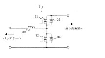
図2は、図1に示された第1電力変換器5bの詳細構成を示す回路図である。この図に示されるように、第1電力変換器5bはリアクトル30及びMOSFETなどのスイッチ31、32と、これらのスイッチにそれぞれ逆並列接続されたダイオード33、34とで構成されており、入力端子に接続されたバッテリー5aの電圧はこの回路によって昇圧されて出力端子から出力される。
FIG. 2 is a circuit diagram showing a detailed configuration of the
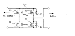
また、図3は、図1に示された第2電力変換器5cの詳細構成を示す回路図である。この図に示されるように、第2電力変換器5cは単相ブリッジ接続された例えばMOSFETなどのスイッチ20乃至23と、各スイッチに逆並列接続された寄生ダイオード24乃至27から構成されており、常時は負荷側から入力される商用電源1の交流電力を交流−直流変換して直流電力を第1変換器側に出力し、商用電源1の停電時には第1変換器側から入力される直流電力を直流−交流変換して負荷側に交流電力を出力するように電力変換動作を行うようにされている。
FIG. 3 is a circuit diagram showing a detailed configuration of the
次に、実施の形態1による無停電電源装置100の動作について図4及び図5のフローチャートを用いて説明する。
先ず、図4のフローチャートを用いて常時の動作について説明する。
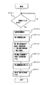
ステップS101で商用電源1に無停電電源装置100の入力端子6を接続する。これによって常閉の第1開閉器3を介して第2電力変換器5cへ交流電力が供給され、ステップS102で交流電力が第2電力変換器5cによって直流電力に変換され、制御回路5dに供給される。
Next, the operation of
First, the normal operation will be described with reference to the flowchart of FIG.
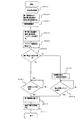
In step S101, the
この結果、ステップS103で制御回路5dが動作する。制御回路5dはステップS104で第2電力変換器5cから出力された直流電圧を制御する一方、第1電力変換器5bを動作させ、第1電力変換器5bの直流電圧を所定の電圧に降圧してバッテリー5aの充電を行う。その後、ステップS105で起動手段5eの操作を確認する。起動手段の起動スイッチを押してスイッチ入力を与えるとステップS106で制御回路5dにより第2開閉器4が閉じられ、ステップS107で負荷2へ電力が供給される。
As a result, the
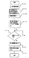
次に、図5のフローチャートを用いて商用電源1が停電した場合の動作について説明する。無停電電源装置の起動後に商用電源1が停電した場合は、制御回路5dが第1開閉器3を開いた後、第1電力変換器5bがバッテリー5aの電圧を所定の電圧に昇圧し、この電圧を第2電力変換器5cが直流−交流変換によって交流電力に変換し、第2開閉器4を経て負荷2に給電する。
Next, the operation when the
無停電電源装置100が起動する前に商用電源1が停電していた場合は、ステップS201でバッテリー5aの制御回路を含む、起動手段5eの操作を確認する。ステップS201で起動手段5eのスイッチが押されると、第1電力変換器5bを介してバッテリー5aの電力が制御回路5dへ供給され、ステップS202で制御回路5dが動作を開始する。
If the
制御回路5dの動作により、ステップS203で商用電源1との接続を遮断するため、第1開閉器3が開かれる。その後ステップS204で第1電力変換器5bによりバッテリー5aの直流電圧が所定の電圧に昇圧され、第2電力変換器5cへ供給される。
次いで、ステップS205で第2電力変換器5cによる直流―交流変換が行われる。
その後、ステップS206で制御回路5dにより、第2開閉器4が閉じられ、ステップS207で負荷2へ交流電力が供給される。
By the operation of the
Next, in step S205, DC-AC conversion is performed by the
Thereafter, the second switch 4 is closed by the
以上のように、実施の形態1による無停電電源装置100においては、バッテリー5aと第1電力変換器5bの双方に接続され制御回路5dに起動指令を発する起動手段5eを設けているため、バッテリー5aの正常時はバッテリーを電源として制御回路5dが動作するため無停電電源装置100が確実に動作し、バッテリー5aが取り外された場合またはバッテリーが劣化した場合などの異常時には商用電源1から第1開閉器3と第2電力変換器5c及び第1電力変換器5bを介して起動手段5e及び制御回路5dに電源が供給され、無停電電源装置100を起動させることができる。
As described above, in the
実施の形態2.
次に、この発明の実施の形態2を図にもとづいて説明する。図6は、実施の形態2による無停電電源装置の構成を示すブロック図、図7及び図8は、実施の形態2の動作を説明するためのフローチャートである。なお、図6において、図1と同一または相当部分には同一符号を付して説明を省略する。
Next, a second embodiment of the present invention will be described with reference to the drawings. FIG. 6 is a block diagram showing the configuration of the uninterruptible power supply according to the second embodiment, and FIGS. 7 and 8 are flowcharts for explaining the operation of the second embodiment. In FIG. 6, the same or corresponding parts as in FIG.
実施の形態2の無停電電源装置101が図1と異なる点は、バッテリー5aの異常を検出する電圧検出手段5gと、電圧検出手段5gにより例えばバッテリーの短絡等のバッテリー異常検出時に制御回路5dに起動処理をさせるため、制御回路5dに直接接続されている別の起動手段5fを設けた点である。
The uninterruptible
次に図7のフローチャートを用いて、実施の形態2による無停電電源装置の常時の動作について説明する。
先ず、ステップS301で商用電源1に無停電電源装置101の入力端子6を接続する。これにより第1開閉器3を介して第2電力変換器5cへ交流電力が供給され、ステップS302で第2電力変換器5cにより交流−直流変換が行なわれ、直流電力が生成される。
Next, the normal operation of the uninterruptible power supply according to
First, the
次に、ステップS303により第2電力変換器5cの直流出力電圧によって制御回路5dが動作する。第2電力変換器5cから出力された直流電圧を制御する制御回路5dはステップS304で第1電力変換器5bを動作させ、直流電圧を降圧してバッテリー5aの充電を行う。
Next, in step S303, the
その後、ステップS305で電圧検出手段5gにより、第1電力変換器5bの出力側バッテリー端電圧を検出し、ステップS306で検出したバッテリー端電圧が所定の電圧以上かどうかを確認する。所定の電圧以上の場合には、ステップS307で起動手段5eのスイッチ操作を確認する。起動手段のスイッチが押された場合にはステップS310で制御回路5dを経て第2開閉器4を閉じ、ステップS311で負荷2へ電力を供給する。
Thereafter, in step S305, the voltage detection means 5g detects the output side battery end voltage of the
ステップS306で検出したバッテリー5aの端電圧が所定の電圧以下の場合には、バッテリーが短絡故障している可能性があるため、ステップS308でバッテリーへの充電動作を停止し、起動手段5eが使用できないので、ステップS309で制御回路5dに直接接続されている別の起動手段5fのスイッチ入力を操作し、ステップS310で制御回路5dを経て第2開閉器4を閉じ、ステップS311で負荷2へ電力を供給する。
If the end voltage of the
制御回路5dは、上述したステップS306以降の動作後に商用電源1が停電した場合には、第1開閉器3を開くと共に、バッテリー5aの直流電圧を第1電力変換器5bにて昇圧し、第2電力変換器5cにて直流―交流変換を行い、負荷2へ電力供給を行う。
The
次に、無停電電源装置101が起動する前に商用電源1が停電していた場合におけるバッテリー5aからの起動について図8のフローチャートを用いて説明する。
ステップS401でバッテリー5aの制御回路を含む、起動手段5eの操作を確認する。ステップS401で起動手段5eのスイッチが押されると、第1電力変換器5bを介してバッテリー5aの直流電力が制御回路5dへ供給され、ステップS402で制御回路5dが動作を開始する。
Next, starting from the
In step S401, the operation of the starting means 5e including the control circuit for the
制御回路5dの動作により、ステップS403で商用電源1との接続を遮断するため、第1開閉器3が開かれる。その後、ステップS404で第1電力変換器5bによりバッテリー5aの直流電圧が所定の電圧に昇圧され、第2電力変換器5cへ供給される。
次いで、ステップS405で第2電力変換器5cによる直流―交流変換が行われる。
その後、ステップS406で制御回路5dにより、第2開閉器4が閉じられ、ステップS407で負荷2へ交流電力が供給される。
By the operation of the
Next, in step S405, DC-AC conversion is performed by the
Thereafter, the second switch 4 is closed by the
実施の形態1による無停電電源装置では、バッテリー5aが短絡故障している場合、起動手段5eはバッテリー5aに直接接続されているため、第1電力変換器5bにより起動手段5eに電源供給することができず、無停電電源装置を起動することができないという問題点があったが、実施の形態2による無停電電源装置は上述のように構成されているため、商用電源1から無停電電源装置101に電力供給されている場合には、起動手段5eのスイッチを押すことにより起動が可能であり、また、バッテリーが短絡故障している場合には電圧検出手段5gでバッテリー5aの電圧を計測して異常を検知し、充電を停止すると共に制御回路5dに直接接続された別の起動手段5fのスイッチを操作することにより起動が可能となり、負荷2へ電力供給することができる。
In the uninterruptible power supply according to the first embodiment, when the
実施の形態3.
次に、この発明の実施の形態3を図にもとづいて説明する。図9は、実施の形態3による無停電電源装置の構成を示すブロック図、図10及び図11は、実施の形態3の動作を説明するためのフローチャートである。なお、図9において、図6と同一または相当部分には同一符号を付して説明を省略する。
Next, a third embodiment of the present invention will be described with reference to the drawings. FIG. 9 is a block diagram showing the configuration of the uninterruptible power supply according to the third embodiment, and FIGS. 10 and 11 are flowcharts for explaining the operation of the third embodiment. In FIG. 9, the same or corresponding parts as in FIG.
実施の形態3の無停電電源装置102が図6と異なる点は、第1電力変換器5bと第2電力変換器5cとの間の2本の電路のそれぞれに直列に挿入され制御回路5dで開閉制御される常開の第3開閉器8a、8bと、この第3開閉器8a、8bに並列接続され、起動手段5eの操作で開閉制御される常開の第4開閉器9a、9bとを設けた点である。
The
次に、図10のフローチャートを用いて商用電源投入時の無停電電源装置102の起動動作について説明する。
先ず、ステップS501で無停電電源装置102の入力端子6を商用電源1に接続する。これにより商用電源1は第1開閉器3を介して第2電力変換器5cへ接続され、ステップS502で第2電力変換器5cにより交流−直流変換が行なわれ直流電圧が生成される。
Next, the starting operation of the
First, in step S501, the
次に、ステップS503により第2電力変換器5cの直流出力電圧によって制御回路5dが動作する。制御回路5dの動作により、ステップS504で第3開閉器8a、8bが閉路され、第1電力変換器5bに第2電力変換器5cの直流出力が与えられる。
Next, in step S503, the
これによりステップS505で第1電力変換器5bによる直流−直流変換が行なわれて降圧され、バッテリー5aが充電される。次いで、ステップS506で電圧検出手段5gにより、第1電力変換器5bの出力側バッテリー端電圧を検出し、ステップS507で検出したバッテリー端電圧が所定の電圧以上かどうかを確認する。所定の電圧以上の場合にはステップS508で起動手段5eのスイッチ操作を確認する。起動スイッチ5eが押された場合にはステップS511で制御回路5dを経て第2開閉器4を閉じ、負荷2へ電力を供給する。
Thus, in step S505, DC-DC conversion is performed by the
ステップS507で検出したバッテリー端電圧が所定の電圧未満の場合には、バッテリーが短絡故障している可能性があるため、ステップS509で充電動作を停止し、起動手段5eが使用できないので、ステップS510で制御回路5dに直接接続されている別の起動手段5fのスイッチ操作を行い、ステップS511で制御回路5dを経て第2開閉器4を閉じ、負荷2へ電力を供給する。
If the battery end voltage detected in step S507 is less than the predetermined voltage, there is a possibility that the battery is short-circuited. Therefore, the charging operation is stopped in step S509, and the starting means 5e cannot be used. In step S511, the second switch 4 is closed via the
次に、無停電電源装置102が起動する前に商用電源1が停電していた場合におけるバッテリー5aからの起動について図11のフローチャートを用いて説明する。
ステップS601でバッテリー5aの制御回路を含む、起動手段5eの操作を確認する。ステップS601で起動手段5eのスイッチが押されると、ステップS602で第4開閉器9a、9bが閉路され、第1電力変換器5bを介してバッテリー電圧が制御回路5dへ供給され、ステップS603で制御回路5dが動作を開始する。
Next, starting from the
In step S601, the operation of the starting means 5e including the control circuit for the
制御回路5dの動作により、ステップS604で商用電源1との接続を遮断するため、第1開閉器3が開路される。その後、制御回路5dにより、第3開閉器8a、8bが閉路し、ステップS605で第1電力変換器5bによりバッテリー電圧が所定の電圧に昇圧され、第2電力変換器5cへ供給される。次いで、ステップS606で第2電力変換器5cによる直流―交流変換が行われる。その後、ステップS607で制御回路5dにより第2開閉器4が閉路され、負荷2へ電力が供給される。
By the operation of the
以上のように、実施の形態3による無停電電源装置によれば、実施の形態2の効果に加えて第3開閉器8a、8b、第4開閉器9a、9bにてバッテリー側と商用電源側の絶縁が可能となり、バッテリー交換等の保守作業を安全に行うことができる。
なお、以上の説明では、第3開閉器8a、8b、第4開閉器9a、9bを第1電力変換器5bと第2電力変換器5cの間に挿入したが、起動スイッチ5eと第1電力変換器5bとの間に挿入しても良い。このような接続とすれば、バッテリーが故障した時にも端子電圧を検出し、バッテリーを第1の電力変換器から切り離して安全に起動することが可能となる。
As described above, according to the uninterruptible power supply according to the third embodiment, in addition to the effects of the second embodiment, the
In the above description, the
また、上述の第3、第4開閉器は、実施の形態1及び2に適用しても同様の効果を期待することができる。 In addition, even if the third and fourth switches described above are applied to the first and second embodiments, the same effect can be expected.
実施の形態4.
次に、この発明の実施の形態4を図にもとづいて説明する。図12は、実施の形態4による無停電電源装置の構成を示すブロック図である。この図において、図6と同一または相当部分には同一符号を付して説明を省略する。
Embodiment 4 FIG.
Next, a fourth embodiment of the present invention will be described with reference to the drawings. FIG. 12 is a block diagram showing the configuration of the uninterruptible power supply according to the fourth embodiment. In this figure, the same or corresponding parts as in FIG.
実施の形態4の無停電電源装置103が図6と異なる点は、第1開閉器3と並列に、開路時の動作が第1開閉器3より速い常開の並列開閉器10を設け、並列開閉器10を制御回路5dからの制御信号によって閉路する(一般的にa接点仕様と呼ばれる)ようにした点である。
The
無停電電源装置103の起動時には、制御回路5dの動作により、並列開閉器10を閉路し、第1開閉器3を開路する。この状態で起動手段5eが操作されると制御回路5dを経て第2開閉器4が閉路して負荷2に電力が供給される。一方、商用電源1の停電時には、商用電源1との接続をすばやく遮断するため、動作時間が第1開閉器より速い並列開閉器10を開路し、バッテリー5aの電圧を第1電力変換器5bにて昇圧し、第2電力変換器5cにて直流―交流変換を行って負荷2へ給電する。
When the
以上のように、実施の形態4による無停電電源装置によれば、開路時の動作が第1開閉器3より速い並列開閉器10を用いることにより、停電時の切替え時間を速くすることができる。
As described above, according to the uninterruptible power supply according to the fourth embodiment, the switching time at the time of power failure can be shortened by using the parallel switch 10 whose operation at the time of opening the circuit is faster than that of the
100、101、102、103 無停電電源装置、 1 商用電源、 2 負荷、
3 第1開閉器、 4 第2開閉器、 5 電力変換器、 5a バッテリー、
5b 第1電力変換器、 5c 第2電力変換器、 5d 制御回路、
5e 起動スイッチ、 5f 別の起動スイッチ、 5g 電圧検出手段、
6 入力端子、 7 出力端子、 8a、8b 第3開閉器、
9a、9b 第4開閉器、 10 並列開閉器。
100, 101, 102, 103 uninterruptible power supply, 1 commercial power supply, 2 load,
3 First switch, 4 Second switch, 5 Power converter, 5a Battery,
5b 1st power converter, 5c 2nd power converter, 5d control circuit,
5e start switch, 5f another start switch, 5g voltage detection means,
6 input terminals, 7 output terminals, 8a, 8b third switch,
9a, 9b 4th switch, 10 parallel switch.
Claims (4)
Priority Applications (1)
| Application Number | Priority Date | Filing Date | Title |
|---|---|---|---|
| JP2007033581A JP4592714B2 (en) | 2007-02-14 | 2007-02-14 | Uninterruptible power system |
Applications Claiming Priority (1)
| Application Number | Priority Date | Filing Date | Title |
|---|---|---|---|
| JP2007033581A JP4592714B2 (en) | 2007-02-14 | 2007-02-14 | Uninterruptible power system |
Publications (3)
| Publication Number | Publication Date |
|---|---|
| JP2008199819A JP2008199819A (en) | 2008-08-28 |
| JP2008199819A5 JP2008199819A5 (en) | 2009-05-28 |
| JP4592714B2 true JP4592714B2 (en) | 2010-12-08 |
Family
ID=39758262
Family Applications (1)
| Application Number | Title | Priority Date | Filing Date |
|---|---|---|---|
| JP2007033581A Active JP4592714B2 (en) | 2007-02-14 | 2007-02-14 | Uninterruptible power system |
Country Status (1)
| Country | Link |
|---|---|
| JP (1) | JP4592714B2 (en) |
Families Citing this family (2)
| Publication number | Priority date | Publication date | Assignee | Title |
|---|---|---|---|---|
| JP5810871B2 (en) * | 2011-11-30 | 2015-11-11 | オムロン株式会社 | Control apparatus and control method |
| JP5781012B2 (en) * | 2012-05-29 | 2015-09-16 | 三菱電機株式会社 | Power switching device and house |
Citations (3)
| Publication number | Priority date | Publication date | Assignee | Title |
|---|---|---|---|---|
| JP2002084682A (en) * | 2000-09-05 | 2002-03-22 | Fuji Electric Co Ltd | Uninterruptible power-supply unit and its inspection method |
| JP2006246610A (en) * | 2005-03-03 | 2006-09-14 | Meidensha Corp | Method of charging instantaneous voltage drop compensator |
| JP2007037283A (en) * | 2005-07-27 | 2007-02-08 | Omron Corp | Information processing device, uninterruptible power supply, power supply method, recording medium, and program |
-
2007
- 2007-02-14 JP JP2007033581A patent/JP4592714B2/en active Active
Patent Citations (3)
| Publication number | Priority date | Publication date | Assignee | Title |
|---|---|---|---|---|
| JP2002084682A (en) * | 2000-09-05 | 2002-03-22 | Fuji Electric Co Ltd | Uninterruptible power-supply unit and its inspection method |
| JP2006246610A (en) * | 2005-03-03 | 2006-09-14 | Meidensha Corp | Method of charging instantaneous voltage drop compensator |
| JP2007037283A (en) * | 2005-07-27 | 2007-02-08 | Omron Corp | Information processing device, uninterruptible power supply, power supply method, recording medium, and program |
Also Published As
| Publication number | Publication date |
|---|---|
| JP2008199819A (en) | 2008-08-28 |
Similar Documents
| Publication | Publication Date | Title |
|---|---|---|
| CN109562698B (en) | Vehicle system | |
| JP4102572B2 (en) | Fuel cell power generation system | |
| JP4718561B2 (en) | Actuator for elevator system | |
| JP2005143217A (en) | Separate power supply system | |
| JP5536279B1 (en) | Power storage device | |
| CN108666966B (en) | Converter with short-circuit fault detection function and short-circuit fault detection method thereof | |
| WO2018163494A1 (en) | Vehicle power supply device | |
| JP6133827B2 (en) | Motor driving device having welding detection function of magnetic contactor | |
| JP4763660B2 (en) | Power system | |
| EP3670238B1 (en) | Power supply system and operation method thereof | |
| CN105379045A (en) | LPS architecture for UPS systems | |
| JP5941826B2 (en) | Bidirectional power supply device for secondary battery and control method thereof | |
| JP5347362B2 (en) | Emergency power circuit | |
| JP4251287B2 (en) | Power supply method for self-supporting load in fuel cell power generator | |
| JP4592714B2 (en) | Uninterruptible power system | |
| JP2014220152A (en) | Power generation device | |
| JP2017011910A (en) | Uninterruptible power supply device | |
| JP2008283729A (en) | Uninterruptible power supply unit | |
| JP6203012B2 (en) | Grid-connected inverter device | |
| JP5747771B2 (en) | Inverter | |
| JP2009254102A (en) | Uninterruptible power supply device | |
| JP4837272B2 (en) | Elevator control device | |
| JP6089820B2 (en) | Grid connection system for fuel cells | |
| JP2013078183A (en) | Power generation system | |
| JP4932604B2 (en) | Voltage compensator |
Legal Events
| Date | Code | Title | Description |
|---|---|---|---|
| A521 | Request for written amendment filed |
Free format text: JAPANESE INTERMEDIATE CODE: A523 Effective date: 20090408 |
|
| A621 | Written request for application examination |
Free format text: JAPANESE INTERMEDIATE CODE: A621 Effective date: 20090408 |
|
| A977 | Report on retrieval |
Free format text: JAPANESE INTERMEDIATE CODE: A971007 Effective date: 20100118 |
|
| A131 | Notification of reasons for refusal |
Free format text: JAPANESE INTERMEDIATE CODE: A131 Effective date: 20100223 |
|
| A521 | Request for written amendment filed |
Free format text: JAPANESE INTERMEDIATE CODE: A523 Effective date: 20100331 |
|
| TRDD | Decision of grant or rejection written | ||
| A01 | Written decision to grant a patent or to grant a registration (utility model) |
Free format text: JAPANESE INTERMEDIATE CODE: A01 Effective date: 20100907 |
|
| A01 | Written decision to grant a patent or to grant a registration (utility model) |
Free format text: JAPANESE INTERMEDIATE CODE: A01 |
|
| A61 | First payment of annual fees (during grant procedure) |
Free format text: JAPANESE INTERMEDIATE CODE: A61 Effective date: 20100914 |
|
| FPAY | Renewal fee payment (event date is renewal date of database) |
Free format text: PAYMENT UNTIL: 20130924 Year of fee payment: 3 |
|
| R151 | Written notification of patent or utility model registration |
Ref document number: 4592714 Country of ref document: JP Free format text: JAPANESE INTERMEDIATE CODE: R151 |
|
| FPAY | Renewal fee payment (event date is renewal date of database) |
Free format text: PAYMENT UNTIL: 20130924 Year of fee payment: 3 |
|
| R250 | Receipt of annual fees |
Free format text: JAPANESE INTERMEDIATE CODE: R250 |
|
| R250 | Receipt of annual fees |
Free format text: JAPANESE INTERMEDIATE CODE: R250 |
|
| R250 | Receipt of annual fees |
Free format text: JAPANESE INTERMEDIATE CODE: R250 |
|
| R250 | Receipt of annual fees |
Free format text: JAPANESE INTERMEDIATE CODE: R250 |
|
| R250 | Receipt of annual fees |
Free format text: JAPANESE INTERMEDIATE CODE: R250 |
|
| R250 | Receipt of annual fees |
Free format text: JAPANESE INTERMEDIATE CODE: R250 |
|
| R250 | Receipt of annual fees |
Free format text: JAPANESE INTERMEDIATE CODE: R250 |
|
| R250 | Receipt of annual fees |
Free format text: JAPANESE INTERMEDIATE CODE: R250 |
|
| R250 | Receipt of annual fees |
Free format text: JAPANESE INTERMEDIATE CODE: R250 |