JP2017011910A - Uninterruptible power supply device - Google Patents
Uninterruptible power supply device Download PDFInfo
- Publication number
- JP2017011910A JP2017011910A JP2015126130A JP2015126130A JP2017011910A JP 2017011910 A JP2017011910 A JP 2017011910A JP 2015126130 A JP2015126130 A JP 2015126130A JP 2015126130 A JP2015126130 A JP 2015126130A JP 2017011910 A JP2017011910 A JP 2017011910A
- Authority
- JP
- Japan
- Prior art keywords
- converter
- power supply
- storage battery
- abnormality
- power
- Prior art date
- Legal status (The legal status is an assumption and is not a legal conclusion. Google has not performed a legal analysis and makes no representation as to the accuracy of the status listed.)
- Pending
Links
Images


Abstract
Description
本発明は、無停電電源装置のDC−DCコンバータ装置の軽負荷での運転継続性能向上に関するものである。 The present invention relates to improvement of operation continuation performance at a light load of a DC-DC converter device of an uninterruptible power supply.
無停電電源装置の目的は商用電源が異常状態の場合に、蓄電池の電力により無停電電源装置から電力を供給し続けることである。商用電源が異常状態の場合は、蓄電池の電力をAC−DCコンバータに供給する切換え手段が動作し、AC−DCコンバータがDC−DCコンバータとして動作し、蓄電池の電力により負荷へ電力を供給する技術が知られている。特許文献1には、「通常蓄電池を充電するDC−DCコンバータは、商用電源異常時に蓄電池を昇圧して放電しインバータへ直流電力を供給する。商用電源正常時に交流を直流に変換するコンバータを、商用電源に異常が発生した場合にコンバータ動作を停止し、切換器はコンバータと蓄電池を接続した状態にする。この状態で、コンバータのスイッチング素子がDC−DCコンバータと同様の動作をすることにより、蓄電池よりインバータへの電力供給を可能とする。この手段により、商用電源異常時に動作するDC−DCコンバータが複数構成になり、DC−DCコンバータに流れる電流は低減し、使用するスイッチング素子の低価格化や員数低減が可能であり、DC−DCコンバータ用リアクトルの小型化が可能となる」ことが記載されている。 The purpose of the uninterruptible power supply is to continue supplying power from the uninterruptible power supply by the power of the storage battery when the commercial power supply is in an abnormal state. When the commercial power supply is in an abnormal state, switching means for supplying the power of the storage battery to the AC-DC converter operates, the AC-DC converter operates as a DC-DC converter, and the power is supplied to the load by the power of the storage battery It has been known. Patent Document 1 states that “a DC-DC converter that charges a normal storage battery boosts and discharges the storage battery when the commercial power supply is abnormal and supplies DC power to the inverter. A converter that converts AC to DC when the commercial power supply is normal, When an abnormality occurs in the commercial power supply, the converter operation is stopped, and the switching device is connected to the converter and the storage battery.In this state, the switching element of the converter performs the same operation as the DC-DC converter, This means that power can be supplied from the storage battery to the inverter.This means that there are multiple DC-DC converters that operate when the commercial power supply is abnormal, so that the current flowing through the DC-DC converter is reduced and the switching elements used are inexpensive. It is possible to reduce the number of units and reduce the number of units, and the size of the reactor for the DC-DC converter can be reduced. " To have.
特許文献1では、充放電用のDC−DCコンバータあるいは、DC−DCコンバータとして動作させるAC−DCコンバータのいずれかが故障した場合には、無停電電源装置は最大の負荷電力を供給することができなくなるため、装置が停止してしまうことが考えられる。 In Patent Document 1, when either a DC-DC converter for charging / discharging or an AC-DC converter operated as a DC-DC converter fails, the uninterruptible power supply can supply the maximum load power. Since it becomes impossible, it can be considered that the apparatus stops.
そこで本発明では、商用電源の異常が発生し、AC−DCコンバータの前段の前記切換え手段で商用電源側から蓄電池側に切換えた後に、充放電用DC−DCコンバータまたはAC−DCコンバータが故障した場合において、無停電電源装置から安定した電力を供給し続けることができる技術を提供することを目的とする。 Therefore, in the present invention, an abnormality of the commercial power supply occurs, and the charge / discharge DC-DC converter or the AC-DC converter breaks down after switching from the commercial power supply side to the storage battery side by the switching means in the preceding stage of the AC-DC converter. In some cases, an object is to provide a technique capable of continuing to supply stable power from an uninterruptible power supply.
上記課題を解決するために、例えば、商用電源を直流に変換するAC−DCコンバータと、AC−DCコンバータで変換された直流電圧を平滑するコンデンサと、平滑コンデンサで平滑された直流電圧を交流電圧に変換して負荷に電力を供給するインバータと、商用電源とAC−DCコンバータを連結する連結スイッチと、商用電源から電力が正常に供給されるときは、AC−DCコンバータで変換された直流電圧をインバータに供給するとともに直流電圧を降圧して蓄電池を充電し、商用電源からの電力が異常状態のときは、充電された蓄電池の電力を昇圧して放電することによりインバータに直流電力を供給するDC−DCコンバータと、AC−DCコンバータと蓄電池との間に設けられ、商用電源側から蓄電池側に切り替えることにより蓄電池の電力をAC−DCコンバータに供給することができる切換え部と、商用電源が異常状態のときは、AC−DCコンバータまたはDC−DCコンバータの異常の有無を検出するとともに、AC−DCコンバータまたはDC−DCコンバータのいずれか一方に異常が検出された場合には、インバータに接続された負荷の大きさに基づいて、2つのコンバータのうち正常なコンバータのみで蓄電池からの電力供給を行うか、AC−DCコンバータおよびDC−DCコンバータからの電力供給を停止するかを決める制御部と、を有することを特徴とする無停電電源装置である。 In order to solve the above problems, for example, an AC-DC converter that converts commercial power to DC, a capacitor that smoothes the DC voltage converted by the AC-DC converter, and a DC voltage that is smoothed by the smoothing capacitor are converted to AC voltage. An inverter that converts power into a load and supplies power to the load, a connection switch that connects the commercial power source and the AC-DC converter, and a DC voltage converted by the AC-DC converter when power is normally supplied from the commercial power source Is supplied to the inverter and the storage battery is charged by reducing the DC voltage. When the power from the commercial power supply is abnormal, the inverter is supplied with DC power by boosting and discharging the charged storage battery. It is provided between the DC-DC converter, the AC-DC converter and the storage battery, and is switched from the commercial power supply side to the storage battery side. When the switching unit that can supply the power of the storage battery to the AC-DC converter and the commercial power supply is in an abnormal state, the AC-DC converter or the DC-DC converter detects whether there is an abnormality and the AC-DC converter or If an abnormality is detected in one of the DC-DC converters, based on the size of the load connected to the inverter, whether power is supplied from the storage battery with only a normal converter of the two converters, An uninterruptible power supply comprising: an AC-DC converter and a control unit that determines whether to stop power supply from the DC-DC converter.
本発明によれば、商用電源の異常が発生し、AC−DCコンバータの前段の前記切換え手段で商用電源側から蓄電池側に切換えた後に、充放用DC−DCコンバータまたはAC−DCコンバータが故障した場合において、無停電電源装置から安定した電力を供給し続けることができる技術を提供することができる。 According to the present invention, an abnormality of the commercial power supply occurs, and after switching from the commercial power supply side to the storage battery side by the switching means in the preceding stage of the AC-DC converter, the charge / discharge DC-DC converter or the AC-DC converter fails. In this case, it is possible to provide a technology that can continue to supply stable power from the uninterruptible power supply.
以下、実施例を図面を用いて説明する。 Hereinafter, examples will be described with reference to the drawings.
図1は、本発明の対象となる無停電電源装置の構成図である。 FIG. 1 is a configuration diagram of an uninterruptible power supply apparatus that is an object of the present invention.
商用電源1からの交流の一端は、連結スイッチ3とリアクトル13、14、15を介して、AC−DCコンバータ38に接続される。AC−DCコンバータ38は、それぞれ直列接続されたスイッチング素子19、20、21、22、23、24から構成され、商用電源1は、各スイッチング素子の接続中点に接続される。これらのスイッチング素子19、20、21、22、23、24は、制御回路37からの信号によって駆動される。
One end of the alternating current from the commercial power source 1 is connected to the AC-
連結スイッチ3とリアクトル13、14、15の接続中点には、フィルタコンデンサ10、11、12が接続され、一端はコンデンサ同士で接続される。
AC−DCコンバータ38の他端には、直流コンデンサ33が接続される。
A
さらに直流コンデンサ33の両端は、インバータ40に接続される。インバータ40は、それぞれ直列接続されたスイッチング素子27、28、29、30、31、32で構成される。これらのスイッチング素子27、28、29、30、31、32も、制御回路37からの信号によって駆動される。
Further, both ends of the
これらのスイッチング素子27、28、29、30、31、32のそれぞれの接続中点はフィルタ34を介して負荷35に接続される。
The connection midpoint of each of these
また、直流コンデンサ33の両端は、DC−DCコンバータを構成する直列接続されたスイッチング素子25、26の両端にも接続される。このスイッチング素子25、26も制御回路37からの信号によって駆動される。
Further, both ends of the direct
このスイッチング素子25、26の接続中点は、直列接続された直流リアクトル18を介して蓄電池36に接続される。蓄電池36の一端はスイッチング素子26の一端に接続される。
The connection midpoint of the
切換えスイッチ16の一端は、連結スイッチ3とリアクトル13の接続中点に接続され、切換えスイッチ16のもう一端は直流スイッチ17と直流リアクトル18の接続中点に接続される。
One end of the
なお、連結スイッチ3、切換えスイッチ16、直流スイッチ17も制御回路37からの信号によって駆動される。
Note that the
AC−DCコンバータ38は、商用電源1の交流を直流に変換する。直流はさらにインバータ40で交流に逆変換され、フィルタ34を介して負荷35に電力を供給する。
The AC-
また、コンデンサ33は、AC−DCコンバータ38によって変換された直流電圧を平滑するために装備する。このコンデンサ33の直流電圧は蓄電池36の電圧よりも大きいものとする。
Further, the
また、充放電用のDC−DCコンバータ39は、商用電源1が正常のとき降圧チョッパ回路として動作をし、直流リアクトル18を介して蓄電池36を充電する。一方、商用電源1が異常のときは、AC−DCコンバータ38は停止し、充放電用のDC−DCコンバータ39が昇圧チョッパ回路として動作し、直流リアクトル18を介して蓄電池36からインバータ40に直流電力を供給する。さらに連結スイッチ3を開放し、一旦停止したAC−DCコンバータ38はリアクトル13を介して、フィルタコンデンサ10を蓄電池電圧36となるように電荷の充電および放電を実施した後、切換えスイッチ16を閉じる。AC−DCコンバータ38を構成する直列に接続した半導体スイッチ19、20は昇圧チョッパ回路として動作し、リアクトル13を介して、蓄電池36からインバータ40に直流電力を供給する。このように、AC−DCコンバータ38およびDC−DCコンバータ39を並列状態で放電運転を行うことにより、コンバータに流れる電流は低減し、使用するスイッチング素子の低価格化や員数低減が可能であり、コンバータの小型化が可能となる。
Further, the charging / discharging DC-
AC−DCコンバータ38およびDC−DCコンバータ39は、異常を検出する検出器41および検出器42をそれぞれ設けている。これらの検出器によりコンバータ38または放電用のDC−DCコンバータ39のいずれかの故障を検出した場合であって、制御回路37にて負荷35が所定値より小さいと判断した場合には、AC−DCコンバータフューズ44またはDC−DCコンバータフューズ45により故障した回路が切り離され、正常な回路だけで蓄電池36からインバータ40に直流電力を供給する。また、制御回路37にて負荷が所定値より大きいと判断した場合は、安定した電源を供給することができなくなるため、いずれのコンバータの動作も停止させて給電を停止する。なお、この負荷35の所定値は、AC−DCコンバータ38の耐量によって決められる値である。このように、本実施例では、商用電源の異常が発生し、AC−DCコンバータ38の切り替えスイッチにより商用電源側から蓄電池側に切換えた後に、DC−DCコンバータ39またはAC−DCコンバータ38が故障した場合において、装置の負荷条件により動作を切換える動作を行う。具体的には装置負荷が小さい場合には、AC−DCコンバータ38またはDC−DCコンバータ39のうち、故障していないコンバータで電力を供給することにより、無停電電源装置から電力を供給し続けることができる。つまり、故障したDC−DCコンバータの分の電力をもう一方の故障していないDC−DCコンバータが供給することにより、無停電電源装置から電力を供給し、運転を継続することができる。
The AC-
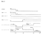
図2は、商用電源異常時で、かつ負荷35が軽い場合であって、DC−DCコンバータ39が異常となった場合の商用電源1、連結スイッチ3、直流スイッチ17、切換えスイッチ16、AC−DCコンバータ38、DC−DCコンバータ39のタイムチャートを示す。
FIG. 2 shows a case where the commercial power source is abnormal and the
図2の上から順に、商用電源1、連結スイッチ3、直流スイッチ17、切換えスイッチ16、AC−DCコンバータ38、DC−DCコンバータ39の各時刻における動作を示している。
The operation at each time of the commercial power source 1, the
まず、時刻t1までは商用電源1が正常状態であるため、連結スイッチ3はON、直流スイッチ17はON、切り替えスイッチ16はOFF、AC−DCコンバータ38はAC−DC運転を行い、DC−DCコンバータ39は降圧チョッパ回路運転を行う。
First, since the commercial power source 1 is in a normal state until time t1, the
次に、時刻t1になり、商用電源1が異常状態になった場合、連結スイッチ3をOFFにするとともにAC−DCコンバータ38を停止させ、DC−DCコンバータ39を昇圧チョッパ回路運転させて蓄電池36からインバータ40に直流電力を供給する。
Next, at time t1, when the commercial power source 1 is in an abnormal state, the
次に、時刻t2において切換えスイッチ16を閉じたのちに、フィルタコンデンサ10が蓄電池電圧36になるようにAC−DCコンバータ38を駆動させる。ここで、AC−DCコンバータ38が昇圧運転を行うため、時刻t2〜t3においてはDC−DCコンバータ39はその分の電力量を減らした運転を行う。
Next, after closing the
時刻t3においてDC−DCコンバータ39に故障が発生したとする。このとき負荷26が所定値よりも大きい場合はDC−DCコンバータ39を回路から切り離し、AC−DCコンバータ38の昇圧運転を行う。このとき、AC−DCコンバータ38は、時刻t2〜t3に稼働していたDC−DCコンバータ39の電力量を担保するように駆動するため、時刻t3において出力電力量が増えている。なお、t3以降のDC−DCコンバータ39は故障による停止状態にある。
Assume that a failure occurs in the DC-
図3は、商用電源異常になってからDC−DCコンバータ39が故障してAC−DCコンバータ38のみで負荷へ電力を供給するまでの動作フローチャートを示す。
FIG. 3 shows an operation flowchart from when the commercial power supply becomes abnormal until the DC-
商用電源1で異常が発生した場合(S301)、AC−DCコンバータ38の運転を停止する(S302)。次に、連結スイッチ3をOFFにした後(S303)、DC−DCコンバータ39の昇圧回路運転を動作させる(S304)。次に切換えスイッチ16をONにし(S305)AC−DCコンバータ38の昇圧回路運転を行う(S306)。このとき、AC−DCコンバータ38の電力量分を削減した電力量を出力するようにDC−DCコンバータ39を稼働させる(S307)。次にDC−DCコンバータ39の昇圧の異常があるか否かを判定する(S308)。異常がある場合は(S308のYES)負荷26の負荷状態を判定する(S309)。負荷状態が所定値未満の場合は(S309のYES)、DC−DCコンバータ39を回路から切り離し(S310)、AC−DCコンバータ38の昇圧回路運転を行う(S312)。一方、負荷状態が所定値以上の場合は(S309のNO)、AC−DCコンバータ38の運転を停止する。
When an abnormality occurs in the commercial power source 1 (S301), the operation of the AC-
なお、AC−DCコンバータ38が異常状態になった場合も図3のフローと同様の動作を行う。すなわち、AC−DCコンバータ38の異常の有無を判定し、負荷状態に応じてAC−DCコンバータ38を回路から切り離してDC−DCコンバータ39の昇圧回路運転を行うか、DC−DCコンバータ39の運転を停止する。
Even when the AC-
このように、商用電源の異常時にAC−DCコンバータ38またはDC−DCコンバータ39が故障した場合において、負荷条件によってAC−DCコンバータ38およびDC−DCコンバータ39の動作切換えを行うことで、重負荷の場合は装置を停止して安定した電力を供給することができなくなることを防ぎ、軽負荷の場合は故障したコンバータを切り離し故障状態でないコンバータを稼働させることで運転継続性能を向上することができる。
As described above, when the AC-
1…商用電源
3…連結スイッチ
10〜12…フィルタコンデンサ
13〜15…リアクトル
16…切換えスイッチ
17…直流スイッチ
18…直流リアクトル
19〜32…スイッチング素子
33…直流コンデンサ
34…フィルタ
35…負荷
36…蓄電池
37…制御回路
38…AC−DCコンバータ
39…DC−DCコンバータ
40…インバータ
41…AC−DCコンバータ故障検出器
42…DC−DCコンバータ故障検出器
43…インバータ故障検出器
44…AC−DCコンバータフューズ
45…DC−DCコンバータフューズ
46…インバータフューズ
DESCRIPTION OF SYMBOLS 1 ...
Claims (4)
前記AC−DCコンバータで変換された直流電圧を平滑するコンデンサと、
前記平滑コンデンサで平滑された直流電圧を交流電圧に変換して負荷に電力を供給するインバータと、
前記商用電源と前記AC−DCコンバータを連結する連結スイッチと、
前記商用電源から電力が正常に供給されるときは、前記AC−DCコンバータで変換された直流電圧を前記インバータに供給するとともに前記直流電圧を降圧して蓄電池を充電し、前記商用電源からの電力が異常状態のときは、前記充電された蓄電池の電力を昇圧して放電することにより前記インバータに直流電力を供給するDC−DCコンバータと、
前記AC−DCコンバータと前記蓄電池との間に設けられ、前記商用電源側から前記蓄電池側に切り替えることにより前記蓄電池の電力を前記AC−DCコンバータに供給することができる切換え部と、
前記商用電源が異常状態のときは、前記AC−DCコンバータまたは前記DC−DCコンバータの異常の有無を検出するとともに、前記AC−DCコンバータまたは前記DC−DCコンバータのいずれか一方に異常が検出された場合には、前記インバータに接続された負荷の大きさに基づいて、前記2つのコンバータのうち正常なコンバータのみで前記蓄電池からの電力供給を行うか、前記AC−DCコンバータおよび前記DC−DCコンバータからの電力供給を停止するかを決める制御部と、
を有する無停電電源装置。 An AC-DC converter that converts commercial power into direct current;
A capacitor for smoothing the DC voltage converted by the AC-DC converter;
An inverter that converts the DC voltage smoothed by the smoothing capacitor into an AC voltage and supplies power to the load;
A connection switch for connecting the commercial power supply and the AC-DC converter;
When electric power is normally supplied from the commercial power source, the DC voltage converted by the AC-DC converter is supplied to the inverter and the DC voltage is stepped down to charge the storage battery. Is an abnormal state, a DC-DC converter that supplies DC power to the inverter by boosting and discharging the power of the charged storage battery;
A switching unit that is provided between the AC-DC converter and the storage battery, and that can supply power of the storage battery to the AC-DC converter by switching from the commercial power supply side to the storage battery side;
When the commercial power supply is in an abnormal state, the presence of an abnormality in the AC-DC converter or the DC-DC converter is detected, and an abnormality is detected in either the AC-DC converter or the DC-DC converter. In this case, based on the magnitude of the load connected to the inverter, power is supplied from the storage battery by only a normal converter of the two converters, or the AC-DC converter and the DC-DC A control unit for determining whether to stop the power supply from the converter;
Uninterruptible power supply.
前記負荷の大きさが所定値以下の場合は、前記2つのコンバータのうち正常なコンバータを構成するスイッチング素子によって前記蓄電池の電力を昇圧させるとともに、異常が検出されたコンバータを回路から切り離す無停電電源装置。 In the uninterruptible power supply according to claim 1,
An uninterruptible power supply that boosts the power of the storage battery by a switching element that constitutes a normal converter of the two converters and disconnects the converter in which an abnormality has been detected from the circuit when the magnitude of the load is a predetermined value or less apparatus.
前記異常が検出されたコンバータが前記異常が検出される前に出力していた電力を出力するように、前記正常なコンバータを構成するスイッチング素子によって前記蓄電池の電力を昇圧させる無停電電源装置。 In the uninterruptible power supply according to claim 2,
An uninterruptible power supply that boosts the power of the storage battery by a switching element that constitutes the normal converter so that the converter in which the abnormality is detected outputs the power that was output before the abnormality was detected.
前記切換え部を前記商用電源側から前記蓄電池側に切り替え、前記2つのコンバータのうち正常なコンバータを構成するスイッチング素子によって前記AC−DCコンバータを前記DC−DCコンバータとして動作させる無停電電源装置。 In the uninterruptible power supply according to claim 2,
An uninterruptible power supply apparatus that switches the switching unit from the commercial power supply side to the storage battery side and operates the AC-DC converter as the DC-DC converter by a switching element that constitutes a normal converter of the two converters.
Priority Applications (1)
| Application Number | Priority Date | Filing Date | Title |
|---|---|---|---|
| JP2015126130A JP2017011910A (en) | 2015-06-24 | 2015-06-24 | Uninterruptible power supply device |
Applications Claiming Priority (1)
| Application Number | Priority Date | Filing Date | Title |
|---|---|---|---|
| JP2015126130A JP2017011910A (en) | 2015-06-24 | 2015-06-24 | Uninterruptible power supply device |
Publications (1)
| Publication Number | Publication Date |
|---|---|
| JP2017011910A true JP2017011910A (en) | 2017-01-12 |
Family
ID=57764218
Family Applications (1)
| Application Number | Title | Priority Date | Filing Date |
|---|---|---|---|
| JP2015126130A Pending JP2017011910A (en) | 2015-06-24 | 2015-06-24 | Uninterruptible power supply device |
Country Status (1)
| Country | Link |
|---|---|
| JP (1) | JP2017011910A (en) |
Cited By (4)
| Publication number | Priority date | Publication date | Assignee | Title |
|---|---|---|---|---|
| CN109398093A (en) * | 2018-12-07 | 2019-03-01 | 安徽华菱汽车有限公司 | A kind of control method of electronic radiator fan, system, device and pure electric vehicle |
| WO2019049301A1 (en) * | 2017-09-08 | 2019-03-14 | 東芝三菱電機産業システム株式会社 | Converter and uninterruptible power supply device using same |
| EP3790156A1 (en) * | 2019-09-03 | 2021-03-10 | Santak Electronic (Shenzhen) Co., Ltd. | A multi-input power converter, a controlling method thereof and an uninterrupted power supply including the same |
| CN113300579A (en) * | 2020-02-24 | 2021-08-24 | 株洲中车时代电气股份有限公司 | Multisource power supply equipment and system of engineering vehicle |
Citations (7)
| Publication number | Priority date | Publication date | Assignee | Title |
|---|---|---|---|---|
| JPS59185171A (en) * | 1983-04-05 | 1984-10-20 | Nippon Electric Ind Co Ltd | Protecting circuit of inverter device in parallel redundancy operation system |
| JPS62160037A (en) * | 1986-01-07 | 1987-07-16 | 富士通株式会社 | Source control system |
| JPH04244745A (en) * | 1991-01-28 | 1992-09-01 | Mitsubishi Electric Corp | Controller for ac elevator |
| JPH07115773A (en) * | 1993-10-14 | 1995-05-02 | Toshiba Corp | Uninterruptibe power source |
| JPH1118295A (en) * | 1997-06-27 | 1999-01-22 | Kofu Nippon Denki Kk | Parallel operation power supply control method |
| JP2009131122A (en) * | 2007-11-27 | 2009-06-11 | Hitachi Ltd | Uninterruptible power supply device |
| JP2013027289A (en) * | 2011-07-26 | 2013-02-04 | Yokogawa Electric Corp | Power supply device and redundant power supply device using the same |
-
2015
- 2015-06-24 JP JP2015126130A patent/JP2017011910A/en active Pending
Patent Citations (7)
| Publication number | Priority date | Publication date | Assignee | Title |
|---|---|---|---|---|
| JPS59185171A (en) * | 1983-04-05 | 1984-10-20 | Nippon Electric Ind Co Ltd | Protecting circuit of inverter device in parallel redundancy operation system |
| JPS62160037A (en) * | 1986-01-07 | 1987-07-16 | 富士通株式会社 | Source control system |
| JPH04244745A (en) * | 1991-01-28 | 1992-09-01 | Mitsubishi Electric Corp | Controller for ac elevator |
| JPH07115773A (en) * | 1993-10-14 | 1995-05-02 | Toshiba Corp | Uninterruptibe power source |
| JPH1118295A (en) * | 1997-06-27 | 1999-01-22 | Kofu Nippon Denki Kk | Parallel operation power supply control method |
| JP2009131122A (en) * | 2007-11-27 | 2009-06-11 | Hitachi Ltd | Uninterruptible power supply device |
| JP2013027289A (en) * | 2011-07-26 | 2013-02-04 | Yokogawa Electric Corp | Power supply device and redundant power supply device using the same |
Cited By (5)
| Publication number | Priority date | Publication date | Assignee | Title |
|---|---|---|---|---|
| WO2019049301A1 (en) * | 2017-09-08 | 2019-03-14 | 東芝三菱電機産業システム株式会社 | Converter and uninterruptible power supply device using same |
| CN109398093A (en) * | 2018-12-07 | 2019-03-01 | 安徽华菱汽车有限公司 | A kind of control method of electronic radiator fan, system, device and pure electric vehicle |
| CN109398093B (en) * | 2018-12-07 | 2023-08-15 | 安徽华菱汽车有限公司 | Control method, system and device of electronic cooling fan and pure electric vehicle |
| EP3790156A1 (en) * | 2019-09-03 | 2021-03-10 | Santak Electronic (Shenzhen) Co., Ltd. | A multi-input power converter, a controlling method thereof and an uninterrupted power supply including the same |
| CN113300579A (en) * | 2020-02-24 | 2021-08-24 | 株洲中车时代电气股份有限公司 | Multisource power supply equipment and system of engineering vehicle |
Similar Documents
| Publication | Publication Date | Title |
|---|---|---|
| US9154000B2 (en) | Uninterruptible power supply apparatus including a control circuit that executes a first mode when supply of a first AC electric power from a commercial AC power supply is resumed at a time of discharge end | |
| CN103227496B (en) | Apparatus for discharging DC-link capacitor for electric vehicle charger | |
| US10811898B2 (en) | Uninterruptible power supply device | |
| KR101223260B1 (en) | Battery charge system and method for parallel uninterruptible power supply devices | |
| WO2018087876A1 (en) | Uninterruptible power source apparatus | |
| TWI527356B (en) | Power supply device and its operation method | |
| US9859809B2 (en) | Power conversion device | |
| JP2017011910A (en) | Uninterruptible power supply device | |
| US20170331311A1 (en) | Electric energy storage apparatus | |
| JP6410299B2 (en) | Uninterruptible power system | |
| JP2012075274A (en) | Uninterruptible power supply | |
| JP2017085780A (en) | Dc power feeding system | |
| JP2008236993A (en) | Semiconductor power conversion system | |
| JP2004048938A (en) | Voltage compensation apparatus | |
| JP6468593B2 (en) | Power storage system | |
| JP6092800B2 (en) | Uninterruptible power supply system | |
| JP5819783B2 (en) | Uninterruptible power supply system | |
| KR100661470B1 (en) | Un-interrupted Switching Mode Power Supply | |
| CN109075605B (en) | Uninterruptible power supply device | |
| US10886843B2 (en) | Electric power supplying system | |
| JP2001178024A (en) | Emergency power supply unit | |
| US9960636B2 (en) | Power supply system and direct-current converter thereof | |
| KR102566563B1 (en) | power supply system | |
| JP6095894B2 (en) | Voltage drop protection device for DC power supply | |
| CN110739765A (en) | DC power supply system |
Legal Events
| Date | Code | Title | Description |
|---|---|---|---|
| RD04 | Notification of resignation of power of attorney |
Free format text: JAPANESE INTERMEDIATE CODE: A7424 Effective date: 20170111 |
|
| RD04 | Notification of resignation of power of attorney |
Free format text: JAPANESE INTERMEDIATE CODE: A7424 Effective date: 20170113 |
|
| A621 | Written request for application examination |
Free format text: JAPANESE INTERMEDIATE CODE: A621 Effective date: 20180518 |
|
| A977 | Report on retrieval |
Free format text: JAPANESE INTERMEDIATE CODE: A971007 Effective date: 20190219 |
|
| A131 | Notification of reasons for refusal |
Free format text: JAPANESE INTERMEDIATE CODE: A131 Effective date: 20190226 |
|
| A02 | Decision of refusal |
Free format text: JAPANESE INTERMEDIATE CODE: A02 Effective date: 20190917 |