JP4592297B2 - Sealed battery - Google Patents
Sealed battery Download PDFInfo
- Publication number
- JP4592297B2 JP4592297B2 JP2004032326A JP2004032326A JP4592297B2 JP 4592297 B2 JP4592297 B2 JP 4592297B2 JP 2004032326 A JP2004032326 A JP 2004032326A JP 2004032326 A JP2004032326 A JP 2004032326A JP 4592297 B2 JP4592297 B2 JP 4592297B2
- Authority
- JP
- Japan
- Prior art keywords
- power generation
- battery
- generation element
- sealed
- resin film
- Prior art date
- Legal status (The legal status is an assumption and is not a legal conclusion. Google has not performed a legal analysis and makes no representation as to the accuracy of the status listed.)
- Expired - Fee Related
Links
Images


Classifications
-
- Y—GENERAL TAGGING OF NEW TECHNOLOGICAL DEVELOPMENTS; GENERAL TAGGING OF CROSS-SECTIONAL TECHNOLOGIES SPANNING OVER SEVERAL SECTIONS OF THE IPC; TECHNICAL SUBJECTS COVERED BY FORMER USPC CROSS-REFERENCE ART COLLECTIONS [XRACs] AND DIGESTS
- Y02—TECHNOLOGIES OR APPLICATIONS FOR MITIGATION OR ADAPTATION AGAINST CLIMATE CHANGE
- Y02E—REDUCTION OF GREENHOUSE GAS [GHG] EMISSIONS, RELATED TO ENERGY GENERATION, TRANSMISSION OR DISTRIBUTION
- Y02E60/00—Enabling technologies; Technologies with a potential or indirect contribution to GHG emissions mitigation
- Y02E60/10—Energy storage using batteries
Description
本発明は金属ラミネート樹脂フィルムから成る外装材で発電要素を被包封止した構造を有する密閉型電池に係り、特に発電要素から導出される外部端子の封止構造を改良し、外装材の封止部を経由する漏液を防止して電池の信頼性を向上させ、かつ封止部の面積を低減して電池内に占める発電要素の割合を増加せしめて電池の体積エネルギー密度(電池容量)を増加させた密閉型電池に関する。 The present invention relates to a sealed battery having a structure in which a power generation element is encapsulated with an exterior material made of a metal laminate resin film. In particular, the sealing structure of an external terminal derived from the power generation element is improved, and the exterior material is sealed. The battery volume energy density (battery capacity) is improved by preventing leakage through the stop and improving battery reliability and reducing the sealing area to increase the proportion of power generation elements in the battery. The present invention relates to a sealed battery having an increased number.
近年、ビデオカメラやヘッドホンステレオなどの携帯電子機器における急速な高性能化,軽量化および小型化を指向した技術展開には目覚しいものがあり、これらの電子機器を長時間稼動させるための駆動電源となる二次電池の高エネルギー化および高容量化への技術的要求も一段と高まっている。 In recent years, there have been remarkable developments in technologies aimed at rapid performance enhancement, weight reduction, and miniaturization in portable electronic devices such as video cameras and headphone stereos, and a drive power source for operating these electronic devices for a long time. Technical requirements for higher energy and higher capacity of the secondary battery are also increasing.
これらの技術的要求に対応するため、リチウム金属、リチウム合金、もしくは炭素質材料のようなリチウムを吸蔵、放出できる物質を負極材料に使用した非水電解液二次電池の開発が活発に進められるようになった。この非水電解液二次電池のなかでも、電池の発電要素以外が占める体積を減少させることが、電池の高エネルギー化および小型化に有利であるという技術的観点から、従来から電池外装材として使用されていた鉄やアルミニウム製の金属缶の代わりに、より薄肉化が可能な金属ラミネート樹脂フィルムを外装材に使用した密閉型電池が注目されている。 In order to meet these technical demands, the development of non-aqueous electrolyte secondary batteries using materials that can occlude and release lithium, such as lithium metal, lithium alloys, or carbonaceous materials, is actively promoted. It became so. Among these non-aqueous electrolyte secondary batteries, from the technical point of view that reducing the volume occupied by elements other than the power generation element of the battery is advantageous for increasing the energy and size of the battery, it has been conventionally used as a battery exterior material. Instead of the metal cans made of iron or aluminum, a sealed battery using a metal laminate resin film that can be made thinner as an exterior material has been attracting attention.
上記金属ラミネート樹脂フィルムは、電解液や水分およびガスの透過を防止することが可能なアルミニウム箔などの軟質金属膜とナイロン、ポリエチレン、ポリプロピレンなどのプラスチックフィルムとを貼り合わせて積層して構成される。この金属ラミネート樹脂フィルムが電池外装材として使用される場合には、発電要素を収納した状態で外装材周縁部が熱融着により封止される。そして、電池内に占める発電要素の割合を大きくすることが、直接的に電池の高容量化につながるため、外装材に矩形状の絞り成形を施し、その絞り成形部に発電要素を緊密に収納することにより発電要素以外で電池容量に関与しない不要な空間部分を極力小さくしている。 The metal laminate resin film is formed by laminating and laminating a soft metal film such as an aluminum foil capable of preventing permeation of electrolyte solution, moisture and gas, and a plastic film such as nylon, polyethylene, and polypropylene. . When this metal laminate resin film is used as a battery outer packaging material, the outer periphery of the outer packaging material is sealed by thermal fusion in a state where the power generation element is accommodated. And since increasing the proportion of the power generation element in the battery directly leads to an increase in the capacity of the battery, a rectangular drawing is applied to the exterior material, and the power generation element is tightly stored in the drawing part. By doing so, the unnecessary space part which is not concerned with battery capacity other than an electric power generation element is made small as much as possible.
また、このような金属ラミネート樹脂フィルムを外装材として使用した電池では、収納される発電要素の正負極に接続されたリード線も外装材周縁部と熱融着して外部端子として電池外部に取り出される構造が採用されることが一般的である。すなわち、外部端子の熱融着部分には、ポリエチレンやポリプロピレンなどから成る絶縁樹脂フィルムを介して外部端子と外装材である金属ラミネート樹脂フィルムとを熱融着し、前記外部端子と金属ラミネート樹脂フィルムを構成する軟質金属膜との電気的絶縁を強化している。 In addition, in a battery using such a metal laminate resin film as an exterior material, the lead wire connected to the positive and negative electrodes of the power generation element to be housed is also heat-sealed with the outer periphery of the exterior material and taken out as an external terminal outside the battery. In general, a structure is adopted. That is, the external terminal and the metal laminate resin film as the exterior material are heat-sealed through an insulating resin film made of polyethylene, polypropylene, or the like to the heat fusion portion of the external terminal, and the external terminal and the metal laminate resin film The electrical insulation with the soft metal film that constitutes is strengthened.
すなわち、上記ような金属ラミネート樹脂フィルムを外装材として使用した密閉型電池は、図7に示すような負極(正極)端子2(3)を導出した発電要素1を、図8に示すように外装材4の絞り成形部6内に収容し、電池外に導出した負極(正極)端子2(3)を外装材4の周縁部と、絶縁樹脂フィルム5を介して熱融着して形成される。
That is, in a sealed battery using the above metal laminate resin film as an exterior material, the
上記発電要素1は、負極材料をその支持体である負極集電体に保持してなる負極板と、正極活物質をその支持体である正極集電体に保持してなる正極板との間に、電解液を保持しつつ正負両極の短絡を防止するシート状もしくは箔状のセパレータを介在させた状態で長円筒状に捲回されて形成される。
The power generating
また、上記発電要素1にはその負極と電気的に接続され、ポリプロピレンからなる絶縁樹脂フィルム5が融着された部分を持つ負極端子2と、正極と電気的に接続され、同様に絶縁樹脂フィルム5が融着された部分を持つ正極端子3とが設けられており、これらの正負極端子2,3は共に上記捲回軸と平行な方向に沿って上記発電要素1より延出している。
Further, the
一方、外装材で発電要素を被包した従来の非水電解質系二次電池の封着部の防湿性能を高める構造として、発電要素を外装材で被包し、この外装材の縁辺部を重ね合わせた後に加熱加圧して接合し、さらにこの外装材の縁部を回り込むようにして、アルミニウム防湿層を有する接着テープを接着する封止構造も提案されている(例えば、特許文献1参照。)。
しかしながら、上記外装材の縁部を回り込むようにして、アルミニウム防湿層を有する接着テープを接着する従来の封止構造においては、外装材の縁部を回り込むようにして接着テープを接着する操作が煩雑であり、高度の位置制御および折り曲げ操作が必要となるため、電池の製造管理が複雑化する上に製造工数が増大化して電池の製造コストが上昇する問題点があった。 However, in the conventional sealing structure in which the adhesive tape having the aluminum moisture-proof layer is bonded so as to wrap around the edge of the exterior material, the operation of adhering the adhesive tape so as to wrap around the edge of the exterior material is complicated. In addition, since advanced position control and bending operations are required, the manufacturing management of the battery is complicated, and the number of manufacturing steps is increased, which increases the manufacturing cost of the battery.
一方、図7や図8に示す従来構造を有する密閉型電池においては、電池内に占める発電要素の体積割合を増加させることが電池の高容量化に直結するという考えから、封止のために熱融着する部分の幅および長さは極力小さくすることが望ましいとされている。 On the other hand, in the sealed battery having the conventional structure shown in FIG. 7 and FIG. 8, from the idea that increasing the volume ratio of the power generation element in the battery directly leads to an increase in the capacity of the battery. It is desirable to make the width and length of the portion to be heat-sealed as small as possible.
しかしながら、上記図7や図8に示す従来構造では、外部端子を熱融着している部分においては金属と絶縁樹脂とを熱融着している異種材料接合部位があり、この異種材料接合部位は樹脂同士を融着している同種材料接合部位と比較して接合強度が低いためシール信頼性が劣る。このため、外部端子と直接熱融着することになる絶縁樹脂フィルムとしては、金属との接着性・密着性が良好なフィルムを選択することになるが、外部端子を取り出す側の熱融着部分の融着幅を、樹脂同士を熱融着する部分より外側に大きく設定しているのが実情である。そのため、熱融着部分をも含めた電池自体の寸法が大きくなり、小型化を進める電子機器の電源としては使用できない上に、機器部品のレイアウト設計の自由度が低下する問題点があった。 However, in the conventional structure shown in FIG. 7 and FIG. 8, there is a dissimilar material joint portion where the metal and the insulating resin are heat-sealed in the portion where the external terminal is heat-sealed. Since the bonding strength is lower than that of the same material bonding portion where the resins are fused together, the seal reliability is inferior. For this reason, as the insulating resin film to be directly heat-sealed with the external terminal, a film having good adhesiveness and adhesion with a metal is selected. The actual situation is that the fusion width is set to be larger outside the portion where the resins are thermally fused together. For this reason, the size of the battery itself including the heat-sealed portion becomes large, and it cannot be used as a power source for electronic devices that are being reduced in size.
また、上記外部端子を熱融着する部分は電池容量に対して無駄な部分であり、金属ラミネート樹脂フィルムを外装材に使用する電池特有の部分である。このため、金属製電池缶を使用した他の電池と比較した場合、金属ラミネート樹脂フィルムを外装材として使用した二次電池は、この点においては容量的に不利となる問題点があった。 Further, the portion where the external terminal is heat-sealed is a useless portion with respect to the battery capacity, and is a portion unique to the battery using the metal laminate resin film as the exterior material. For this reason, when compared with other batteries using a metal battery can, the secondary battery using the metal laminate resin film as an exterior material has a problem in that it is disadvantageous in terms of capacity.
本発明は上述した従来の課題を解決するためになされたものであり、特に発電要素から導出する外部端子の封止構造を改良し、外装材の封止部を経由する漏液を防止して電池の信頼性を向上させ、かつ外装材の封止部の面積を低減して電池内に占める発電要素の割合を増やして電池の体積エネルギー密度(電池容量)を増加させた密閉型電池を提供することを目的とする。 The present invention has been made to solve the above-described conventional problems, and in particular, has improved the sealing structure of the external terminal led out from the power generation element to prevent leakage through the sealing portion of the exterior material. Providing a sealed battery that improves battery reliability and increases the volume energy density (battery capacity) of the battery by increasing the proportion of power generation elements in the battery by reducing the area of the sealing part of the exterior material The purpose is to do.
上記目的を達成するために、本発明に係る密閉型電池は、矩形状に絞り成形を施した金属ラミネート樹脂フィルム製の外装材と、上記外装材の絞り成形部に収納された発電要素とを備え、この発電要素に接続された端子が絶縁樹脂フィルムを介して外装材と熱融着されて外部端子として外装材外部に取り出される構造を有する密閉型電池において、上記発電要素から延出している外部端子の電池内部の部分にも絶縁樹脂フィルムが熱融着されており、かつ、その絶縁樹脂フィルムが熱融着されている外部端子部分が絞り成形部内部空間で発電要素に沿って折り曲げられていることを特徴とする。 In order to achieve the above object, a sealed battery according to the present invention comprises a metal laminate resin film exterior material that has been drawn into a rectangular shape, and a power generation element that is housed in the drawn portion of the exterior material. A sealed battery having a structure in which a terminal connected to the power generation element is thermally fused with an exterior material via an insulating resin film and is taken out of the exterior material as an external terminal, and extends from the power generation element. The insulating resin film is also heat-sealed to the inside portion of the battery of the external terminal, and the external terminal portion to which the insulating resin film is heat-sealed is bent along the power generation element in the internal space of the drawn portion. It is characterized by.
また、上記密閉型電池において、前記外装材の絞り成形部に収納された発電要素と外部端子の発電要素側端部との接続位置が発電要素の厚さ方向の中心より外装材の絞り成形部の張り出し側に位置することが好ましい。 Further, in the sealed battery described above, the connecting position between the power generation element housed in the draw forming part of the exterior material and the power generation element side end of the external terminal is from the center in the thickness direction of the power generation element. It is preferable to be located on the overhanging side.
さらに上記密閉型電池において、前記発電要素から延出している外部端子に絶縁樹脂フィルムが熱融着されている部分の電池内部における長さが2mm以上であることが好ましい。 Furthermore, in the sealed battery, it is preferable that the length inside the battery where the insulating resin film is thermally fused to the external terminal extending from the power generation element is 2 mm or more.
すなわち、従来の密閉型電池のように外装材と外部端子の熱融着幅を狭くすると、特に接合強度が弱い絶縁樹脂フィルムと金属製外部端子との接合部においてシール信頼性が低下することが不可避であったが、本発明に係る密閉型電池の端子構造によれば、外部端子の電池内部の部分にも絶縁樹脂フィルムを熱融着した部位が形成されていることにより、絶縁樹脂フィルムによる融着面積を大幅に増大させることができ、シール信頼性が長期間に渡って良好に維持できる。 That is, if the heat-sealing width between the exterior material and the external terminals is narrowed as in a conventional sealed battery, the seal reliability may be lowered particularly at the joint between the insulating resin film having a low joint strength and the metal external terminal. Although it was unavoidable, according to the terminal structure of the sealed battery according to the present invention, the portion of the external terminal inside the battery which is heat-sealed is also formed with the insulating resin film. The fused area can be greatly increased, and the seal reliability can be maintained well over a long period of time.
しかも、上記絶縁樹脂フィルムを熱融着した部分が絞り成形部内部空間で発電要素方向に折り曲げられていることにより、絶縁樹脂フィルムを熱融着した外部端子が電池内部空間において障害となることが無く、外部端子を効率良く電池内に収納することができ、二次電池の容量効率の向上とシール信頼性の維持向上とを同時に実現することができる。 In addition, since the portion where the insulating resin film is heat-sealed is bent in the direction of the power generation element in the inner space of the drawn portion, the external terminal where the insulating resin film is heat-sealed may become an obstacle in the battery internal space. Therefore, the external terminals can be efficiently stored in the battery, and the capacity efficiency of the secondary battery can be improved and the seal reliability can be maintained and improved at the same time.
さらに、本発明の密閉型電池では、外部端子に絶縁樹脂フィルムを融着した部分を電池内部まで延びるように長くすることにより接合面積を増大化せしめシール信頼性を維持改善しており、その融着部分は長いほうが好ましい。そのため、本発明の密閉型電池の好ましい態様では、発電要素と外部端子との接続位置は、発電要素の厚み方向中心より外装材の絞り成形部の張り出し側に位置することが好ましい。 Furthermore, in the sealed battery of the present invention, the area where the insulating resin film is fused to the external terminal is extended so as to extend to the inside of the battery, thereby increasing the bonding area and maintaining and improving the sealing reliability. Longer wearing parts are preferred. Therefore, in a preferred embodiment of the sealed battery according to the present invention, it is preferable that the connection position between the power generation element and the external terminal is located on the projecting side of the drawn portion of the exterior material from the center in the thickness direction of the power generation element.
また、本発明の密閉型電池の好ましい態様として、発電要素から延出している外部端子に絶縁樹脂フィルムが熱融着されている部分の電池内部における長さを2mm以上とした場合には、温度45℃で相対湿度90%の高温雰囲気中で3か月間電池を保存する耐久試験を実施しても、漏液事故を発生する密閉型電池数をゼロとすることができ、二次電池の耐久性および信頼性を大幅に改善することができる。上記外部端子に絶縁樹脂フィルムが熱融着されている部分の電池内部における長さが2.5mm以上であることが、より好ましい。 Further, as a preferred embodiment of the sealed battery of the present invention, when the length inside the battery where the insulating resin film is thermally fused to the external terminal extending from the power generation element is 2 mm or more, the temperature is Even if a durability test is performed in which the battery is stored for 3 months in a high-temperature atmosphere at 45 ° C and a relative humidity of 90%, the number of sealed batteries that can cause a liquid leakage accident can be reduced to zero. And reliability can be greatly improved. It is more preferable that the length of the portion where the insulating resin film is thermally fused to the external terminal is 2.5 mm or more.
以上に述べたように、外部端子に絶縁樹脂フィルムを融着した部分を電池内部まで延びるように大きくし、その絶縁樹脂フィルムを融着した外部端子部分を効率良く電池内部に収納することにより、封止性および信頼性を維持した状態のまま、外部端子と外装材とを融着する部分の融着幅を狭くすることができる。したがって、狭くした幅に相当する分だけ発電要素の体積を増加させることができる。また、電池外部に防湿部が突出する封止構造ではなく、さらに電池内部において外部端子が邪魔にならないように発電要素の端面に沿って折り曲げられているため、電池内に占める発電要素の割合を大きくすることができる。そのため、高容量の二次電池を供給することが可能となる。 As described above, by enlarging the portion where the insulating resin film is fused to the external terminal so as to extend to the inside of the battery, by efficiently storing the external terminal portion where the insulating resin film is fused inside the battery, The fusion width of the portion where the external terminal and the exterior material are fused can be reduced while maintaining the sealing property and reliability. Therefore, the volume of the power generation element can be increased by an amount corresponding to the narrowed width. In addition, it is not a sealed structure in which the moisture-proof part protrudes outside the battery, and since the external terminal is bent along the end face of the power generation element so that it does not get in the way inside the battery, Can be bigger. Therefore, it becomes possible to supply a high capacity secondary battery.
以上の説明から明らかなように、本発明に係る密閉型電池によれば、外部端子に絶縁樹脂フィルムを熱融着した部分を電池内部にも形成し、その絶縁樹脂フィルムを熱融着した外部端子部分を効率良く電池内部に収納しているため、封止性および信頼性を維持した状態のまま、外部端子と外装材とを熱融着する部分の融着幅を狭くすることができる。また、電池内部において外部端子が邪魔にならないように発電要素に沿って折り曲げられているため、電池内に占める発電要素の割合を相対的に大きくすることができる。そのため、高容量で封止信頼性が優れた二次電池を提供することができる。 As is apparent from the above description, according to the sealed battery according to the present invention, a portion where the insulating resin film is thermally fused to the external terminal is also formed inside the battery, and the insulating resin film is thermally fused to the outside. Since the terminal portion is efficiently housed inside the battery, the fusion width of the portion where the external terminal and the exterior material are thermally fused can be reduced while maintaining the sealing property and reliability. In addition, since the external terminal is bent along the power generation element so as not to get in the way inside the battery, the ratio of the power generation element in the battery can be relatively increased. Therefore, a secondary battery having a high capacity and excellent sealing reliability can be provided.
以下、本発明に係る密閉型電池の一実施例について添付図面を参照して具体的に説明する。 Hereinafter, an embodiment of a sealed battery according to the present invention will be described in detail with reference to the accompanying drawings.
図1は本発明が適用された密閉型電池の発電要素1および外装材4の分解斜視図である。発電要素1は、負極材料をその支持体である負極集電体に保持してなる負極板と、正極活物質をその支持体である正極集電体に保持してなる正極板との間に、電解液を保持しつつ両極の短絡を防止するセパレータを介在させた状態で捲回して構成される。すなわち、負極板、正極板およびセパレータは薄いシート状もしくは箔状に成形され積層された状態で長円筒状に捲回されている。
FIG. 1 is an exploded perspective view of a
また、上記発電要素1には、負極に電気的に接続され、ポリプロピレンからなる絶縁樹脂フィルム5が熱融着された部分を持つ負極端子2と、正極に電気的に接続され、同様に絶縁樹脂フィルム5が熱融着された部分を持つ正極端子3とが設けられており、共に発電要素1の端面の厚さ方向における中心位置から取り出され、取り出し位置から下方向に折り曲げられた後に、発電要素1の下端面に到達した位置で再度水平方向に折り曲げられ、捲回軸と平行な方向で上記発電要素1より延出している。
In addition, the
また、上記発電要素1を収納する外装材4としては、絞り成形を施して絞り成形部6を形成した金属ラミネート樹脂フィルムが使用されている。この金属ラミネート樹脂フィルムとしては、厚さ25μmのナイロン層と、厚さ40μmの軟質アルミニウム層と、厚さ30μmのポリプロピレン層との3層から成るアルミラミネートフィルムが使用され、ナイロン層が外側に位置するように、内寸深さが4mmである矩形状の絞り成形部6を形成した。この矩形状の絞り成形部6の一辺を谷折りし、上記発電要素1と電解液とを絞り成形部6に収納し、谷折りした辺以外の3方の辺を熱融着することにより封止されている。
In addition, as the exterior material 4 that houses the
このとき、負極端子2および正極端子3は、図2に示すように、外装材4の外側に引き出されて電池の外部端子としての役割を果たすが、負極端子2および正極端子3にそれぞれ融着された絶縁樹脂フィルム5を介して外装材4と熱融着されている。
At this time, as shown in FIG. 2, the negative electrode terminal 2 and the positive electrode terminal 3 are drawn out of the exterior material 4 and serve as external terminals of the battery, but are fused to the negative electrode terminal 2 and the positive electrode terminal 3, respectively. The outer packaging material 4 is heat-sealed through the insulating
上記の本実施例に係る密閉型電池10によれば、外部端子2,3に絶縁樹脂フィルム5を熱融着した部分を電池内部(絞り成形部6の内部)にも形成し、その絶縁樹脂フィルム5を融着した外部端子部分を効率良く電池内部に収納しているため、封止性および信頼性を維持した状態のまま、外部端子2,3と外装材4とを融着する部分の融着幅を狭くすることができる。また、電池内部において外部端子2,3が邪魔にならないように発電要素1に沿って折り曲げられているため、電池内に占める発電要素1の割合を相対的に大きくすることができる。そのため、高容量で封止信頼性が優れた密閉型二次電池10を提供することができた。
According to the sealed
次に本発明に係る密閉型電池のより具体的な実施態様として以下の実施例について、比較例とともに説明する。 Next, as a more specific embodiment of the sealed battery according to the present invention, the following examples will be described together with comparative examples.
[実施例1]
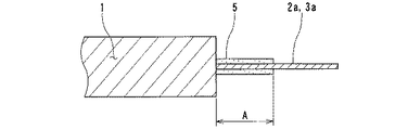
図3は実施例1に係る密閉型電池10aで使用した発電要素1の端子部を示す部分拡大断面図であり、図4は上記発電要素1を外装材4内に収容した密閉型電池の端子部の部分拡大断面図であり、この密閉型電池10aを以下の手順で調製した。すなわち、厚さが4mmである発電要素1を準備し、その発電要素1の厚さ方向の中央部に、厚さが0.1mmで幅が4mmのニッケル板から成る負極端子2aと、厚さが0.1mmであり幅が4mmのアルミニウム板からなる正極端子3aとを接続した。各端子2a,3aは厚さが0.1mmのポリプロピレンフィルム5が融着された部分を有しており、その部分の長さAは5mmであり、ポリプロピレンフィルム5は各端子2a,3aの全周を被覆している。そのポリプロピレンフィルム5である絶縁樹脂フィルムが融着された部分が、発電要素1から延出している端子2a,3aの根元に位置するように端子2a,3aを接続した。
[Example 1]
FIG. 3 is a partially enlarged cross-sectional view showing a terminal portion of the
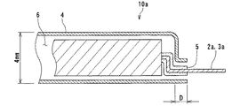
次に上記のように調製した発電要素1に接続した各端子2a,3aの基部を折り曲げて図4に示す実施例1に係る密閉型電池10aを調製した。すなわち、各端子2a,3aは、根元側の絶縁樹脂フィルム5の端部と、そのフィルム5の端部から下方に2mmの距離を置いた絶縁樹脂フィルム被覆部分で図4に示すように水平方向に折り曲げられる。しかる後に、発電要素1および電解液を、外装材4に形成された絞り成形部6に収納した。そして最後に絶縁樹脂フィルム5を被覆した各端子2a,3aの端部に、外装材4の封止縁を押圧し熱融着により封止することにより実施例1に係る密閉型電池10aを調製した。なお、絶縁樹脂フィルム5を被覆した各端子2a,3aと、外装材4の封止縁との熱融着幅Dは2mmとした。
Next, the base of each terminal 2a, 3a connected to the
[実施例2]
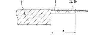
図5は実施例2に係る密閉型電池10bで使用した発電要素1の端子部を示す部分拡大断面図であり、図6は上記発電要素1を外装材4内に収容した密閉型電池10bの端子部の部分拡大断面図であり、この密閉型電池10bを以下の手順で調製した。すなわち、発電要素1の厚さは4mmとし、その発電要素1の同じ側の負極最外周と正極最外周に、ニッケル板からなる負極端子2bおよびアルミニウム板からなる正極端子3bをそれぞれ接続した。各端子2b、3bの寸法は厚さが0.1mmであり、幅は4mmとする一方、厚さが0.1mmのポリプロピレンフィルムが融着された部分の長さBは7mmとした。
[Example 2]
FIG. 5 is a partially enlarged cross-sectional view showing a terminal portion of the
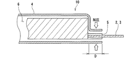
図6は実施例2に係る密閉型電池10bの端子部断面を示し、正負極端子2b、3bの折り曲げ位置を図示している。すなわち、絶縁樹脂フィルム5が融着された部分が発電要素1から延出している端子の根元が発電要素1の厚さ方向の頂部に位置するように端子2b、3bを接続し、この正負極端子2b、3bを折り曲げる位置は、根元側の絶縁樹脂フィルム端と、その根元の絶縁フィルム端から4mm下方の位置との2箇所とし、外装材4との封止のための融着幅Dは2mmとした。
FIG. 6 shows a cross section of the terminal portion of the sealed
[比較例]
図7は比較例に係る密閉型電池10で使用した発電要素1の端子部の断面図であり、この密閉型電池10を以下の手順で調製した。すなわち、発電要素の厚さは4mmとし、その発電要素1の同じ側の負極最外周と正極最外周(図8において発電要素1の最下部)に、ニッケル板からなる負極端子2とアルミニウム板からなる正極端子3とをそれぞれ接続した。各端子2,3の寸法は厚さが0.1mmであり、幅は4mmとする一方、厚さが0.1mmであるポリプロピレンフィルムが融着された部分の長さCは3mmとした。
[Comparative example]
FIG. 7 is a cross-sectional view of the terminal portion of the
図8は上記比較例に係る密閉型電池10の端子部の断面図を示す。外部端子2,3は折り曲げ加工を施すことなく、発電要素1の端子接続位置が融着面の延長線上になるように発電要素1を絞り成形部6に挿入すると共に、外装材4との融着幅Dは2mmに設定して融着することにより、比較例2に係る従来の密閉型電池10cを調製した。
FIG. 8 is a cross-sectional view of the terminal portion of the sealed
上記のように調製した各実施例および比較例に係る密閉型電池10,10a、10bをそれぞれ各100個試作し、それら電池の封止部の耐久性を評価するために、各電池を温度が45℃で相対湿度が90%に設定された恒温恒湿槽内に3ヶ月保管する耐久試験を実施した。そして、保管期間満了後において各実施例および比較例に係る密閉型電池を観察し、正負極端子と外装材との封止部(タブシール部)を経由した電池外部への電解液の漏洩の有無を検査した。また、シール部分において外装材が正負極端子から浮き上がって剥離する等の不具合を生じている電池の割合を計数して下記表1に示す結果を得た。

上記表1に示す結果から明らかなように、比較例に係る密閉型電池においては、100個の電池の全てについて、タブシール部が電池内側から剥がれ始めており、外部から見てシール部分の外装材が浮き上がっている状態が確認された。しかも、それらの電池のうち、タブシール部の剥離および浮き上がりがさらに進展したために、タブシール部(封止部)から電解液が外部に漏洩している電池が45個も確認された。これに対して、各実施例に係る密閉型電池では、液漏れを生じた電池は皆無であり、比較例の電池と比較して高い信頼性を有する電池であることが判明した。 As is clear from the results shown in Table 1 above, in the sealed battery according to the comparative example, the tab seal part has begun to peel off from the inside of the battery for all 100 batteries, and the exterior material of the seal part as viewed from the outside is A floating state was confirmed. In addition, among these batteries, peeling and lifting of the tab seal part further progressed, and 45 batteries in which the electrolyte leaked from the tab seal part (sealing part) were confirmed. On the other hand, in the sealed batteries according to the respective examples, no battery leaked liquid, and it was found that the battery had higher reliability than the battery of the comparative example.
また、実施例1の電池10aと実施例2の電池10bとを比較すると、両者とも電解液の漏洩を生じた電池は皆無であったが、シール部が剥離し始めている電池の割合は実施例2の方が少ないため、より信頼性は高いと言える。この結果より、電池内部の絶縁樹脂フィルムを融着した端子部分が長いほうが、よりシール信頼性および電池の耐久性を高める観点から有利であることが判明した。
Further, when the
[実施例3]
厚さが4mmである発電要素1の端面から正負極端子を導出する位置を、発電要素1の厚さ方向に0.5mm間隔で種々変化させて発電要素1から延出している正負極端子に絶縁樹脂フィルムが熱融着されている部分の電池内部における長さを変化させた点以外は実施例1と同様に組立て処理することにより、実施例3に係る密閉型電池を多数調製した。
[Example 3]
The position where the positive and negative terminals are led out from the end face of the
こうして調製した実施例3に係る密閉型電池について、実施例1と同様に、各電池を温度が45℃で相対湿度が90%に設定された恒温恒湿槽内に3ヶ月保管する耐久試験を実施した。そして、保管期間満了後において各密閉型電池を観察し、正負極端子と外装材との封止部(タブシール部)を経由した電池外部への電解液の漏洩の有無を検査した。 For the sealed battery according to Example 3 prepared in this way, as in Example 1, an endurance test was performed in which each battery was stored in a thermo-hygrostat set at a temperature of 45 ° C. and a relative humidity of 90% for 3 months. Carried out. Then, after the storage period expired, each sealed battery was observed, and the presence or absence of leakage of the electrolyte solution to the outside of the battery via the sealing portion (tab seal portion) between the positive and negative electrode terminals and the exterior material was inspected.
その結果、絶縁樹脂フィルムが熱融着されている端子部分であって発電要素の端面に沿って形成した端子部分の長さ(図6においてH)が2mm以上のときに、電解液の漏洩を皆無にできることが判明した。 As a result, when the length (H in FIG. 6) of the terminal portion formed along the end face of the power generation element is 2 mm or more, the electrolyte solution leaks when the insulating resin film is heat-sealed. It turns out that there can be none.
1 発電要素
2、2a、2b 負極端子(外部端子)
3、3a、3b 正極端子(外部端子)
4 外装材(金属ラミネート樹脂フィルム)
5 絶縁樹脂フィルム
6 絞り成形部
10、10a、10b 密閉型電池
1
3, 3a, 3b Positive terminal (external terminal)
4 Exterior material (metal laminate resin film)
5 Insulating
Claims (3)
Priority Applications (1)
| Application Number | Priority Date | Filing Date | Title |
|---|---|---|---|
| JP2004032326A JP4592297B2 (en) | 2004-02-09 | 2004-02-09 | Sealed battery |
Applications Claiming Priority (1)
| Application Number | Priority Date | Filing Date | Title |
|---|---|---|---|
| JP2004032326A JP4592297B2 (en) | 2004-02-09 | 2004-02-09 | Sealed battery |
Publications (2)
| Publication Number | Publication Date |
|---|---|
| JP2005222901A JP2005222901A (en) | 2005-08-18 |
| JP4592297B2 true JP4592297B2 (en) | 2010-12-01 |
Family
ID=34998352
Family Applications (1)
| Application Number | Title | Priority Date | Filing Date |
|---|---|---|---|
| JP2004032326A Expired - Fee Related JP4592297B2 (en) | 2004-02-09 | 2004-02-09 | Sealed battery |
Country Status (1)
| Country | Link |
|---|---|
| JP (1) | JP4592297B2 (en) |
Cited By (1)
| Publication number | Priority date | Publication date | Assignee | Title |
|---|---|---|---|---|
| KR101792605B1 (en) | 2014-12-08 | 2017-11-01 | 주식회사 엘지화학 | Secondary Battery Containing Sealing Member at the Electrode Tap-Lead Joint Portion |
Families Citing this family (8)
| Publication number | Priority date | Publication date | Assignee | Title |
|---|---|---|---|---|
| JP4821218B2 (en) * | 2005-09-01 | 2011-11-24 | 日本ケミコン株式会社 | Capacitor |
| WO2008016243A1 (en) * | 2006-07-31 | 2008-02-07 | Lg Chem, Ltd. | Secondary battery with top sealed portion of improved structure |
| JP5813480B2 (en) * | 2011-11-22 | 2015-11-17 | 株式会社ブリヂストン | Rubber composition for hose and hose |
| JP7165526B2 (en) * | 2017-09-28 | 2022-11-04 | マクセル株式会社 | electrochemical element |
| US10673028B2 (en) * | 2017-09-28 | 2020-06-02 | Maxwell Holdings, Ltd. | Electrochemical element |
| JP7016234B2 (en) * | 2017-09-29 | 2022-02-04 | 三洋化成工業株式会社 | Lithium ion battery |
| WO2021065339A1 (en) * | 2019-09-30 | 2021-04-08 | 株式会社村田製作所 | Secondary battery |
| CN113948825B (en) * | 2020-06-30 | 2023-09-05 | 比亚迪股份有限公司 | Battery cell and battery |
Citations (5)
| Publication number | Priority date | Publication date | Assignee | Title |
|---|---|---|---|---|
| JP2000138053A (en) * | 1998-10-30 | 2000-05-16 | Sony Corp | Nonaqueous electrolyte battery and its manufacture |
| JP2001052663A (en) * | 1999-08-12 | 2001-02-23 | Yuasa Corp | Battery |
| JP2001057183A (en) * | 1999-08-19 | 2001-02-27 | Nec Corp | Laminate film-sealed battery and manufacture thereof |
| JP2003168403A (en) * | 2001-11-30 | 2003-06-13 | Sony Corp | Lithium ion polymer battery and its manufacturing method |
| JP2003346768A (en) * | 2002-05-29 | 2003-12-05 | Japan Storage Battery Co Ltd | Non-aqueous electrolyte secondary battery |
-
2004
- 2004-02-09 JP JP2004032326A patent/JP4592297B2/en not_active Expired - Fee Related
Patent Citations (5)
| Publication number | Priority date | Publication date | Assignee | Title |
|---|---|---|---|---|
| JP2000138053A (en) * | 1998-10-30 | 2000-05-16 | Sony Corp | Nonaqueous electrolyte battery and its manufacture |
| JP2001052663A (en) * | 1999-08-12 | 2001-02-23 | Yuasa Corp | Battery |
| JP2001057183A (en) * | 1999-08-19 | 2001-02-27 | Nec Corp | Laminate film-sealed battery and manufacture thereof |
| JP2003168403A (en) * | 2001-11-30 | 2003-06-13 | Sony Corp | Lithium ion polymer battery and its manufacturing method |
| JP2003346768A (en) * | 2002-05-29 | 2003-12-05 | Japan Storage Battery Co Ltd | Non-aqueous electrolyte secondary battery |
Cited By (1)
| Publication number | Priority date | Publication date | Assignee | Title |
|---|---|---|---|---|
| KR101792605B1 (en) | 2014-12-08 | 2017-11-01 | 주식회사 엘지화학 | Secondary Battery Containing Sealing Member at the Electrode Tap-Lead Joint Portion |
Also Published As
| Publication number | Publication date |
|---|---|
| JP2005222901A (en) | 2005-08-18 |
Similar Documents
| Publication | Publication Date | Title |
|---|---|---|
| KR101216422B1 (en) | Secondary Battery Having Sealing Portion of Improved Insulating Property | |
| JP6681720B2 (en) | Electrochemical cell and method of manufacturing electrochemical cell | |
| JP5023391B2 (en) | Manufacturing method of laminated battery | |
| JP2010033922A (en) | Layered secondary battery | |
| JP2004356085A (en) | Jelly roll type electrode assembly and secondary battery adopting this | |
| JP2001102090A (en) | Fabrication method of plate type cell | |
| CN109564990B (en) | Electrochemical device | |
| JP5229440B2 (en) | Electrochemical devices | |
| JP4592297B2 (en) | Sealed battery | |
| JP2006351361A (en) | Film armor type power storage device | |
| WO2018016653A1 (en) | Electrochemical device | |
| JP2006164784A (en) | Film-armored electric device | |
| JP2000208110A (en) | Thin battery | |
| JP2009181899A (en) | Laminated battery | |
| JP4637305B2 (en) | Battery pack | |
| JP2005228573A (en) | Closed type battery | |
| JP2017126558A (en) | Electrochemical cell and manufacturing method of electrochemical cell | |
| JP5158435B2 (en) | Battery and manufacturing method thereof | |
| KR101546002B1 (en) | electrochemical energy storage device | |
| WO2004045006A1 (en) | Film-enclosed battery and battery assembly | |
| JP5093465B2 (en) | Non-aqueous electrolyte secondary battery | |
| JPH10284111A (en) | Manufacture of battery | |
| JP2006164863A (en) | Flat battery pack and method for manufacturing it | |
| JPH11219689A (en) | Thin type battery using laminate armoring | |
| JP2020072061A (en) | Electrochemical cell and manufacturing method thereof |
Legal Events
| Date | Code | Title | Description |
|---|---|---|---|
| A621 | Written request for application examination |
Free format text: JAPANESE INTERMEDIATE CODE: A621 Effective date: 20070206 |
|
| A977 | Report on retrieval |
Free format text: JAPANESE INTERMEDIATE CODE: A971007 Effective date: 20100624 |
|
| TRDD | Decision of grant or rejection written | ||
| A01 | Written decision to grant a patent or to grant a registration (utility model) |
Free format text: JAPANESE INTERMEDIATE CODE: A01 Effective date: 20100817 |
|
| A01 | Written decision to grant a patent or to grant a registration (utility model) |
Free format text: JAPANESE INTERMEDIATE CODE: A01 |
|
| A61 | First payment of annual fees (during grant procedure) |
Free format text: JAPANESE INTERMEDIATE CODE: A61 Effective date: 20100914 |
|
| FPAY | Renewal fee payment (event date is renewal date of database) |
Free format text: PAYMENT UNTIL: 20130924 Year of fee payment: 3 |
|
| R150 | Certificate of patent or registration of utility model |
Free format text: JAPANESE INTERMEDIATE CODE: R150 |
|
| LAPS | Cancellation because of no payment of annual fees |