JP4591663B2 - Side shim selection method and side shim selection device for differential carrier assembly - Google Patents

Side shim selection method and side shim selection device for differential carrier assembly Download PDF

Info

Publication number
JP4591663B2
JP4591663B2 JP2004194045A JP2004194045A JP4591663B2 JP 4591663 B2 JP4591663 B2 JP 4591663B2 JP 2004194045 A JP2004194045 A JP 2004194045A JP 2004194045 A JP2004194045 A JP 2004194045A JP 4591663 B2 JP4591663 B2 JP 4591663B2
Authority
JP
Japan
Prior art keywords
differential case
carrier
shaft
case subassembly
differential
Prior art date
Legal status (The legal status is an assumption and is not a legal conclusion. Google has not performed a legal analysis and makes no representation as to the accuracy of the status listed.)
Expired - Fee Related
Application number
JP2004194045A
Other languages
Japanese (ja)
Other versions
JP2006017183A (en
Inventor
宏明 田中
Current Assignee (The listed assignees may be inaccurate. Google has not performed a legal analysis and makes no representation or warranty as to the accuracy of the list.)
Toyota Motor Corp
Original Assignee
Toyota Motor Corp
Priority date (The priority date is an assumption and is not a legal conclusion. Google has not performed a legal analysis and makes no representation as to the accuracy of the date listed.)
Filing date
Publication date
Application filed by Toyota Motor Corp filed Critical Toyota Motor Corp
Priority to JP2004194045A priority Critical patent/JP4591663B2/en
Publication of JP2006017183A publication Critical patent/JP2006017183A/en
Application granted granted Critical
Publication of JP4591663B2 publication Critical patent/JP4591663B2/en
Expired - Fee Related legal-status Critical Current
Anticipated expiration legal-status Critical

Links

Images

Description

本発明は、ディファレンシャルキャリアアッセンブリのサイドシム選択方法及びサイドシム選択装置に関し、特に、ドライブピニオンギヤとリングギヤとのバックラッシュを調節するために組み込まれるサイドシムの厚さを選択する方法及び該サイドシムの厚さを選択するための装置に関する。   The present invention relates to a side shim selection method and a side shim selection device for a differential carrier assembly, and more particularly, a method for selecting a thickness of a side shim incorporated for adjusting backlash between a drive pinion gear and a ring gear, and selection of the thickness of the side shim. It is related with the apparatus for doing.

一般に、ディファレンシャルキャリアアッセンブリは、キャリアに回転可能に支持されるドライブピニオンシャフトの一端にドライブピニオンギヤが設けられて、該ドライブピニオンギヤに、デフケースサブアッセンブリのフランジに固定されるリングギヤが噛み合わされる。このようなディファレンシャルキャリアアッセンブリでは、ケースサブアッセンブリの両端の各軸部が、一対のサイドベアリングを介してキャリアに回転可能に支持される。また、ディファレンシャルキャリアアッセンブリでは、各サイドベアリングと当該各サイドベアリングが収容される各ベアリング支持部との間に各サイドシムが組み付けられて、各サイドシムの厚さが調節されることにより、ドライブピニオンギヤとリングギヤとのバックラッシュが調節される。そして、ドライブピニオンギヤとリングギヤとのバックラッシュを調節するに際して適正な厚みのサイドシムを選択するための様々な形態の技術がある。   Generally, in a differential carrier assembly, a drive pinion gear is provided at one end of a drive pinion shaft that is rotatably supported by the carrier, and a ring gear fixed to a flange of the differential case subassembly is meshed with the drive pinion gear. In such a differential carrier assembly, the shaft portions at both ends of the case subassembly are rotatably supported by the carrier via a pair of side bearings. Further, in the differential carrier assembly, each side shim is assembled between each side bearing and each bearing support portion in which each side bearing is accommodated, and the thickness of each side shim is adjusted, so that the drive pinion gear and the ring gear are adjusted. And backlash is adjusted. There are various forms of techniques for selecting a side shim having an appropriate thickness when adjusting the backlash between the drive pinion gear and the ring gear.

例えば、特許文献1には、デフケースサブアッセンブリが相対移動限度に近づく方向の一方のサイドベアリング組み付け端面とサイドベアリングアウターレースとの間に、デフケースサブアッセンブリが相対移動限度に達しないような厚さを有するマスターシムを配置して、該マスターシムを押圧するように荷重を負荷したときのデフケースサブアッセンブリの距離L2を計測する工程と、他方のサイドベアリング組み付け端面とサイドベアリングアウターレースとを押圧するように荷重を負荷したときのデフケースサブアッセンブリの距離L1を計測する工程と、デフケースサブアッセンブリが相対移動限度に達するように荷重を負荷したときのデフケースサブアッセンブリの距離L3を計測する工程と、を行い、ドライブピニオンギヤを1回転させた際の各距離L1,L2,L3の平均値を求めておいて、これら各距離L1,L2,L3の平均値に基づいてシムを選択するシム選択方法(以下、従来のシム選択方法と称す。)が開示されている。   For example, Patent Document 1 discloses a thickness that prevents the differential case subassembly from reaching the relative movement limit between the side bearing outer race and the side bearing assembly end surface in the direction in which the differential case subassembly approaches the relative movement limit. A step of measuring the distance L2 of the differential case subassembly when a load is applied so as to press the master shim, and the other side bearing assembly end surface and the side bearing outer race are pressed. A step of measuring the distance L1 of the differential case sub-assembly when a load is applied to the center, and a step of measuring the distance L3 of the differential case sub-assembly when the load is applied so that the differential case sub-assembly reaches a relative movement limit. Drive pinion gear A shim selection method for obtaining an average value of the distances L1, L2, and L3 at the time of rotation and selecting a shim based on the average values of the distances L1, L2, and L3 (hereinafter, a conventional shim selection method) Is disclosed).

しかしながら、上記従来のシム選択方法では、デフケースサブアッセンブリの各軸部の軸穴にシム選択装置の各センタリング軸がインローで嵌合されて、デフケースサブアッセンブリがシム選択装置に支持されるため、シム選択装置の各センタリング軸に対する、デフケースサブアッセンブリの軸中心線の相対位置が安定しない。これにより、各距離L1,L2,L3の繰り返しの測定値がばらついて、その結果、シム選択結果もばらつくことになる。また、従来のシム選択方法では、デフケースサブアッセンブリの軸中心線が、キャリアの各ベアリング支持部に対してオフセットされるが、デフケースサブアッセンブリがオフセットされる量は、シム選択装置並びに各構成要素の精度によってばらつきが生じるため、該ばらつきによってシム選択結果がばらついて、適正なサイドシムを選択することが困難になる。
特開平11−182653号公報(段落番号0012〜0026、図3)
However, in the above-described conventional shim selection method, each centering shaft of the shim selection device is fitted in the shaft hole of each shaft portion of the differential case subassembly with an inlay, and the differential case subassembly is supported by the shim selection device. The relative position of the shaft center line of the differential case subassembly with respect to each centering shaft of the selection device is not stable. As a result, repeated measurement values of the distances L1, L2, and L3 vary, and as a result, shim selection results also vary. Further, in the conventional shim selection method, the axial center line of the differential case subassembly is offset with respect to each bearing support portion of the carrier. The amount by which the differential case subassembly is offset depends on the shim selection device and each component. Since variations occur depending on the accuracy, shim selection results vary due to the variations, making it difficult to select an appropriate side shim.
JP-A-11-182653 (paragraph numbers 0012 to 0026, FIG. 3)

そこで本発明は、上記事情に鑑みてなされたもので、第1の目的は、適正なサイドシムを選択することが可能なディファレンシャルキャリアアッセンブリのサイドシム選択方法を提供することにある。第2の目的は、適正なサイドシムを選択することが可能なディファレンシャルキャリアアッセンブリのサイドシム選択装置を提供することにある。   Therefore, the present invention has been made in view of the above circumstances, and a first object is to provide a side shim selection method for a differential carrier assembly capable of selecting an appropriate side shim. The second object is to provide a side shim selection device for a differential carrier assembly that can select an appropriate side shim.

上記第1の目的を達成するために、本発明のうち請求項1に記載の発明は、ディファレンシャルキャリアアッセンブリの相互に噛み合わされるドライブピニオンギヤとリングギヤとのバックラッシュを調節するに際して、キャリアに配設されてデフケースサブアッセンブリの両端の軸部を支持する各軸支部のうち、該デフケースサブアッセンブリの反フランジ側の第1の軸部を支持する第1の軸支部に組み付けられる第1のサイドシムの厚さと、前記デフケースサブアッセンブリのフランジ側の第2の軸部を支持する第2の軸支部に組み付けられる第2のサイドシムの厚さと、が選択されるディファレンシャルキャリアアッセンブリのサイドシム選択方法であって、前記第1の軸支部に第1のマスタシムが組み付けられると共に前記第2の軸支部に第2のマスタシムが組み付けられるステップと、前記デフケースサブアッセンブリが芯出しされて軸中心線の回りに回転可能に支持されるステップと、前記第1の軸部に装着された第1のサイドベアリングのアウタレース外側面にスラスト方向のベアリング与圧を作用させつつ、前記ドライブピニオンギヤを回転駆動させた後、前記デフケースサブアッセンブリの、前記リングギヤの1回転当りの前記キャリアに対する軸中心線方向への変位の平均値L1が測定されるステップと、前記第2の軸部に装着された第2のサイドベアリングのアウタレース外側面にスラスト方向のベアリング与圧を作用させつつ、前記ドライブピニオンギヤを回転駆動させた後、前記デフケースサブアッセンブリの、前記リングギヤの1回転当りの前記キャリアに対する軸中心線方向への変位の平均値L2が測定されるステップと、前記第1の軸支部から前記第1のマスタシムが取り外されると共に前記第2の軸支部から前記第2のマスタシムが取り外されるステップと、各マスタシムが取り外された後、前記第1のサイドベアリングのアウタレース外側面にスラスト方向のベアリング与圧を作用させて、前記ドライブピニオンギヤと前記リングギヤとをノンバックにして、この状態で、前記ドライブピニオンギヤを回転駆動させて、前記デフケースサブアッセンブリの、前記リングギヤの1回転当りの前記キャリアに対する軸中心線方向への変位の平均値L3が測定されるステップと、の各ステップを含んで構成されて、測定された各平均値L1,L2,L3に基づいて各サイドシムの厚さが選択されることを特徴とする。
In order to achieve the first object, the invention according to claim 1 of the present invention is arranged on the carrier when adjusting the backlash between the drive pinion gear and the ring gear engaged with each other in the differential carrier assembly. The thickness of the first side shim that is assembled to the first shaft support portion that supports the first shaft portion on the opposite side of the differential case subassembly among the shaft support portions that support the shaft portions at both ends of the differential case subassembly. Sato, a Saidoshimu selection method of the differential carrier assembly and the thickness of the second Saidoshimu assembled to a second shaft support for supporting the second shaft portion of the flange side of the differential case subassembly, is selected, the the second axis together with the first Masutashimu is assembled to the first shaft support A step of second Masutashimu is assembled to part, the steps of the differential case subassembly is supported rotatably around the axial center line is centered, the first side attached to the first shaft portion while the action of the thrust direction of the bearing pressurizing the outer race outer surface of the bearing, said after the drive pinion gear is rotated, the differential case subassembly, the displacement in the axial center line direction relative to the carrier per revolution of the ring gear a step of average value L1 of is measured, while the action of the thrust direction of the bearing pressurizing the outer race outer surface of the second side bearing mounted on the second shaft portion, and is driven to rotate the drive pinion gear after, the differential case subassembly, the calibration of one rotation per the ring gear A step of average value L2 of the displacement in the axial center line direction is measured with respect to A, wherein the first shaft supporting said from the first and the second shaft support with Masutashimu is removed second Masutashimu is removed and steps, after each Masutashimu is removed, the outer race outer surface of the first side bearing by the action of the thrust direction of the bearing preload, and the said ring gear and said drive pinion gear to the non-back, in the state , said drive pinion gear is rotated, said differential case subassembly, comprising the steps of mean value L3 of the displacement in the axial center line direction is measured with respect to the carrier of one rotation per the ring gear, the steps of Configured and selected thickness of each side shim based on each measured average value L1, L2, L3 It is characterized by being.

請求項2に記載の発明は、請求項1に記載のディファレンシャルキャリアアッセンブリのサイドシム選択方法において、相互に近接離反可能な一対のセンタリングコーンがデフケースサブアッセンブリの各軸部に形成された各軸穴に係合されることにより、デフケースサブアッセンブリが芯出しされて軸中心線の回りに回転可能に支持されることを特徴とする。
請求項3に記載の発明は、請求項1又は2に記載のディファレンシャルキャリアアッセンブリのサイドシム選択方法において、キャリアの各軸支部が各軸支部の半径方向へ2分割されて形成されて、一対のセンタリングコーンがデフケースサブアッセンブリの各軸部に形成された各軸穴に係合されることにより、デフケースサブアッセンブリが各軸支部の軸線に対して各軸支部の分割方向へ所定距離だけオフセットされることを特徴とする。
請求項4に記載の発明は、請求項1〜3のいずれかに記載のディファレンシャルキャリアアッセンブリのサイドシム選択方法において、デフケースサブアッセンブリが芯出しされた状態で、該デフケースサブアッセンブリの軸中心線と一端にドライブピニオンギヤが取り付けられたドライブピニオンシャフトの他端の端面との距離が測定されて、該測定結果に基づいてドライブピニオンギヤの取付基準位置とキャリアの各軸支部の軸線との間の距離が導出されて、ドライブピニオンギヤの取付基準位置とキャリアの各軸支部の軸線との間の距離に基づいて、ドライブピニオンギヤとリングギヤとの歯当りが評価されることを特徴とする。
According to a second aspect of the present invention, in the differential carrier assembly side shim selection method according to the first aspect, a pair of centering cones that can be moved closer to and away from each other are provided in each shaft hole formed in each shaft portion of the differential case subassembly. By engaging, the differential case sub-assembly is centered and supported so as to be rotatable around the axial center line.
A third aspect of the present invention is the differential carrier assembly side shim selection method according to the first or second aspect, wherein each shaft support portion of the carrier is formed by being divided into two in the radial direction of each shaft support portion. When the cone is engaged with each shaft hole formed in each shaft portion of the differential case subassembly, the differential case subassembly is offset by a predetermined distance in the dividing direction of each shaft support portion with respect to the axis of each shaft support portion. It is characterized by.
The invention according to claim 4 is the differential carrier assembly side shim selection method according to any one of claims 1 to 3, wherein the differential case subassembly is centered and the axial center line and one end of the differential case subassembly are centered. The distance from the other end face of the drive pinion shaft to which the drive pinion gear is mounted is measured, and the distance between the drive pinion gear mounting reference position and the axis of each shaft support portion of the carrier is derived based on the measurement result. Then, the contact between the drive pinion gear and the ring gear is evaluated based on the distance between the reference mounting position of the drive pinion gear and the axis of each shaft support portion of the carrier.

上記第2の目的を達成するために、本発明のうち請求項5に記載の発明は、請求項1〜4に記載のディファレンシャルキャリアアッセンブリのサイドシム選択方法に用いられるディファレンシャルキャリアアッセンブリのサイドシム選択装置であって、デフケースサブアッセンブリの両端の軸部を支持するキャリアの各軸支部に必要に応じて組み付けられるマスタシムと、デフケースサブアッセンブリが組み付けられたキャリアが正規位置に位置決め固定されるキャリア固定手段と、該キャリア固定手段によりキャリアが位置決め固定された状態で、デフケースサブアッセンブリが芯出しされて軸中心線の回りに回転可能に支持される支持手段と、該支持手段によって支持されたデフケースサブアッセンブリの両端の軸部に装着された一対のサイドベアリングにスラスト方向のベアリング与圧を作用させるベアリング与圧手段と、ドライブピニオンギヤが回転駆動されて該ドライブピニオンギヤに噛み合わされるリングギヤが回転される駆動手段と、デフケースサブアッセンブリのキャリアに対する軸中心線方向への変位が測定される第1の測定手段と、該第1の測定手段の測定結果が演算処理されて、キャリアの反フランジ側の第1の軸支部に組み付けられる第1のサイドシムの厚さとフランジ側の第2の軸支部に組み付けられる第2のサイドシムの厚さとが出力される演算手段と、を具備するサイドシム選択装置によって、第1のサイドシムの厚さと第2のサイドシムの厚さとが選択されることを特徴とする。   In order to achieve the second object, the invention according to claim 5 of the present invention is a differential carrier assembly side shim selection device used in the differential carrier assembly side shim selection method according to claims 1 to 4. A master shim that is assembled to each shaft support portion of the carrier that supports the shaft portions at both ends of the differential case subassembly, and carrier fixing means for positioning and fixing the carrier in which the differential case subassembly is assembled at a normal position; With the carrier fixed by the carrier fixing means, the differential case subassembly is centered and supported so as to be rotatable around the axis center line, and both ends of the differential case subassembly supported by the support means A pair of attached to the shaft Bearing pressurizing means for applying thrust in the thrust direction to the id bearing, drive means for rotating the drive pinion gear to rotate the ring gear meshed with the drive pinion gear, and the shaft center line with respect to the carrier of the differential case subassembly The first measuring means for measuring the displacement in the direction, and the thickness of the first side shim assembled to the first shaft support on the opposite side of the carrier after the measurement result of the first measuring means is processed And calculating means for outputting the thickness of the second side shim assembled to the second shaft support on the flange side, the thickness of the first side shim and the thickness of the second side shim is obtained by the side shim selection device. It is selected.

請求項6に記載の発明は、請求項5に記載のディファレンシャルキャリアアッセンブリのサイドシム選択装置において、支持手段が、デフケースサブアッセンブリの両端の軸部に形成された各軸穴に係合されて相互に近接離反される一対のセンタリングコーンを備えることを特徴とする。
請求項7に記載の発明は、請求項5又は6に記載のディファレンシャルキャリアアッセンブリのサイドシム選択装置において、キャリアの各軸支部が各軸支部の半径方向へ2分割されて形成されて、デフケースサブアッセンブリが各軸支部の軸線に対して各軸支部の分割方向へ所定距離だけオフセットされるオフセット手段を備えることを特徴とする。
請求項8に記載の発明は、請求項5〜7のいずれかに記載のディファレンシャルキャリアアッセンブリのサイドシム選択装置において、支持手段によって支持されたデフケースサブアッセンブリの軸中心線と一端にドライブピニオンギヤが取り付けられたドライブピニオンシャフトの他端の端面との距離が測定される第2の測定手段を備えて、該第2の測定手段の測定結果に基づいて導出されるドライブピニオンギヤの取付基準位置とキャリアの各軸支部の軸線との間の距離に基づいて、ドライブピニオンギヤとリングギヤとの歯当りが評価されることを特徴とする。
According to a sixth aspect of the present invention, in the side shim selection device for the differential carrier assembly according to the fifth aspect, the support means is engaged with the respective shaft holes formed in the shaft portions at both ends of the differential case subassembly so as to mutually It is characterized by comprising a pair of centering cones that are brought close to and away from.
According to a seventh aspect of the present invention, in the side shim selection device for a differential carrier assembly according to the fifth or sixth aspect, each shaft support portion of the carrier is formed by being divided into two in the radial direction of each shaft support portion. Is provided with offset means that is offset by a predetermined distance in the dividing direction of each shaft support with respect to the axis of each shaft support.
According to an eighth aspect of the present invention, in the differential carrier assembly side shim selection device according to any one of the fifth to seventh aspects , a drive pinion gear is attached to the axial center line and one end of the differential case subassembly supported by the support means. Each of the reference position of the drive pinion gear and the carrier derived from the measurement result of the second measurement means, the second measurement means measuring the distance from the other end face of the drive pinion shaft . The tooth contact between the drive pinion gear and the ring gear is evaluated based on the distance between the shaft support and the axis.

したがって、請求項1に記載の発明では、デフケースサブアッセンブリが芯出しされて軸中心線の回りに回転可能に支持される。この状態でドライブピニオンギヤが回転駆動されて、デフケースサブアッセンブリの、リングギヤの1回転当りのキャリアに対する軸中心線方向への変位の平均値L1,L2,L3が測定される。そして、各平均値L1,L2,L3に基づいて各サイドシムの厚さT1,T2が選択される。
請求項2に記載の発明では、一対のセンタリングコーンがデフケースサブアッセンブリの各軸部の軸穴に係合されることにより、デフケースサブアッセンブリが芯出しされて軸中心線の回りに回転可能に支持される。
請求項3に記載の発明では、一対のセンタリングコーンがデフケースサブアッセンブリの各軸部の軸穴に係合されることにより、該デフケースサブアッセンブリがキャリアの各軸支部の軸線に対して各軸支部の分割方向へ所定距離だけオフセットされる。
請求項4に記載の発明では、デフケースサブアッセンブリの軸中心線と一端にドライブピニオンギヤが取り付けられたドライブピニオンシャフトの他端の端面との距離に基づいて、ドライブピニオンギヤの取付基準位置(PMD基準)とキャリアの各軸支部の軸線との間の距離PMD(Pinion Mount Distance)が導出される。そして、導出された距離PMDに基づいて、ドライブピニオンギヤとリングギヤとの歯当りが評価される。
Therefore, in the first aspect of the present invention, the differential case subassembly is centered and supported so as to be rotatable around the axial center line. In this state, the drive pinion gear is driven to rotate, and average values L1, L2, and L3 of the displacement of the differential case subassembly in the axial center line direction with respect to the carrier per rotation of the ring gear are measured. Then, the thicknesses T1 and T2 of the side shims are selected based on the average values L1, L2, and L3.
In the second aspect of the present invention, the pair of centering cones are engaged with the shaft holes of the respective shaft portions of the differential case subassembly, so that the differential case subassembly is centered and supported so as to be rotatable around the axial center line. Is done.
According to the third aspect of the present invention, the pair of centering cones are engaged with the shaft holes of the respective shaft portions of the differential case subassembly so that the differential case subassembly is supported by the respective shaft support portions with respect to the axes of the respective shaft support portions of the carrier. Is offset by a predetermined distance in the dividing direction.
According to the fourth aspect of the present invention, the drive pinion gear mounting reference position (PMD reference) is based on the distance between the axial center line of the differential case subassembly and the other end face of the drive pinion shaft to which the drive pinion gear is mounted at one end. And a PMD (Pinion Mount Distance) between each axis of the carrier and the axis of each carrier. Based on the derived distance PMD, the contact between the drive pinion gear and the ring gear is evaluated.

請求項5に記載の発明では、キャリア固定手段によって、デフケースサブアッセンブリが組み付けられたキャリアが正規位置に位置決め固定される。また、キャリア固定手段によってキャリアが位置決め固定された状態で、支持手段によって、デフケースサブアッセンブリが芯出しされると共に回転可能に支持される。さらに、ベアリング与圧手段によって、一対のサイドベアリングにスラスト方向のベアリング与圧が作用されて、駆動手段によって、ドライブピニオンギヤが回転駆動されて該ドライブピニオンギヤに噛み合わされるリングギヤが回転される。そして、第1の測定手段によって、デフケースサブアッセンブリの、キャリアに対する軸中心線方向への変位が測定されて、演算手段によって、第1の測定手段の測定結果が演算処理されて第1のサイドシムの厚さと第2のサイドシムの厚さとが選択される。   According to the fifth aspect of the present invention, the carrier to which the differential case subassembly is assembled is positioned and fixed at the normal position by the carrier fixing means. In addition, the differential case subassembly is centered and supported rotatably by the support means while the carrier is positioned and fixed by the carrier fixing means. Further, a bearing pressure in the thrust direction is applied to the pair of side bearings by the bearing pressurization means, and the drive pinion gear is rotationally driven by the drive means to rotate the ring gear engaged with the drive pinion gear. Then, the displacement of the differential case subassembly in the axial center line direction with respect to the carrier is measured by the first measuring means, and the measurement result of the first measuring means is calculated by the calculating means to calculate the first side shim. The thickness and the thickness of the second side shim are selected.

請求項6に記載の発明では、一対のセンタリングコーンがデフケースサブアッセンブリの各軸部の軸穴に係合されることにより、デフケースサブアッセンブリが芯出しされて軸中心線の回りに回転可能に支持される。
請求項7に記載の発明では、オフセット手段によって、デフケースサブアッセンブリがキャリアの各軸支部の軸線に対して当該軸支部の分割方向へ所定距離だけオフセットされる。
請求項8に記載の発明では、第2の測定手段によって、デフケースサブアッセンブリの軸中心線と一端にドライブピニオンギヤが取り付けられたドライブピニオンシャフトの他端の端面との距離が測定されて、該第2の測定手段の測定結果に基づいて、ドライブピニオンギヤの取付基準位置(PMD基準)とキャリアの各軸支部の軸線との間の距離PMD(Pinion Mount Distance)が導出される。そして、導出された距離PMDに基づいて、ドライブピニオンギヤとリングギヤとの歯当りが評価される。
According to the sixth aspect of the present invention, the pair of centering cones are engaged with the shaft holes of the respective shaft portions of the differential case subassembly, so that the differential case subassembly is centered and supported so as to be rotatable around the axial center line. Is done.
According to the seventh aspect of the present invention, the differential case subassembly is offset by a predetermined distance in the dividing direction of the shaft support portion with respect to the axis of each shaft support portion of the carrier by the offset means.
In the invention according to claim 8, the second measuring means measures the distance between the axial center line of the differential case sub-assembly and the end face of the other end of the drive pinion shaft having the drive pinion gear attached to one end thereof. Based on the measurement result of the second measuring means, a distance PMD (Pinion Mount Distance) between the drive pinion gear mounting reference position (PMD reference) and the axis of each shaft support of the carrier is derived. Based on the derived distance PMD, the contact between the drive pinion gear and the ring gear is evaluated.

適正なサイドシムが選択されるディファレンシャルキャリアアッセンブリのサイドシム選択方法が提供される。
また、適正なサイドシムが選択されるディファレンシャルキャリアアッセンブリのサイドシム選択装置が提供される。
A method for selecting a side shim of a differential carrier assembly in which an appropriate side shim is selected is provided.
Further, a side shim selection device for a differential carrier assembly in which an appropriate side shim is selected is provided.

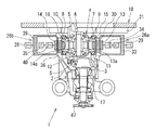
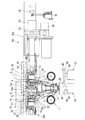
本発明の一実施の形態を図1〜図8に基づいて説明する。図1に示されるように、本ディファレンシャルキャリアアッセンブリ1のサイドシム選択方法は、キャリア2に組み付けられるドライブピニオンギヤ3と、デフケースサブアッセンブリ4のフランジ5に固定されるリングギヤ6と、が噛み合わされたディファレンシャルキャリアアッセンブリ1における、当該ドライブピニオンギヤ3とリングギヤ6とのバックラッシュを調節するに際して、上記デフケースサブアッセンブリ4の両端(図1における紙面視左右両側)の軸部7,8に嵌着される各サイドベアリング9,10が支持されるキャリア2の各ベアリング支持部11,12(軸支部)のうち、反フランジ側(図1における紙面視右側)の第1の軸部7に装着される第1のサイドベアリング9が支持される第1のベアリング支持部11に組み付けられる第1のサイドシムの厚さT1と、フランジ側(図1における紙面視左側)の第2の軸部8に装着される第2のサイドベアリング10が支持される第2のベアリング支持部12に組み付けられる第2のサイドシムの厚さT2と、を選択するものである。   An embodiment of the present invention will be described with reference to FIGS. As shown in FIG. 1, the side shim selection method of the differential carrier assembly 1 is a differential carrier in which a drive pinion gear 3 assembled to a carrier 2 and a ring gear 6 fixed to a flange 5 of a differential case subassembly 4 are engaged with each other. When adjusting the backlash between the drive pinion gear 3 and the ring gear 6 in the assembly 1, the side bearings fitted to the shaft portions 7 and 8 at both ends (left and right sides in FIG. 1) of the differential case subassembly 4. Of the bearing support portions 11 and 12 (shaft support portions) of the carrier 2 on which 9 and 10 are supported, the first side mounted on the first shaft portion 7 on the side opposite to the flange (right side in the drawing in FIG. 1). 1st bearing support part 11 with which bearing 9 is supported The thickness T1 of the first side shim to be assembled and the second bearing support portion 12 on which the second side bearing 10 mounted on the second shaft portion 8 on the flange side (left side in FIG. 1) is supported. The thickness T2 of the second side shim to be assembled to is selected.

また、図1に示されるように、本サイドシム選択方法では、キャリア2の各ベアリング支持部11,12に各マスタシム15,16が組み付けられて、デフケースサブアッセンブリ4の各軸部7,8の軸穴の開口端部が、同一の軸線C1(図6参照)上に配設されて該軸線C1の回りに回転可能な一対の支持部材13,14(センタリングコーン)のコーン部13a,14aによって押圧される。これにより、デフケースサブアッセンブリ4の軸中心線が一対の支持部材13,14の軸線C1に一致されて、当該デフケースサブアッセンブリ4が芯出しされると共に軸中心線(一対の支持部材13,14の軸線C1)の回りに回転可能に支持される。そして、この状態で、第1のサイドベアリング9のアウタレース外側面にスラスト方向(図1における紙面視左方向)のベアリング与圧を作用させつつドライブピニオンギヤ3を回転駆動させてドライブピニオンギヤ3とリングギヤ6とを調和させた後、デフケースサブアッセンブリ4の、リングギヤ6の1回転当りのキャリア2に対する軸中心線方向(図1における紙面視左右方向)への変位の平均値L1(以下、変位L1と称す。)が測定される。   Further, as shown in FIG. 1, in this side shim selection method, the master shims 15 and 16 are assembled to the bearing support portions 11 and 12 of the carrier 2, and the shaft portions 7 and 8 of the differential case subassembly 4 are shafts. Open end portions of the holes are pressed by cone portions 13a and 14a of a pair of support members 13 and 14 (centering cones) disposed on the same axis C1 (see FIG. 6) and rotatable about the axis C1. Is done. As a result, the axial center line of the differential case subassembly 4 is aligned with the axial line C1 of the pair of support members 13 and 14, the differential case subassembly 4 is centered, and the axial center line (of the pair of support members 13 and 14) is aligned. It is supported so as to be rotatable about an axis C1). In this state, the drive pinion gear 3 and the ring gear 6 are rotated by rotating the drive pinion gear 3 while applying a bearing pressure in the thrust direction (left direction as viewed in the drawing in FIG. 1) to the outer race outer surface of the first side bearing 9. After that, the average value L1 (hereinafter referred to as displacement L1) of the displacement of the differential case subassembly 4 in the axial center line direction (left-right direction in FIG. 1) relative to the carrier 2 per rotation of the ring gear 6 is determined. .) Is measured.

また、本サイドシム選択方法では、第2のサイドベアリング10のアウタレース外側面にスラスト方向(図1における紙面視右方向)のベアリング与圧を作用させつつドライブピニオンギヤ3を回転駆動させてドライブピニオンギヤ3とリングギヤ6とを調和させた後、デフケースサブアッセンブリ4の、リングギヤ6の1回転当りのキャリア2に対する軸中心線方向(図1における紙面視左右方向)への変位の平均値L2(以下、変位L2と称す。)が測定される。さらに、本サイドシム選択方法では、各ベアリング支持部11,12から各マスタシム15,16が取り外された後、ドライブピニオンギヤ3とリングギヤ6とがノンバックにされて、この状態で、当該ドライブピニオンギヤ3が回転駆動されて、デフケースサブアッセンブリ4の、リングギヤ6の1回転当りのキャリア2に対する軸中心線方向(図1における紙面視左右方向)への変位の平均値L3(以下、変位L3と称す。)が測定される。そして、本サイドシム選択方法では、上記各変位L1,L2,L3に基づいて、第1のベアリング支持部11に組み付けられるサイドシムの厚さT1と、第2のベアリング支持部12に組み付けられるサイドシムの厚さT2と、が選択される。   Further, in this side shim selection method, the drive pinion gear 3 is driven to rotate while the bearing pressure in the thrust direction (right direction in the drawing in FIG. 1) is applied to the outer race outer surface of the second side bearing 10. After harmonizing with the ring gear 6, the average value L2 (hereinafter referred to as the displacement L2) of displacement of the differential case subassembly 4 with respect to the carrier 2 per rotation of the ring gear 6 in the axial center line direction (left and right direction in FIG. 1). Is measured). Further, in this side shim selection method, after the master shims 15 and 16 are removed from the bearing support portions 11 and 12, the drive pinion gear 3 and the ring gear 6 are non-backed. In this state, the drive pinion gear 3 An average value L3 (hereinafter referred to as displacement L3) of the displacement of the differential case subassembly 4 in the axial centerline direction (left and right direction in the drawing in FIG. 1) relative to the carrier 2 per rotation of the ring gear 6 by being rotationally driven. Is measured. In this side shim selection method, the side shim thickness T1 assembled to the first bearing support portion 11 and the side shim thickness assembled to the second bearing support portion 12 based on the displacements L1, L2, and L3. T2 is selected.

図1に示されるように、本ディファレンシャルキャリアアッセンブリ1は、ドライブピニオンシャフト17が軸線方向(図1における紙面視上下方向)に配置された一対のベアリングを介してキャリア2に回転可能に支持されて、該ドライブピニオンシャフト17の一端に、上記ドライブピニオンギヤ3が設けられる。また、本ディファレンシャルキャリアアッセンブリ1は、デフケースサブアッセンブリ4の各軸部7,8に各サイドベアリング9,10のインナレースが嵌着されると共に、各サイドベアリング9,10のアウタレースがキャリア2の各ベアリング支持部11,12に嵌合される。なお、上記キャリア2は、各ベアリング支持部11,12が、軸平面で上下方向(図1における紙面視上下方向)に2分割されて形成されており、サイドシム選択時には、各ベアリング支持部11,12のいずれかの分割された部分(図1における紙面視上側の部分)が内周面に形成された各キャップが、キャリア2から取り外された状態にある。この状態(各キャップが取り外された状態)では、デフケースサブアッセンブリ4がキャリア2に対して上下方向(図1における紙面視上下方向)へ着脱可能である。   As shown in FIG. 1, the differential carrier assembly 1 is rotatably supported by a carrier 2 via a pair of bearings in which a drive pinion shaft 17 is arranged in an axial direction (up and down direction in the drawing in FIG. 1). The drive pinion gear 3 is provided at one end of the drive pinion shaft 17. In the differential carrier assembly 1, the inner races of the side bearings 9 and 10 are fitted on the shafts 7 and 8 of the differential case subassembly 4, and the outer races of the side bearings 9 and 10 are connected to the carrier 2. The bearing support portions 11 and 12 are fitted. The carrier 2 is formed by dividing the bearing support portions 11 and 12 into two in the vertical direction (vertical direction in the drawing in FIG. 1) on the axial plane. When the side shim is selected, the bearing support portions 11 and 12 are formed. Each of the caps in which any of the 12 divided portions (portion on the upper side in FIG. 1 in FIG. 1) is formed on the inner peripheral surface is in a state of being removed from the carrier 2. In this state (a state in which each cap is removed), the differential case subassembly 4 can be attached to and detached from the carrier 2 in the up-down direction (up-down direction in the drawing in FIG. 1).

そして、図5に示されるように、本サイドシム選択方向では、一対の支持部材13,14によってデフケースサブアッセンブリ4が芯出しされることにより、当該デフケースサブアッセンブリ4(支持部材13,14)の軸中心線が、キャリア2のベアリング支持部11,12の軸線C2(図6参照)に対して、所定距離(本実施の形態では1mm)だけ上方(図1における紙面視上方)へオフセットされて配置される構造(オフセット手段)になっている。これにより、本サイドシム選択方法では、キャリア2に対するデフケースサブアッセンブリ4の軸中心線方向への変位が測定されるに際して、デフケースサブアッセンブリ4の各軸部に装着された各サイドベアリング9,10が、キャリア2に配設された各ベアリング支持部11,12に対して容易に変位される。なお、上記デフケースサブアッセンブリ4には、軸部7,8と同一軸線上に配設された一対のサイドギヤと、軸部7,8に対して直交されるピニオンシャフトによって回転可能に軸支されて一対のサイドギヤに噛み合わされた一対のピニオンギヤと、が収容される。   As shown in FIG. 5, in the side shim selection direction, the differential case subassembly 4 is centered by the pair of support members 13 and 14, whereby the shaft of the differential case subassembly 4 (support members 13 and 14). The center line is offset from the axis C2 (see FIG. 6) of the bearing support portions 11 and 12 of the carrier 2 by a predetermined distance (1 mm in the present embodiment) upward (upward as viewed in FIG. 1). This is a structure (offset means). Thus, in this side shim selection method, when the displacement in the axial center line direction of the differential case subassembly 4 relative to the carrier 2 is measured, the side bearings 9 and 10 attached to the respective shaft portions of the differential case subassembly 4 are It is easily displaced with respect to the respective bearing support portions 11 and 12 arranged on the carrier 2. The differential case subassembly 4 is rotatably supported by a pair of side gears disposed on the same axis as the shaft portions 7 and 8 and a pinion shaft orthogonal to the shaft portions 7 and 8. A pair of pinion gears meshed with the pair of side gears are accommodated.

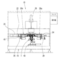
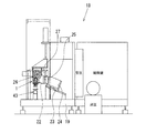
図2〜図4に示されるのは、デフケースサブアッセンブリ4の、リングギヤ6の1回転当りのキャリア2に対する軸中心線方向(図2及び図3における紙面視左右方向)への変位の各変位L1,L2,L3が測定されて、各変位L1,L2,L3に基づいて、第1のサイドシムの厚さT1と第2のサイドシムの厚さT2とが選択されるサイドシム選択装置18である。本サイドシム選択装置18は、本体フレーム19の上部に流体圧シリンダ20の駆動により昇降される押圧部材21(図1参照、キャリア固定手段。)が設けられて、該押圧部材21を下降させて当該押圧部材21の下面に突設された複数本の各ピンをキャリア2の所定位置に係合させることにより、ディファレンシャルキャリアアッセンブリ1が当該サイドシム選択装置18に対して正規位置に位置決め固定される。また、本サイドシム選択装置18は、本体フレーム19に対して左右方向(図2及び図3における紙面視左右方向)へスライド移動可能に設けられるユニットベース22を備える。   2 to 4 show each displacement L1 of the displacement of the differential case subassembly 4 in the axial center line direction (left and right direction in FIG. 2 and FIG. 3) with respect to the carrier 2 per rotation of the ring gear 6. , L2 and L3 are measured, and the first side shim thickness T1 and the second side shim thickness T2 are selected based on the respective displacements L1, L2 and L3. The side shim selection device 18 is provided with a pressing member 21 (see FIG. 1, carrier fixing means) that is moved up and down by driving the fluid pressure cylinder 20 at the upper part of the main body frame 19. The differential carrier assembly 1 is positioned and fixed at a normal position with respect to the side shim selection device 18 by engaging a plurality of pins protruding from the lower surface of the pressing member 21 at predetermined positions of the carrier 2. Further, the side shim selection device 18 includes a unit base 22 provided so as to be slidable in the left-right direction (left-right direction as viewed in FIG. 2 and FIG. 3) with respect to the main body frame 19.

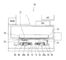
図4に示されるように、上記本体ベース19には、前後方向(図4における紙面視左右方向)へ傾斜される直動ガイド23を介して進退ベース24が設けられて、該進退ベース24には、左右方向(図4における紙面視方向)へ延びる直動ガイド25を介して上記ユニットベース22が設けられる。そして、該ユニットベース22の左右両側には、それぞれ測定ユニット26が配設される。なお、図3に示されるように、本サイドシム選択装置18は、前面視で左側(図3における紙面視左側)に配設される測定ユニット26b(以下、第2の測定ユニット26bと称す。)が、直動ガイド27を介して上記ユニットベース22に設けられて、流体圧シリンダ28によって左右方向(図2及び図3における紙面視左右方向)へ直動駆動されることにより、前面視で右側に配設される測定ユニット26a(以下、第1の測定ユニット26aと称す。)に対して近接離反される。図5に示されるように、第1の測定ユニット26aには、外円錐面を有するコーン部13aが先端に形成された支持部材13が軸線C1の回りに回転可能に設けられる。   As shown in FIG. 4, the main body base 19 is provided with an advancing / retreating base 24 via a linear motion guide 23 that is inclined in the front-rear direction (left-right direction in FIG. 4). The unit base 22 is provided through a linear motion guide 25 extending in the left-right direction (the direction of the paper in FIG. 4). Measurement units 26 are disposed on the left and right sides of the unit base 22, respectively. As shown in FIG. 3, the side shim selector 18 is a measurement unit 26b (hereinafter referred to as a second measurement unit 26b) disposed on the left side (left side in FIG. 3) when viewed from the front. Is provided on the unit base 22 via the linear motion guide 27 and is linearly driven by the fluid pressure cylinder 28 in the left-right direction (left-right direction as viewed in FIG. 2 and FIG. 3). The measurement unit 26a (hereinafter referred to as the first measurement unit 26a) disposed in the vicinity is separated from and approached. As shown in FIG. 5, the first measurement unit 26a is provided with a support member 13 having a cone portion 13a having an outer conical surface formed at the tip thereof so as to be rotatable around an axis C1.

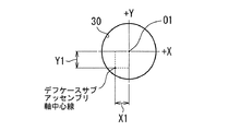
また、図5に示されるように、第1の測定ユニット26aは、支持部材13の軸線C1の回りの角度位相がエンコーダ29によって検出される。さらに、第1の測定ユニット26aには、一対の支持部材13,14の各コーン部13a,14aがデフケースサブアッセンブリ4の各軸部7,8の軸穴の開口端部に係合された状態で、測定子31がキャリア2のベアリング支持部11,12と同一軸線C2上に設けられるオイルシール装着部30に接触される振れセンサ32が設けられる。そして、本サイドシム選択装置18では、上記振れセンサ32の測定子31がオイルシール装着部30に接触された状態で、エンコーダ29によって支持部材13の角度位相が検出されつつ、デフケースサブアッセンブリ4が軸中心線の回りに回転されることにより、マイクロコンピュータで構成される演算装置によって、上記エンコーダ29の検出データと振れセンサ32の検出データとが演算処理されて、図7に示されるように、キャリア2のオイルシール装着部30の中心O1に対するデフケースサブアッセンブリ4の軸中心線の、X方向(図4に示される紙面視左右方向)への偏心量X1とY方向(図4に示される紙面視上下方向)への偏心量Y1とが導出される。   Further, as shown in FIG. 5, in the first measurement unit 26 a, the encoder 29 detects the angular phase around the axis C <b> 1 of the support member 13. Further, in the first measurement unit 26a, the cone portions 13a, 14a of the pair of support members 13, 14 are engaged with the opening end portions of the shaft holes of the shaft portions 7, 8 of the differential case subassembly 4. Thus, a vibration sensor 32 is provided in which the probe 31 is brought into contact with an oil seal mounting portion 30 provided on the same axis C2 as the bearing support portions 11 and 12 of the carrier 2. In the side shim selection device 18, the differential case subassembly 4 is pivoted while the encoder 29 detects the angular phase of the support member 13 while the probe 31 of the shake sensor 32 is in contact with the oil seal mounting portion 30. By rotating around the center line, the detection data of the encoder 29 and the detection data of the shake sensor 32 are calculated by an arithmetic unit constituted by a microcomputer, and as shown in FIG. Eccentric amount X1 in the X direction (left and right direction as viewed in FIG. 4) of the axial center line of the differential case subassembly 4 with respect to the center O1 of the oil seal mounting portion 30 and Y direction (as viewed in FIG. 4). Eccentric amount Y1 in the vertical direction) is derived.

また、図5に示されるように、第1の測定ユニット26aには、一対の支持部材13,14の各コーン部13a,14aがデフケースサブアッセンブリ4の各軸部7,8の軸穴の開口端部に係合された状態で、本体フレーム19に位置決め固定されたキャリア2のオイルシール装着部30の開口端面が必要に応じて押圧される第1の押圧ヘッド33が設けられる。そして、本サイドシム選択装置18では、上記押圧ヘッド33によってキャリア2のオイルシール装着部30の開口端面が押圧されることにより、デフケースサブアッセンブリ4に図5における紙面視右方向への推進力が作用される。これにより、ユニットベース22が本体フレーム19に対して図5における紙面視右方向へスライド移動されて、デフケースサブアッセンブリ4がキャリア2に対して図5における紙面視右方向へ移動されることにより、第1のサイドベアリング9のアウタレース外側面に所定のベアリング与圧が付与される構造になっている。   Further, as shown in FIG. 5, the first measurement unit 26 a includes a cone portion 13 a, 14 a of the pair of support members 13, 14 that has an opening in the shaft hole of each shaft portion 7, 8 of the differential case subassembly 4. A first pressing head 33 is provided to press the opening end surface of the oil seal mounting portion 30 of the carrier 2 positioned and fixed to the main body frame 19 as necessary, while being engaged with the end portion. In the side shim selection device 18, when the opening end surface of the oil seal mounting portion 30 of the carrier 2 is pressed by the pressing head 33, a propulsive force in the right direction as viewed in FIG. 5 acts on the differential case subassembly 4. Is done. As a result, the unit base 22 is slid in the right direction as viewed in FIG. 5 with respect to the main body frame 19, and the differential case subassembly 4 is moved in the right direction as viewed in FIG. 5 with respect to the carrier 2. A predetermined bearing pressure is applied to the outer race outer surface of the first side bearing 9.

なお、本サイドシム選択装置18は、上記ベアリング与圧が、ユニットベース22に設けられる流体圧シリンダ34の推進力が調節されて任意に設定される。また、本サイドシム選択装置18では、キャリア2の各ベアリング支持部11,12に各マスタシム15,16が組み付けられていない場合には、押圧ヘッド33によってデフケースサブアッセンブリ4に図5における紙面視右方向への推進力が作用されて、ユニットベース22が本体フレーム19に対して図5における紙面視右方向へスライド移動されることにより、ドライブピニオンギヤ3とリングギヤ6とがノンバックの状態になるように構成される。図5に示されるように、第2の測定ユニット26bには、外円錐面を有するコーン部14aが先端に形成された支持部材14が軸線C1の回りに回転可能に設けられる。該支持部材14は、図2に示されるエンコーダ35によって軸線C1の回りの角度位相が検出される。また、第2の測定ユニット26bには、一対の支持部材13,14の各コーン部13a,14aがデフケースサブアッセンブリ4の各軸部7,8の軸穴の開口端部に係合された状態で、キャリア2のベアリング支持部11,12と同一軸線C2上に設けられるオイルシール装着部36に測定子37が接触される振れセンサ38が設けられる。   In the side shim selection device 18, the bearing pressure is arbitrarily set by adjusting the driving force of the fluid pressure cylinder 34 provided in the unit base 22. Further, in the side shim selection device 18, when the master shims 15 and 16 are not assembled to the bearing support portions 11 and 12 of the carrier 2, the pressing head 33 causes the differential case subassembly 4 to be placed in the right direction in FIG. When the unit base 22 is slid in the right direction in FIG. 5 with respect to the main body frame 19, the drive pinion gear 3 and the ring gear 6 are brought into a non-back state. Composed. As shown in FIG. 5, the second measurement unit 26b is provided with a support member 14 having a cone portion 14a having an outer conical surface formed at the tip thereof so as to be rotatable around an axis C1. The support member 14 is detected by the encoder 35 shown in FIG. 2 in the angular phase around the axis C1. In the second measurement unit 26b, the cone portions 13a, 14a of the pair of support members 13, 14 are engaged with the open end portions of the shaft holes of the shaft portions 7, 8 of the differential case subassembly 4. Thus, a shake sensor 38 is provided in which a probe 37 is brought into contact with an oil seal mounting portion 36 provided on the same axis C2 as the bearing support portions 11 and 12 of the carrier 2.

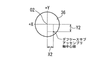
そして、本サイドシム選択装置18では、上記振れセンサ38の測定子37がオイルシール装着部36に接触された状態で、図2に示されるエンコーダ35によって支持部材14の角度位相が検出されつつ、デフケースサブアッセンブリ4が軸中心線の回りに回転されることにより、マイクロコンピュータで構成される演算装置によって、上記エンコーダ35の検出データと振れセンサ38の検出データとが演算処理されて、図8に示されるように、キャリア2のオイルシール装着部36の中心O2に対するデフケースサブアッセンブリ4の軸中心線の、X方向(図4に示される紙面視左右方向)への偏心量X2とY方向(図4に示される紙面視上下方向)への偏心量Y2とが導出される。また、図5に示されるように、第2の測定ユニット26bには、一対の支持部材13,14の各コーン部13a,14aがデフケースサブアッセンブリ4の各軸部7,8の軸穴の開口端部に係合された状態で、本体フレーム19に位置決め固定されたキャリア2のオイルシール装着部36の開口端面が必要に応じて押圧される第2の押圧ヘッド39が設けられる。   In the side shim selection device 18, the differential phase of the support member 14 is detected by the encoder 35 shown in FIG. 2 while the probe 37 of the shake sensor 38 is in contact with the oil seal mounting portion 36. When the subassembly 4 is rotated around the axis center line, the detection data of the encoder 35 and the detection data of the shake sensor 38 are calculated by an arithmetic unit constituted by a microcomputer, and is shown in FIG. As shown in FIG. 4, the eccentric amount X2 and the Y direction (FIG. 4) of the axial center line of the differential case subassembly 4 with respect to the center O2 of the oil seal mounting portion 36 of the carrier 2 Eccentric amount Y2 in the vertical direction as viewed in FIG. Further, as shown in FIG. 5, the second measurement unit 26 b includes the cone portions 13 a and 14 a of the pair of support members 13 and 14, and the shaft holes of the shaft portions 7 and 8 of the differential case subassembly 4. A second pressing head 39 is provided to press the opening end surface of the oil seal mounting portion 36 of the carrier 2 positioned and fixed to the main body frame 19 as necessary, while being engaged with the end portion.

そして、本サイドシム選択装置18では、上記押圧ヘッド39によってキャリア2のオイルシール装着部36の開口端面が押圧されて、デフケースサブアッセンブリ4に図5における紙面視左方向への推進力が作用される。これにより、ユニットベース22が本体フレーム19に対して図5における紙面視左方向へスライド移動されて、デフケースサブアッセンブリ4がキャリア2に対して図5における紙面視左方向へ移動されることにより、第2のサイドベアリング10のアウタレース外側面に所定のベアリング与圧が付与される。なお、該ベアリング与圧は、ユニットベース22に設けられる流体圧シリンダ40(図2参照)の推進力が調節されて任意に設定される。また、図5に示されるように、本サイドシム選択装置18は、本体フレーム19に設けられる駆動装置43(駆動手段)によって、当該サイドシム選択装置18の正規位置に位置決めされたディファレンシャルキャリアアッセンブリ1のドライブピニオンシャフト17が回転駆動される。   In the side shim selection device 18, the opening end surface of the oil seal mounting portion 36 of the carrier 2 is pressed by the pressing head 39, and the driving force in the leftward direction in FIG. 5 acts on the differential case subassembly 4. . As a result, the unit base 22 is slid in the left direction in FIG. 5 with respect to the main body frame 19, and the differential case subassembly 4 is moved in the left direction in FIG. 5 with respect to the carrier 2. A predetermined bearing pressure is applied to the outer race outer surface of the second side bearing 10. The bearing pressure is arbitrarily set by adjusting the driving force of the fluid pressure cylinder 40 (see FIG. 2) provided in the unit base 22. Further, as shown in FIG. 5, the present side shim selection device 18 is configured to drive the differential carrier assembly 1 that is positioned at a normal position of the side shim selection device 18 by a drive device 43 (drive means) provided in the main body frame 19. The pinion shaft 17 is rotationally driven.

上記駆動装置43は、回転軸44の上端部に回転台45が設けられて、該回転台45に立設されるピン46が、上記ドライブピニオンシャフト17の下部に固着されたフランジ47に係合される。なお、図2及び図5に示されるように、本サイドシム選択装置18には、2つの駆動装置43が並設されており、各駆動装置43がディファレンシャルキャリアアッセンブリ1に応じて使い分けされる。図5に示されるように、本サイドシム選択装置18は、本体フレーム19の所定位置に変位検出センサ41が設けられる。そして、本サイドシム選択装置18は、上記駆動装置43によってドライブピニオンシャフト17が回転駆動されてドライブピニオンギヤ3が回転されることにより、デフケースサブアッセンブリ4が軸中心線(支持部材13,14の軸線C1)の回りに回転されて、変位検出センサ41によって、この時の上記ユニットベース22に設けられる被検出子42の位置が検出されることにより、デフケースサブアッセンブリ4の、キャリア2に対する軸中心線方向(図5における紙面視左右方向)への各変位L1,L2,L3が測定される。   In the drive device 43, a rotary base 45 is provided at the upper end of the rotary shaft 44, and a pin 46 erected on the rotary base 45 is engaged with a flange 47 fixed to the lower part of the drive pinion shaft 17. Is done. As shown in FIGS. 2 and 5, the side shim selection device 18 has two drive devices 43 arranged in parallel, and each drive device 43 is selectively used in accordance with the differential carrier assembly 1. As shown in FIG. 5, the side shim selection device 18 is provided with a displacement detection sensor 41 at a predetermined position of the main body frame 19. In the side shim selection device 18, the drive pinion shaft 17 is rotationally driven by the drive device 43 and the drive pinion gear 3 is rotated, so that the differential case subassembly 4 is rotated along the axis center line (the axis C 1 of the support members 13 and 14. ) And the position of the detection element 42 provided on the unit base 22 at this time is detected by the displacement detection sensor 41, so that the differential case subassembly 4 is in the axial center line direction with respect to the carrier 2 Each displacement L1, L2, L3 in the left-right direction in FIG. 5 is measured.

そして、本サイドシム選択装置18は、上記演算装置によって、各変位L1,L2,L3、並びに各偏心量X1,Y1,X2,Y2が、サイドシム選択式に基づいて演算処理されて各サイドシムの厚さT1,T2が導出されるように構成される。
なお、上記サイドシム選択式は、
T1=L3−L1+M1+k×(BL0+A)+補正値1(以下、第1の選択式と称す。)
T2=L2−L1+M1+M2−T1+補正値2(以下、第2の選択式と称す。)
で表される。ここで、M1は、反フランジ側のベアリング支持部11(第1のベアリング支持部11)に組み付けられる第1のマスタシム15の厚さ、M2は、フランジ側のベアリング支持部12(第2のベアリング支持部12)に組み付けられる第2のマスタシム16の厚さ、kは、ディファレンシャルキャリアアッセンブリ1におけるドライブピニオンギヤ3とリングギヤ6とのバックラッシュとデフケースサブアッセンブリ4の軸中心線(支持部材13,14の軸線C1)方向への移動量とに応じて設定される設計上の係数、BL0は、バックラッシュねらい値である。
The side shim selection device 18 calculates the displacements L1, L2, and L3 and the eccentric amounts X1, Y1, X2, and Y2 based on the side shim selection formula by the arithmetic device, and calculates the thickness of each side shim. T1 and T2 are derived.
The side shim selection formula is
T1 = L3−L1 + M1 + k × (BL0 + A) + correction value 1 (hereinafter referred to as a first selection formula)
T2 = L2-L1 + M1 + M2-T1 + correction value 2 (hereinafter referred to as a second selection formula)
It is represented by Here, M1 is the thickness of the first master shim 15 assembled to the bearing support 11 on the non-flange side (first bearing support 11), and M2 is the bearing support 12 on the flange side (second bearing). The thickness, k, of the second master shim 16 assembled to the support portion 12) is determined by the backlash between the drive pinion gear 3 and the ring gear 6 in the differential carrier assembly 1 and the axial center line of the differential case subassembly 4 (the support members 13, 14). A design coefficient BL0 set according to the amount of movement in the direction of the axis C1), BL0, is a target value for backlash.

また、上記Aは、キャリア2のベアリング支持部11,12の軸線C2に対するデフケースサブアッセンブリ4の軸中心線の偏心量の補正値である。該補正値Aは、図1に示されるように、ドライブピニオンギヤ3とリングギヤ5との歯当りねらい位置Sを基準とした時の、各サイドシム組み付け端面までのデフケースサブアッセンブリ4の軸中心線方向の距離の割合をa:b(ここで、a+b=1)として、さらに、ディファレンシャルキャリアアッセンブリ1における、デフケースサブアッセンブリ4の上下方向(図1における紙面視方向)への単位変位量に対するドライブピニオンギヤ3とリングギヤ6とのバックラッシュの変化量に応じて設定される設計上の係数をm、並びにディファレンシャルキャリアアッセンブリ1における、デフケースサブアッセンブリ4の前後方向(図1における紙面視上下方向)への単位変位量に対するドライブピニオンギヤ3とリングギヤ6とのバックラッシュの変化量に応じて設定される設計上の係数をnとする場合、
A=m(a・X1+b・X2)+n(a・Y1+b・Y2)で表される。
A is a correction value for the amount of eccentricity of the center line of the differential case subassembly 4 with respect to the axis C2 of the bearing support portions 11 and 12 of the carrier 2. As shown in FIG. 1, the correction value A is determined in the axial center line direction of the differential case subassembly 4 up to the side shim assembly end faces when the tooth contact aiming position S between the drive pinion gear 3 and the ring gear 5 is used as a reference. The ratio of distance is a: b (where a + b = 1), and the drive pinion gear 3 with respect to the unit displacement amount in the differential carrier subassembly 4 in the vertical direction of the differential case subassembly 4 (viewed in the drawing in FIG. 1) The design coefficient set according to the amount of change in the backlash with the ring gear 6 is m, and the unit displacement in the differential carrier subassembly 1 in the front-rear direction of the differential case subassembly 4 (vertical direction in the drawing in FIG. 1). The drive pinion gear 3 and the ring gear 6 If the coefficients of the design which is set according to the amount of change in rush and n,
A = m (a * X1 + b * X2) + n (a * Y1 + b * Y2).

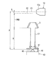
図6に示されるように、本サイドシム選択装置18は、上記駆動装置43に、当該駆動装置43の軸中心線に対して同一軸線上に配置される尖端部材48が設けられる。そして、本サイドシム選択装置18は、尖端部材48が、正規位置に位置決め固定されたディファレンシャルキャリアアッセンブリ1の一端にドライブピニオンギヤ3が取り付けられたドライブピニオンシャフト17の他端の端面に当接されることにより、該ドライブピニオンシャフト17の他端の端面とデフケースサブアッセンブリ4の軸中心線(支持部材13,14の軸線C1)との距離Pが測定される(第2の測定手段)構造になっている。また、本サイドシム選択装置18は、上記演算装置に、キャリア2のベアリング支持部11,12の軸線C2に対する、デフケースサブアッセンブリ4の軸中心線(支持部材13,14の軸線)のオフセット値Q(測定値)、及びドライブピニオンギヤ3の取付基準位置(PMD基準)とドライブピニオンシャフト17の他端の端面との距離R(前工程での測定結果)が設定されて、P,Q,Rが演算装置によって演算処理されることにより、ドライブピニオンギヤ3の取付基準位置とキャリア2のベアリング支持部11,12の軸線C2との間の距離PMD(Pinion Mount Distance)が導出される。 As shown in FIG. 6, in the side shim selection device 18, the driving device 43 is provided with a pointed member 48 disposed on the same axis with respect to the axial center line of the driving device 43. In the side shim selection device 18, the pointed member 48 is brought into contact with the end surface of the other end of the drive pinion shaft 17 in which the drive pinion gear 3 is attached to one end of the differential carrier assembly 1 that is positioned and fixed at a normal position. Thus, the distance P between the end surface of the other end of the drive pinion shaft 17 and the axial center line of the differential case subassembly 4 (the axis C1 of the support members 13 and 14) is measured (second measuring means). Yes. Further, the side shim selection device 18 sends an offset value Q (the axial center line of the differential case subassembly 4 (the axis of the support members 13 and 14) with respect to the axis C2 of the bearing support portions 11 and 12 of the carrier 2 to the arithmetic device. Measurement value) and the distance R (measurement result in the previous process ) between the mounting reference position of the drive pinion gear 3 (PMD reference) and the other end face of the drive pinion shaft 17 are set, and P, Q, and R are calculated. By performing arithmetic processing by the apparatus, a distance PMD (Pinion Mount Distance) between the reference mounting position of the drive pinion gear 3 and the axis C2 of the bearing support portions 11 and 12 of the carrier 2 is derived.

以下、本実施の形態の作用を説明する。まず、キャリア2の各ベアリング支持部11,12(軸支部)に各マスタシム15,16が組み付けられたディファレンシャルキャリアアッセンブリ1が、パレット(ディファレンシャルキャリアアッセンブリ搬送用治具)に取り付けられる。そして、該ディファレンシャルキャリアアッセンブリ1が取り付けられたパレットは、搬送装置によって搬送されて、サイドシム選択装置18の所定位置に位置決めされる。上記パレットが位置決めされると、サイドシム選択装置18の押圧部材21が下降されて、ディファレンシャルキャリアアッセンブリ1のキャリア2がサイドシム選択装置18における正規位置に位置決め固定される。次に、図5に示されるように、サイドシム選択装置18の一対の支持部材13,14(センタリングコーン)が、デフケースサブアッセンブリ4の両端の軸部7,8の各軸穴に係合されて、各軸部7,8の軸穴の開口端部が、各支持部材13,14の各コーン部13a,14aによって押圧される。   Hereinafter, the operation of the present embodiment will be described. First, the differential carrier assembly 1 in which the master shims 15 and 16 are assembled to the bearing support portions 11 and 12 (shaft support portions) of the carrier 2 is attached to a pallet (differential carrier assembly transport jig). Then, the pallet to which the differential carrier assembly 1 is attached is transported by the transport device and positioned at a predetermined position of the side shim selection device 18. When the pallet is positioned, the pressing member 21 of the side shim selection device 18 is lowered, and the carrier 2 of the differential carrier assembly 1 is positioned and fixed at a normal position in the side shim selection device 18. Next, as shown in FIG. 5, the pair of support members 13 and 14 (centering cones) of the side shim selection device 18 are engaged with the shaft holes of the shaft portions 7 and 8 at both ends of the differential case subassembly 4. The open end portions of the shaft holes of the shaft portions 7 and 8 are pressed by the cone portions 13a and 14a of the support members 13 and 14, respectively.

これにより、デフケースサブアッセンブリ4の軸中心線が一対の支持部材13,14の軸線C1に対して同一軸線上に配置されて、当該デフケースサブアッセンブリ4が芯出しされる。なお、デフケースサブアッセンブリ4が芯出しされた状態では、当該デフケースサブアッセンブリ4の軸中心線が、キャリア2のベアリング支持部11,12の軸線C2(図6参照)に対して、上方(図1における紙面視上方)へ所定距離(本実施の形態では1mm)だけオフセットされる。次に、図6に示されるように、サイドシム選択装置18の駆動装置43の回転台45が上昇されて、該回転台45のピン46がディファレンシャルキャリアアッセンブリ1のドライブピニオンシャフト17に固定されたフランジ47に係合されると共に、尖端部材48が一端にドライブピニオンギヤ3が取り付けられたドライブピニオンシャフト17の他端の端面に当接される。この状態で、ドライブピニオンシャフト17の他端の端面とデフケースサブアッセンブリ4の軸中心線(支持部材13,14の軸線C1)との距離Pが測定されて、該測定結果が演算装置に設定される。 As a result, the axial center line of the differential case subassembly 4 is arranged on the same axis with respect to the axial line C1 of the pair of support members 13 and 14, and the differential case subassembly 4 is centered. When the differential case subassembly 4 is centered, the axial center line of the differential case subassembly 4 is above the axis C2 (see FIG. 6) of the bearing support portions 11 and 12 of the carrier 2 (see FIG. 1). Is offset by a predetermined distance (up to 1 mm in the present embodiment). Next, as shown in FIG. 6, the turntable 45 of the drive device 43 of the side shim selection device 18 is raised, and the pin 46 of the turntable 45 is fixed to the drive pinion shaft 17 of the differential carrier assembly 1. 47, and the pointed member 48 is brought into contact with the other end face of the drive pinion shaft 17 to which the drive pinion gear 3 is attached at one end . In this state, the distance P between the end face of the other end of the drive pinion shaft 17 and the axial center line of the differential case subassembly 4 (axis C1 of the support members 13 and 14) is measured, and the measurement result is set in the arithmetic unit. The

また、上記距離P、並びに、キャリア2のベアリング支持部11,12の軸線C2に対する、デフケースサブアッセンブリ4の軸中心線(支持部材13,14の軸線)のオフセット値Q及びドライブピニオンギヤ3の取付基準位置(PMD基準)とドライブピニオンシャフト17の他端の端面との距離Rが、当該演算装置によって演算処理されてドライブピニオンギヤ3の取付基準位置とキャリア2のベアリング支持部11,12の軸線C2との間の距離PMD(Pinion Mount Distance)が導出される。そして、導出されたPMDが上下限管理されることにより、ドライブピニオンギヤ3とリングギヤ6との歯当り確認が行われる。一方、デフケースサブアッセンブリ4が一対の支持部材13,14によって支持された状態で、押圧ヘッド33によってキャリア2のオイルシール装着部30の開口端面が押圧されて、第1のサイドベアリング9のアウタレース外側面に0.5kNのベアリング与圧が付与される。この状態で、駆動装置43によってドライブピニオンギヤ3(ドライブピニオンシャフト17)が所定時間だけ回転駆動されて、ディファレンシャルキャリアアッセンブリ1の各部が調和される。 Further, the distance P, the offset value Q of the axis center line of the differential case subassembly 4 (the axis of the support members 13 and 14) with respect to the axis C2 of the bearing support portions 11 and 12 of the carrier 2, and the mounting reference of the drive pinion gear 3 The distance R between the position (PMD reference) and the other end face of the drive pinion shaft 17 is processed by the calculation device, and the reference mounting position of the drive pinion gear 3 and the axis C2 of the bearing support portions 11 and 12 of the carrier 2 A distance PMD (Pinion Mount Distance) is derived. The derived PMD is subjected to upper and lower limit management, so that the tooth contact between the drive pinion gear 3 and the ring gear 6 is confirmed. On the other hand, with the differential case subassembly 4 supported by the pair of support members 13, 14, the opening end surface of the oil seal mounting portion 30 of the carrier 2 is pressed by the pressing head 33, and the outer side of the first side bearing 9 is outside the outer race. A bearing pressure of 0.5 kN is applied to the side surface. In this state, the drive pinion gear 3 (drive pinion shaft 17) is rotationally driven by the drive device 43 for a predetermined time, and the various parts of the differential carrier assembly 1 are harmonized.

そして、ディファレンシャルキャリアアッセンブリ1が調和された後、第1のサイドベアリング9のアウタレース外側面にベアリング与圧が保持された状態で、デフケースサブアッセンブリ4の変位L1が測定される。次に、第1のサイドベアリング9のアウタレース外側面のベアリング与圧が開放された後、押圧ヘッド39によってキャリア2のオイルシール装着部36の開口端面が押圧されて、第2のサイドベアリング10のアウタレース外側面に0.5kNのベアリング与圧が付与される。この状態で、駆動装置43によってドライブピニオンギヤ3(ドライブピニオンシャフト17)が所定時間だけ回転駆動されて、ディファレンシャルキャリアアッセンブリ1の各部が調和される。そして、ディファレンシャルキャリアアッセンブリ1が調和された後、第2のサイドベアリング10のアウタレース外側面にベアリング与圧が保持された状態で、デフケースサブアッセンブリ4の変位L2が測定される。   Then, after the differential carrier assembly 1 is harmonized, the displacement L1 of the differential case subassembly 4 is measured in a state where the bearing pressure is held on the outer race outer surface of the first side bearing 9. Next, after the bearing pressure on the outer race outer surface of the first side bearing 9 is released, the opening end surface of the oil seal mounting portion 36 of the carrier 2 is pressed by the pressing head 39, so that the second side bearing 10 A bearing pressure of 0.5 kN is applied to the outer surface of the outer race. In this state, the drive pinion gear 3 (drive pinion shaft 17) is rotationally driven by the drive device 43 for a predetermined time, and the various parts of the differential carrier assembly 1 are harmonized. Then, after the differential carrier assembly 1 is harmonized, the displacement L2 of the differential case subassembly 4 is measured in a state where the bearing pressure is held on the outer race outer surface of the second side bearing 10.

また、各変位L1,L2が測定された後、キャリア2の各ベアリング支持部11,12の各マスタシム15,16が取り外される。次に、押圧ヘッド33によってキャリア2のオイルシール装着部30の開口端面が0.5kNの推進力で押圧されることにより、デフケースサブアッセンブリ4がキャリア2に対して軸中心線方向反フランジ側(図1における紙面視右方向)へ移動されてドライブピニオンギヤ3とリングギヤ6とがノンバックの状態になる。この状態で、駆動装置43によってドライブピニオンギヤ3(ドライブピニオンシャフト17)が所定時間だけ回転駆動されて、ディファレンシャルキャリアアッセンブリ1の各部が調和される。そして、ディファレンシャルキャリアアッセンブリ1が調和された後、ドライブピニオンギヤ3とリングギヤ4とがノンバックの状態で、デフケースサブアッセンブリ4の変位L3が測定される。次に、デフケースサブアッセンブリ4が一対の支持部材13,14によって支持されて、且つ各サイドベアリングのベアリング与圧が開放された状態で、キャリア2の各オイルシール装着部30,36の中心O1,O2が測定される。   Further, after the displacements L1 and L2 are measured, the master shims 15 and 16 of the bearing support portions 11 and 12 of the carrier 2 are removed. Next, when the opening end surface of the oil seal mounting portion 30 of the carrier 2 is pressed by the pressing head 33 with a driving force of 0.5 kN, the differential case subassembly 4 is against the carrier 2 in the axial center line direction opposite flange side ( 1), the drive pinion gear 3 and the ring gear 6 are brought into a non-back state. In this state, the drive pinion gear 3 (drive pinion shaft 17) is rotationally driven by the drive device 43 for a predetermined time, and the various parts of the differential carrier assembly 1 are harmonized. After the differential carrier assembly 1 is harmonized, the displacement L3 of the differential case subassembly 4 is measured with the drive pinion gear 3 and the ring gear 4 being non-back. Next, in a state where the differential case subassembly 4 is supported by the pair of support members 13 and 14 and the bearing pressure of each side bearing is released, the center O1 of each oil seal mounting portion 30 and 36 of the carrier 2 is set. O2 is measured.

そして、各オイルシール装着部30,36の中心O1,O2、並びに、一対の支持部材13,14の軸線位置から得られるデフケースサブアッセンブリ4の軸中心線の位置に基づいて、演算装置によって、中心O1に対するデフケースサブアッセンブリ4の軸中心線のX方向への偏心量X1とY方向への偏心量Y1とが導出されると共に、中心O2に対するデフケースサブアッセンブリ4の軸中心線のX方向への偏心量X2とY方向への偏心量Y2とが導出される。さらに、第1の選択式によって第1のサイドシムの厚さT1が導出されると共に、第2の選択式によって第2のサイドシムの厚さT2が導出される。   Based on the center O1, O2 of each oil seal mounting portion 30, 36 and the position of the axial center line of the differential case subassembly 4 obtained from the axial position of the pair of support members 13, 14, the arithmetic unit performs the center operation. An eccentricity amount X1 of the axial center line of the differential case subassembly 4 with respect to O1 in the X direction and an eccentricity amount Y1 of the axial direction of the differential case subassembly 4 with respect to the center O2 are derived. An amount X2 and an eccentric amount Y2 in the Y direction are derived. Further, the first side shim thickness T1 is derived by the first selection formula, and the second side shim thickness T2 is derived by the second selection formula.

本実施の形態では以下の効果を奏する。
本サイドシム選択方法及びサイドシム選択装置18では、デフケースサブアッセンブリ4の両端の軸部7,8の各軸穴の開口端部が、一対の支持部材13,14(センタリングコーン)のコーン部13a,14aによって押圧される。
したがって、本サイドシム選択方法及びサイドシム選択装置18では、デフケースサブアッセンブリ4の軸中心線が一対の支持部材13,14の軸線C1に一致されて、当該デフケースサブアッセンブリ4が芯出しされる。これにより、従来のサイドシム選択装置のように、デフケースサブアッセンブリ4の軸中心線の位置が、キャリア2並びに一対の支持部材13,14に対してばらつくことがなく、デフケースサブアッセンブリ4の軸中心線の位置が安定するため、各変位L1,L2,L3の繰り返しの測定精度が高められて適正な厚さT1,T2のサイドシムが選択される。
This embodiment has the following effects.
In the present side shim selection method and side shim selection device 18, the opening end portions of the shaft holes of the shaft portions 7 and 8 at both ends of the differential case subassembly 4 are the cone portions 13 a and 14 a of the pair of support members 13 and 14 (centering cone). Is pressed by.
Therefore, in the side shim selection method and the side shim selection device 18, the axial center line of the differential case subassembly 4 is aligned with the axial line C1 of the pair of support members 13 and 14, and the differential case subassembly 4 is centered. Thus, unlike the conventional side shim selection device, the position of the axial center line of the differential case subassembly 4 does not vary with respect to the carrier 2 and the pair of support members 13 and 14, and the axial center line of the differential case subassembly 4 Therefore, the measurement accuracy of the repetition of each of the displacements L1, L2, and L3 is increased, and a side shim having an appropriate thickness T1 and T2 is selected.

また、本サイドシム選択方法及びサイドシム選択装置18では、デフケースサブアッセンブリ4の軸中心線の位置が正確に検知されるため、キャリア2のベアリング支持部11,12の軸線C2(本実施の形態では、オイルシール装着部30,36の中心O1,O2が測定されてC2の位置が検知される。)に対するデフケースサブアッセンブリ4の軸中心線(本実施の形態では、支持部材13,14の軸線位置C1の位置が検知される。)の各偏心量X1,Y1,X2,Y2が高い精度で導出されるため、これら各偏心量X1,Y1,X2,Y2に基づいてより適正な厚さT1,T2のサイドシムが選択される。   Further, in the side shim selection method and the side shim selection device 18, since the position of the axial center line of the differential case subassembly 4 is accurately detected, the axial line C2 of the bearing support portions 11 and 12 of the carrier 2 (in this embodiment, The axial center line C1 of the differential case subassembly 4 with respect to the center O1 and O2 of the oil seal mounting portions 30 and 36 is measured and the position of C2 is detected (in this embodiment, the axial position C1 of the support members 13 and 14). ) Is derived with high accuracy, so that more appropriate thicknesses T1, T2 are obtained based on these eccentric amounts X1, Y1, X2, Y2. Side shims are selected.

さらに、本サイドシム選択方法及びサイドシム選択装置18では、デフケースサブアッセンブリ4の軸中心線の位置が正確に検知されるため、尖端部材48が一端にドライブピニオンギヤ3が取り付けられたドライブピニオンシャフト17の他端の端面に当接されてドライブピニオンシャフト17の他端の端面とデフケースサブアッセンブリ4の軸中心線(支持部材13,14の軸線C1)との距離Pが高い精度で測定される。これにより、距離Pに基づいて、ドライブピニオンギヤ3の取付基準位置(PMD基準)とキャリア2のベアリング支持部11,12の軸線C2との間の距離PMD(Pinion Mount Distance)が導出される。したがって、導出されたPMDが上下限管理されることによりドライブピニオンギヤ3とリングギヤ6との歯当り確認を行うことが可能になる。これにより、従来、熟練作業者による目視での歯当り確認工程が廃止されて、歯当り基準が明確化されて品質(信頼性)が高められると共に、定量検査で済ませることが可能になり、生産性を向上させることができる。 Further, in the present side shim selection method and side shim selection device 18, since the position of the axial center line of the differential case subassembly 4 is accurately detected, the pointed member 48 is connected to the drive pinion shaft 17 to which the drive pinion gear 3 is attached at one end. held in contact with an end surface of the end by a distance P between the other end of the end face and the axial center line of the differential case subassembly 4 of the drive pinion shaft 17 (axis C1 of the support members 13, 14) is measured with high accuracy. Thereby, based on the distance P, a distance PMD (Pinion Mount Distance) between the mounting reference position (PMD reference) of the drive pinion gear 3 and the axis C2 of the bearing support portions 11 and 12 of the carrier 2 is derived. Therefore, it is possible to check the contact between the drive pinion gear 3 and the ring gear 6 by managing the upper and lower limits of the derived PMD. This eliminates the conventional tooth contact confirmation process by skilled workers, clarifying the tooth contact standard, improving quality (reliability), and enabling quantitative inspection to be completed. Can be improved.

なお、本サイドシム選択方法及びサイドシム選択装置18は、ディファレンシャルキャリアアッセンブリ1と同様に、ハイポイドギヤのバックラッシュを適正に管理する必要があるトランスファアッセンブリ等に採用することが可能である。   The side shim selection method and the side shim selection device 18 can be employed in a transfer assembly or the like that needs to properly manage the backlash of the hypoid gear, like the differential carrier assembly 1.

本ディファレンシャルキャリアアッセンブリのサイドシム選択装置の説明図で、特に、デフケースサブアッセンブリの支持構造の概略を示す図である。It is explanatory drawing of the side shim selection apparatus of this differential carrier assembly, and is a figure which shows the outline of the support structure of a differential case subassembly especially. 本ディファレンシャルキャリアアッセンブリのサイドシム選択装置の前面図である。It is a front view of the side shim selection apparatus of this differential carrier assembly. 本ディファレンシャルキャリアアッセンブリのサイドシム選択装置の上面図である。It is a top view of the side shim selection apparatus of this differential carrier assembly. 本ディファレンシャルキャリアアッセンブリのサイドシム選択装置の側面図である。It is a side view of the side shim selection apparatus of this differential carrier assembly. 本ディファレンシャルキャリアアッセンブリのサイドシム選択装置の説明図で、特に、測定ユニットの構造の概略を示す図である。It is explanatory drawing of the side shim selection apparatus of this differential carrier assembly, and is a figure which shows the outline of the structure of a measurement unit especially. 本ディファレンシャルキャリアアッセンブリのサイドシム選択装置の説明図で、特に、PMDが測定される構造を示す図である。It is explanatory drawing of the side shim selection apparatus of this differential carrier assembly, and is a figure which shows the structure where PMD is measured especially. 本ディファレンシャルキャリアアッセンブリのサイドシム選択装置の説明図で、特に、キャリアの反フランジ側のオイルシール装着部の中心O1に対する、デフケースサブアッセンブリの軸中心線の偏心量を示す図である。It is explanatory drawing of the side shim selection apparatus of this differential carrier assembly, and is a figure which shows the eccentric amount of the axial centerline of a differential case subassembly with respect to the center O1 of the oil seal mounting part by the side of a carrier opposite flange. 本ディファレンシャルキャリアアッセンブリのサイドシム選択装置の説明図で、特に、キャリアのフランジ側のオイルシール装着部の中心O2に対する、デフケースサブアッセンブリの軸中心線の偏心量を示す図である。It is explanatory drawing of the side shim selection apparatus of this differential carrier assembly, and is a figure which shows the amount of eccentricity of the axial centerline of a differential case subassembly with respect to the center O2 of the oil seal mounting part by the side of a carrier flange especially.

符号の説明Explanation of symbols

1 ディファレンシャルキャリアアッセンブリ、2 キャリア、3 ドライブピニオンギヤ、4 デフケースサブアッセンブリ、5 フランジ、6 リングギヤ、7,8 軸部、9,10 サイドベアリング、11,12 ベアリング支持部(軸支部)、13,14 支持部材(センタリングコーン)、15,16 マスタシム、17 ドライブピニオンシャフト、18 サイドシム選択装置
1 differential carrier assembly, 2 carrier, 3 drive pinion gear, 4 differential case subassembly, 5 flange, 6 ring gear, 7, 8 shaft part, 9, 10 side bearing, 11, 12 bearing support part (shaft support part), 13, 14 support Member (Centering cone), 15, 16 Master shim, 17 Drive pinion shaft, 18 Side shim selection device

Claims (8)

ディファレンシャルキャリアアッセンブリの相互に噛み合わされるドライブピニオンギヤとリングギヤとのバックラッシュを調節するに際して、キャリアに配設されてデフケースサブアッセンブリの両端の軸部を支持する各軸支部のうち、該デフケースサブアッセンブリの反フランジ側の第1の軸部を支持する第1の軸支部に組み付けられる第1のサイドシムの厚さと、前記デフケースサブアッセンブリのフランジ側の第2の軸部を支持する第2の軸支部に組み付けられる第2のサイドシムの厚さと、が選択されるディファレンシャルキャリアアッセンブリのサイドシム選択方法であって、前記第1の軸支部に第1のマスタシムが組み付けられると共に前記第2の軸支部に第2のマスタシムが組み付けられるステップと、前記デフケースサブアッセンブリが芯出しされて軸中心線の回りに回転可能に支持されるステップと、前記第1の軸部に装着された第1のサイドベアリングのアウタレース外側面にスラスト方向のベアリング与圧を作用させつつ、前記ドライブピニオンギヤを回転駆動させた後、前記デフケースサブアッセンブリの、前記リングギヤの1回転当りの前記キャリアに対する軸中心線方向への変位の平均値L1が測定されるステップと、前記第2の軸部に装着された第2のサイドベアリングのアウタレース外側面にスラスト方向のベアリング与圧を作用させつつ、前記ドライブピニオンギヤを回転駆動させた後、前記デフケースサブアッセンブリの、前記リングギヤの1回転当りの前記キャリアに対する軸中心線方向への変位の平均値L2が測定されるステップと、前記第1の軸支部から前記第1のマスタシムが取り外されると共に前記第2の軸支部から前記第2のマスタシムが取り外されるステップと、各マスタシムが取り外された後、前記第1のサイドベアリングのアウタレース外側面にスラスト方向のベアリング与圧を作用させて、前記ドライブピニオンギヤと前記リングギヤとをノンバックにして、この状態で、前記ドライブピニオンギヤを回転駆動させて前記デフケースサブアッセンブリの、前記リングギヤの1回転当りの前記キャリアに対する軸中心線方向への変位の平均値L3が測定されるステップと、の各ステップを含んで構成されて、測定された各平均値L1,L2,L3に基づいて各サイドシムの厚さが選択されることを特徴とするディファレンシャルキャリアアッセンブリのサイドシム選択方法。 When adjusting the backlash between the drive pinion gear and the ring gear that are engaged with each other of the differential carrier assembly, the differential case subassembly of the differential case subassembly is disposed on the carrier and supports the shafts at both ends of the differential case subassembly. The thickness of the first side shim assembled to the first shaft supporting portion that supports the first shaft portion on the side opposite to the flange, and the second shaft supporting portion that supports the second shaft portion on the flange side of the differential case subassembly. A side shim selection method for a differential carrier assembly in which a thickness of a second side shim to be assembled is selected, wherein a first master shim is assembled to the first shaft support portion and a second shim is attached to the second shaft support portion. The step of assembling the master shim and the differential case sub A step in which the assembly is centered and supported so as to be rotatable around an axial center line; and a bearing pressure in a thrust direction is applied to an outer race outer surface of the first side bearing mounted on the first shaft portion. On the other hand, after the drive pinion gear is driven to rotate, an average value L1 of the displacement of the differential case subassembly in the axial center line direction with respect to the carrier per one rotation of the ring gear is measured; The drive pinion gear is driven to rotate while acting on the outer race outer surface of the second side bearing mounted on the shaft portion while thrust is applied, and then the differential case subassembly is rotated per rotation of the ring gear. Measuring an average value L2 of displacement in the axial center line direction with respect to the carrier; The step of removing the first master shim from the first shaft support and the second master shim from the second shaft support, and the outer race of the first side bearing after each master shim is removed on the outer surface by the action of the thrust direction of the bearing preload, said the drive pinion gear and said ring gear in the non-back, in this state, by rotating the said drive pinion gear, the differential case subassembly of the ring gear 1 A step of measuring an average value L3 of displacement in the axial center line direction with respect to the carrier per rotation, and each side shim based on the measured average values L1, L2, and L3. The side of the differential carrier assembly, characterized in that the thickness is selected Shim selection method. 相互に近接離反可能な一対のセンタリングコーンが前記デフケースサブアッセンブリの各軸部に形成された各軸穴に係合されることにより、前記デフケースサブアッセンブリが芯出しされて軸中心線の回りに回転可能に支持されることを特徴とする請求項1に記載のディファレンシャルキャリアアッセンブリのサイドシム選択方法。 A pair of centering cones that can move close to and away from each other are engaged with the respective shaft holes formed in the respective shaft portions of the differential case subassembly, whereby the differential case subassembly is centered and rotated around the shaft center line. The method for selecting a side shim of a differential carrier assembly according to claim 1, wherein the side shim is supported. 前記キャリアの各軸支部が各軸支部の半径方向へ2分割されて形成されて、前記一対のセンタリングコーンが前記デフケースサブアッセンブリの各軸部に形成された各軸穴に係合されることにより、前記デフケースサブアッセンブリが各軸支部の軸線に対して各軸支部の分割方向へ所定距離だけオフセットされることを特徴とする請求項1又は2に記載のディファレンシャルキャリアアッセンブリのサイドシム選択方法。 Each of the shaft support portions of the carrier is formed by being divided into two in the radial direction of each shaft support portion, and the pair of centering cones are engaged with each shaft hole formed in each shaft portion of the differential case subassembly. 3. The differential carrier assembly side shim selection method according to claim 1, wherein the differential case subassembly is offset by a predetermined distance with respect to the axis of each shaft support portion in the dividing direction of each shaft support portion. 前記デフケースサブアッセンブリが芯出しされた状態で、該デフケースサブアッセンブリの軸中心線と一端に前記ドライブピニオンギヤが取り付けられたドライブピニオンシャフトの他端の端面との距離が測定されて、該測定結果に基づいて前記ドライブピニオンギヤの取付基準位置と前記キャリアの各軸支部の軸線との間の距離が導出されて、前記ドライブピニオンギヤの前記取付基準位置と前記キャリアの各軸支部の軸線との間の距離に基づいて、前記ドライブピニオンギヤと前記リングギヤとの歯当りが評価されることを特徴とする請求項1〜3のいずれかに記載のサイドシム選択方法。 With the differential case subassembly centered, the distance between the axial center line of the differential case subassembly and the end surface of the other end of the drive pinion shaft with the drive pinion gear attached to one end is measured. A distance between the reference position of the drive pinion gear and the axis of each shaft support of the carrier is derived, and the distance between the reference position of the drive pinion gear and the axis of each support of the carrier The side shim selection method according to any one of claims 1 to 3, wherein a tooth contact between the drive pinion gear and the ring gear is evaluated based on the relationship. 請求項1〜4に記載のディファレンシャルキャリアアッセンブリのサイドシム選択方法に用いられるディファレンシャルキャリアアッセンブリのサイドシム選択装置であって、デフケースサブアッセンブリの両端の軸部を支持するキャリアの各軸支部に必要に応じて組み付けられるマスタシムと、前記デフケースサブアッセンブリが組み付けられた前記キャリアが正規位置に位置決め固定されるキャリア固定手段と、該キャリア固定手段により前記キャリアが位置決め固定された状態で、前記デフケースサブアッセンブリが芯出しされて軸中心線の回りに回転可能に支持される支持手段と、該支持手段によって支持された前記デフケースサブアッセンブリの両端の軸部に装着された一対のサイドベアリングにスラスト方向のベアリング与圧を作用させるベアリング与圧手段と、ドライブピニオンギヤが回転駆動されて該ドライブピニオンギヤに噛み合わされるリングギヤが回転される駆動手段と、前記デフケースサブアッセンブリの前記キャリアに対する軸中心線方向への変位が測定される第1の測定手段と、該第1の測定手段の測定結果が演算処理されて、前記キャリアの反フランジ側の第1の軸支部に組み付けられる第1のサイドシムの厚さとフランジ側の第2の軸支部に組み付けられる第2のサイドシムの厚さとが出力される演算手段と、を具備するサイドシム選択装置によって、前記第1のサイドシムの厚さと前記第2のサイドシムの厚さとが選択されることを特徴とするディファレンシャルキャリアアッセンブリのサイドシム選択装置。 A differential carrier assembly side shim selection device used in the differential carrier assembly side shim selection method according to claim 1, wherein each of the shaft support portions of the carrier supporting the shaft portions at both ends of the differential case subassembly is provided as necessary. The master shim to be assembled, the carrier fixing means for positioning and fixing the carrier to which the differential case subassembly is assembled at a normal position, and the differential case subassembly being centered in a state where the carrier is positioned and fixed by the carrier fixing means. The bearing means in the thrust direction is applied to a pair of side bearings mounted on the shafts at both ends of the differential case subassembly supported by the support means rotatably supported around the shaft center line. A bearing pressurizing unit to be used, a driving unit in which a ring gear engaged with the drive pinion gear is rotated and rotated, and a displacement of the differential case subassembly in the axial center line direction with respect to the carrier is measured. The first measurement means, the measurement result of the first measurement means are processed, and the thickness of the first side shim assembled to the first shaft support portion on the side opposite to the flange of the carrier and the second side on the flange side A calculation unit that outputs the thickness of the second side shim assembled to the shaft support, and the thickness of the first side shim and the thickness of the second side shim are selected by a side shim selection device. A differential shim selection device for a differential carrier assembly. 前記支持手段が、前記デフケースサブアッセンブリの両端の前記軸部に形成された各軸穴に係合されて相互に近接離反される一対のセンタリングコーンを備えることを特徴とする請求項5に記載のディファレンシャルキャリアアッセンブリのサイドシム選択装置。 The said support means is equipped with a pair of centering cones engaged with each shaft hole formed in the said shaft part of the both ends of the said differential case subassembly, and mutually approaching / separating. Side shim selection device for differential carrier assembly. 前記キャリアの各軸支部が各軸支部の半径方向へ2分割されて形成されて、前記デフケースサブアッセンブリが各軸支部の軸線に対して各軸支部の分割方向へ所定距離だけオフセットされるオフセット手段を備えることを特徴とする請求項5又は6に記載のディファレンシャルキャリアアッセンブリのサイドシム選択装置。 Offset means in which each shaft support portion of the carrier is divided into two in the radial direction of each shaft support portion, and the differential case subassembly is offset by a predetermined distance in the direction of division of each shaft support portion with respect to the axis of each shaft support portion A side shim selection device for a differential carrier assembly according to claim 5 or 6. 前記支持手段によって支持された前記デフケースサブアッセンブリの軸中心線と一端に前記ドライブピニオンギヤが取り付けられたドライブピニオンシャフトの他端の端面との距離が測定される第2の測定手段を備えて、該第2の測定手段の測定結果に基づいて導出される前記ドライブピニオンギヤの取付基準位置と前記キャリアの各軸支部の軸線との間の距離に基づいて、前記ドライブピニオンギヤと前記リングギヤとの歯当りが評価されることを特徴とする請求項5〜7のいずれかに記載のディファレンシャルキャリアアッセンブリのサイドシム選択装置。 A second measuring means for measuring a distance between an axial center line of the differential case subassembly supported by the supporting means and an end face of the other end of the drive pinion shaft to which the drive pinion gear is attached at one end; Based on the distance between the mounting reference position of the drive pinion gear derived based on the measurement result of the second measuring means and the axis of each shaft support portion of the carrier, the tooth contact between the drive pinion gear and the ring gear is The side shim selection device for a differential carrier assembly according to any one of claims 5 to 7, wherein the side shim selection device is evaluated.
JP2004194045A 2004-06-30 2004-06-30 Side shim selection method and side shim selection device for differential carrier assembly Expired - Fee Related JP4591663B2 (en)

Priority Applications (1)

Application Number Priority Date Filing Date Title
JP2004194045A JP4591663B2 (en) 2004-06-30 2004-06-30 Side shim selection method and side shim selection device for differential carrier assembly

Applications Claiming Priority (1)

Application Number Priority Date Filing Date Title
JP2004194045A JP4591663B2 (en) 2004-06-30 2004-06-30 Side shim selection method and side shim selection device for differential carrier assembly

Publications (2)

Publication Number Publication Date
JP2006017183A JP2006017183A (en) 2006-01-19
JP4591663B2 true JP4591663B2 (en) 2010-12-01

Family

ID=35791656

Family Applications (1)

Application Number Title Priority Date Filing Date
JP2004194045A Expired - Fee Related JP4591663B2 (en) 2004-06-30 2004-06-30 Side shim selection method and side shim selection device for differential carrier assembly

Country Status (1)

Country Link
JP (1) JP4591663B2 (en)

Families Citing this family (4)

* Cited by examiner, † Cited by third party
Publication number Priority date Publication date Assignee Title
JP5962638B2 (en) * 2013-12-02 2016-08-03 トヨタ自動車株式会社 Side gear movement range measuring device
CN113008480B (en) * 2021-02-26 2022-09-20 一汽解放汽车有限公司 Comprehensive performance test device for differential lock control mechanism
CN113483700B (en) * 2021-06-30 2023-05-12 西玛特易联(苏州)科技有限公司 Detection device suitable for shaft hole on positioning differential mechanism
CN114413815A (en) * 2022-01-24 2022-04-29 上海纳铁福传动系统有限公司 Measuring equipment and method for pre-tightening pad selection of tapered roller bearing

Citations (6)

* Cited by examiner, † Cited by third party
Publication number Priority date Publication date Assignee Title
JPS541530A (en) * 1977-06-07 1979-01-08 Toyota Motor Corp Method of selecting differential ashy shim and its device
JPS63180767A (en) * 1987-01-23 1988-07-25 Toyota Motor Corp Backlash shim selecting method
JPH03163327A (en) * 1989-11-22 1991-07-15 Honda Motor Co Ltd Method for selecting backlash shim in bevel gear mechanism
JPH0666351A (en) * 1992-08-20 1994-03-08 Toyota Motor Corp Backlash shim selecting method for differential device
JPH11182653A (en) * 1997-12-22 1999-07-06 Toyota Motor Corp Method for selecting shim
JP2002107139A (en) * 2000-09-29 2002-04-10 Mitsubishi Motors Corp Method of measuring dimension of differential case assembly for selecting shim, and dimension-measuring apparatus using the method for selecting shim

Patent Citations (6)

* Cited by examiner, † Cited by third party
Publication number Priority date Publication date Assignee Title
JPS541530A (en) * 1977-06-07 1979-01-08 Toyota Motor Corp Method of selecting differential ashy shim and its device
JPS63180767A (en) * 1987-01-23 1988-07-25 Toyota Motor Corp Backlash shim selecting method
JPH03163327A (en) * 1989-11-22 1991-07-15 Honda Motor Co Ltd Method for selecting backlash shim in bevel gear mechanism
JPH0666351A (en) * 1992-08-20 1994-03-08 Toyota Motor Corp Backlash shim selecting method for differential device
JPH11182653A (en) * 1997-12-22 1999-07-06 Toyota Motor Corp Method for selecting shim
JP2002107139A (en) * 2000-09-29 2002-04-10 Mitsubishi Motors Corp Method of measuring dimension of differential case assembly for selecting shim, and dimension-measuring apparatus using the method for selecting shim

Also Published As

Publication number Publication date
JP2006017183A (en) 2006-01-19

Similar Documents

Publication Publication Date Title
JP5056796B2 (en) Dynamic stiffness measuring device and dynamic stiffness measuring method of spindle in machine tool
EP2554938A1 (en) Method of calibrating gear measuring device
JP5179852B2 (en) Measuring device for bearing rotation accuracy
JP2009541692A5 (en)
JP2009236571A (en) Apparatus and method for measuring rotational accuracy for bearings
KR102110004B1 (en) Method and device for determining a machining axis
KR101549879B1 (en) Driving modules with hollowness
JP6052161B2 (en) Dynamic characteristic measuring apparatus and dynamic characteristic measuring method for planetary gear mechanism
WO2011055662A1 (en) Axial deviation measurement method and angle detecting device with auto-correct function comprising axial deviation measurement function
JP2008076391A5 (en)
JP4591663B2 (en) Side shim selection method and side shim selection device for differential carrier assembly
JP4661555B2 (en) Engine assembly balance measuring apparatus and balance measuring method
US7448415B2 (en) Cam motion machine, method of assembly of such a machine and weaving loom in which such a machine is installed
JP5028696B2 (en) PRESS DIE CENTERING DEVICE AND PRESS DIE CENTERING METHOD USING THE SAME
JP2021120652A (en) Groove diameter dimension measuring method for bearing ring for bearing, method of manufacturing roller bearing, machine, and method of manufacturing vehicle
KR101568283B1 (en) Tortional clearance measuring apparatus for yoke assembly
JP4458249B2 (en) Side shim selection method and side shim selection structure of differential carrier assembly
JP3679540B2 (en) Dimension measuring method and apparatus for bevel gear mechanism
WO2016203961A1 (en) Method for manufacturing universal joint
JP2848151B2 (en) Backlash shim selection method for differential equipment
JP6476612B2 (en) Contact angle measuring method and contact angle measuring device
CN111076678A (en) Device and method for measuring radial error of joint axis of mobile robot
JP2008151233A5 (en)
EP1336772B1 (en) A method for a gear mechanism assembly
WO2017153398A1 (en) A method and device for determining shim thickness

Legal Events

Date Code Title Description
A621 Written request for application examination

Free format text: JAPANESE INTERMEDIATE CODE: A621

Effective date: 20060929

A977 Report on retrieval

Free format text: JAPANESE INTERMEDIATE CODE: A971007

Effective date: 20090526

A131 Notification of reasons for refusal

Free format text: JAPANESE INTERMEDIATE CODE: A131

Effective date: 20090603

A521 Written amendment

Free format text: JAPANESE INTERMEDIATE CODE: A523

Effective date: 20090803

A131 Notification of reasons for refusal

Free format text: JAPANESE INTERMEDIATE CODE: A131

Effective date: 20100127

A521 Written amendment

Free format text: JAPANESE INTERMEDIATE CODE: A523

Effective date: 20100329

TRDD Decision of grant or rejection written
A01 Written decision to grant a patent or to grant a registration (utility model)

Free format text: JAPANESE INTERMEDIATE CODE: A01

Effective date: 20100818

A01 Written decision to grant a patent or to grant a registration (utility model)

Free format text: JAPANESE INTERMEDIATE CODE: A01

A61 First payment of annual fees (during grant procedure)

Free format text: JAPANESE INTERMEDIATE CODE: A61

Effective date: 20100831

FPAY Renewal fee payment (event date is renewal date of database)

Free format text: PAYMENT UNTIL: 20130924

Year of fee payment: 3

FPAY Renewal fee payment (event date is renewal date of database)

Free format text: PAYMENT UNTIL: 20130924

Year of fee payment: 3

LAPS Cancellation because of no payment of annual fees