JP4590963B2 - Multi-channel measuring device and power supply method thereof - Google Patents
Multi-channel measuring device and power supply method thereof Download PDFInfo
- Publication number
- JP4590963B2 JP4590963B2 JP2004213080A JP2004213080A JP4590963B2 JP 4590963 B2 JP4590963 B2 JP 4590963B2 JP 2004213080 A JP2004213080 A JP 2004213080A JP 2004213080 A JP2004213080 A JP 2004213080A JP 4590963 B2 JP4590963 B2 JP 4590963B2
- Authority
- JP
- Japan
- Prior art keywords
- channel
- measurement
- power supply
- unit
- control unit
- Prior art date
- Legal status (The legal status is an assumption and is not a legal conclusion. Google has not performed a legal analysis and makes no representation as to the accuracy of the status listed.)
- Active
Links
Images


Classifications
-
- H—ELECTRICITY
- H04—ELECTRIC COMMUNICATION TECHNIQUE
- H04B—TRANSMISSION
- H04B17/00—Monitoring; Testing
- H04B17/0082—Monitoring; Testing using service channels; using auxiliary channels
Description
本発明は、それぞれに検出器が接続された複数のチャネルユニットを有し、複数点の測定出力に対して平均値演算などの演算処理を行う多チャネル式測定装置およびその電源供給方法に関するものである。
更に詳しくは、装置全体の電源を遮断することなく、個別のチャネルユニットおよび検出器の保守を行うことのできる多チャネル式測定装置およびその電源供給方法に関するものである。
The present invention relates to a multi-channel measurement apparatus having a plurality of channel units each connected with a detector and performing arithmetic processing such as average value calculation on a plurality of measurement outputs and a power supply method thereof. is there.
More specifically, the present invention relates to a multi-channel measurement apparatus that can maintain individual channel units and detectors without shutting off the power supply of the entire apparatus, and a power supply method thereof.
電力や鉄鋼のプラントで使用される大型ボイラーなどの燃焼管理・制御システムにおいては、環境保全や省エネルギーの観点から、炉内酸素濃度を監視して、燃焼状態を最適に管理・制御する必要がある。
例えば、燃料を燃やす時、酸素濃度が低いと不完全燃焼によって煙が多く発生し、環境悪化を招いてしまう。逆に、酸素過多の状態では、燃料を多く消費するうえ、空気中の窒素と結びついて、大気汚染物質のNOxが生じてしまう。
In combustion management and control systems such as large boilers used in electric power and steel plants, it is necessary to monitor the oxygen concentration in the furnace and optimally manage and control the combustion state from the viewpoint of environmental conservation and energy saving. .
For example, when burning fuel, if the oxygen concentration is low, a lot of smoke is generated due to incomplete combustion, leading to environmental degradation. On the other hand, in an oxygen-excess state, a large amount of fuel is consumed, and in combination with nitrogen in the air, NOx, an air pollutant, is generated.
本発明の多チャネル式測定装置は、上記のような用途に使用される酸素濃度計などに応用して、好適なものである。
酸素濃度計においては、炉内における複数点の酸素濃度を測定するとともに、その平均値などを算出して、燃焼制御装置などにフィードバックする。燃焼制御装置では炉内の平均酸素濃度が最適値となるように、空燃比などの制御が行われる。
The multi-channel type measuring device of the present invention is suitable for application to an oxygen concentration meter used for the above-mentioned purposes.
In the oxygen concentration meter, the oxygen concentration at a plurality of points in the furnace is measured, and the average value is calculated and fed back to the combustion control device or the like. In the combustion control device, the air-fuel ratio is controlled so that the average oxygen concentration in the furnace becomes an optimum value.
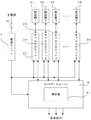
図5は、従来の多チャネル式測定装置の一例を示す構成図である。図において、1は電源ユニット、21〜28はそれぞれに測定動作を行うチャネルユニット、31〜38はチャネルユニット21〜28に対応して設けられた検出器(センサ)、4はチャネルユニット21〜28より得られる測定出力を受け、平均値などの演算処理を行うコントロールユニット、41は測定値などを表示する表示器である。図に示す装置は、8つの測定点を有する多チャネル式測定装置を例示している。
FIG. 5 is a configuration diagram illustrating an example of a conventional multi-channel measurement apparatus. In the figure, 1 is a power supply unit, 21 to 28 are channel units for performing measurement operations, 31 to 38 are detectors (sensors) provided corresponding to the
図に示すように、チャネルユニット21と検出器31とは一組の独立した測定装置(測定ユニット)を構成しており、残りのチャネルユニット22〜28と検出器32〜38も同様の測定装置(測定ユニット)を構成し、全部で8つの測定装置(測定ユニット)が併設されている。
また、図に示すように、チャネルユニット21〜28およびコントロールユニット4には、電源ユニット1から電源が供給されており、その断続はメインスイッチS0により行われている。
As shown in the figure, the
Further, as shown in the figure, the
チャネルユニット21〜28から得られた測定出力はコントロールユニット4に入力され、8点の平均値などが演算される。また、この演算出力は制御装置などにフィードバックされる。コントロールユニット4の出力としては、平均値の他に、警報動作に利用する接点出力などがある。
表示器41は各測定点における測定値や演算処理により求められた平均値などを表示する。
The measurement outputs obtained from the
The
しかしながら、上記のような従来装置においては、チャネルユニット21〜28を修理したり、検出器31〜38の交換や保守を行うためには、装置全体の電源を遮断しなければならない。
このため、1つの検出器の保守のみを行うような場合においても、保守の対象とならない他のチャネルに対しても電源を落とさなければならず、この間は測定が行われなくなってしまう。
特に、ジルコニア式酸素濃度計のように、検出器(ジルコニア式センサ)のウォーミングアップに長い時間を要する測定装置においては、一旦電源を落としてしまうと、再度測定を開始するまでに長い時間がかかり、装置の稼働率が著しく低下してしまう。
However, in the conventional apparatus as described above, in order to repair the
For this reason, even when only one detector is to be maintained, the power must be turned off to other channels that are not to be maintained, and measurement is not performed during this time.
In particular, in a measuring device that takes a long time to warm up the detector (zirconia type sensor), such as a zirconia type oxygen concentration meter, once the power is turned off, it takes a long time to start measurement again. The operating rate of the device is significantly reduced.
本発明は、上記のような従来装置の欠点をなくし、全体の電源を遮断することなく、個別のチャネルユニットおよび検出器の保守を行うことのできる多チャネル式測定装置およびその電源供給方法を実現することを目的としたものである。 The present invention eliminates the disadvantages of the conventional apparatus as described above, and realizes a multi-channel measurement apparatus and a power supply method thereof capable of maintaining individual channel units and detectors without shutting down the entire power supply. It is intended to do.
上記のような目的を達成するために、本発明の請求項1では、それぞれに検出器を有しその検出出力を利用して測定動作を行う複数のチャネルユニットと、これら複数のチャネルユニットに電源を供給する電源ユニットとを有する多チャネル式測定装置において、前記複数のチャネルユニット毎に設けられ各チャネルユニットに供給する電源を断続する複数のサブスイッチと、前記複数のチャネルユニットから得られる測定出力を演算処理して出力するとともに前記複数のサブスイッチの断続を制御するコントロールユニットとを具備することを特徴とする。 In order to achieve the above object, according to claim 1 of the present invention, a plurality of channel units each having a detector and performing a measurement operation using the detection output thereof, and power supplies to the plurality of channel units are provided. In a multi-channel measurement apparatus having a power supply unit for supplying power, a plurality of sub-switches provided for each of the plurality of channel units and intermittently supplying power to each channel unit, and a measurement output obtained from the plurality of channel units And a control unit for controlling the on / off of the plurality of sub-switches.
請求項2では、請求項1の多チャネル式測定装置において、前記コントロールユニットは、タッチパネル式の表示器を有し、このタッチパネルの操作により前記複数のサブスイッチの断続を制御することを特徴とする。 According to a second aspect of the present invention, in the multi-channel measurement device according to the first aspect, the control unit includes a touch panel display, and controls the intermittent operation of the plurality of sub switches by operating the touch panel. .
請求項3では、請求項1または2の多チャネル式測定装置において、前記コントロールユニットは、電源を遮断したチャネルユニットの測定出力を除いて演算処理を行うことを特徴とする。 According to a third aspect of the present invention, in the multi-channel measurement device according to the first or second aspect, the control unit performs a calculation process except for the measurement output of the channel unit whose power is cut off.
請求項4では、それぞれに検出器を有しその検出出力を利用して測定動作を行う複数の
チャネルユニットと、これら複数のチャネルユニットに電源を供給する電源ユニットとを
有する多チャネル式測定装置の電源供給方法において、前記複数のチャネルユニット毎に
供給する電源を断続するサブスイッチを設けるとともに、前記複数のチャネルユニットか
ら得られる測定出力を演算処理して出力するコントロールユニットにより前記複数のサブ
スイッチの断続を制御することを特徴とする。
According to a fourth aspect of the present invention , there is provided a multi-channel measurement apparatus having a plurality of channel units each having a detector and performing a measurement operation using the detection output, and a power supply unit that supplies power to the plurality of channel units. In the power supply method, a sub switch for intermittently supplying power to each of the plurality of channel units is provided, and a control unit that calculates and outputs measurement outputs obtained from the plurality of channel units is used to output the plurality of sub switches. It is characterized by controlling intermittentness.
請求項5では、請求項4の多チャネル式測定装置の電源供給方法において、前記コント
ロールユニットは、タッチパネル式の表示器を有し、このタッチパネルの操作により前記
複数のサブスイッチの断続を制御することを特徴とする。
According to a fifth aspect of the present invention, in the power supply method for the multi-channel measurement device according to the fourth aspect , the control unit has a touch panel display, and controls the intermittent operation of the plurality of sub switches by operating the touch panel. It is characterized by.
請求項6では、請求項4または5の多チャネル式測定装置の電源供給方法において、前
記コントロールユニットは、電源を遮断したチャネルユニットの測定出力を除いて演算処
理を行うことを特徴とする。
According to a sixth aspect of the present invention, in the method for supplying power to the multi-channel measurement device according to the fourth or fifth aspect , the control unit performs arithmetic processing except for the measurement output of the channel unit whose power is cut off.
このように、複数のチャネルユニット毎に供給する電源を断続するサブスイッチを設けるとともに、複数のチャネルユニットから得られる測定出力を演算処理して出力するコントロールユニットにより前記複数のサブスイッチの断続を制御するようにすると、全体の電源を遮断することなく、個別のチャネルユニットおよび検出器の保守を行うことのできる多チャネル式測定装置およびその電源供給方法を実現することができる。
したがって、保守の対象とならないチャネルユニットは引き続き測定動作を継続することができ、チャネルユニットや検出器の保守作業が装置全体としての稼働率を低下させてしまうことがない。
また、複数のサブスイッチの断続と連携させ、電源を遮断したチャネルユニットの測定出力を除いて演算処理を行うようにすると、保守作業により0や不定となった測定出力を無視することができ、平均値などを演算した場合にも、演算結果に誤差を生じてしまうことがない。
In this way, the sub-switch that interrupts the power supplied to each of the plurality of channel units is provided, and the control unit that controls and outputs the measurement output obtained from the plurality of channel units is controlled by the control unit. By doing so, it is possible to realize a multi-channel type measuring apparatus and its power supply method capable of maintaining individual channel units and detectors without shutting down the entire power source.
Therefore, the channel unit that is not subject to maintenance can continue the measurement operation, and the maintenance work of the channel unit and the detector does not reduce the operating rate of the entire apparatus.
In addition, if the calculation processing is performed except for the measurement output of the channel unit whose power is cut off in cooperation with the intermittent operation of multiple sub switches, the measurement output that becomes 0 or indefinite due to maintenance work can be ignored. Even when an average value or the like is calculated, no error occurs in the calculation result.
以下、図面を用いて、本発明の多チャネル式測定装置およびその電源供給方法を説明する。 Hereinafter, the multi-channel measurement device and the power supply method thereof according to the present invention will be described with reference to the drawings.
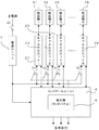
図1は、本発明の多チャネル式測定装置およびその電源供給方法の一実施例を示す構成図である。図において、前記図5と同様のものは同一符号を付して示す。S1〜S8はチャネルユニット21〜28毎に設けられ、各チャネルユニット21〜28に供給する電源を断続するサブスイッチで、その断続はコントロールユニット4により制御される。また、5はタッチパネルのような入力手段を有する表示器であり、測定値などの表示の他、測定装置における各種設定情報の入力や各チャネルユニット21〜28に対する電源供給の制御に使用される。
FIG. 1 is a configuration diagram showing an embodiment of a multi-channel measuring device and a power supply method thereof according to the present invention. In the figure, components similar to those in FIG. S <b> 1 to S <b> 8 are provided for each of the
装置の動作開始に際して、メインスイッチS0が投入されると、コントロールユニット4はサブスイッチS1〜S8をオンとして、チャネルユニット21〜28に電源を供給する。なお、コントロールユニット4において、通常、サブスイッチS1〜S8のデフォルトの設定はオンである。
When the main switch S0 is turned on at the start of operation of the apparatus, the control unit 4 turns on the sub switches S1 to S8 and supplies power to the
この結果、各チャネルユニット21〜28は測定動作を開始して、その測定出力がコントロールユニット4に入力される。コントロールユニット4では、各測定出力を基に、平均値などの演算処理を行う。
また、コントロールユニット4における演算処理の例としては、平均値演算の他に、最大の測定点の抽出、トレンドグラフの表示、警報出力の発生などがある。
As a result, each of the
In addition to the average value calculation, examples of calculation processing in the control unit 4 include extraction of the maximum measurement point, display of a trend graph, generation of an alarm output, and the like.
次に、チャネルユニット21〜28や検出器31〜38の保守作業に伴う電源制御動作について説明する。
図2は、表示器5における表示画面の一例を示す図である。図は、本発明の多チャネル式測定装置を酸素濃度計に応用した場合を例示したもので、画面には各測定点(CH1〜CH8)における酸素濃度の測定値が表示されている。図において、M1〜M5は表示画面中に設けられた操作キー(ソフトウエアキー)である。
Next, the power supply control operation accompanying the maintenance work of the
FIG. 2 is a diagram illustrating an example of a display screen on the
ここで、チャネルユニット21〜28や検出器31〜38の保守作業を実施する場合には、画面上の保守キー(M3)を押し、操作メニュー(図示せず)から電源制御モードを選択する。
Here, when performing maintenance work of the
図3は、電源制御モードにおける画面表示を表す図であり、図3(a)に示されるように、各チャネルユニット21〜28(CH1〜CH8)における電源状態は“Enable”(有効)となっている。
FIG. 3 is a diagram showing a screen display in the power control mode. As shown in FIG. 3A, the power state in each of the
保守すべきチャネルユニットを21(CH1)とすれば、選択キー(M2、M3)を操作して、CH1を選択し(図示の状態)、確定キー(M4)を押す。
これに応じて、画面には“Enable”(有効)、“Disable”(無効)の選択が表示されるので(図3(b))、選択を“Disable”(無効)に切り換え、確定キー(M4)を押す。
If the channel unit to be maintained is 21 (CH1), the selection key (M2, M3) is operated to select CH1 (the state shown in the figure), and the confirmation key (M4) is pressed.
In response to this, the selection of “Enable” or “Disable” (invalid) is displayed on the screen (FIG. 3B). Press M4).
この結果、図3(c)に示されるように、チャネルユニット21(CH1)の電源状態の設定は“Disable”(無効)となる。
このとき、コントロールユニット4はサブスイッチS1をオフとして、チャネルユニット21(CH1)に対する電源の供給を遮断する。
As a result, as shown in FIG. 3C, the setting of the power supply state of the channel unit 21 (CH1) becomes “Disable”.
At this time, the control unit 4 turns off the sub switch S1 to cut off the power supply to the channel unit 21 (CH1).
したがって、チャネルユニット21(CH1)の電源のみが遮断され、他のチャネルユニット22〜28(CH2〜CH8)は測定動作を続けたまま、チャネルユニット21(CH1)に対する保守作業を行うことが可能となる。
Therefore, only the power supply of the channel unit 21 (CH1) is cut off, and the
このとき、測定値の表示状態は、図4に示すように変化し、チャネルユニット21(CH1)が停止中であることが表示される。
図4の表示画面への移行は、図3(c)の状態から、戻るキー(M5)を押すことにより実現される。
At this time, the display state of the measured value changes as shown in FIG. 4, and it is displayed that the channel unit 21 (CH1) is stopped.
The transition to the display screen of FIG. 4 is realized by pressing the return key (M5) from the state of FIG.
また、この状態において、コントロールユニット4は、チャネルユニット22〜28(CH2〜CH8)の測定出力のみを使用して、平均値の演算を実施する。
したがって、チャネルユニット21(CH1)の保守作業のために、その測定出力が0または不定の状態となった場合にも、これが平均値演算に影響を与えてしまうことがなく、保守の対象とならないチャネルユニット22〜28(CH2〜CH8)を利用して、引き続き測定動作(平均値の演算)を継続することができる。
In this state, the control unit 4 calculates the average value using only the measurement outputs of the
Therefore, even if the measurement output becomes 0 or indefinite due to the maintenance work of the channel unit 21 (CH1), this does not affect the average value calculation and is not subject to maintenance. Using the
チャネルユニット21(CH1)に対する保守作業が終了し、チャネルユニット21(CH1)の測定動作を再開する場合には、前記図3に示した手順に従い、チャネルユニット21(CH1)の電源状態の設定を“Enable”(有効)に切り換える。 When the maintenance work for the channel unit 21 (CH1) is completed and the measurement operation of the channel unit 21 (CH1) is resumed, the power state of the channel unit 21 (CH1) is set according to the procedure shown in FIG. Switch to “Enable”.
この変更を受け、コントロールユニット4はサブスイッチS1をオンとして、チャネルユニット21(CH1)に対する電源の供給を再開する。
なお、チャネルユニット21(CH1)においては電源供給とともに測定動作を再開するが、ジルコニア式酸素濃度計のように、検出器(ジルコニア式センサ)のウォームアップ(加熱)が必要な場合には、ウォームアップが終了するまで測定動作の開始をホールドする。
In response to this change, the control unit 4 turns on the sub switch S1, and resumes the supply of power to the channel unit 21 (CH1).
In the channel unit 21 (CH1), the measurement operation is restarted when power is supplied. However, if the detector (zirconia sensor) needs to be warmed up (heated) like a zirconia oximeter, Hold the start of the measurement operation until the up is completed.
コントロールユニット4は、チャネルユニット21(CH1)の測定動作再開を待って、その測定値を表示器5に表示するとともに、平均値の演算を全チャネルユニット21〜28(CH1〜CH8)の測定出力を対象としたものに変更する。
The control unit 4 waits for the measurement operation of the channel unit 21 (CH1) to resume, displays the measurement value on the
なお、上記の説明においては、コントロールユニット4に電源管理の情報等を入力する手段としてタッチパネル(表示器5)を使用した場合を例示したが、入力手段はこれに限られるものではなく、マウス等のポインティングデバイスを使用することもできる。 In the above description, the case where the touch panel (display device 5) is used as means for inputting power management information and the like to the control unit 4 is illustrated, but the input means is not limited to this, and a mouse or the like is not limited thereto. Other pointing devices can also be used.
また、表示器5における画面展開は、図示のものに限らず、任意の構成を採用することができるものである。
さらに、接続するチャネルユニット21〜28の数を8点とした場合を例示したが、測定点の数はこれに限られるものではない。
Further, the screen development in the
Furthermore, although the case where the number of the
1 電源ユニット
21〜28 チャネルユニット
31〜38 検出器
4 コントロールユニット
41 表示器
5 表示器(タッチパネル)
S0 メインスイッチ
S1〜S8 サブスイッチ
M1〜M5 操作キー(ソフトウエアキー)
DESCRIPTION OF SYMBOLS 1 Power supply unit 21-28 Channel unit 31-38 Detector 4
S0 Main switch S1 to S8 Sub switch M1 to M5 Operation keys (software keys)
Claims (6)
トと、これら複数のチャネルユニットに電源を供給する電源ユニットとを有する多チャネ
ル式測定装置において、前記複数のチャネルユニット毎に設けられ各チャネルユニットに
供給する電源を断続する複数のサブスイッチと、前記複数のチャネルユニットから得られ
る測定出力を演算処理して出力するとともに前記複数のサブスイッチの断続を制御するコ
ントロールユニットとを具備してなる多チャネル式測定装置。 In a multi-channel measurement apparatus having a plurality of channel units each having a detector and performing a measurement operation using the detection output, and a power supply unit for supplying power to the plurality of channel units, the plurality of channels A plurality of sub-switches that are provided for each unit and that interrupts the power supplied to each channel unit, and a control that outputs and outputs the measurement output obtained from the plurality of channel units, and controls the on / off of the sub-switches A multi-channel measuring device comprising a unit.
作により前記複数のサブスイッチの断続を制御することを特徴とする請求項1に記載の多
チャネル式測定装置。 The multi-channel measurement apparatus according to claim 1, wherein the control unit includes a touch panel display, and controls the on / off of the plurality of sub switches by operating the touch panel.
算処理を行うことを特徴とする請求項1または2に記載の多チャネル式測定装置。 The multi-channel measurement apparatus according to claim 1, wherein the control unit performs arithmetic processing except for a measurement output of a channel unit whose power is cut off.
トと、これら複数のチャネルユニットに電源を供給する電源ユニットとを有する多チャネ
ル式測定装置の電源供給方法において、前記複数のチャネルユニット毎に供給する電源を
断続するサブスイッチを設けるとともに、前記複数のチャネルユニットから得られる測定
出力を演算処理して出力するコントロールユニットにより前記複数のサブスイッチの断続
を制御することを特徴とする多チャネル式測定装置の電源供給方法。 In a power supply method for a multi-channel measurement apparatus, which includes a plurality of channel units each having a detector and performing a measurement operation using the detection output, and a power supply unit that supplies power to the plurality of channel units. Providing a sub-switch for interrupting the power supplied to each of the plurality of channel units, and controlling the on / off of the plurality of sub-switches by a control unit that calculates and outputs the measurement output obtained from the plurality of channel units. A power supply method for a multi-channel type measuring apparatus.
作により前記複数のサブスイッチの断続を制御することを特徴とする請求項4に記載の多
チャネル式測定装置の電源供給方法。 5. The power supply method for a multi-channel measurement device according to claim 4 , wherein the control unit includes a touch panel display, and controls the on / off of the plurality of sub switches by operating the touch panel.
算処理を行うことを特徴とする請求項4または5に記載の多チャネル式測定装置の電源供
給方法。 Said control unit, the power supply method of a multi-channel measurement system according to claim 4 or 5, characterized in that performing arithmetic processing with the exception of the measurement output of the channel units off the power supply.
Priority Applications (2)
| Application Number | Priority Date | Filing Date | Title |
|---|---|---|---|
| JP2004213080A JP4590963B2 (en) | 2004-07-21 | 2004-07-21 | Multi-channel measuring device and power supply method thereof |
| US11/080,433 US20060019606A1 (en) | 2004-07-21 | 2005-03-16 | Multi-channel measurement system and power supplying method for the system |
Applications Claiming Priority (1)
| Application Number | Priority Date | Filing Date | Title |
|---|---|---|---|
| JP2004213080A JP4590963B2 (en) | 2004-07-21 | 2004-07-21 | Multi-channel measuring device and power supply method thereof |
Publications (2)
| Publication Number | Publication Date |
|---|---|
| JP2006030130A JP2006030130A (en) | 2006-02-02 |
| JP4590963B2 true JP4590963B2 (en) | 2010-12-01 |
Family
ID=35657874
Family Applications (1)
| Application Number | Title | Priority Date | Filing Date |
|---|---|---|---|
| JP2004213080A Active JP4590963B2 (en) | 2004-07-21 | 2004-07-21 | Multi-channel measuring device and power supply method thereof |
Country Status (2)
| Country | Link |
|---|---|
| US (1) | US20060019606A1 (en) |
| JP (1) | JP4590963B2 (en) |
Citations (6)
| Publication number | Priority date | Publication date | Assignee | Title |
|---|---|---|---|---|
| JPH06347442A (en) * | 1993-06-08 | 1994-12-22 | Yamazato Erekutoronaito Kk | Measuring device for oxygen activity in molten material and measuring method employing the device |
| JPH10227655A (en) * | 1997-02-14 | 1998-08-25 | Tokyo Gas Co Ltd | Sensor and method for correcting it |
| JPH1130581A (en) * | 1997-07-12 | 1999-02-02 | Horiba Ltd | Controller for gas analyzer system and its control method |
| JP2000146903A (en) * | 1998-11-12 | 2000-05-26 | Unisia Jecs Corp | Device for inspecting oxygen concentration detecting element |
| JP2002082993A (en) * | 2000-06-27 | 2002-03-22 | Asahi Kasei Corp | Remote attendance analysis method and terminal |
| JP2003066001A (en) * | 2001-08-23 | 2003-03-05 | Mitsubishi Electric Corp | Gas detector |
Family Cites Families (18)
| Publication number | Priority date | Publication date | Assignee | Title |
|---|---|---|---|---|
| US4819180A (en) * | 1987-02-13 | 1989-04-04 | Dencor Energy Cost Controls, Inc. | Variable-limit demand controller for metering electrical energy |
| US5589764A (en) * | 1991-03-05 | 1996-12-31 | Lee; Graham S. | Meter for measuring accumulated power consumption of an electrical appliance during operation of the appliance |
| JPH07103988B2 (en) * | 1991-05-10 | 1995-11-08 | トヨタ自動車株式会社 | Burner flame detector |
| JP3284606B2 (en) * | 1992-09-24 | 2002-05-20 | 石川島播磨重工業株式会社 | Ash melting furnace |
| US5572438A (en) * | 1995-01-05 | 1996-11-05 | Teco Energy Management Services | Engery management and building automation system |
| DE19781654B4 (en) * | 1996-03-15 | 2007-03-29 | Kabushiki Kaisha Toshiba, Kawasaki | A system for recovering metal from a resin and a metal circuit board and method for recovering metal from a circuit board having a resin and a metal as constituents |
| US20010010032A1 (en) * | 1998-10-27 | 2001-07-26 | Ehlers Gregory A. | Energy management and building automation system |
| US6528957B1 (en) * | 1999-09-08 | 2003-03-04 | Lutron Electronics, Co., Inc. | Power/energy management control system |
| US6633802B2 (en) * | 2001-03-06 | 2003-10-14 | Sikorsky Aircraft Corporation | Power management under limited power conditions |
| KR20040083514A (en) * | 2002-02-14 | 2004-10-02 | 얀마 가부시키가이샤 | Power source switching unit and power source management system comprising it |
| CN1656661A (en) * | 2002-03-28 | 2005-08-17 | 罗伯绍控制器公司 | Energy management system and method |
| US20050090915A1 (en) * | 2002-10-22 | 2005-04-28 | Smart Systems Technologies, Inc. | Programmable and expandable building automation and control system |
| JP2007510394A (en) * | 2003-10-24 | 2007-04-19 | スクエア・ディー・カンパニー | Intelligent power management control system |
| US7305905B2 (en) * | 2004-01-09 | 2007-12-11 | The Bergquist Torrington Company | Rotatable member with an annular groove for dynamic balancing during rotation |
| US7460930B1 (en) * | 2004-05-14 | 2008-12-02 | Admmicro Properties, Llc | Energy management system and method to monitor and control multiple sub-loads |
| US7570259B2 (en) * | 2004-06-01 | 2009-08-04 | Intel Corporation | System to manage display power consumption |
| US7161329B2 (en) * | 2005-04-20 | 2007-01-09 | Mcloughlin John E | Generator controlling system |
| JP4520959B2 (en) * | 2005-04-22 | 2010-08-11 | アイシン精機株式会社 | Power supply system |
-
2004
- 2004-07-21 JP JP2004213080A patent/JP4590963B2/en active Active
-
2005
- 2005-03-16 US US11/080,433 patent/US20060019606A1/en not_active Abandoned
Patent Citations (6)
| Publication number | Priority date | Publication date | Assignee | Title |
|---|---|---|---|---|
| JPH06347442A (en) * | 1993-06-08 | 1994-12-22 | Yamazato Erekutoronaito Kk | Measuring device for oxygen activity in molten material and measuring method employing the device |
| JPH10227655A (en) * | 1997-02-14 | 1998-08-25 | Tokyo Gas Co Ltd | Sensor and method for correcting it |
| JPH1130581A (en) * | 1997-07-12 | 1999-02-02 | Horiba Ltd | Controller for gas analyzer system and its control method |
| JP2000146903A (en) * | 1998-11-12 | 2000-05-26 | Unisia Jecs Corp | Device for inspecting oxygen concentration detecting element |
| JP2002082993A (en) * | 2000-06-27 | 2002-03-22 | Asahi Kasei Corp | Remote attendance analysis method and terminal |
| JP2003066001A (en) * | 2001-08-23 | 2003-03-05 | Mitsubishi Electric Corp | Gas detector |
Also Published As
| Publication number | Publication date |
|---|---|
| JP2006030130A (en) | 2006-02-02 |
| US20060019606A1 (en) | 2006-01-26 |
Similar Documents
| Publication | Publication Date | Title |
|---|---|---|
| EP1850440A4 (en) | Building energy management system | |
| JP2004233118A (en) | Environmental management system, environmental management method, and program for performing the method | |
| EP1862983A3 (en) | Remote control system | |
| EP1115082A3 (en) | Portable barcode printer with control and display for function keys | |
| MY135462A (en) | " power-saving apparatus and method for computer peripheral devices " | |
| EP1939694A3 (en) | Image forming apparatus comprising a malfunction detector and control method thereof | |
| JP4590963B2 (en) | Multi-channel measuring device and power supply method thereof | |
| JP2004060998A (en) | Energy-saving appliance | |
| CN102644616A (en) | Control system | |
| JP2002203582A5 (en) | ||
| US20140365014A1 (en) | Apparatus for setting degree of controllability for construction equipment | |
| CN1957796B (en) | Multifunction programmable manually operated blower | |
| KR101174361B1 (en) | Lighting control system for display the amount of electricity used | |
| JPH11167438A (en) | Power conservation device for display | |
| KR101528872B1 (en) | Apparatus for power controlling in electric range and method thereof | |
| CA2815750A1 (en) | Systems and methods for controlling a combustion engine | |
| JP2009250471A (en) | Hot water supply device | |
| KR940022236A (en) | Power saving device and control method of monitor | |
| KR20120091851A (en) | Energy control system | |
| JPS60246428A (en) | Power source controlling system of terminal equipment in information processing system | |
| JP7028599B2 (en) | Combustion system | |
| JP2011059788A (en) | Electric energy consumption reduction simulation system | |
| JP2007309534A (en) | Air supply and exhaust management control device for clean room | |
| JP2006078045A (en) | Remote control device of air conditioner | |
| CN116436104A (en) | Power supply device, system and air supply device of air supply device |
Legal Events
| Date | Code | Title | Description |
|---|---|---|---|
| A621 | Written request for application examination |
Free format text: JAPANESE INTERMEDIATE CODE: A621 Effective date: 20070515 |
|
| A131 | Notification of reasons for refusal |
Free format text: JAPANESE INTERMEDIATE CODE: A131 Effective date: 20100416 |
|
| A521 | Written amendment |
Free format text: JAPANESE INTERMEDIATE CODE: A523 Effective date: 20100611 |
|
| TRDD | Decision of grant or rejection written | ||
| A01 | Written decision to grant a patent or to grant a registration (utility model) |
Free format text: JAPANESE INTERMEDIATE CODE: A01 Effective date: 20100817 |
|
| A01 | Written decision to grant a patent or to grant a registration (utility model) |
Free format text: JAPANESE INTERMEDIATE CODE: A01 |
|
| A61 | First payment of annual fees (during grant procedure) |
Free format text: JAPANESE INTERMEDIATE CODE: A61 Effective date: 20100830 |
|
| FPAY | Renewal fee payment (event date is renewal date of database) |
Free format text: PAYMENT UNTIL: 20130924 Year of fee payment: 3 |
|
| R150 | Certificate of patent or registration of utility model |
Ref document number: 4590963 Country of ref document: JP Free format text: JAPANESE INTERMEDIATE CODE: R150 Free format text: JAPANESE INTERMEDIATE CODE: R150 |
|
| FPAY | Renewal fee payment (event date is renewal date of database) |
Free format text: PAYMENT UNTIL: 20140924 Year of fee payment: 4 |