JP4590591B2 - Connecting system and plug member - Google Patents
Connecting system and plug member Download PDFInfo
- Publication number
- JP4590591B2 JP4590591B2 JP2003302976A JP2003302976A JP4590591B2 JP 4590591 B2 JP4590591 B2 JP 4590591B2 JP 2003302976 A JP2003302976 A JP 2003302976A JP 2003302976 A JP2003302976 A JP 2003302976A JP 4590591 B2 JP4590591 B2 JP 4590591B2
- Authority
- JP
- Japan
- Prior art keywords
- plug
- female member
- male member
- head
- female
- Prior art date
- Legal status (The legal status is an assumption and is not a legal conclusion. Google has not performed a legal analysis and makes no representation as to the accuracy of the status listed.)
- Expired - Fee Related
Links
Images


Description
本発明は、たとえばパーマ用薬品、液体石鹸、シャンプー、インキ、塗料等の化学品、医薬品、飲料水等の液状体又はトナー、食品、洗剤等の粉体が充填される容器に用いられる連結システム及び閉栓部材に関する。 The present invention relates to a connecting system used for containers filled with powders such as chemicals such as permanent chemicals, liquid soaps, shampoos, inks and paints, liquids such as pharmaceuticals and drinking water, or powders such as toners, foods and detergents. And a closure member.
従来、液状体や粉体が充填される容器に用いられる再封止可能な連結システムとしては、例えば、図20に示すような連結システムがある(例えば、特許文献1参照。)。即ち、連結システムとして雌部材201とプラグ202と雄部材203とを備えているものが提案されている。雌部材201は上下方向に貫通した横断面円形導通路211を有しかつ容器の開口内に固定される。プラグ202は雌部材201に連結され、かつ雌部材201の上端部に着脱自在に係合して導通路211の上端開口を閉鎖しうる。雄部材203はプラグ202に係合する頭部231および頭部231の下方に連なる横断面環状の棒状部232を有しかつ雌部材201の導通路内に下方から抜き差し自在に差し込まれる。雄部材203の棒状部232には、その下端から上端部に至る流体通路233の周囲の部分に、雄部材203が上端位置に達した際に雌部材201の上端よりも上方に位置しかつ流体通路233を外部に通じさせる貫通孔234が形成されている。雄部材203を雌部材201の導通路211内に挿入して上昇させることにより、その頭部231がプラグ202に係合するとともにプラグ202が雌部材201の上端部から外れ、かつ貫通孔234の少なくとも一部が雌部材201上端よりも上方に位置し、容器200が開栓され、内容物の注出入ができる。雄部材203を下降させることにより、頭部231と係合しているプラグ202が下降させられるとともに雌部材201の上端部に係合させられ流体通路233の上端開口が閉鎖され、かつ雄部材203の頭部231がプラグから外れるようになされている。
Conventionally, as a resealable connection system used for a container filled with a liquid or powder, for example, there is a connection system as shown in FIG. 20 (see, for example, Patent Document 1). That is, a connection system including a
この種の容器での充填方法は、一般的に、予め、パウチを雌部材にヒートシールを行なった後、図1に示すように、雌部材を容器の上部に位置にさせて、把持させ、雄部材の機構を備えたバキュームノズルを雌部材の導通路に挿入して、容器内の脱気を行なう。次に雄部材の機構を備えた充填ノズルにより内容物の充填を行なう。これにより容器内に空気が入らず、空気中の酸素による内容物への影響を抑制できる。また、雌部材201とプラグ202は結合されている為に、一体成形でき、充填工程においてキャップの取り付け工程を省くことができる。ところが、プラグ202が雌部材201と一体化されているため、プラグ202の上昇できる距離が制限され、雄部材201の貫通孔234を大きく設けることができない。そのため、高粘度の液体を充填させる場合、充填速度を高速にできず、充填時間が長時間必要であり、生産性が低下する問題点がある。
The filling method in this type of container is generally pre-heat-sealed to the female member in advance, and then, as shown in FIG. A vacuum nozzle provided with a male member mechanism is inserted into the conduction path of the female member to deaerate the inside of the container. Next, the contents are filled by a filling nozzle having a male member mechanism. Thereby, air does not enter into the container, and the influence on the contents due to oxygen in the air can be suppressed. Further, since the
また、内容物にトナーなどの粉体(例えば、特許文献2参照。)や高粘度の液体を用いた場合、吐出口付近で粉体の目詰まり(ブロッキング)や流動性不足でフィルムが口を塞いでしまい、容器に内容物が残留するという問題点もある。 In addition, when powder such as toner (for example, see Patent Document 2) or high-viscosity liquid is used as the content, the film may clog due to clogging (blocking) of powder or insufficient fluidity near the discharge port. There is also a problem that the contents remain in the container due to blocking.
本発明は上記の課題を解決するためになされたものであり、高粘度の液体を高速で充填可能にし、また、粉体をムラなく排出させる連結システム及び閉栓部材を提供することを目的とする。 The present invention has been made to solve the above-described problems, and an object of the present invention is to provide a connection system and a plugging member that can be filled with a high-viscosity liquid at a high speed and can discharge powder uniformly. .
第1の課題解決手段に係る発明は、貫通した導通路を有しかつ容器の流入出口を構成する雌部材と、雌部材と一体的に成形され、かつ雌部材の容器内側に存する一方端部に着脱自在に係合して導通路の容器内の開口を閉鎖しうるプラグと、プラグに係合可能な頭部および頭部に連なる棒状部を有し、かつ容器外側に存する他方端部から雌部材の導通路内に抜き差し自在に差込まれる雄部材とを備えており、雄部材の棒状部の端部から頭部近傍まで、貫通した流体通路が形成され、雄部材を雌部材の導通路内に挿入して押し込むことにより、頭部がプラグに係合するとともに、プラグが雌部材の前記一方端部から外れ、流体通路の頭部側開口の少なくとも一部がプラグ及び雌部材により閉鎖されない場所に位置して容器内側から頭部開口及び流体通路を経て容器外側の棒状部の端部に至る流入出口が形成され、さらに雄部材を押し込むことにより、雌部材とプラグとが切り離され、雄部材を引き抜く際に、頭部に係合されているプラグが引き寄せられるとともに、雌部材の前記一方端部に係合させられて導通路の容器内側の開口が閉鎖され、雄部材を引き抜くことにより、雄部材の頭部がプラグから外れるようになされている連結システムを提供する。
The invention according to the first problem solving means comprises a female member forming the inflow outlet of having and container guide passage through transmural are molded female member integrally with, and one end existing in the container inside of the female member A plug that can be detachably engaged with the part to close the opening in the container of the conduction path, a head that can be engaged with the plug, and a rod-like part connected to the head, and the other end located outside the container From the end of the rod-shaped portion of the male member to the vicinity of the head, and the male member is connected to the female member. By inserting and pushing into the conduction path, the head engages with the plug, the plug is detached from the one end of the female member, and at least a part of the opening on the head side of the fluid passage is formed by the plug and the female member. Head opening and flow from inside the container An inlet / outlet is formed through the passage to the end of the rod-shaped part outside the container, and by pushing the male member further, the female member and the plug are separated, and when the male member is pulled out, it is engaged with the head. The plug is drawn and engaged with the one end of the female member to close the opening inside the container of the conduction path. By pulling out the male member, the head of the male member is detached from the plug. Provide a linkage system.
第2の課題解決手段に係る発明は、第1の課題解決手段において、雌部材とプラグを一体成形するための連結部材を有し、連結部材に断面積が近傍より小さく形成されている切断部が設けられている連結システムを提供する。 The invention according to the second problem-solving means has a connecting member for integrally forming the female member and the plug in the first problem-solving means, and the connecting member has a cross-sectional area smaller than the vicinity thereof. A connection system is provided.
第3の課題解決手段に係る発明は、第1または第2の解決手段において、プラグがアジテータを有し、雌部材の導通路内に雄部材を挿入して、プラグと雄部材を係合させ、雄部材を回転させることにより、アジテータを回転することを特徴とする連結システムを提供する。 The invention according to the third problem solving means is the first or second solution means, wherein the plug has an agitator, the male member is inserted into the conduction path of the female member, and the plug and the male member are engaged. The coupling system is characterized in that the agitator is rotated by rotating the male member.
第4の課題解決手段に係る発明は、第1から第2のいずれかの解決手段において、雄部材の頭部側開口が雌部材とプラグとを切り離して雄部材を押し込むことにより雌部材で閉鎖されない開口面積を大きくできるよう構成されていることを特徴とする連結システムを提供する。 In the invention according to the fourth problem solving means, in any one of the first to second solving means, the head side opening of the male member is closed by the female member by separating the female member and the plug and pushing the male member. Provided is a connection system characterized in that it is configured to increase an opening area that is not performed.
第5の課題解決手段に係る発明は、第1から第4のいずれかの解決手段において、容器に設けられて容器外部から容器内部に通じる導通路が形成されている雌部材と、導通雄部材を雌部材の導通路に挿入する際、プラグに雄部材が嵌入するときの抗力よりも雌部材とプラグが係合する力が大きくなるよう形成され、雄部材を引き抜く際、プラグが雌部材に係合するときの抗力よりも雄部材とプラグが係合する力が大きくなるよう形成されていることを特徴する連結システムを提供する。 The invention according to the fifth problem-solving means is any one of the first to fourth solving means, wherein a female member provided in the container and formed with a conduction path leading from the outside of the container to the inside of the container, and a conductive male member When the male member is inserted into the conduction path of the female member, the force for engaging the female member with the plug is larger than the drag force when the male member is fitted into the plug. Provided is a connection system characterized in that a force for engaging a male member and a plug is larger than a drag force when engaging.
第6の課題解決手段に係る発明は、容器に設けられて容器外部から容器内部に通じる導通路が形成されている口部材と、導通路の容器内部側で導通路を閉じるためのプラグとが連結部材を介して一体的に成形されてなる閉栓部材であって、プラグが、容器へ内容物を充填するために導通路に挿入される開栓部材に係合する第1係合部と、口部材に係合する第2係合部とを備え、開栓部材が第1係合部に係合した状態で開栓部材を引き抜くとき、開栓部材が第1係合部から外れるのに要する力よりも第2係合部が口部材と係合するのに要する力が小さく構成され、充填時にプラグの第1係合部に開栓部材が係合した後、連結部材を切断してプラグと口部材とを分離可能に構成され、連結部材が切断された状態で口部材から開栓部材を引き抜く際に、プラグが第2係合部に係合した後に第1係合部から開栓部材が外れるように構成されていることを特徴とする閉栓部材を提供する。
The invention according to the sixth problem solving means is provided with a mouth member provided in the container and formed with a conduction path leading from the outside of the container to the inside of the container, and a plug for closing the conduction path on the container inside side of the conduction path. A closure member formed integrally with a connecting member, wherein the plug engages with a closure member inserted into the conduction path in order to fill the container with the contents; A second engaging portion that engages with the mouth member, and when the plug member is pulled out in a state where the plug member is engaged with the first engaging portion, the plug member is disengaged from the first engaging portion. force the second engaging portion than the force required is required to engage the mouth member is made smaller, unplugging member to the first engagement portion of the plug after engagement, by cutting the connecting member at the time of filling Te is configured to be separated and the plug and the mouth member, when removing the cap removal member from the mouth member in a state where the connecting member is cut Provides a cap member, wherein a plug is configured such that cap removal member from the first engagement portion after engagement with the second engaging portion disengages.
第7の課題解決手段に係る発明は、第6の解決手段において、連結部材に断面積が近傍より小さく形成されている切断部が設けられていることを特徴とする閉栓部材を提供する。 The invention according to a seventh problem-solving means provides the plug-closing member according to the sixth solving means, wherein the connecting member is provided with a cutting portion having a cross-sectional area smaller than the vicinity.
第8の課題解決手段に係る発明は、第6または第7の解決手段において、プラグが、アジテータと、口部材の導通路内に回動自在に挿入される開栓部材に掛止して開栓部材の回動に連れて共に回動するための掛止部とを備えることを特徴とする閉栓部材を提供する。 According to an eighth aspect of the present invention, in the sixth or seventh aspect, the plug is engaged with the agitator and the opening member that is rotatably inserted into the conduction path of the mouth member. There is provided a closure member comprising a latching portion for turning together with the turning of the stopper member.
第9の課題解決手段に係る発明は、第6または第7の解決手段において、開栓部材の頭部側開口が、口部材とプラグとを切り離して開栓部材を押し込むことにより、口部材で閉鎖されない開口面積を大きくできるよう構成されていることを特徴とする閉栓部材を提供する。 The invention relating to the ninth problem-solving means is the sixth or seventh solving means, wherein the head side opening of the opening member separates the opening member and the plug and pushes the opening member, thereby Provided is a closing member configured to increase an opening area that is not closed.
第10の課題解決手段に係る発明は、第6から第9のいずれかの解決手段において、開栓部材を口部材の導通路に挿入する際、プラグの第1係合部に開栓部材が嵌入するときの抗力よりも口部材とプラグの第2係合部が係合する力が大きくなるよう形成されていることを特徴する閉栓部材を提供する。 The invention according to a tenth problem solving means is that in any one of the sixth to ninth solving means, when the opening member is inserted into the conduction path of the mouth member, the opening member is provided at the first engaging portion of the plug. Provided is a closing member characterized in that a force with which a mouth member and a second engaging portion of a plug are engaged is greater than a drag force when fitted.
第1の課題解決手段に係る発明は、一体成形した雌部材とプラグを切り離すことにより、プラグによる制限なく、流体通路の頭部側開口を雌部材により閉鎖されない位置に配置でき、雄部材の流体通路の頭部側開口を大きく設けることができ、内容物の容器への充填時間を短縮できる連結システムを提供することができるという効果がある。 In the invention according to the first problem solving means, by separating the integrally formed female member and the plug, the head side opening of the fluid passage can be disposed at a position not closed by the female member without restriction by the plug, and the fluid of the male member There is an effect that it is possible to provide a connection system capable of providing a large opening on the head side of the passage and shortening the filling time of the contents into the container.
第2の課題解決手段に係る発明は、雄部材を差し込むことにより、一体成形した雌部材とプラグを切断部で切り離せるため、第1の課題解決手段に係る発明の効果に加えて、容器の充填工程、もしくはバキューム工程において、小さな力で切断することができ、別途、切断工程、閉栓工程を設ける必要がない連結システムを提供する。 In the invention according to the second problem solving means, by inserting the male member, the integrally formed female member and the plug can be separated at the cutting portion. Therefore, in addition to the effects of the invention according to the first problem solving means, Provided is a connection system that can be cut with a small force in a filling step or a vacuum step and that does not require a separate cutting step and capping step.
第3の課題解決手段に係る発明は、プラグにアジテータ機構を設けることにより、雄部材とプラグを嵌合した状態で、雄部材を回転させ、プラグのアジテータ機構を回転させ、内容物を確実に排出することができる連結システムを提供する。 In the invention according to the third problem solving means, by providing the plug with the agitator mechanism, the male member is rotated in a state where the male member and the plug are fitted, and the agitator mechanism of the plug is rotated, so that the contents can be reliably obtained. Provide a linkage system that can be discharged.
第4の課題解決手段に係る発明は、雌部材とプラグとが切り離された後に流入出可能な面積を大きくすることができる連結システムを提供する。 The invention according to the fourth problem-solving means provides a connection system that can increase the area that can flow in and out after the female member and the plug are separated.
第5の課題解決手段に係る発明は、雌部材とプラグとが切り離された後においても、雄部材により繰り返しプラグを雌部材から外したり雌部材に嵌めたりでき、プラグによる導通路の開閉を繰り返し行わせることができるという効果がある。 In the invention according to the fifth problem solving means, even after the female member and the plug are separated from each other, the male member can repeatedly remove the plug from the female member or fit the female member, and the plug repeatedly opens and closes the conduction path. There is an effect that it can be done.
第6の課題解決手段に係る発明は、一体成形した口部材とプラグを切り離すことにより、プラグによる制限なく、流体通路の頭部側開口を口部材により閉鎖されない位置に配置でき、充填ノズル等の開栓部材の流体通路の頭部側開口を大きく設けることができ、内容物の容器への充填時間を短縮できる閉栓部材を提供することができるという効果がある。
In the invention according to the sixth problem solving means, by separating the integrally formed mouth member and the plug, the head side opening of the fluid passage can be disposed at a position not closed by the mouth member without restriction by the plug , The opening on the head side of the fluid passage of the opening member can be provided large, and there is an effect that it is possible to provide a closing member that can shorten the filling time of the contents into the container.
第7の課題解決手段に係る発明は、開栓部材を差し込むことにより、一体成形した雌部材とプラグを切断部で切り離せるため、第6の課題解決手段に係る発明の効果に加えて、容器の充填工程、もしくはバキューム工程において、小さな力で切断することができ、別途、切断工程、閉栓工程を設ける必要がない閉栓部材を提供する。
In the invention according to the seventh problem solving means, since the female member and the plug integrally formed can be separated at the cutting portion by inserting the opening member , in addition to the effect of the invention according to the sixth problem solving means, the container In the filling process or the vacuum process, a plug member that can be cut with a small force and does not need to be provided separately with a cutting process and a plugging process is provided .
第8の課題解決手段に係る発明は、プラグにアジテータ機構を設けることにより、開栓部材とプラグを嵌合した状態で、開栓部材を回転させ、プラグのアジテータ機構を回転させ、内容物を確実に排出することができる閉栓部材を提供する。 In the invention according to the eighth problem solving means, by providing an agitator mechanism in the plug, the plug opening member is rotated in a state where the plug opening member and the plug are fitted, the plug agitator mechanism is rotated, and the contents are Provided is a closing member that can be reliably discharged.
第9の課題解決手段に係る発明は、口部材とプラグとが切り離された後に流入出可能な面積を大きくすることができる閉栓部材を提供する。 The invention relating to the ninth problem solving means provides a closure member capable of increasing the area that can be flowed in and out after the mouth member and the plug are separated.
第10の課題解決手段に係る発明は、連結部材が切断された後においても、開栓部材により繰り返しプラグを雌部材から外したり雌部材に嵌めたりでき、プラグによる導通路の開閉を繰り返し行わせることができるという効果がある。
The invention according to a tenth problem solving means, after the coupling member is disconnected also, can or fitted into the female member or disconnect the repetition plug from the female member by unplugging member, thereby repeatedly opening and closing of the conductive paths by plug There is an effect that can be.
以下、図面に基づき、この発明に係る一実施の形態について説明する。図1は本願発明の一実施の形態で用いられる連結システムを備えた包装用容器の充填工程の図である。図2は連結システムの雌部材の正面図であり、図3は連結システムの雌部材の側面図、図4は連結システムの雌部材の底面図、図5は図4におけるA−A線の断面図である。図6は連結システムの雄部材の正面図、図7は連結システムの雄部材の底面図、図8は図7におけるB−B線の断面図である。 Hereinafter, an embodiment according to the present invention will be described with reference to the drawings. FIG. 1 is a diagram of a filling process of a packaging container provided with a connection system used in an embodiment of the present invention. 2 is a front view of a female member of the connection system, FIG. 3 is a side view of the female member of the connection system, FIG. 4 is a bottom view of the female member of the connection system, and FIG. 5 is a cross-sectional view taken along line AA in FIG. FIG. 6 is a front view of a male member of the connection system, FIG. 7 is a bottom view of the male member of the connection system, and FIG. 8 is a cross-sectional view taken along line BB in FIG.
この発明の一実施の形態で用いられる連結システムは、3つの構成要素からなる。雌部材1と、雌部材1に連結しうる雄部材3と、雌部材1を閉鎖するプラグ2である。雌部材1およびプラグ2は、雄部材3との連結部材としてだけでなく、雌部材(口部材)1とプラグ2のみでクロージャー(閉栓部材)としての役割も果たす。雌部材1とプラグ2は、射出成形などの適切な成形により一体のプラスチック部材として製造される。プラスチックとしては、熱可塑性プラスチック、例えば、ポリエチレン、ポリプロピレンなど可撓性を有するものが適している。雄部材3は金属またはプラスチック部材として製造され、減圧脱気用バキュームノズル、充填用ノズル、および充填後に雌部材1に接続するスパウト等の開栓部材であり、雄部材3の構成を備えたものであれば良い。
The connection system used in one embodiment of the present invention is composed of three components. A
雌部材1は、例えば液状体が充填される袋101の開口内に固定され、かつ袋101の内側から外側まで貫通した導通路4を有する。プラグ2は雌部材1に2本の可撓性連結部材20を介して連結され、かつ雌部材1の袋101の内側に存する導通路4の一方端部である開口部11に着脱自在に係合して閉鎖しうる。雄部材3はプラグ2と係合する頭部32および頭部32に連なる横断面環状の棒状部37を有しかつ雌部材1の導通路4内に他方端から抜き差し自在に差し込まれる。
The
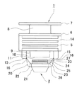
雌部材1は、液状体用袋101に融着や接着等の適宜固定手段で固定される2つの側面を形成するための舟形の基部5と、基部5の一方の側に接する第1フランジ6とその上部の第2フランジ7に挟まれ、充填工程の際、把持具301で把持される被把持部8とからなり、基部5の他方の側には、先端に向かって漸次外径が小さくなっているテーパ筒状部9およびテーパ筒状部9の先端と同じ外径の小径部10からなる開口部11が形成されている。開口部11の内周面には環状内方突出部12が全周にわたって形成されている。環状内方突出部12の液状体用袋101内側に存する開口側には、開口に向かって漸次内径が大きくなっている開口部内面13が形成されている。各基部5には複数のリブ14が一体に成形されている。第1フランジ6は第1フランジ6の基部5側の面まで液状体用袋101を差し込み固定させるためのものである。
The
プラグ2は雌部材1の基部5に接する支柱15から突出する2本の可撓性連結部材20を介して雌部材1と一体に成形されてなる。可撓性連結部材20のうち支柱15に接続されている部分に切断部16が形成されている。切断部16は可撓性連結部材20や支柱15よりも細く、容易に雌部材とプラグを切断することができる。また、切断部16を設けることにより、切断される部位を特定できるので、予め可撓性連結部材20の切断後の形状を定めることができる。可撓性連結部材20との連結部分を挟んでプラグ2の一方の側にはスカート部21が設けられ、他方の側には雌部材1の開口部11と嵌合することによって開口部11を閉じる主嵌合部(第2係合部)22が設けられている。即ち、プラグ2外周の主嵌合部22に対し、雌部材1の開口部11が主受容部となっている。主嵌合部22には、雌部材1の環状内方突出部12と掛止めされる環状突出部23が全周にわたり形成され、スカート部21に向かって、環状凹溝24、さらに開口部内面13との隙間を封止する膨出部25が液密状に嵌り合うように形成されている。さらに雌部材1の開口部11の端面に液密状に接する停止面26が形成されている。プラグ2の主嵌合部22の他方には、全周にわたる環状凹溝24と開口部11内面を環状凹溝24に導くため先端に向けて、漸次外径が小さくなっている傾斜部27が形成されている。プラグ2の内面には雄部材1の頭部32と係合する受容部(第1係合部)28が形成されている。
The
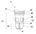
雄部材3はその先端部31の先に頭部32を備えている。頭部32は先端側から突出部の当接面33、係合面34を有し、先端部31には頭部32の上に環状凹部35、貫通孔36を有する。当接面33にはエアを抜く為の溝41が設けられている。先端部31の隣りには、その内部に頭部付近から他方端に至る流体通路39が設けられた棒状部37が形成されている。流体通路39は頭部側開口の貫通孔36を介して外部と繋がっている。棒状部37と先端部31の間にはOリング40を取り付けることができるように環状溝部38が設けられている。このOリング40は必ずしも必要ではないが、このOリング40により雌部材1の流体通路40と雄部材3の棒状部外周面との間が完全にシールされる。
The
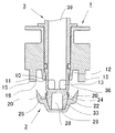
この発明の一実施の形態で用いられる連結システムの動作について図を用いて説明する。図9は雌部材の導通路に雄部材を挿入する状態の図1の連結システムの断面図である。図10はプラグが雄部材と係合している状態の連結システムの断面図である。雌部材1の導通路4内に雄部材3を挿入して押し込む場合、雄部材3の頭部32がプラグ2の受容部28に嵌合し、受容部内面29に雄部材の当接面33が当接する。
The operation of the connection system used in the embodiment of the present invention will be described with reference to the drawings. FIG. 9 is a cross-sectional view of the connection system of FIG. 1 with the male member inserted into the conduction path of the female member. Figure 10 is a cross-sectional view of the coupling system in a state where the plug is engaged with the male member. If pushed by inserting the
さらに、雄部材3を押し込むと、雄部材3がプラグ2を押す力が、プラグ2の主嵌合部22と雌部材1の開口部内面13との係合する力を上回り、プラグ2が雌部材1の開口部11から外れる。このとき、プラグ2の受容部内面29に雄部材3の当接面33が当接する形状であるので、プラグ2が傾くことなく押される。雄部材3によりプラグ2を押し、貫通孔36が開口部11の小径部10よりも下方に位置すると容器内へ雄部材3の流体通路39と貫通孔36を介して容器内の脱気、もしくは、液体、粉体の出し入れが行なえるようになる。
Further, when the
さらに、雄部材3を押し込むと、図11に示すように雌部材1とプラグ2とを繋ぐ可撓性連結部材20が切断部16で切断され、雌部材1とプラグ2が切り離される。雌部材1とプラグ2とが切り離されるため、可撓性連結部材20の長さに制限されることなく、プラグ2をより下方に移動させることができ、プラグ2と係合した雄部材1の貫通孔36の全体が開口部11の小径部10により閉鎖されない場所に位置させることが可能になる。
Further, when the
容器に液体、粉体の内容物を充填する工程において、貫通孔36の一部分しか小径部10により閉鎖されない場所に位置しないと、貫通孔36において流路が狭められるため、充填速度を高速にすることができず、充填に時間を要することになる。内容物の粘度が高くなればなるほど、生産性が低下してしまう。プラグ2と雌部材1を切り離すことにより、貫通孔36のより大部分を小径部10により閉鎖されない場所に位置させることができる為に、流路が狭められることなく、高速に内容物を充填することが可能である。
In the step of filling the container with the contents of liquid and powder, if only a part of the through
図12に示すように、雄部材3を引き抜くと、頭部32の当接面33とプラグ2の受容部内面29が当接されているため、プラグ2も引っ張られる。プラグ2の主嵌合部22が開口部11に嵌る際、プラグ2の傾斜部27は先端ほど径が小さい為、小さな抵抗で開口部11に進入する。また、開口部11に深く進入するほど、開口部内面13と強く接して、大きな抵抗がかかるため、雄部材3を引っ張るのに要する力が大きくなる。雌部材3の環状内方突出部12にプラグ2の環状凹溝24とが係合することにより、プラグ2と雌部材1が嵌合される。さらにプラグの停止面26と小径部10が接し、さらに雄部材3を引き上げることにより、停止面26と小径部10とが接する力が頭部32と受容部内面29との嵌合する力を上回り、図13に示すように、プラグ2の受容部28から頭部32が抜ける。
As shown in FIG. 12, when the
以上説明したように、雄部材3を挿入する際、プラグ2に雄部材3が嵌入するときの抗力より、雌部材1とプラグ2が係合する力が大きく、かつ雄部材3を引き抜く際、プラグ2が雌部材1に嵌るときの抗力より、雄部材3とプラグ2が係合する力が大きくなるよう構成されているため、可撓性連結部材20が切れた状態でも、開栓と閉栓を繰り返すことができる。
As described above, when the
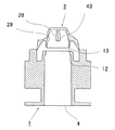
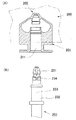
図14は本発明のさらに他の実施の形態に係る連結システムの雌部材の正面図、図15は雌部材の側面図、図16は雌部材の平面図である。図17は雌部材のC−C線の断面図であり、図18は雌部材のD−D線の断面図である。先の実施の形態におけるプラグ2のスカート部21にアジテータ機構42を備えている。プラグ2の受容部内面29に内方突出部43が掛止め部として少なくとも一つ以上設けられている。アジテータの形状は特に限定されず、フィン状、スクリュウ状など、通常用いられるアジテータ機構のもので良い。
Figure 14 is front view of the female member of the coupling system according to another embodiment of the present invention, FIG 15 is a side view of the female member, Figure 16 is a planar surface view of the female member. FIG. 17 is a cross-sectional view taken along line CC of the female member, and FIG. 18 is a cross-sectional view taken along line DD of the female member. The
雌部材1の導通路4内に雄部材3を挿入して押し込む場合、雄部材3の頭部32がプラグ2の受容部28に嵌合されるとともに、プラグ2の受容部内面29に設けられた内方突出部43が雄部材3の頭部32の当接面33に設けられた溝41内に嵌る。通常、溝41はプラグの受容部28に頭部32を嵌合させる際、プラグ2の受容部28の空気を抜く働きもする。
When the
雄部材3を雌部材1に押し込むと、受容部内面29に雄部材3の当接面33が当接して、雄部材3がプラグ2を押す力が、プラグ2の主嵌合部22と雌部材1の開口部内面13との係合力を上回ったところで、プラグ2が雌部材1の開口部11から外れる。
When the
雄部材3を更に押し込むことにより、図19に示すように、プラグ2と雌部材1が切断部16で切り離される。プラグ2の受容部内面29の内方突出部43が雄部材3の当接面33の溝41と嵌合しているので、雄部材3を軸方向に回転させると、雄部材3が空回りすることなく、雄部材3を回転軸として、プラグ2が回転する。プラグ2に備え付けられたアジテータ42により内容物302が雄部材の貫通孔36に掻き寄せられ、排出することができる。
When the
1 雌部材
2 プラグ
3 雄部材
4 導通路
5 基部
11 開口部
16 切断部
20 可撓性連結部材
22 主嵌合部
28 受容部
31 先端部
32 頭部
36 貫通孔
39 流体通路
101液状体袋
102シール部
DESCRIPTION OF
Claims (3)
可撓性連結部材(20)に、雌部材(1)とプラグ(2)との切り離しを容易にするために断面積が近傍より小さく形成されている切断部(16)が設けられ、
雄部材(3)の頭部側開口(36)は、雄部材(3)を雌部材(1)の導通路(4)内に挿入して押し込んだ際、雌部材(1)から外れたプラグ(2)が可撓性連結部材(20)を介して雌部材(1)と一体化された状態では、同開口(36)の一部が雌部材(1)によって閉鎖されるが、切断部(16)を破断させうる押し込み力を雄部材(3)に加えて、プラグ(2)を雌部材(3)から切り離し、雄部材(3)をさらに容器内側へ移動させることにより、雌部材(1)によって閉鎖されない開口面積が大きくなるように形成され、
雌部材(1)の前記一方端部(11)、プラグ(2)および雄部材(3)の頭部(32)は、雄部材(3)を雌部材(1)の導通路(4)に挿入する際、プラグ(2)に雄部材(3)の頭部(32)が係合するのに要する力よりも雌部材(1)の前記一方端部(11)からプラグ(2)が外れるのに要する力が大きくなるように形成されているとともに、雄部材(3)を雌部材(1)の導通路(4)から引き抜く際、プラグ(2)が雌部材(1)の前記一方端部(11)に係合するのに要する力よりも雄部材(3)の頭部(32)がプラグ(2)から外れるのに要する力が大きくなるように形成されており、
プラグ(2)がアジテータ(42)を有し、雌部材(1)の導通路(4)内に雄部材(3)を挿入して、プラグ(2)と雄部材(3)の頭部(32)を係合させ、さらにプラグ(2)を雌部材(1)から切り離した状態で、雄部材(3)を回転させることにより、アジテータ(42)が回転することを特徴とする、連結システム。 A female member that constitutes the flow outlet of a through the conductive path (4) and the container (101) (1), the flexible connecting member female member (1) through (20) and integrally molded A plug (2) capable of detachably engaging with one end (11) existing inside the container of the female member (1) and closing the opening in the container of the conduction path (4) ; and the plug (2) A head portion (32) that can be engaged with the head portion (32) and a rod-shaped portion (37) that is continuous with the head portion (32) , and is inserted into and removed from the other end portion outside the container into the conduction path (4) of the female member (1). A male member (3) that is freely inserted, a fluid passage (39) penetrating from the end of the rod-like portion (37) of the male member (3) to the vicinity of the head (32 ) is formed, by pushing by inserting the male member (3) to the conductive path (4) of the female member (1), together with the head (32) engages the plug (2), the plug (2) is a female member ( wherein one end portion of the 1) deviates from (11), from the container interior through the head side opening of the male member (3) (36) and fluid passages (39) Rod-like portion of Utsuwasotogawa (37) flows into the outlet leading to the end of is formed, whereas, by pulling out the male member (3) conductive path of the female member (1) to (4), engaging the head (32) The plug (2) fitted together is drawn and engaged with the one end (11) of the female member (1) to close the opening inside the container of the conduction path (4) , and the male member ( In the connection system in which the head (32 ) of 3) is made to come off from the plug (2) ,
The flexible connecting member (20) is provided with a cutting portion (16) having a cross-sectional area smaller than the vicinity in order to facilitate separation of the female member (1) and the plug (2),
The head side opening (36) of the male member (3) is a plug that is detached from the female member (1) when the male member (3) is inserted into the conduction path (4) of the female member (1) and pushed. In the state where (2) is integrated with the female member (1) through the flexible connecting member (20), a part of the opening (36) is closed by the female member (1), (16) Applying a pushing force capable of breaking the male member (3), disconnecting the plug (2) from the female member (3), and moving the male member (3) further inside the container, 1) formed so as to increase the opening area that is not closed,
The one end (11) of the female member (1), the plug (2), and the head (32) of the male member (3) are connected to the conduction path (4) of the female member (1). During insertion, the plug (2) is disengaged from the one end (11) of the female member (1) than the force required for the head (32) of the male member (3) to engage the plug (2). And the plug (2) is connected to the one end of the female member (1) when the male member (3) is pulled out of the conduction path (4) of the female member (1). The force required to disengage the head (32) of the male member (3) from the plug (2) is greater than the force required to engage the part (11),
The plug (2) has an agitator (42), the male member (3) is inserted into the conduction path (4) of the female member (1), and the plug (2) and the head of the male member (3) ( 32) is engaged, and the agitator (42) is rotated by rotating the male member (3) with the plug (2) disconnected from the female member (1). .
Priority Applications (1)
| Application Number | Priority Date | Filing Date | Title |
|---|---|---|---|
| JP2003302976A JP4590591B2 (en) | 2003-08-27 | 2003-08-27 | Connecting system and plug member |
Applications Claiming Priority (1)
| Application Number | Priority Date | Filing Date | Title |
|---|---|---|---|
| JP2003302976A JP4590591B2 (en) | 2003-08-27 | 2003-08-27 | Connecting system and plug member |
Publications (3)
| Publication Number | Publication Date |
|---|---|
| JP2005066184A JP2005066184A (en) | 2005-03-17 |
| JP2005066184A5 JP2005066184A5 (en) | 2006-10-12 |
| JP4590591B2 true JP4590591B2 (en) | 2010-12-01 |
Family
ID=34407102
Family Applications (1)
| Application Number | Title | Priority Date | Filing Date |
|---|---|---|---|
| JP2003302976A Expired - Fee Related JP4590591B2 (en) | 2003-08-27 | 2003-08-27 | Connecting system and plug member |
Country Status (1)
| Country | Link |
|---|---|
| JP (1) | JP4590591B2 (en) |
Families Citing this family (2)
| Publication number | Priority date | Publication date | Assignee | Title |
|---|---|---|---|---|
| WO2005080952A1 (en) * | 2004-02-24 | 2005-09-01 | Mikuni Corporation | Carbon monoxide sensor and method for sensing carbon monoxide |
| US11673727B2 (en) * | 2021-03-03 | 2023-06-13 | Scholle Ipn Corporation | Dispensing system for a flexible bag, flexible bag assembly |
Citations (3)
| Publication number | Priority date | Publication date | Assignee | Title |
|---|---|---|---|---|
| JPH0457862U (en) * | 1990-09-26 | 1992-05-18 | ||
| JPH11143204A (en) * | 1997-11-11 | 1999-05-28 | Showa Marutsutsu Co Ltd | Mechanism for opening/closing toner discharge port of toner cartridge |
| JP2003165560A (en) * | 2001-11-30 | 2003-06-10 | Yoshino Kogyosho Co Ltd | Openable or closable valve of pouring-out container |
-
2003
- 2003-08-27 JP JP2003302976A patent/JP4590591B2/en not_active Expired - Fee Related
Patent Citations (3)
| Publication number | Priority date | Publication date | Assignee | Title |
|---|---|---|---|---|
| JPH0457862U (en) * | 1990-09-26 | 1992-05-18 | ||
| JPH11143204A (en) * | 1997-11-11 | 1999-05-28 | Showa Marutsutsu Co Ltd | Mechanism for opening/closing toner discharge port of toner cartridge |
| JP2003165560A (en) * | 2001-11-30 | 2003-06-10 | Yoshino Kogyosho Co Ltd | Openable or closable valve of pouring-out container |
Also Published As
| Publication number | Publication date |
|---|---|
| JP2005066184A (en) | 2005-03-17 |
Similar Documents
| Publication | Publication Date | Title |
|---|---|---|
| EP3083443B1 (en) | Lid having collapsible straw for bottle | |
| CN107531055B (en) | Printing-fluid container | |
| US20080011703A1 (en) | Overmolded Beverage Closure | |
| JP5038787B2 (en) | cap | |
| CN110035957B (en) | Pouring spout of refill container and connecting structure for connecting pouring spout of refill container to pouring unit of packaging container | |
| EP3543162A1 (en) | Container pouring spout | |
| JP4590591B2 (en) | Connecting system and plug member | |
| JP5121144B2 (en) | Pouch plug, pouch with plug, and package | |
| JP6501699B2 (en) | Pouring container | |
| JP4292343B2 (en) | Linkage system | |
| JP2008207867A (en) | Pour-out tap | |
| US11377271B2 (en) | Plastic closure part with severable membrane | |
| JP6575960B2 (en) | Unplug cap | |
| JPH1081356A (en) | Liquid pouring member | |
| KR100830089B1 (en) | Receptacle cap | |
| JP3938960B2 (en) | Composite cap | |
| US20150266651A1 (en) | Bottle cap for heterogeneous material container | |
| JP2013049448A (en) | Spout plug | |
| KR200427775Y1 (en) | Container closure having a removal stopper | |
| JP3922750B2 (en) | Composite plastic cap | |
| JP7455728B2 (en) | hinge cap | |
| JP2008062985A (en) | One-touch cap | |
| JP7395239B2 (en) | hinge cap | |
| JP7466988B2 (en) | Hinge Cap | |
| JP4525085B2 (en) | Tamper-proof overcap |
Legal Events
| Date | Code | Title | Description |
|---|---|---|---|
| A521 | Request for written amendment filed |
Free format text: JAPANESE INTERMEDIATE CODE: A523 Effective date: 20060824 |
|
| A621 | Written request for application examination |
Free format text: JAPANESE INTERMEDIATE CODE: A621 Effective date: 20060824 |
|
| RD03 | Notification of appointment of power of attorney |
Free format text: JAPANESE INTERMEDIATE CODE: A7423 Effective date: 20060824 |
|
| A977 | Report on retrieval |
Free format text: JAPANESE INTERMEDIATE CODE: A971007 Effective date: 20100209 |
|
| A131 | Notification of reasons for refusal |
Free format text: JAPANESE INTERMEDIATE CODE: A131 Effective date: 20100309 |
|
| A521 | Request for written amendment filed |
Free format text: JAPANESE INTERMEDIATE CODE: A523 Effective date: 20100428 |
|
| TRDD | Decision of grant or rejection written | ||
| A01 | Written decision to grant a patent or to grant a registration (utility model) |
Free format text: JAPANESE INTERMEDIATE CODE: A01 Effective date: 20100727 |
|
| A01 | Written decision to grant a patent or to grant a registration (utility model) |
Free format text: JAPANESE INTERMEDIATE CODE: A01 |
|
| A711 | Notification of change in applicant |
Free format text: JAPANESE INTERMEDIATE CODE: A712 Effective date: 20100818 |
|
| A61 | First payment of annual fees (during grant procedure) |
Free format text: JAPANESE INTERMEDIATE CODE: A61 Effective date: 20100823 |
|
| FPAY | Renewal fee payment (event date is renewal date of database) |
Free format text: PAYMENT UNTIL: 20130924 Year of fee payment: 3 |
|
| R150 | Certificate of patent or registration of utility model |
Ref document number: 4590591 Country of ref document: JP Free format text: JAPANESE INTERMEDIATE CODE: R150 Free format text: JAPANESE INTERMEDIATE CODE: R150 |
|
| R250 | Receipt of annual fees |
Free format text: JAPANESE INTERMEDIATE CODE: R250 |
|
| R250 | Receipt of annual fees |
Free format text: JAPANESE INTERMEDIATE CODE: R250 |
|
| S531 | Written request for registration of change of domicile |
Free format text: JAPANESE INTERMEDIATE CODE: R313531 |
|
| R350 | Written notification of registration of transfer |
Free format text: JAPANESE INTERMEDIATE CODE: R350 |
|
| R250 | Receipt of annual fees |
Free format text: JAPANESE INTERMEDIATE CODE: R250 |
|
| R250 | Receipt of annual fees |
Free format text: JAPANESE INTERMEDIATE CODE: R250 |
|
| R250 | Receipt of annual fees |
Free format text: JAPANESE INTERMEDIATE CODE: R250 |
|
| R250 | Receipt of annual fees |
Free format text: JAPANESE INTERMEDIATE CODE: R250 |
|
| R250 | Receipt of annual fees |
Free format text: JAPANESE INTERMEDIATE CODE: R250 |
|
| R250 | Receipt of annual fees |
Free format text: JAPANESE INTERMEDIATE CODE: R250 |
|
| LAPS | Cancellation because of no payment of annual fees |