JP4590295B2 - Coordinate input device, control method therefor, and program - Google Patents
Coordinate input device, control method therefor, and program Download PDFInfo
- Publication number
- JP4590295B2 JP4590295B2 JP2005118971A JP2005118971A JP4590295B2 JP 4590295 B2 JP4590295 B2 JP 4590295B2 JP 2005118971 A JP2005118971 A JP 2005118971A JP 2005118971 A JP2005118971 A JP 2005118971A JP 4590295 B2 JP4590295 B2 JP 4590295B2
- Authority
- JP
- Japan
- Prior art keywords
- shadow
- shadows
- light intensity
- sensor means
- threshold
- Prior art date
- Legal status (The legal status is an assumption and is not a legal conclusion. Google has not performed a legal analysis and makes no representation as to the accuracy of the status listed.)
- Expired - Fee Related
Links
Images


Description
本発明は、座標入力領域上の指示位置を検出する座標入力装置及びその制御方法、プログラムに関するものである。 The present invention relates to a coordinate input device that detects a designated position on a coordinate input region, a control method therefor, and a program.
座標入力面に、指示具(例えば、専用入力ペン、指等)によって指示して座標を入力することにより、接続されたコンピュータを制御したり、文字や図形などを書き込むために用いられる座標入力装置が存在する。 A coordinate input device used to control a connected computer or to write characters, figures, etc. by inputting coordinates on a coordinate input surface by pointing with a pointing tool (for example, a dedicated input pen, finger, etc.) Exists.
従来より、この種の座標入力装置としては、タッチパネルとして、各種方式のものが提案、または製品化されており、特殊な器具などを用いずに、画面上でパーソナルコンピュータ等の端末の操作が簡単にできるため、広く用いられている。 Conventionally, as this type of coordinate input device, various types of touch panels have been proposed or commercialized, and it is easy to operate terminals such as personal computers on the screen without using special equipment. Since it can be used, it is widely used.
座標入力方式としては、抵抗膜を用いたもの、また、超音波を用いたものなど、さまざまなものがあるが、光を用いたものとして、例えば、特許文献1がある。この特許文献1では、座標入力領域の外側に再帰性反射シートを設け、座標入力領域の角端部に配置された光を照明する照明部と光を受光する受光部とにより、座標入力領域内において指等の光を遮蔽する遮蔽物と受光部間の角度を検出し、その検出結果に基づいて、その遮蔽物の指示位置を決定する構成が開示されている。
There are various coordinate input methods such as those using a resistive film and those using ultrasonic waves. For example,
また、特許文献2や3等にあるように、再帰反射部材を座標入力領域周辺に構成し、再帰反射光が遮光される部分(遮光部分)の座標を検出する座標入力装置が開示されている。
Further, as disclosed in
これらの装置において、例えば、特許文献2では、微分等の波形処理演算によって受光部が受光する遮蔽物による遮光部分のピークを検出することにより、受光部に対する遮光部分の角度を検出し、その検出結果からその遮蔽物の座標を算出している。また、特許文献3では、特定のレベルパターンとの比較によって遮光部位の一方の端と他方の端を検出し、それらの座標の中心を検出する構成が示されている。
In these apparatuses, for example, in
ここで、特許文献1乃至3のような、遮光位置を検出して座標を算出する方式を、以下、遮光方式と称する。
Here, a method of detecting coordinates and calculating coordinates as in
また、更に、このような遮光方式の座標入力装置においては、特に、その座標入力領域のサイズが大きい場合には、複数の操作者が同時に入力することを許容して、利便性を向上し、より効率的な会議等の用途での要求がある。そのため、複数の同時入力に対応する座標入力装置が考案されている。 Furthermore, in such a coordinate input device of the light shielding method, in particular, when the size of the coordinate input area is large, a plurality of operators are allowed to input simultaneously, improving convenience, There is a demand for more efficient applications such as meetings. Therefore, a coordinate input device corresponding to a plurality of simultaneous inputs has been devised.
複数の座標を同時に入力するために、特許文献4〜特許文献6では、一つの受光センサで複数の遮光部分の角度を検出し、各センサの角度の組み合わせから数点の入力座標候補を算出し、更に、その入力座標候補から実際に入力した座標を判別する技術が開示されている。
In
例えば、2点入力の場合には、入力座標候補として最大4点の座標を算出し、この4点の内、実際に入力した座標2点を判定し、出力する。つまり、この判定は、複数の入力座標候補の中から、実際の入力座標と虚偽の入力座標を選別して、最終的な入力座標を判定する。そして、この判定を、ここでは「虚実判定」と呼ぶことにする。 For example, in the case of two-point input, the coordinates of a maximum of four points are calculated as input coordinate candidates, and two of the four points actually input are determined and output. That is, in this determination, actual input coordinates and false input coordinates are selected from a plurality of input coordinate candidates, and the final input coordinates are determined. This determination will be referred to as “false determination” here.
この虚実判定の具体的な方法としては、特許文献5や特許文献6では、従来の座標入力領域の一辺の両端に、座標入力領域内で指示された座標を精度良く算出するに十分な距離を隔てて設置される第1及び第2センサの他に、これも、第1及び第2センサから入力領域内で指示された座標を精度良く算出するに十分な距離を隔てて第1及び第2センサの間の位置に設置される第3センサを設ける。そして、この第3センサにおける第1及び第2センサの角度情報とは異なる角度情報に基づいて、第1及び第2センサで検出された複数の角度情報に対し、この虚実判定を行う技術が開示されている。
As a concrete method of this truth determination, in
一方で、複数のセンサユニットを所定間隔空けて座標入力領域上の周囲に配置し、ほぼ同じ方向、ほぼ同じ領域を観測させることにより、複数の遮光影が重複した場合でも、一方の影が他方の影に完全に隠れて検出されることを回避する方法が提案されている。また、複数の影が重複したとき、其々の影の一方の端部を観測することにより、影が存在する方向を其々検出する方法が提案されている。
上述の遮光方式の座標入力装置では、光を遮ることによって形成された影を、その数、位置、影の強度とも全てのセンサが互いに矛盾のない基準で正確に検出しなければならない。しかるに、センサが検出する影の大きさは、常に一定とは限らず、例えば、指示具が何れかのセンサから遠い位置にある場合は影は小さくなり、近くの位置にある場合は影は大きくなる。また、センサ毎の感度のばらつき、指示具の形状等も、影の検出状態に影響を及ぼす。 In the above-described light shielding type coordinate input apparatus, all sensors must accurately detect shadows formed by blocking light based on standards consistent with each other in terms of the number, position, and shadow intensity. However, the size of the shadow detected by the sensor is not always constant. For example, the shadow is small when the pointing tool is far from any sensor, and the shadow is large when the pointing tool is near. Become. In addition, variations in sensitivity among sensors, the shape of the pointing tool, and the like also affect the shadow detection state.
このように、影の大きさがに違いがあると、例えば、本来、所定の複数のセンサから同時に検知されるべき影が、特定のセンサからは所定の位置に検知され、かつ他の特定のセンサからは所定の位置に検知されるべき影を見逃すという問題が発生する可能性がある。つまり、本来、あるべき影を検出できなかった場合、座標を確実に検出することができなくなる。 Thus, if there is a difference in the size of the shadow, for example, a shadow that should originally be detected simultaneously from a plurality of predetermined sensors is detected at a predetermined position from a specific sensor, and another specific There is a possibility that a problem of missing a shadow to be detected at a predetermined position from the sensor may occur. That is, if the original shadow cannot be detected, the coordinates cannot be reliably detected.
また、特に、この問題は、複数の指示具で同時に、複数の入力を行った場合に影響が大きい。この場合は、本来ありえない位置に指示具が入力したかのような、誤った座標を検出してしまう可能性がある。 In particular, this problem has a great effect when a plurality of inputs are performed simultaneously with a plurality of pointing devices. In this case, there is a possibility that an erroneous coordinate is detected as if the pointing tool has been input at a position that is not possible.
本発明は上記の課題を解決するためになされたものであり、入力された座標を精度良く検出することができる座標入力装置及びその制御方法、プログラムを提供することを目的とする。 The present invention has been made to solve the above-described problems, and an object of the present invention is to provide a coordinate input device that can accurately detect input coordinates, a control method therefor, and a program.
上記の目的を達成するための本発明による座標入力装置は以下の構成を備える。即ち、
座標入力領域上の指示位置を検出する座標入力装置であって、
前記座標入力領域に対し光を投光する投光部と、到来光を受光する受光部とを備える、前記座標入力領域の周辺に設けられた複数のセンサ手段と、
前記座標入力領域の周辺に設けられ、入射光を再帰的に反射する反射手段と、
指示手段による指示によって前記複数のセンサ手段それぞれから得られる光強度分布において第一閾値を超える範囲である影の影数及び第二閾値を超える範囲である影の影数に基づいて、前記座標入力領域における前記指示手段による指示の入力が単数であるか、複数であるか、複数の影が重複しているかを判定する判定手段と
を備え、
前記第一閾値は、前記光強度分布から相対的に光強度の小さいレベルの範囲を前記影として検出するための閾値であり、
前記第二閾値は、前記光強度分布から相対的に光強度の大きいレベルの範囲を前記影として検出するための閾値であり、
前記判定手段は、
前記複数のセンサ手段から選択される組のセンサ手段において、一方のセンサ手段に対する光強度分布で前記第二閾値を越える前記影の影数が1で、かつ前記センサ手段の組の他方のセンサ手段に対する光強度分布で前記第一閾値を越える前記影の影数が1である場合、前記指示手段による指示の入力が単数であると判定し、
前記一方のセンサ手段から得られる光強度分布で前記第二閾値を越える前記影の影数が2で、かつ前記他方のセンサ手段に対する光強度分布で前記第一閾値を越える前記影の影数が1である場合、前記指示手段による指示の入力が複数であり、前記他方のセンサ手段から得られる影は複数の影が重複していると判定する。
In order to achieve the above object, a coordinate input device according to the present invention comprises the following arrangement. That is,
A coordinate input device for detecting a designated position on a coordinate input area,
A plurality of sensor means provided around the coordinate input area, comprising: a light projecting unit that projects light to the coordinate input area; and a light receiving unit that receives incoming light;
Reflecting means provided around the coordinate input area and recursively reflects incident light;
The coordinate input based on the number of shadows that are in the range exceeding the first threshold and the number of shadows in the range that exceeds the second threshold in the light intensity distribution obtained from each of the plurality of sensor units by the instruction from the instruction unit Determination means for determining whether the instruction input by the instruction means in the region is singular, plural, or multiple shadows are overlapped , and
The first threshold value is a threshold value for detecting, as the shadow, a range of a relatively low level of light intensity from the light intensity distribution,
The second threshold value is a threshold value for detecting a range of a relatively high light intensity level as the shadow from the light intensity distribution,
The determination means includes
In the set of sensor means selected from the plurality of sensor means, the number of shadows of the shadow exceeding the second threshold in the light intensity distribution with respect to one sensor means is 1, and the other sensor means of the set of sensor means When the number of shadows of the shadow exceeding the first threshold in the light intensity distribution for is 1, it is determined that the instruction input by the instruction means is singular,
The number of shadows of the shadow exceeding the second threshold in the light intensity distribution obtained from the one sensor means is 2, and the number of shadows of the shadow exceeding the first threshold in the light intensity distribution for the other sensor means is In the case of 1, it is determined that there are a plurality of instructions input by the instruction means, and the shadow obtained from the other sensor means is determined as a plurality of shadows overlapping .
上記の目的を達成するための本発明による座標入力装置の制御方法は以下の構成を備える。即ち、
座標入力領域に対し光を投光する投光部と、到来光を受光する受光部とを備える、前記座標入力領域の周辺に設けられた複数のセンサ手段を用いて、前記座標入力領域上の指示位置を検出する座標入力装置の制御方法であって、
指示手段による指示によって、前記複数のセンサ手段から得られる光強度分布を取得する取得工程と、
前記取得工程によって取得する、前記複数のセンサ手段それぞれから得られる光強度分布において第一閾値を超える範囲である影の影数及び第二閾値を超える範囲である影の影数に基づいて、前記座標入力領域における前記指示手段による指示の入力が単数であるか、複数であるか、複数の影が重複しているかを判定する判定工程と
を備え、
前記第一閾値は、前記光強度分布から相対的に光強度の小さいレベルの範囲を前記影として検出するための閾値であり、
前記第二閾値は、前記光強度分布から相対的に光強度の大きいレベルの範囲を前記影として検出するための閾値であり、
前記判定工程は、
前記複数のセンサ手段から選択される組のセンサ手段において、一方のセンサ手段に対する光強度分布で前記第二閾値を越える前記影の影数が1で、かつ前記センサ手段の組の他方のセンサ手段に対する光強度分布で前記第一閾値を越える前記影の影数が1である場合、前記指示手段による指示の入力が単数であると判定し、
前記一方のセンサ手段から得られる光強度分布で前記第二閾値を越える前記影の影数が2で、かつ前記他方のセンサ手段に対する光強度分布で前記第一閾値を越える前記影の影数が1である場合、前記指示手段による指示の入力が複数であり、前記他方のセンサ手段から得られる影は複数の影が重複していると判定する。
In order to achieve the above object, a method for controlling a coordinate input device according to the present invention comprises the following arrangement. That is,
A plurality of sensor means provided around the coordinate input area, including a light projecting unit that projects light to the coordinate input area and a light receiving unit that receives incoming light, A method for controlling a coordinate input device that detects a designated position,
An acquisition step of acquiring a light intensity distribution obtained from the plurality of sensor means according to an instruction by the instruction means;
Based on the number of shadows that are a range exceeding the first threshold and the number of shadows that is a range exceeding the second threshold in the light intensity distribution obtained from each of the plurality of sensor means acquired by the acquisition step, A determination step of determining whether the instruction input by the instruction means in the coordinate input area is singular, plural, or multiple shadows are overlapped , and
The first threshold value is a threshold value for detecting, as the shadow, a range of a relatively low level of light intensity from the light intensity distribution,
The second threshold value is a threshold value for detecting a range of a relatively high light intensity level as the shadow from the light intensity distribution,
The determination step includes
In the set of sensor means selected from the plurality of sensor means, the number of shadows of the shadow exceeding the second threshold in the light intensity distribution with respect to one sensor means is 1, and the other sensor means of the set of sensor means When the number of shadows of the shadow exceeding the first threshold in the light intensity distribution for is 1, it is determined that the instruction input by the instruction means is singular,
The number of shadows of the shadow exceeding the second threshold in the light intensity distribution obtained from the one sensor means is 2, and the number of shadows of the shadow exceeding the first threshold in the light intensity distribution for the other sensor means is In the case of 1, it is determined that there are a plurality of instructions input by the instruction means, and the shadow obtained from the other sensor means is determined as a plurality of shadows overlapping .
上記の目的を達成するための本発明によるプログラムは以下の構成を備える。即ち、
座標入力領域に対し光を投光する投光部と、到来光を受光する受光部とを備える、前記座標入力領域の周辺に設けられた複数のセンサ手段を用いて、前記座標入力領域上の指示位置を検出する座標入力装置の制御をコンピュータに実行させるためのプログラムであって、
指示手段による指示によって、前記複数のセンサ手段から得られる光強度分布を取得する取得手順と、
前記取得手順によって取得する、前記複数のセンサ手段それぞれから得られる光強度分布において第一閾値を超える範囲である影の影数及び第二閾値を超える範囲である影の影数に基づいて、前記座標入力領域における前記指示手段による指示の入力が単数であるか、複数であるか、複数の影が重複しているかを判定する判定手順と
をコンピュータに実行させ、
前記第一閾値は、前記光強度分布から相対的に光強度の小さいレベルの範囲を前記影として検出するための閾値であり、
前記第二閾値は、前記光強度分布から相対的に光強度の大きいレベルの範囲を前記影として検出するための閾値であり、
前記判定手順は、
前記複数のセンサ手段から選択される組のセンサ手段において、一方のセンサ手段に対する光強度分布で前記第二閾値を越える前記影の影数が1で、かつ前記センサ手段の組の他方のセンサ手段に対する光強度分布で前記第一閾値を越える前記影の影数が1である場合、前記指示手段による指示の入力が単数であると判定し、
前記一方のセンサ手段から得られる光強度分布で前記第二閾値を越える前記影の影数が2で、かつ前記他方のセンサ手段に対する光強度分布で前記第一閾値を越える前記影の影数が1である場合、前記指示手段による指示の入力が複数であり、前記他方のセンサ手段から得られる影は複数の影が重複していると判定する。
In order to achieve the above object, a program according to the present invention comprises the following arrangement. That is,
A plurality of sensor means provided around the coordinate input area, including a light projecting unit that projects light to the coordinate input area and a light receiving unit that receives incoming light, A program for causing a computer to execute control of a coordinate input device that detects a designated position,
An acquisition procedure for acquiring a light intensity distribution obtained from the plurality of sensor means according to an instruction by the instruction means;
Based on the number of shadows that are a range exceeding the first threshold and the number of shadows that are a range exceeding the second threshold in the light intensity distribution obtained from each of the plurality of sensor means acquired by the acquisition procedure, Causing the computer to execute a determination procedure for determining whether the instruction input by the instruction means in the coordinate input area is singular, plural, or plural shadows ,
The first threshold value is a threshold value for detecting, as the shadow, a range of a relatively low level of light intensity from the light intensity distribution,
The second threshold value is a threshold value for detecting a range of a relatively high light intensity level as the shadow from the light intensity distribution,
The determination procedure is as follows:
In the set of sensor means selected from the plurality of sensor means, the number of shadows of the shadow exceeding the second threshold in the light intensity distribution with respect to one sensor means is 1, and the other sensor means of the set of sensor means When the number of shadows of the shadow exceeding the first threshold in the light intensity distribution for is 1, it is determined that the instruction input by the instruction means is singular,
The number of shadows of the shadow exceeding the second threshold in the light intensity distribution obtained from the one sensor means is 2, and the number of shadows of the shadow exceeding the first threshold in the light intensity distribution for the other sensor means is In the case of 1, it is determined that there are a plurality of instructions input by the instruction means, and the shadow obtained from the other sensor means is determined as a plurality of shadows overlapping .
上記の目的を達成するための本発明による座標入力装置は以下の構成を備える。即ち、 座標入力領域上の指示位置を検出する座標入力装置であって、
複数のセンサ手段と、
指示手段による指示によって前記複数のセンサ手段それぞれから得られる光強度分布と第一閾値及び第二閾値に基づいて、前記座標入力領域における前記指示手段による指示の入力が単数であるか、複数であるか、複数の影が重複しているかを判定する判定手段と
を備え、
前記第一閾値は、前記光強度分布から相対的に光強度の小さいレベルの範囲を前記影として検出するための閾値であり、
前記第二閾値は、前記光強度分布から相対的に光強度の大きいレベルの範囲を前記影として検出するための閾値であり、
前記判定手段は、
前記複数のセンサ手段から選択される組のセンサ手段において、一方のセンサ手段に対する光強度分布で前記第二閾値を越える前記影の影数が1で、かつ前記センサ手段の組の他方のセンサ手段に対する光強度分布で前記第一閾値を越える前記影の影数が1である場合、前記指示手段による指示の入力が単数であると判定し、
前記一方のセンサ手段から得られる光強度分布で前記第二閾値を越える前記影の影数が2で、かつ前記他方のセンサ手段に対する光強度分布で前記第一閾値を越える前記影の影数が1である場合、前記指示手段による指示の入力が複数であり、前記他方のセンサ手段から得られる影は複数の影が重複していると判定する。
In order to achieve the above object, a coordinate input device according to the present invention comprises the following arrangement. That is, a coordinate input device that detects a designated position on a coordinate input area,
A plurality of sensor means;
Based on the light intensity distribution obtained from each of the plurality of sensor means and the first threshold value and the second threshold value by the instruction by the instruction means , the instruction input by the instruction means in the coordinate input area is singular or plural. Or a determination means for determining whether a plurality of shadows overlap .
The first threshold value is a threshold value for detecting, as the shadow, a range of a relatively low level of light intensity from the light intensity distribution,
The second threshold value is a threshold value for detecting a range of a relatively high light intensity level as the shadow from the light intensity distribution,
The determination means includes
In the set of sensor means selected from the plurality of sensor means, the number of shadows of the shadow exceeding the second threshold in the light intensity distribution with respect to one sensor means is 1, and the other sensor means of the set of sensor means When the number of shadows of the shadow exceeding the first threshold in the light intensity distribution for is 1, it is determined that the instruction input by the instruction means is singular,
The number of shadows of the shadow exceeding the second threshold in the light intensity distribution obtained from the one sensor means is 2, and the number of shadows of the shadow exceeding the first threshold in the light intensity distribution for the other sensor means is In the case of 1, it is determined that there are a plurality of instructions input by the instruction means, and the shadow obtained from the other sensor means is determined as a plurality of shadows overlapping .
本発明によれば、入力された座標を精度良く検出することができる座標入力装置及びその制御方法、プログラムを提供できる。 ADVANTAGE OF THE INVENTION According to this invention, the coordinate input device which can detect the input coordinate accurately, its control method, and a program can be provided.
以下、本発明の実施の形態について図面を用いて詳細に説明する。 Hereinafter, embodiments of the present invention will be described in detail with reference to the drawings.
<実施形態1>
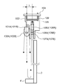
図1Aは本発明の実施形態1の遮光方式の座標入力装置の構成を示す図である。
<
FIG. 1A is a diagram illustrating a configuration of a light-shielding coordinate input device according to a first embodiment of the present invention.
図1Aにおいて、1L、1Rは投光部および受光部を有するセンサユニットであり、実施形態1の場合、図示の如く座標入力面であるところの座標入力有効領域3のX軸に平行に、かつY軸に対称な位置に、所定距離離れて配置されている。センサユニット1L及び1Rは、制御・演算ユニット2に接続され、制御信号を制御・演算ユニット2から受信すると共に、検出した信号を制御・演算ユニット2に送信する。
In FIG. 1A,
4は入射光を到来方向に反射する再帰反射面を有する再帰反射部であり、座標入力有効領域3の外側3辺に図示が如く配置され、左右それぞれのセンサユニット1L及び1Rから略90°範囲に投光された光を、センサユニット1L及び1Rに向けて再帰反射する。
尚、再帰反射部4は、ミクロ的に見て三次元的な構造を有し、現在では、主にビーズタイプの再帰反射テープ、或いはコーナキューブを機械加工等により規則正しく配列することで再帰現象を起こす再帰反射テープが知られている。
The
再帰反射部4で再帰反射された光は、センサユニット1L及び1Rによって1次元的に検出され、その光強度分布が制御・演算ユニット2に送信される。
The light retroreflected by the
座標入力有効領域3は、PDPやリアプロジェクタ、LCDパネルなどの表示装置の表示画面で構成することで、インタラクティブな入力装置として、利用可能となっている。
The coordinate input
このような構成において、座標入力有効領域3に指や指示具等の指示手段による入力指示がなされると、センサユニット1L及び1Rの投光部から投光された光が遮られ(遮光部分)、センサユニット1L及び1Rの受光部ではその遮光部分の光(再帰反射による反射光)を検出できないので、その結果、どの方向からの光が検出できなかったかを判別することが可能となる。
In such a configuration, when an input instruction is given to the coordinate input
そこで、制御・演算ユニット2は、左右のセンサユニット1L及び1Rが検出する光強度変化から、指示具によって入力指示された部分の複数の遮光範囲を検出し、その遮光範囲の端部情報から、センサユニット1L及び1Rそれぞれに対する遮光範囲の端部の方向(角度)をそれぞれ算出する。また、指示具が信号発信部を有する場合には、その指示具からのペン信号をペン信号受信部5が受信する。
Therefore, the control /
そして、検出された遮光範囲の数に基づいて、座標算出に用いる遮光範囲から得られるデータを決定し、それぞれ算出された方向(角度(図1Aでは、θL及びθR))、及びセンサユニット1L及び1R間の距離情報等から、座標入力有効領域3上の指示具の遮光位置を幾何学的に算出し、表示装置に接続されているホストコンピュータ等の外部端末に、インタフェース7(例えば、USB、IEEE1394等)を経由してその座標値を出力する。
Then, based on the number of detected light-shielding ranges, data obtained from the light-shielding ranges used for coordinate calculation is determined, the calculated directions (angles (θL and θR in FIG. 1A)),
このようにして、指示具によって、画面上に線を描画したり、表示装置に表示されるアイコンを操作する等の外部端末の操作が可能になる。 In this way, the operation of the external terminal such as drawing a line on the screen or operating an icon displayed on the display device can be performed by the pointing tool.
特に、本発明では、センサユニットによって検出される遮光範囲(影)を含む光強度分布と、基準となる入力がない状態(遮光なし状態)の時の基準光強度分布とを比較する。この比較においては、処理対象の光強度分布と基準光強度分布を用いて得られる相対光強度分布に対して、その相対光強度分布中のどの部分がどれだけの比率で遮光されたかを判定するための第一閾値と、その第一閾値より遮光の度合いが大きい部分を判定するための第二閾値を設ける(図1B参照)。 Particularly, in the present invention, the light intensity distribution including the light shielding range (shadow) detected by the sensor unit is compared with the reference light intensity distribution when there is no reference input (no light shielding state). In this comparison, with respect to the relative light intensity distribution obtained by using the light intensity distribution to be processed and the reference light intensity distribution, it is determined which part of the relative light intensity distribution is shielded at what ratio. And a second threshold for determining a portion having a greater degree of light shielding than the first threshold (see FIG. 1B).
そして、これらの第一及び第二閾値と、相対光強度分布から得られる遮光(入力)によって得られる影の強度(遮光による光強度の低下率、あるいは深さ)を比較することにより、複数の入力を並行して行った場合にも、それらの入力を誤検出することなく、精度良く座標を算出する。 Then, by comparing the first and second threshold values with the intensity of the shadow obtained by the light shielding (input) obtained from the relative light intensity distribution (the reduction rate or depth of the light intensity due to the light shielding), a plurality of Even when inputs are performed in parallel, coordinates are accurately calculated without erroneous detection of those inputs.
<課題の説明>
ここで、本発明における、課題を再度、図を用いて詳しく説明する。
<Explanation of issues>
Here, the problem in the present invention will be described again in detail with reference to the drawings.
図2は本発明における課題を説明するための図である。 FIG. 2 is a diagram for explaining the problem in the present invention.
従来の構成では、上述の影の強度を判定するための閾値は単一の閾値を用いて構成されている。 In the conventional configuration, the threshold for determining the above-described shadow intensity is configured using a single threshold.
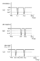
例えば、図1AのP点において、座標入力動作を実行すると、その入力状態に応じて、図2(a)や図2(b)に示すような相対光強度分布が得られる。この場合、図2(a)や図2(b)では、θL、θRの位置にP点での入力によって影が生成される。 For example, when a coordinate input operation is executed at point P in FIG. 1A, a relative light intensity distribution as shown in FIGS. 2A and 2B is obtained according to the input state. In this case, in FIGS. 2A and 2B, a shadow is generated at the positions of θL and θR by the input at the point P.
ここで、図2(a)は、指示具による座標入力を行っている状態における、センサユニット1Lから得られる相対光強度分布である。また、図2(b)は、座標入力有効領域に対し、指示具が入る際の瞬間、あるいは出る際の瞬間の状態における、センサユニット1Rから得られる相対光強度分布である。
Here, FIG. 2A is a relative light intensity distribution obtained from the
図2(a)と図2(b)を比較して明らかなように、1回の座標入力動作においても、その検出タイミングによっては、相対光強度分布中の遮光によって形成される影(遮光範囲)には大きな偏差がある。そして、この偏差は、入力位置、センサユニット1L及び1Rの光学特性、指示具の太さ等の要因で決まってくるものである。
As is clear from comparison between FIG. 2A and FIG. 2B, even in one coordinate input operation, depending on the detection timing, a shadow (light shielding range) formed by light shielding in the relative light intensity distribution. ) Has a large deviation. This deviation is determined by factors such as the input position, the optical characteristics of the
特に、P点の位置が、センサユニット1Lから近く、センサユニット1Rから遠い場合には、センサユニット1Lで検出する相対光強度分布における影は、幅、深さともに大きいものとなる。一方、センサユニット1Rで検出する相対光強度分布における影は、幅、深さともに小さいものとなる。
In particular, when the position of the point P is close to the
ここで、例えば、図2(a)に示すように、影の有無を判定する閾値を、thsh0(例えば、最大相対光強度100%とする場合の50%に相当する相対光強度)とすると、センサユニット1Lでは、
dpthL > thsh0
を満足するとき、センサユニット1Lでは、P点での指示入力に対する影は検出される。
Here, for example, as shown in FIG. 2A, if the threshold for determining the presence or absence of a shadow is thsh0 (for example, relative light intensity corresponding to 50% when the maximum relative light intensity is 100%), In the
dpthL> thsh0
Is satisfied, the
これに対し、センサユニット1Rでは、
dpthR < thsh0
を満足するとき、センサユニット1Rでは、P点での指示入力に対する影は検出されない。
On the other hand, in the
dpthR <thsh0
When satisfying the above, the
その結果、P点の位置座標は算出できない。 As a result, the position coordinates of point P cannot be calculated.
また、このような状況を回避するために、thsh0の値(例えば、最大相対光強度100%とする場合の30%に相当する相対光強度)を大きく設定したとしても、図2(b)に示すように、指示具が座標入力有効領域3に入る際の瞬間、あるいは出る際の瞬間のような、各センサユニットで検出される影が小さいときにおいては、
dpth’R< thsh0
となる場合が必ず発生する。つまり、センサユニット1Lにおいてのみ影が検出されて、センサユニット1Rにおいては影が検出されないことがある。従って、このような場合でも、P点の位置座標は算出できない。
In order to avoid such a situation, even if the value of thsh0 (for example, the relative light intensity corresponding to 30% when the maximum relative light intensity is 100%) is set large, FIG. As shown, when the shadow detected by each sensor unit is small, such as the moment when the pointing device enters the coordinate input
dpth'R <thsh0
There will always be a case. That is, a shadow may be detected only in the
このように、単一の座標入力動作(以下、単一入力とも略称する)においては、各センサユニットで検出されるべき影が各センサユニットと指示具の入力位置間の距離の違い等に起因して、一方のセンサユニットで検出されない場合が、指示具が座標入力有効領域への入る際、あるいは出る際において存在する。この場合、座標算出を実行することができない。 Thus, in a single coordinate input operation (hereinafter also abbreviated as “single input”), the shadow to be detected by each sensor unit is caused by a difference in the distance between the input positions of each sensor unit and the indicator. Thus, there is a case where the indicator is not detected by one of the sensor units when the pointing tool enters or exits the coordinate input effective area. In this case, coordinate calculation cannot be executed.
この事実は、特に、同時に複数の入力を許容する座標入力装置において、大きな問題となる。以下、この問題について図3を用いて説明する。尚、図3以降で説明する図面の内は、図1Aに準ずる図面は、図1Aで示す各種構成要素の一部を省略している。 This fact becomes a big problem particularly in a coordinate input device that allows a plurality of inputs at the same time. Hereinafter, this problem will be described with reference to FIG. 3 and the subsequent drawings, some of the various components shown in FIG. 1A are omitted from the drawings corresponding to FIG. 1A.
図3では、点Pa(例えば、図3のP12)と点Pb(例えば、図3のP21)に複数の入力を行った場合を示している。 FIG. 3 shows a case where a plurality of inputs are made to point Pa (for example, P12 in FIG. 3) and point Pb (for example, P21 in FIG. 3).
この場合、各センサユニットでは、図4に示すように、センサユニット1Lでは、θL1及びθL2の位置に影が検出され、センサユニット1Rでは、θR1及びθR2の位置に影が検出される。
In this case, in each sensor unit, as shown in FIG. 4, the
そして、これらの2組の角度データ(θL1及びθL2、θR1及びθR2)に基づいて、4つの座標候補点P11、P12、P21、P22が算出される。そして、これらの座標候補点の中から、虚実判定することにより、例えば、P11、P22は虚像であり、P12、P21が実像であることが判別され、座標入力点を決定することができる。 Then, based on these two sets of angle data (θL1 and θL2, θR1 and θR2), four coordinate candidate points P11, P12, P21, and P22 are calculated. From these coordinate candidate points, by determining the true or false, for example, it is determined that P11 and P22 are virtual images, and P12 and P21 are real images, and the coordinate input points can be determined.
このとき、上述したように、例えば、座標入力位置等の影響により、座標入力位置に近い側のセンサユニットで検出される影が、幅、深さともに大きく、座標入力位置に遠い側のセンサユニットで検出される影が、幅、深さともに小さくなって、何れかの影を検出できなかった場合、誤った座標候補点を検出してしまう。 At this time, as described above, for example, the shadow detected by the sensor unit closer to the coordinate input position due to the influence of the coordinate input position or the like is large in both width and depth, and the sensor unit on the side far from the coordinate input position. When the shadow detected in (2) becomes smaller in both width and depth, and any of the shadows cannot be detected, an erroneous coordinate candidate point is detected.
このような場合の一例について、以下に説明する。 An example of such a case will be described below.
図5及び図6はθL2、θR2を示す影が閾値thsh0を越えないために、正確な座標検出ができない場合の複数の入力例を示している。 5 and 6 show a plurality of input examples in the case where accurate coordinates cannot be detected because the shadows indicating θL2 and θR2 do not exceed the threshold thsh0.
この場合、各センサユニットでは、図5及び図6に示すように、破線の方向の影(即ち、P12、P21、P22)を検出できない。そのため、実際には、Pa(例えば、図5のP12)、Pb(例えば、図5のP21)の位置に複数の入力を行っているにも関わらず、P11の位置にのみ1つの入力がなされていると誤検出する。 In this case, as shown in FIGS. 5 and 6, each sensor unit cannot detect a shadow in the direction of the broken line (that is, P12, P21, P22). Therefore, in practice, one input is made only at the position of P11 even though a plurality of inputs are made at the positions of Pa (for example, P12 in FIG. 5) and Pb (for example, P21 in FIG. 5). False positive.
更に、別の一例について説明する。 Furthermore, another example will be described.
図7及び図8はθR2のみ閾値thsh0を越えないために、正確な座標検出ができない場合の複数の入力例を示している。 7 and 8 show a plurality of input examples when accurate coordinate detection cannot be performed because only θR2 does not exceed the threshold value thsh0.
この場合、センサユニット1Rでは、図7及び図8に示すように、破線の方向の影(即ち、P12、P12)を検出できない。そのため、実際には、Pa(例えば、図5のP12)、Pb(例えば、図5のP21)の位置に複数の入力を行っているにも関わらず、あたかも2つの入力点がP11、P21に存在し、それらが、センサユニット1Rから見て、重なっている状態であると誤検出する。
In this case, as shown in FIGS. 7 and 8, the
このように、同時の複数の座標入力動作(以下、複数入力とも略称する)においても、単一入力と同様に、各センサユニットで検出されるべき影が各センサユニットと指示具の入力位置間の距離の違い等に起因して、一方のセンサユニットで検出されない場合が、指示具が座標入力有効領域への入る際、あるいは出る際において存在する。この場合、座標算出を実行することができない。また、複数入力を許容する場合には、座標算出が不可能になるどころか、誤った座標ないし座標候補を算出してしまう。 As described above, even in a plurality of simultaneous coordinate input operations (hereinafter also abbreviated as “multiple inputs”), as in the case of a single input, the shadow to be detected by each sensor unit is between the input positions of each sensor unit and the indicator. When the pointing device enters or exits the coordinate input effective area, it may not be detected by one of the sensor units due to a difference in the distance between them. In this case, coordinate calculation cannot be executed. In addition, if multiple inputs are allowed, an incorrect coordinate or coordinate candidate is calculated, rather than calculating the coordinate.
そこで、本発明は、これらの問題を解決する構成を提案するものであり、特に、本発明においては、相対光強度分布から遮光による影の存在を検知するための閾値を2つ設定する。また、この2つの閾値は、センサユニットの光学特性から想定される影の強度(相対光強度分布における谷の深さ)の最大比率に基づいて設定する。 Therefore, the present invention proposes a configuration that solves these problems. In particular, in the present invention, two thresholds for detecting the presence of shadows due to light shielding are set from the relative light intensity distribution. The two threshold values are set based on the maximum ratio of the shadow intensity (the depth of the valley in the relative light intensity distribution) assumed from the optical characteristics of the sensor unit.
ここで、想定される影の強度の最大値をdpth_max、最大値dpth_minとすると、影の強度の最大比率Mは
M=dpth_max/dpth_min (式1_1)
となる。そして、このときに、
thsh1 / thsh2 > M (式1_2)
を満足する閾値を設定する。これら2つの閾値を、相対光強度分布に適用すれば、大きい方の影が第二閾値(thsh2)を越えているとき、必ず小さい方の影も第一閾値(thsh1)を越えることになる。つまり、大きい方の影の存在を第二閾値(thsh2)で判定し、小さいほうの影を第一閾値(thsh1)で判定する構成にする。これにより、上述のような、大きい方の影が検知されているにもかかわらず、小さい方の影が検知できず、誤った座標を算出してしまうことを回避できる。
Here, assuming that the maximum value of the assumed shadow intensity is dpth_max and the maximum value dpth_min, the maximum ratio M of shadow intensity is M = dpth_max / dpth_min (Formula 1_1)
It becomes. And at this time,
thsh1 / thsh2> M (Formula 1_2)
A threshold value that satisfies the above is set. If these two thresholds are applied to the relative light intensity distribution, when the larger shadow exceeds the second threshold (thsh2), the smaller shadow necessarily exceeds the first threshold (thsh1). That is, the configuration is such that the presence of the larger shadow is determined by the second threshold (thsh2), and the smaller shadow is determined by the first threshold (thsh1). As a result, it is possible to avoid calculating the wrong coordinates because the smaller shadow cannot be detected even though the larger shadow is detected as described above.
このような構成によれば、単一入力の場合では、指示具の座標入力有効領域への入る際と出る際で座標計算ができなくなることを回避できる。また、複数入力の場合では、誤った座標候補を認識してしまうことにより、影の重複の有無を誤認識し、その結果として、誤った座標を算出してしまう問題を回避できる。 According to such a configuration, in the case of a single input, it can be avoided that coordinate calculation cannot be performed when the pointing tool enters and exits the coordinate input effective area. Further, in the case of a plurality of inputs, by recognizing an incorrect coordinate candidate, it is possible to avoid the problem of erroneously recognizing the presence or absence of overlapping shadows and, as a result, calculating an incorrect coordinate.
このように、本発明によって得られる効果は非常に大きく、この分野の座標入力装置においては必須のものということができる。 Thus, the effect obtained by the present invention is very large, and it can be said that it is essential in the coordinate input device in this field.
次に、本発明の実施形態1における構成について説明する。
Next, the structure in
図9〜図11は、図3に示す複数入力を行った場合の、2つのセンサユニット1L及び1Rから得られる相対光強度分布中の影の数と、設定する閾値との関係を全てのパターン(順番のみ入れ替わったものについては省略している)を模式的に示している。
9 to 11 show the relationship between the number of shadows in the relative light intensity distribution obtained from the two
尚、図9〜図11では、相対光強度分布中の影をs1,s2,s3,s4で示している。 In addition, in FIGS. 9-11, the shadow in relative light intensity distribution is shown by s1, s2, s3, s4.
この図9〜図11の各図において、左側の図は、第一閾値thsh1を越える影の数が多い方のセンサユニットで検出された影の構成を示している。また、右側の図は、第一閾値thsh1を越える影の数が少ない方のセンサユニットで検出された影の構成を示している。 In each of FIGS. 9 to 11, the diagrams on the left side show the configuration of shadows detected by the sensor unit having the larger number of shadows exceeding the first threshold thsh1. Further, the right diagram shows the configuration of the shadow detected by the sensor unit with the smaller number of shadows exceeding the first threshold thsh1.
便宜的に、センサユニット1Lで検出される影の数の方が多いものとして説明する。また、図9〜図11の各図において、影の位置には意味は無く、影の数と影の強度(深さ)と閾値(thsh1、thsh2)との関係のみ意味をなすものである。
For convenience, the description will be made assuming that the number of shadows detected by the
図3に示す構成に対する複数入力においては、例えば、2つのセンサユニット1L及び1Rによって、有効な2組の座標候補点を確定し、その中から最終的な座標入力点を確定する。あるいは、第3のセンサユニットを構成して、その第3のセンサユニットから得られる情報と、1組の座標候補点で最終的な座標入力点を確定する構成としても良い。
In a plurality of inputs to the configuration shown in FIG. 3, for example, two effective coordinate candidate points are determined by two
実施形態1では、複数入力を想定しているので、単一入力、複数入力、複数入力に伴う影の重複の判定を、検出される影の状態、即ち、影が2つの閾値を越えているか否かによって、確証を持って実行する。これにより、誤りのない確証のある座標候補点のみを確定し、誤った座標算出を防止することができる。 In the first embodiment, since multiple inputs are assumed, it is determined whether there is a single input, multiple inputs, or overlap of shadows associated with multiple inputs, the state of the detected shadow, that is, whether the shadow exceeds two thresholds. Execute with confirmation, depending on whether or not. Thereby, it is possible to determine only coordinate candidate points with a certainty without error and prevent erroneous coordinate calculation.
以下、図9〜図11について説明する。 Hereinafter, FIGS. 9 to 11 will be described.
[[A分類(図9)]]
図9に示すA分類は、センサユニット1L及び1Rとも、少なくとも第一閾値thsh1を越える影の数が1個ずつの場合を示している。
[[A classification (Fig. 9)]]
The A classification shown in FIG. 9 shows a case where the number of shadows exceeding at least the first threshold thsh1 is one for each of the
[図9(a)の場合]
センサユニット1L及び1Rで検出される影がともに第二閾値thsh2を越えているので、同一の入力に伴うセンサユニット1Rで検出される影も、少なくとも第一閾値thsh1を超えているはずである。ここでは、センサユニット1Rで、第一閾値thsh1を越えているのはs3のみである。
[In the case of FIG. 9A]
Since the shadows detected by the
センサユニット1R側の影の内、センサユニット1L側の影s1に対応する影は、影s3、もしくは影s3とほぼ同じ位置で重複している影S4(破線)のどちらかである。
Of the shadows on the
一方、影s3においても、同様の議論ができる。即ち、センサユニット1L側の影の内、影s3に対応する影は、影s1、もしくは影s1とほぼ同じ位置で重複している影s2(破線)のどちらかである。
On the other hand, the same argument can be made for the shadow s3. That is, among the shadows of the
ここで、センサユニット1L及び1Rとも、影が重複しているということは、同じ位置を指示している入力、即ち、単一入力、あるいは単一入力とみなして良い状態である。
Here, in both the
これにより、影s1と影s3は、影として対応している、即ち、(s1,s3)の1入力と判定できる。 Thereby, it can be determined that the shadow s1 and the shadow s3 correspond as shadows, that is, one input of (s1, s3).
[図9(b)の場合]
センサユニット1L側の影s1に対応する、センサユニット1R側の影は、影s3あるいは影s3と重複する影s4(破線)である。一方、センサユニット1R側の影s3に対応する、センサユニット1L側の影は、影s3が第二閾値thsh1を越えていないため、影s1あるいは影s1と重複している影s2(破線)、あるいは別の位置にあって未だ検出されていない影s2’(第一閾値thsh1すらを越えていない)のいずれであるかが不明である。
[In the case of FIG. 9B]
The shadow on the
この場合、(s1,s3)で定義される1つの入力が少なくとも存在することは確定される。 In this case, it is determined that at least one input defined by (s1, s3) exists.
但し、2つ目の入力が存在することは必ずしも否定できない。即ち、(s2,s3)、または(s2,s4)で定義されるもう1つの入力が存在する可能性がある。 However, it cannot be denied that the second input exists. That is, there may be another input defined by (s2, s3) or (s2, s4).
[図9(c)の場合]
これは、影s1が影s3に対応しない場合である。この場合、(s1,s3)が存在する可能性が大であるが、(s1,s4)及び(s2,s3)で定義される2つの入力が不完全に(即ち、第2二閾値thsh2を越えることなく)検出されている場合もある。そのため、何れの入力も確定できない。
[In the case of FIG. 9C]
This is a case where the shadow s1 does not correspond to the shadow s3. In this case, there is a high possibility that (s1, s3) exists, but the two inputs defined by (s1, s4) and (s2, s3) are incomplete (ie, the second second threshold thsh2 is set). It may be detected (without exceeding). Therefore, no input can be determined.
[[B分類(図10)]]
図10に示すB分類は、第一閾値thsh1を超える影の数が、一方のセンサユニット(ここでは、センサユニット1L側として説明する)で2個、他方のセンサユニットで1個の場合を示している。
[[B classification (FIG. 10)]]
The B classification shown in FIG. 10 shows a case where the number of shadows exceeding the first threshold thsh1 is two for one sensor unit (here, described as the
[図10(a)及び(b)の場合]
センサユニット1L側の影s1及び影s2は、ともに第二閾値thsh2を越えている。このため、これらに対応するセンサユニット1R側の影も必ず第一閾値thsh1を越えているはずである。ここで、センサユニット1R側で、第一閾値thsh1を越えているのは影s3のみである。尚、影s4は影s3と重複しているので、ここでは、影s3と同一視する。
[In the case of FIGS. 10A and 10B]
Both the shadow s1 and the shadow s2 on the
従って、影s1及び影s2に対応する、センサユニット1Rの影は、影s3の位置に少なくとも重なって存在するといえる。即ち、(s1,s3)、(s2,s3)の2つの入力があると確定できる。
Therefore, it can be said that the shadow of the
[図10(c)及び(d)の場合]
センサユニット1L側の影s1は、第二閾値thsh2を越えている。このため、これに対応するセンサユニット1R側の影は、少なくとも第一閾値thsh1を越えているはすである。ここで、センサユニット1R側で第一閾値thsh1を越えているのは、影s3のみである。従って、影s1に対応する影は、影s3あるいは影s3と重複している影s4である。
[FIGS. 10C and 10D]
The shadow s1 on the
一方、影s2は、第一閾値thsh1を超えているが第二閾値thsh2を越えてはいない。従って、これに対応するセンサユニット1R側の影は、必ずしも第一閾値thsh1を超えているとはいえず、影s3、あるいは影s3と重複している影s4とも言い切ることはできない。
On the other hand, the shadow s2 exceeds the first threshold thsh1, but does not exceed the second threshold thsh2. Accordingly, the corresponding shadow on the
従って、この場合、(s1,s3)の入力は存在すると確定できる。また、もう1つの入力が存在することも確かだが、それが(s2,s3)であるのか(s2,s4)であるのかは不明であり、確定できない(ここでは、影s4’が存在する可能性がある)。 Therefore, in this case, it can be determined that the input of (s1, s3) exists. It is also certain that there is another input, but it is unclear whether it is (s2, s3) or (s2, s4), and cannot be determined (here, a shadow s4 'may exist) Have sex).
[図10(e)及び(f)の場合]
センサユニット1R側の影s3は、第二閾値thsh2を超えている。このため、これに対応するセンサユニット1L側の影は、少なくとも第一閾値thsh1を超えているはずである。
[In the case of FIGS. 10E and 10F]
The shadow s3 on the
ところが、センサユニットL側で、第一閾値thsh1を超えている影は、影s1及び影s2の2つが存在し、いずれも第2二閾値thsh2を超えていない。そのため、これらに対応する影は、センサユニットR側の影s3、あるいは影s3に重複している影s4に対応するのか、別の位置にあって未だ検出されていない影s4’に対応するのかが判明しない。 However, there are two shadows s1 and s2 as shadows that exceed the first threshold thsh1 on the sensor unit L side, and none of them exceeds the second second threshold thsh2. Therefore, the shadow corresponding to these corresponds to the shadow s3 on the sensor unit R side, or the shadow s4 overlapping with the shadow s3, or corresponds to the shadow s4 ′ that is not yet detected at another position. Is not clear.
従って、この場合、2入力が存在することは確かであるだが、結果として確定できる入力(即ち、影の組み合わせ)は存在しない。 Therefore, in this case, it is certain that there are two inputs, but there is no input (that is, a combination of shadows) that can be determined as a result.
[[C分類](図11)]
図11に示すC分類は、センサユニット1L及び1Rとも、2つの影の位置が特定できている。ここで、3番目の入力は禁止されていて入力は少なくも2入力であることは確かである。従って、全ての影の位置は特定でき、別の位置にあって未だ検出されていない影はないといえる。
[[C classification] (FIG. 11)]
In the C classification shown in FIG. 11, the positions of two shadows can be specified for both the
従って、この場合、各影が第二閾値thsh2を超えているいないに関わらず、図11(a)〜(f)のいずれの場合も、2つの実入力の座標位置は特定できないが、少なくとも2つの実入力点を含む4つの座標候補点を確定することができる。 Accordingly, in this case, the coordinate positions of the two actual inputs cannot be specified in any of the cases of FIGS. 11A to 11F, regardless of whether each shadow exceeds the second threshold thsh2. Four coordinate candidate points including one actual input point can be determined.
以上のように、実施形態1では、図9〜図11に示す分類に基づいて、入力座標の確定、または4座標候補点の確定、または2つの重複点の確定を実現することができる。 As described above, in the first embodiment, input coordinates, four coordinate candidate points, or two overlapping points can be determined based on the classifications illustrated in FIGS. 9 to 11.
以上、図9〜図11において、センサユニット1L及び1Rで検出される影数の検出状態に基づく、座標候補点の確定状態の組をまとめると、以下のように定義できる。ここで、影数の組み合わせを、[X−Y](X=1、2、Y=1、2)と表現する。
As described above, in FIG. 9 to FIG. 11, a set of coordinate candidate point determination states based on the detection state of the number of shadows detected by the
確定状態(1)([1−1]a):単一入力点の確定
確定状態(2)([1−1]b):2入力点のうちの1入力点の確定
確定状態(3)([2−1]) :2入力点が一方のセンサユニット(片方のセンサユニット)から見て重複していることの確定
確定状態(4)([2−2]) :2つの実入力点を含む4つの座標候補点の確定
確定状態(5)([0−0]) :入力点及び座標候補点の確定なし
尚、ここで表現する確定状態(1)〜(5)は、あくまでもセンサユニット1L及び1Rで検出される単純な影の数ではなく、上記の2つの閾値との関係に基づいて、以下に示す座標候補点確定処理によって、入力点あるいは座標候補点の存在の確実性があると判定された確定状態を示すための影の数である。そのため、場合によっては、実際に検知される影の数とは異なり、それより少ない場合がある。
Determining state (1) ([1-1] a): Determining a single input point Determining state (2) ([1-1] b): Determining one input point out of two input points Determining state (3) ([2-1]): Confirmation that two input points overlap when viewed from one sensor unit (one sensor unit) Confirmation state (4) ([2-2]): Two actual input points Confirmation of four coordinate candidate points including “Confirmed state (5)” ([0-0]): No confirmation of input point and coordinate candidate point Note that the confirmed states (1) to (5) expressed here are only sensors. Based on the relationship between the above two thresholds rather than the simple number of shadows detected by the
以上が、実施形態1における入力点あるいは座標候補点の確定原理である。また、この確定原理に対し、虚実判定を組み合わせることで、複数入力に対応する遮光入力方式の座標入力装置を構成することができる。 The above is the principle of determining input points or coordinate candidate points in the first embodiment. Further, by combining this determination principle with true / false determination, a light-shielding input type coordinate input device corresponding to a plurality of inputs can be configured.
以下、実施形態1の座標候補点確定処理について、図12を用いて説明する。 Hereinafter, the coordinate candidate point determination process according to the first embodiment will be described with reference to FIG.
図12は本発明の実施形態1の座標候補点確定処理を示すフローチャートである。 FIG. 12 is a flowchart showing coordinate candidate point determination processing according to the first embodiment of the present invention.
まず、ステップS1で、センサユニット1L及び1Rで検出される相対光強度分布から、第1閾値(thsh1)を越える影の数を判定する。そして、この判定結果に基づいて、各処理に分岐する。
First, in step S1, the number of shadows exceeding the first threshold (thsh1) is determined from the relative light intensity distribution detected by the
ステップS1で、影数の組み合わせが[1−1]である場合、ステップS2に進み、処理対象の影の内、第二閾値(thsh2)を越える影数に1が含まれるか否かを判定する。1が含まれる場合(ステップS2でYES)、ステップS3に進み、確定状態(1)であると判定する。一方、1が含まれない場合(ステップS2でNO)、ステップS4に進み、確定状態(5)であると判定する。 If the combination of the number of shadows is [1-1] in step S1, the process proceeds to step S2, and it is determined whether or not 1 is included in the number of shadows exceeding the second threshold (thsh2) among the shadows to be processed. To do. If 1 is included (YES in step S2), the process proceeds to step S3, and it is determined that the state is the final state (1). On the other hand, when 1 is not included (NO in step S2), the process proceeds to step S4, and it is determined that the state is the finalized state (5).
また、ステップS1で、影数の組み合わせが[2−1]である場合、ステップS7に進み、処理対象の影の内、第二閾値(thsh2)を越える影数の内、一方のセンサユニット甲(センサユニット1Lあるいは1R)(この場合、他方は、センサユニット乙(センサユニット1Rあるいは1L)となる)側の影数に2が含まれるか否かを判定する。2が含まれる場合、ステップS8に進み、確定状態(3)であると判定する。1が含まれる場合、ステップS9に進み、確定状態(2)であると判定する。0が含まれる場合、ステップS10に進み、確定状態(5)であると判定する。
If the combination of shadow numbers is [2-1] in step S1, the process proceeds to step S7, and one of the sensor unit blocks in the shadow number exceeding the second threshold (thsh2) among the shadows to be processed. It is determined whether or not 2 is included in the number of shadows on the side of (
また、ステップS1で、影数の組み合わせが[2−2]である場合、ステップS5に進み、確定状態(4)であると判定する。 If the combination of the number of shadows is [2-2] in step S1, the process proceeds to step S5 and is determined to be in the finalized state (4).
また、ステップS1で、影数の組み合わせが[2−0]あるいは[1−0]である場合、ステップS6に進み、確定状態(5)であると判定する。 If the combination of the number of shadows is [2-0] or [1-0] in step S1, the process proceeds to step S6 and it is determined that the state is the finalized state (5).
そして、これらの確定状態に基づいて、各確定状態に適した座標算出処理を実行することで、複数入力に係る座標算出を精度良く実行することができる。尚、この座標算出処理の具体例については、実施形態2で説明する。 Then, based on these finalized states, coordinate calculation processing suitable for each finalized state is executed, so that coordinate calculation related to a plurality of inputs can be performed with high accuracy. A specific example of this coordinate calculation process will be described in the second embodiment.
以上説明したように、実施形態1の構成による、遮光方式の座標入力装置では、座標入力有効領域に対する入力を観測する複数のセンサユニット中の任意のセンサユニットの組において、入力によって検出する影の数が多い一方のセンサユニットの影の強度と影の数から、入力の実在を確定できる入力点の数を判定するとともに、一方のセンサユニット(センサユニット甲)で検知される影の数と、他方のセンサユニット(センサユニット乙)で検出される影の数を比較して、影の重複の有無を判定する。 As described above, in the light-shielding coordinate input device according to the configuration of the first embodiment, a shadow detected by input in an arbitrary set of sensor units among a plurality of sensor units that observe input to the coordinate input effective area is input. While determining the number of input points that can determine the existence of the input from the shadow intensity and the number of shadows of one sensor unit with a large number, the number of shadows detected by one sensor unit (sensor unit A), The number of shadows detected by the other sensor unit (sensor unit B) is compared to determine whether there is a shadow overlap.
ここで、センサユニットから得られる相対光強度分布に対し、センサユニット乙で影の存在を判定するための閾値を第1閾値、センサユニット甲で影の存在を判定するための閾値を第2閾値とすると、第一閾値に対して第二閾値は、より強度(相対光強度分布で遮光されている度合)の高いレベルに設定する。 Here, with respect to the relative light intensity distribution obtained from the sensor unit, a threshold value for determining the presence of a shadow at the sensor unit B is a first threshold value, and a threshold value for determining the presence of a shadow at the sensor unit A is a second threshold value. Then, the second threshold value is set to a higher level than the first threshold value (the degree of light shielding by the relative light intensity distribution).
このように構成することで、例えば、センサユニット甲でN個の影を検出した場合、センサユニット乙からも、影が重複していない限り、影が検出されるはずである。そして、センサユニット乙で検出する影数が、センサユニット甲の影数と同数である場合は影の重複がなく、影数が少ない場合はその数分重複があると判定できる。 With this configuration, for example, when N shadows are detected by the sensor unit A, the shadows should be detected from the sensor unit B as long as the shadows do not overlap. Then, when the number of shadows detected by the sensor unit B is the same as the number of shadows of the sensor unit A, it can be determined that there is no overlap of shadows, and when the number of shadows is small, there are as many overlaps as there are.
ここで、両者が検出する影数がN個の場合は、N×N個の座標候補点を確定でき、また、センサユニット乙で検出する影数が1個の場合は、N個の座標候補点を確定できる、という判定が成立する。 Here, when the number of shadows detected by both is N, N × N coordinate candidate points can be determined, and when the number of shadows detected by the sensor unit B is 1, N coordinate candidates The determination that the point can be confirmed is established.
これを、N=2に適用すると、本発明は、以下の判定を実現することができる。 When this is applied to N = 2, the present invention can realize the following determination.
センサユニット甲において、第二閾値を越える影数が2個で、センサユニット乙において第一閾値を越える影数が2個である場合は、4個の座標候補点の存在を確定する。 If the sensor unit A has two shadows exceeding the second threshold and the sensor unit B has two shadows exceeding the first threshold, the existence of four coordinate candidate points is determined.
センサユニット甲において、第二閾値を越える影数が2個で、センサユニット乙において第一閾値を越える影数が1個である場合は、2個の座標入力点がセンサユニット乙から見て略直線状に並んでいる(重複している)と確定する。 When the number of shadows exceeding the second threshold is 2 on the sensor unit A and the number of shadows exceeding the first threshold is 1 on the sensor unit B, the two coordinate input points are omitted when viewed from the sensor unit B. It is confirmed that they are arranged in a straight line (overlapping).
センサユニット甲において、第二閾値を越える影数が1個で、センサユニット乙において第一閾値を越える影数が1個である場合は、1個の座標入力点が存在すると確定する。 When the number of shadows exceeding the second threshold is 1 in the sensor unit A and the number of shadows exceeding the first threshold is 1 in the sensor unit B, it is determined that one coordinate input point exists.
以上のような構成により、実施形態1では、異なったセンサユニット間において、同一の入力に伴って検出される影(遮光範囲)がレベルの差をもって検知されるような場合においても、座標入力有効領域における指示状態(上記の確定状態及び検出状態)を判定することで、単一入力では入力座標を検出しそこなうことを防止でき、複数入力では入力座標と異なる誤った座標を検出することを防止できる。
With the configuration described above, in
また、実施形態1の構成では、指示具が入力に伴って座標入力有効領域への入る際と出る際において発生する誤検出等の問題を回避でき、安定した座標入力を実現することができる。 Further, in the configuration of the first embodiment, it is possible to avoid problems such as false detections that occur when the pointing tool enters and exits the coordinate input effective area with input, and stable coordinate input can be realized.
<実施形態2>
図13は本発明の実施形態2の遮光方式の座標入力装置の構成を示す図である。
<
FIG. 13 is a diagram showing a configuration of a light shielding type coordinate input apparatus according to the second embodiment of the present invention.
図13に示す座標入力装置は、基本構成としては、図1Aの座標入力装置と変わらない。また、実施形態1では、センサユニット1L及び1Rの詳細構成については、特に説明しなかったが、これについては、実施形態2でまとめて説明する。
The basic configuration of the coordinate input device shown in FIG. 13 is the same as the coordinate input device of FIG. 1A. In the first embodiment, the detailed configuration of the
また、実施形態1のセンサユニット1L及び1Rが、内蔵する投光部および受光部それぞれ1組である場合を示しているのに対し、実施形態2の図13では、センサユニット1L及び1Rが、それぞれ2組構成している場合を示している。つまり、実施形態1では、1つのセンサユニット内に1つの光学ユニットを内蔵する単眼構成になっているのに対し、実施形態2では、1つのセンサユニット内に2つの光学ユニットを内蔵する複眼(二眼)構成になっている。
Moreover, while the
<センサユニット1の詳細説明>
次に、センサユニット1L及び1R内の構成について、図14を用いて説明する。尚、センサユニット1L及び1Rは、上述したように、大きく分けて投光部と受光部から構成される。
<Detailed description of
Next, the configuration in the
図14は本発明の実施形態2のセンサユニットの詳細構成を示す図である。 FIG. 14 is a diagram showing a detailed configuration of the sensor unit according to the second embodiment of the present invention.
図14において、101A及び101Bは、赤外光を発する赤外LEDであり、各々投光レンズ102A及び102Bによって、再帰反射部4に向けて略90°範囲に光を投光する。ここで、センサユニット1L及び1R中の投光部は、この赤外LED101A及び101Bと、投光レンズ102A及び102Bによって実現される。これにより、センサユニット1L及び1Rには、それぞれ2つの投光部が構成されることになる。
In FIG. 14, 101A and 101B are infrared LEDs that emit infrared light, and project light in a range of approximately 90 ° toward the
そして、投光部より投光された赤外光は、再帰反射部4により到来方向に再帰反射され、センサユニット1L及び1R中の受光部によって、その光を検出する。
Then, the infrared light projected from the light projecting unit is retroreflected in the arrival direction by the
受光部は、光線の視野を制限すると共に電気的なシールドをになうシールド部材105を設けた1次元のラインCCD104、集光光学系としての受光用レンズ(例えば、fθレンズ)106A及び106B、入射光の入射方向を概略制限する絞り108A及び108B、及び可視光等の余分な光(外乱光)の入射を防止する赤外フィルター107A及び107Bからなる。
The light receiving unit includes a one-
そして、再帰反射部4によって反射された光は、赤外フィルター107A及び107B、絞り108A及び108Bを抜けて受光用レンズ106A及び106Bによって、ラインCCD104の検出素子110面上に集光される。これにより、センサユニット1L及び1Rには、それぞれ2つの受光部が構成されることになる。
The light reflected by the
部材103及び部材109は、投光部及び受光部を構成する光学部品を配置するとともに、投光部で投光した光が直接受光部に入射することを防ぐ、あるいは外来光をカットするための上フード103、下フード109として機能する。
The
尚、実施形態2においては、絞り108A及び108Bは下フード109に一体で成型されているが、別部品であってもよいことはいうまでもなく、さらには、上フード103側に、絞り108A及び108Bと受光用レンズ106A及び106Bの位置決め部を設けることで、投光部の発光中心に対する受光部の位置決めを容易にする構成(つまり、上フード103のみで、すべての主要な光学部品が配置される構成)に実現することも可能である。
In the second embodiment, the
図15Aは、図14の状態のセンサユニット1L(1R)を組み上げた状態を、正面方向(座標入力面に対し垂直方向)から見た図である。図15Aに示すように、センサユニット1L(1R)中の2つの投光部は、所定距離d離れた状態で、それぞれの主光線方向が略平行となるように配置され、各々の投光レンズ102A及び102Bによって、それぞれ略90°範囲に光を投光するように構成している。
FIG. 15A is a view of the assembled state of the
図15Bは、図14Aの太矢印で示される部分の断面図であり、赤外LED101A(101B)からの光は、投光レンズ102A(102B)により、座標入力面に略平行に制限された光束として、主に再帰反射部4に対して光が投光されるように構成している。
FIG. 15B is a cross-sectional view of the portion indicated by the thick arrow in FIG. 14A. The light from the
一方、図15Cは、図15Aにおける赤外LED101A及び101B、投光レンズ102A及び102B、上フード103を取り除いた状態を、正面方向(座標入力面に対し垂直方向)から見た図である。
On the other hand, FIG. 15C is a view of the state in which the
ここで、実施形態2の場合、投光部と受光部は、座標入力面である座標入力有効領域3の垂直方向に対し重ねた配置構成(図15B参照)となっており、正面方向(座標入力面に対し垂直方向)から見て、投光部の発光中心と受光部の基準位置(つまり、角度を計測するための基準点位置に相当し、実施形態2にあっては絞り108A(108B)の位置であって、図中の光線が交差する点となる)が一致する構造となっている。
Here, in the case of
従って、前述した通り、2つの投光部は所定距離d離れた状態で、それぞれの主光線方向略平行となるように配置されているので、2つの受光部も同様に所定距離d離れた状態で、かつ各々の光軸(光学的な対称軸)が略平行となるように構成されている。 Therefore, as described above, since the two light projecting portions are arranged so as to be substantially parallel to each other in the principal ray direction with a predetermined distance d apart, the two light receiving portions are similarly separated by the predetermined distance d. And each optical axis (optical symmetry axis) is configured to be substantially parallel.
また、投光部により投光された座標入力面に略平行な光束であって、面内方向に略90°方向に投光されている光は、再帰反射部4により光の到来方向に再帰反射され、赤外フィルター107A(107B)、絞り108A(108B)、集光レンズ106A(106B)を経て、ラインCCD104の検出素子110面上に集光、結像することになる。
In addition, light that is approximately parallel to the coordinate input surface projected by the light projecting unit and is projected in a direction of approximately 90 ° in the in-plane direction is recursed in the light arrival direction by the
従って、ラインCCD104の出力信号は、反射光の入射角に応じた光強度分布を出力することになるので、ラインCCD104を構成する各画素の画素番号が角度情報を示すことになる。
Therefore, since the output signal of the
尚、図15Bに示す投光部と受光部の距離Lは、投光部から再帰反射部4までの距離に比べて十分に小さな値であり、距離Lを有していても十分な再帰反射光を受光部で検出することが可能な構成となっている。
Note that the distance L between the light projecting unit and the light receiving unit shown in FIG. 15B is sufficiently smaller than the distance from the light projecting unit to the
以上説明したように、センサユニット1L(1R)は、少なくとも2つの投光部と、各々の投光部で投光された光を各々検出する2つの受光部(実施形態2の場合、投光部が2組、受光部が2組)を有する構成である。
As described above, the
また、実施形態2にあっては、受光部の一部であるラインCCD104におけるライン状に配置された検出素子110の左側部分を第1受光部の集光領域、右側部分を第2受光部の集光領域とすることで、部品の共通化を図っているが、これに限定されるものでなく、各受光部毎に個別にラインCCDを設けてもよいことは言うまでもない。
In the second embodiment, the left part of the
<制御・演算ユニットの説明>
制御・演算ユニット2とセンサユニット1L及び1Rの間では、主に、受光部内のラインCCD104用のCCD制御信号、CCD用クロック信号と出力信号、及び投光部内の赤外LED101A及び101Bの駆動信号がやり取りされている。
<Description of control / arithmetic unit>
Between the control /
ここで、制御・演算ユニット2の詳細構成について、図16を用いて説明する。
Here, a detailed configuration of the control /
図16は本発明の実施形態2の制御・演算ユニットの詳細構成を示すブロック図である。 FIG. 16 is a block diagram showing a detailed configuration of a control / arithmetic unit according to the second embodiment of the present invention.
CCD制御信号は、ワンチップマイコン等で構成される演算制御回路(CPU)21から出力され、ラインCCD104のシャッタタイミングやデータの出力制御等が行われる。
The CCD control signal is output from an arithmetic control circuit (CPU) 21 constituted by a one-chip microcomputer or the like, and shutter timing of the
尚、この演算制御回路21は、クロック発生回路(CLK)22からのクロック信号に従って動作する。また、CCD用のクロック信号は、クロック発生回路(CLK)22からセンサユニット1L及び1Rに送信されると共に、各センサユニット内部のラインCCD104との同期をとって各種制御を行うために、演算制御回路21にも入力されている。
The
投光部の赤外LED101A及び101Bを駆動するためのLED駆動信号は、演算制御回路21からLED駆動回路(不図示)を介して、対応するセンサユニット1L及び1Rの投光部内の赤外LED101A及び101Bに供給されている。
The LED drive signal for driving the
センサユニット1L及び1Rそれぞれの受光部内のラインCCD104からの検出信号は、A/Dコンバータ23に入力され、演算制御回路21からの制御によって、デジタル値に変換される。この変換されたデジタル値は、メモリ132に記憶され、指示具の角度計算に用いられる。そして、この計算された角度から座標値が算出され、外部端末にシリアルインタフェース7(例えば、USB、IEEE1394、RS232Cインタフェース等)を介して出力される。
Detection signals from the
また、指示具としてペンを用いる場合、ペンからのペン信号を受信するペン信号受信部5からは、ペン信号を復調したデジタル信号が出力され、ペン信号検出回路としてのサブCPU24に入力され、ペン信号が解析された後、その解析結果が演算制御回路21に出力される。
When a pen is used as the pointing tool, a digital signal obtained by demodulating the pen signal is output from the pen
<センサユニット1の光学配置に関する詳細説明>
図17は本発明の実施形態2の座標入力装置の光学的な配置を説明するための説明図である。
<Detailed description regarding optical arrangement of
FIG. 17 is an explanatory diagram for explaining an optical arrangement of the coordinate input device according to the second embodiment of the present invention.
図17では、特に、左側センサユニット1Lの配置について説明する。尚、右側センサユニット1Rについては、図中Y軸について左側センサユニット1Lと対称な関係にある以外は、その特徴は同一なので、その説明は省略する。
In FIG. 17, in particular, the arrangement of the
先に述べた通り、センサユニット1Lには、2組の投光部と受光部(光学ユニットL1及びL2)を有し、両者の光軸(光学的な対称軸であって、光線151、及び光線161に相当)は、略平行にかつ所定距離d離れて配置されている。また、センサユニット1Lは、そのセンサ面が、座標入力有効領域3の一辺に対し、θsだけ傾いた方向となるように配置されている。
As described above, the
また、センサユニット1L中の一方の投光部の投光範囲(もしくは受光部の検出角度範囲)を光線152及び光線153、もう一方のそれを光線162及び光線163と定義する。
Further, the light projecting range (or the detection angle range of the light receiving unit) of one light projecting unit in the
尚、センサユニット1Rには、2組の投光部と受光部(光学ユニットR1及びR2)を有している。
The
光線152及び光線153、もしくは光線162及び光線163で定義される2組の光学ユニット(投光部及び受光部)の有効視野範囲は略90°であり、無論その範囲を、例えば、100°とすることも可能であるが、その有効視野範囲をより大きく設定、設計することは、例えば、光学ユニットを構成する光学部品(例えば、レンズ)の光学歪が大きくなり、安価に光学系を構成するという点で不利となる。
The effective visual field range of the two sets of optical units (the light projecting unit and the light receiving unit) defined by the
従って、各々の受光部で、投光された光を遮光する指示具の指示位置情報を得るためには、光線152及び光線163で定義される領域内に、座標入力有効領域を設定するのが好ましい形態である。そこで、座標入力有効領域を図示が如く領域171に設定すれば、センサユニット1L中の2組の受光部で、領域171中の指示具(遮光物体)の遮光位置を検出することが可能となる。
Accordingly, in order to obtain the pointing position information of the pointing tool that blocks the projected light at each light receiving unit, it is necessary to set the coordinate input effective area within the area defined by the
しかしながら、このように設定することで、例えば、各部品を内蔵した座標入力装置の筐体172と座標入力可能な領域171の関係で決まる筐体枠が大きくなり、操作可能な領域に比べ、座標入力装置全体の大きさが大きくなってしまうという課題が生じる。この課題を解決するためには、センサユニット1L(1R)の形状を小さくすることはいうまでも無く、さらには、光線151及び光線161で定義される2組の光学ユニット(投光部及び受光部)の所定距離dをより小さくするのが好ましい。
However, by setting in this way, for example, the housing frame determined by the relationship between the
実施形態2の座標入力装置に有っては、座標入力有効領域3と筐体172で決まる筐体枠を極力小さくするために、センサユニット1L(1R)中の一方の受光部は、座標入力有効領域3の全ての領域を有効視野に収めているが、もう一方の受光部は、図中領域173で定義される領域が有効視野外となる設定となっている。
In the coordinate input device according to the second embodiment, in order to make the casing frame determined by the coordinate input
さて、距離dは、指示具が座標入力有効領域3の左右端部ないし上端部にあるときに、指示具の方向から見た投影成分、即ち、d*cos(θL−θs)が、指示具の半径と略等しくなるよう構成されている。
The distance d is determined by the projection component viewed from the direction of the pointing tool when the pointing tool is at the left or right end or upper end of the coordinate input
このようにすることにより、図17において、背後の指示具が図中の光線151及び光線161の間の領域に完全に入り込んでしまうことがないように構成されている。
In this way, in FIG. 17, the pointing tool behind is configured not to completely enter the region between the
実施形態2は、例えば、図17中の光学ユニットL1、L1、R2、R1夫々から得られる光強度分布を取得する。そして、この光強度分布から夫々の光学ユニットで得られる、影の数、影の位置(角度)を算出し、センサユニット1Lを構成する光学ユニットL1あるいはL2と、センサユニット1Rを構成する光学ユニットR1あるいはR2から得られる4種類の組み合わせ、即ち、(L1,R1)、(L1,R2)、(L2,R1)及び(L2,R2)を順番に選択する。
In the second embodiment, for example, the light intensity distribution obtained from each of the optical units L1, L1, R2, and R1 in FIG. 17 is acquired. Then, the number of shadows and the shadow position (angle) obtained by each optical unit are calculated from the light intensity distribution, and the optical unit L1 or L2 constituting the
次に、それぞれの組み合わせにおいて、座標候補点の確定ないし座標候補点の重複状況の確定を行い、その中から、適切な光学ユニットの組み合わせを選定する。これにより、座標候補点の中から、実入力点を判定(所謂、虚実判定)し、最終的に、2つの入力座標を決定する。 Next, in each combination, the coordinate candidate points are determined or the overlapping situation of the coordinate candidate points is determined, and an appropriate combination of the optical units is selected from them. Thereby, an actual input point is determined from so-called coordinate candidate points (so-called true / false determination), and finally two input coordinates are determined.
以降、(L1,R1)、(L1,R2)、(L2,R1)及び(L2,R2)の4通りの組み合わせを、「LR光学ユニット組み合わせ」ないし「LR組み合わせ」と表現する。
次に、実施形態2における座標算出処理について、図18を用いて説明する。
Hereinafter, the four combinations (L1, R1), (L1, R2), (L2, R1), and (L2, R2) are expressed as “LR optical unit combinations” or “LR combinations”.
Next, the coordinate calculation process in
図18は本発明の実施形態2の座標入力装置が実行する座標算出処理を示すフローチャートである。 FIG. 18 is a flowchart showing coordinate calculation processing executed by the coordinate input device according to the second embodiment of the present invention.
まず、ステップS101で、光学ユニットL1、L2、R1及びR2の各光学ユニットにおける光強度分布データを取得する。次に、ステップS102で、取得した光強度分布データより、LR組み合わせに対する光強度分布データを順次選択して、選択した光強度分布データについて、実施形態1の図12の座標候補点確定処理を実行する(ステップS102〜ステップS109)。 First, in step S101, light intensity distribution data in each optical unit of the optical units L1, L2, R1, and R2 is acquired. Next, in step S102, the light intensity distribution data for the LR combination is sequentially selected from the acquired light intensity distribution data, and the coordinate candidate point determination process of FIG. 12 of the first embodiment is executed for the selected light intensity distribution data. (Steps S102 to S109).
次に、座標候補点確定処理の処理結果に基づいて、座標算出処理(ステップS110〜ステップS123)を実行する。 Next, a coordinate calculation process (steps S110 to S123) is executed based on the processing result of the coordinate candidate point determination process.
そして、各LR組み合わせに対する座標候補点確定処理によって、実施形態1で示したように、以下のいずれかの確定状態が得られる。 Then, by the coordinate candidate point determination process for each LR combination, as shown in the first embodiment, one of the following fixed states is obtained.
確定状態(1)([1−1]a):単一入力点の確定
確定状態(2)([1−1]b):2入力点のうちの1入力点の確定
確定状態(3)([2−1]) :2入力点が一方のセンサユニットから見て重複していることの確定
確定状態(4)([2−2]) :2つの実入力点を含む4つの座標候補点の確定
確定状態(5)([0−0]) :入力点及び座標候補点の確定なし
尚、実施形態1でも説明したように、ここで表現する確定状態(1)〜(5)は、あくまでもセンサユニット1L及び1Rで検出される単純な影の数ではなく、上記の2つの閾値との関係に基づいて、入力点あるいは座標候補点の存在の確実性があると判定された確定状態を示すための影の数である。そのため、場合によっては、実際に検知される影の数とは異なり、それより少ない場合がある。
Determining state (1) ([1-1] a): Determining a single input point Determining state (2) ([1-1] b): Determining one input point out of two input points Determining state (3) ([2-1]): Confirmation that two input points overlap when viewed from one sensor unit Confirmation state (4) ([2-2]): Four coordinate candidates including two actual input points Determination of points Determination state (5) ([0-0]): No determination of input points and coordinate candidate points As described in the first embodiment, the determination states (1) to (5) expressed here are However, it is not a simple number of shadows detected by the
そして、実施形態2では、各LR組み合わせそれぞれが、上記の確定状態(1)〜(5)のいずれであるかを判定して、その判定結果に基づいて、センサユニット1L及び1R内の各光学ユニットにおける影数の検出状態を決定する。
In the second embodiment, each LR combination is determined to be one of the above defined states (1) to (5), and based on the determination result, each optical unit in the
検出状態[1]:全てのLR組み合わせにおいて、[1−1]aまたは[1−1]bである。 Detection state [1]: [1-1] a or [1-1] b in all LR combinations.
検出状態[2]:[2−2]のLR組み合わせが2つ以上存在する。 Detection state [2]: There are two or more LR combinations of [2-2].
検出状態[3]:[2−2]のLR組み合わせと[2−1]のLR組み合わせが存在する。 Detection state [3]: There is an LR combination of [2-2] and an LR combination of [2-1].
検出状態[4]:[2−2]のLR組み合わせと[1−1]のLR組み合わせが存在する。 Detection state [4]: There is an LR combination of [2-2] and an LR combination of [1-1].
検出状態[5]:[2−1]のLR組み合わせが1つ以上存在する。 Detection state [5]: There is one or more LR combinations of [2-1].
そして、実施形態2では、各光学ユニットにおける影数の検出状態を判定し(ステップS110〜ステップS112、ステップS114〜ステップS116)、その判定した検出状態に応じて予め定義された座標算出方法[1]〜[5]で座標算出を行う(ステップS118〜ステップS122)。そして、座標算出結果を出力する(ステップS123)。一方、上記の検出状態のいずれも判定されない場合は、座標検出が不可能であると判定して、処理を終了する(ステップS113あるいはステップS117)。 In the second embodiment, the detection state of the number of shadows in each optical unit is determined (steps S110 to S112 and steps S114 to S116), and a coordinate calculation method [1 defined in advance according to the determined detection state [1. ] To [5] to calculate coordinates (steps S118 to S122). Then, the coordinate calculation result is output (step S123). On the other hand, if none of the above detection states is determined, it is determined that coordinate detection is impossible, and the process is terminated (step S113 or step S117).
尚、図18では、検出状態[1]〜[5]に関しては、上から順に優先的に検出状態を判定する。例えば、検出状態[3]と[4]を満足する場合は、優先的に検出状態[3]と判定する。 In FIG. 18, regarding the detection states [1] to [5], the detection states are determined in order from the top. For example, when the detection states [3] and [4] are satisfied, the detection state [3] is preferentially determined.
以下、座標算出方法[1]〜[5]それぞれの詳細について説明する。 Hereinafter, the details of each of the coordinate calculation methods [1] to [5] will be described.
座標算出方法[1](ステップS118:検出状態[1]の場合)
検出状態[1]の場合において、全てのLR組み合わせにおいて[1−1]aの場合は、単一入力がなされている場合である。また、全てのLR組み合わせにおいて[1−1]bの場合は、2入力がなされているが、一方の入力が正しく検出されていない場合である。
Coordinate calculation method [1] (in the case of step S118: detection state [1])
In the case of the detection state [1], the case of [1-1] a in all LR combinations is a case where a single input is made. In the case of [1-1] b in all LR combinations, two inputs are made, but one input is not correctly detected.
ここで、後者の場合は、主に、座標入力有効領域へ指示具が入る際、あるいは出る際の状態である。このような場合は、正しく検知されていない入力を無視することにより、誤った座標の算出を防止する。そこで、検出状態[1]の場合は、[1−1]aの場合でも[1−1]bの場合でも、単一入力として座標算出を実行する。 Here, the latter case is mainly a state when the pointing tool enters or exits the coordinate input effective area. In such a case, calculation of incorrect coordinates is prevented by ignoring inputs that are not correctly detected. Therefore, in the detection state [1], coordinate calculation is executed as a single input in both cases of [1-1] a and [1-1] b.
そして、この場合、どのLR組み合わせでも座標算出を実行することが可能であるが、例えば、(L1,R1)の光学ユニット組み合わせにおいて、後述する<座標算出処理(1)>によって座標算出を実行する。 In this case, the coordinate calculation can be executed by any LR combination. For example, in the optical unit combination (L1, R1), the coordinate calculation is executed by <coordinate calculation processing (1)> described later. .
座標算出方法[2](ステップS119:検出状態[2]の場合)
検出状態[2]とは、LR組み合わせ(L1,R1)、(L1,R2)、(L2,R1)及び(L2,R2)の中から2組以上[2−2]が存在する場合である。
Coordinate calculation method [2] (in the case of step S119: detection state [2])
The detection state [2] is a case where two or more pairs [2-2] are present from the LR combinations (L1, R1), (L1, R2), (L2, R1), and (L2, R2). .
この中から2つの組を選択し、其々から得られる4座標候補点を比較する。 Two sets are selected from these, and the four coordinate candidate points obtained from each are compared.
ここで、具体例として、(L1,R1)と(L2,R1)が[2−2]である場合を、図19及び図20を用いて説明する。 Here, as a specific example, the case where (L1, R1) and (L2, R1) are [2-2] will be described with reference to FIGS.
図19は(L1,R1)の組み合わせから、後述する<座標算出処理(1)>に基づいて、P11,P12,P21,P22を決定する。同様に、図20は(L2,R1)の組み合わせから、後述する<座標算出処理(2)>に基づいて、P’11,P’12,P’21,P’22を決定する。 In FIG. 19, P11, P12, P21, and P22 are determined from the combination of (L1, R1) based on <coordinate calculation processing (1)> described later. Similarly, in FIG. 20, P′11, P′12, P′21, and P′22 are determined from the combination of (L2, R1) based on <coordinate calculation processing (2)> described later.
ここで、それぞれのLR組み合わせから得られた4座標候補点の値を比較する。 Here, the values of the four coordinate candidate points obtained from the respective LR combinations are compared.
この中で、現実に入力された座標に基づく座標候補点は、どちらのLR組み合せにおいても原理的に同じ座標となる。一方、現実に入力された座標に基づかない座標(いわゆる、虚像としての座標候補点)は、光学ユニット位置のオフセットの影響で夫々の組み合わせにおいて異なった座標となる。 Among them, the coordinate candidate points based on the actually input coordinates are the same in principle in both LR combinations. On the other hand, coordinates that are not based on the actually input coordinates (so-called coordinate candidate points as virtual images) are different in each combination due to the offset of the optical unit position.
従って、それぞれのLR組みあわせから得られた4座標候補点の値を比較して、その比較結果が略一致した座標候補点が、2入力点の真実の座標値であるとして決定することができる。 Therefore, by comparing the values of the four coordinate candidate points obtained from the respective LR combinations, it is possible to determine that the coordinate candidate point whose comparison result substantially matches is the true coordinate value of the two input points. .
尚、図19及び図20の例では、P11,P22が現実の入力に基づく2入力点として決定されている。 In the examples of FIGS. 19 and 20, P11 and P22 are determined as two input points based on actual inputs.
座標算出方法[3](ステップS120:検出状態[3]の場合)
検出状態[3]とは、[2−2]のLR組み合わせと[2−1]のLR組み合わせが存在する場合である。
Coordinate calculation method [3] (in the case of step S120: detection state [3])
The detection state [3] is a case where the LR combination [2-2] and the LR combination [2-1] exist.
ここで、具体例として、(L1,R2)が[2−2]、(L1,R1)が[2−1]の場合を、図21及び図22を用いて説明する。 Here, as a specific example, the case where (L1, R2) is [2-2] and (L1, R1) is [2-1] will be described with reference to FIGS.
図21は(L1,R2)の組み合わせから、後述する<座標算出処理(2)>に基づいて、P11,P12,P21,P22を決定する。同様に、図22は(L1,R1)の組み合わせから、後述する<座標算出処理(1)>に基づいて、PP1,PP2を決定する。
ここで、図21におけるP11,P12,P21,P22のなかで、(P11,P22)または(P12,P21)のどちらかの内、図22における(PP1,PP2)に相対的に近い座標候補点を選択し、それらを2入力点の座標値の組として決定する。
In FIG. 21, P11, P12, P21, and P22 are determined from the combination of (L1, R2) based on <coordinate calculation processing (2)> described later. Similarly, FIG. 22 determines PP1 and PP2 from the combination of (L1, R1) based on <coordinate calculation process (1)> described later.
Here, among P11, P12, P21, and P22 in FIG. 21, one of (P11, P22) and (P12, P21), which is a coordinate candidate point relatively close to (PP1, PP2) in FIG. And determine them as a set of coordinate values of two input points.
尚、図21及び図22の例では、P12,P21が現実の入力に基づく2入力点として決定されている。 In the example of FIGS. 21 and 22, P12 and P21 are determined as two input points based on actual inputs.
座標算出方法[4](ステップS121:検出状態[4]の場合)
検出状態[4]とは、[2−2]のLR組み合わせと[1−1]のLR組み合わせが存在する場合である。
Coordinate calculation method [4] (in the case of step S121: detection state [4])
The detection state [4] is a case where the LR combination [2-2] and the LR combination [1-1] exist.
ここで、具体例として、(L1,R2)が[2−2]、(L1,R1)が[1−1]の場合を、図23及び図24を用いて説明する。 Here, as a specific example, the case where (L1, R2) is [2-2] and (L1, R1) is [1-1] will be described with reference to FIGS.
ここで、[2−2]のLR組み合わせと[1−1]のLR組み合わせが同時に起こることは、一見して奇妙である。つまり、一方が、[2−2]のLR組み合わせなら他方は[2−1]のLR組み合わせ、あるいは一方が[1−1]のLR組み合わせなら他方はやはり[2−1]のLR組み合わせになるであろうというのが普通の感覚である。 Here, it seems strange that the [2-2] LR combination and the [1-1] LR combination occur simultaneously. That is, if one is an LR combination of [2-2], the other is an LR combination of [2-1], or if one is an LR combination of [1-1], the other is an LR combination of [2-1]. It is a normal feeling.
しかしながら、実際には、光学ユニット毎の影の検出タイミングが僅かにずれていて、特に、指示具が座標入力有効領域に入る際、あるいは出る際等の影の強度変化が激しいタイミングにおいては、この影響が無視できない。即ち、この検出タイミングのずれによって、本来、光学ユニットの両方において検知されるべき影が一方においてのみ検知されるということが発生する。 However, in reality, the shadow detection timing for each optical unit is slightly shifted, especially at timings when the intensity change of the shadow is severe, such as when the pointing device enters or exits the coordinate input effective area. The impact cannot be ignored. That is, due to this detection timing shift, a shadow that should originally be detected in both of the optical units may be detected only in one side.
本発明では、例えば、このような事象にともなって発生する不安定性(詳しくは、一瞬、誤った座標を検出してしまうこと)を回避するために、このような検出状態[4]で定義する組み合わせをも全て考慮する。 In the present invention, for example, in order to avoid instability (specifically, erroneous coordinates are detected for a moment) caused by such an event, the detection state [4] is defined. Consider all combinations.
具体的には、図23は(L1,R2)の組み合わせから、後述する<座標算出処理(2)>に基づいて、P11、P12、P21、P22を決定する。同様に、図24は(L1,R1)の組み合わせから、後述する<座標算出処理(1)>に基づいて、PP1を決定する。
ここで、図23におけるP11、P12、P21、P22のなかで、図24におけるPP1にほぼ一致するものがあるか否かを判定する。図23及び図24の例では、P22がPP1とほぼ一致している。
Specifically, FIG. 23 determines P11, P12, P21, and P22 from the combination of (L1, R2) based on <Coordinate calculation processing (2)> described later. Similarly, in FIG. 24, PP1 is determined from the combination of (L1, R1) based on <coordinate calculation processing (1)> described later.
Here, it is determined whether or not any of P11, P12, P21, and P22 in FIG. 23 substantially matches PP1 in FIG. In the example of FIGS. 23 and 24, P22 substantially coincides with PP1.
従って、P22は現実の入力に基づく座標である。また、P22が現実の入力である場合、P11も現実の入力であるので、図23及び図24の例では、P11、P22が現実の入力に基づく2入力点として決定されている。 Therefore, P22 is a coordinate based on an actual input. When P22 is an actual input, P11 is also an actual input. Therefore, in the examples of FIGS. 23 and 24, P11 and P22 are determined as two input points based on the actual input.
座標算出方法[5](ステップS122:検出状態[5]の場合)
検出状態[5]とは、[2−1]のLR組み合わせが1つ以上の存在する場合である。
Coordinate calculation method [5] (in the case of step S122: detection state [5])
The detection state [5] is a case where one or more LR combinations of [2-1] exist.
ここで、具体例として、(L1,R1)が[2−1]、(L2,R2)が[1−1]の場合を、図25及び図26を用いて説明する。 Here, as a specific example, the case where (L1, R1) is [2-1] and (L2, R2) is [1-1] will be described with reference to FIGS.
図25は(L1,R1)の組み合わせから、後述する<座標算出処理(1)>に基づいて、PP1、PP2を決定する。また、図26の(L2,R2)の組み合わせについて、(L1,R1)で片側重複した座標が決定しているので、座標算出は必要ない。 In FIG. 25, PP1 and PP2 are determined from the combination of (L1, R1) based on <coordinate calculation processing (1)> described later. In addition, for the combination of (L2, R2) in FIG. 26, the coordinates that are overlapped on one side at (L1, R1) are determined, so that coordinate calculation is not necessary.
即ち、検出状態[5]に関しては、一組の[2−1]のLR組み合わせのみで、他のLR組み合わせに関係なく2入力点の座標を決定する。 That is, regarding the detection state [5], the coordinates of the two input points are determined by only one set of [2-1] LR combinations, regardless of other LR combinations.
尚、図26において、光学ユニットR2から検出される重複した1つの影の両端の略中心部分を近似的に1つの角度θRとして扱い、<座標算出処理(3)>に基づいて、PP1を決定しても良い。 In FIG. 26, approximately central portions at both ends of one overlapping shadow detected from the optical unit R2 are approximately treated as one angle θR, and PP1 is determined based on <coordinate calculation process (3)>. You may do it.
以上のような、座標算出方法[1]〜[5]のいずれかで算出された1入力点ないし2入力点の座標算出結果は、外部端末にシリアルインタフェース7を介して出力され、画像表示装置等の出力装置にカーソルの動きないし軌跡として表示される。
The coordinate calculation result of one or two input points calculated by any one of the coordinate calculation methods [1] to [5] as described above is output to the external terminal via the
次に、座標算出処理(1)〜(3)の処理内容の詳細について説明する。 Next, details of the processing contents of the coordinate calculation processes (1) to (3) will be described.
<座標算出処理(1)>
ここでは、光学ユニットL1及びR1の組み合わせによって座標を算出する座標算出処理(1)について、図27を用いて説明する。
<Coordinate calculation process (1)>
Here, a coordinate calculation process (1) for calculating coordinates by a combination of the optical units L1 and R1 will be described with reference to FIG.
図27のセンサユニット1L及び1Rにおいて、座標入力有効領域3に対し、左右外側の光学ユニットが光学ユニット(L1、R1)となる。また、左右内側の光学ユニットが光学ユニット(L2、R2)となる。
In the
そして、各光学ユニットから得られる角度データは、対応するセンサユニットから見てY軸下方向を0°とし、内側に向かって、かつ左右対象な方向に角度が大となるように定義する。また、各光学ユニットが存在する座標位置をP(L1),P(L2),P(R1),P(R2)とする。 The angle data obtained from each optical unit is defined so that the Y axis downward direction is 0 ° when viewed from the corresponding sensor unit, and the angle increases inward and in the left and right target directions. In addition, the coordinate positions where each optical unit exists are P (L1), P (L2), P (R1), and P (R2).
そして、例えば、光学ユニット(L1、R1)から得られる角度データに基づいて座標を算出する場合、点Oを原点として、図示のように、X及びY方向を決める、以下のような関数Xt、Ytを定義する。 For example, when calculating coordinates based on the angle data obtained from the optical unit (L1, R1), the following function Xt, which determines the X and Y directions as shown, with the point O as the origin, Define Yt.
Xt(θL-45,θR-45)
=(tan(θL-45)-tan(θR-45))/[2*(1-tan(θL-45)*tan(θR-45))] (120)
Yt(θL-45 , B-45)
=(-1)*[(1-tan(θL-45))*(1-tan(θR-45))
/(2*(1-tan(θL-45)*tan(θR-45)))-0.5] (121)
このように定義すると、図27の点Oを原点としたときの点P(X,Y)の座標は、
X = DLR*Xt(θL-45,θR-45) (122)
Y = DLR*Yt(θL-45,θR-45) (123)
となる。
Xt (θL-45, θR-45)
= (tan (θL-45) -tan (θR-45)) / [2 * (1-tan (θL-45) * tan (θR-45))] (120)
Yt (θL-45, B-45)
= (-1) * [(1-tan (θL-45)) * (1-tan (θR-45))
/(2*(1-tan(θL-45)*tan(θR-45)))-0.5] (121)
If defined in this way, the coordinates of the point P (X, Y) when the point O in FIG.
X = DLR * Xt (θL-45, θR-45) (122)
Y = DLR * Yt (θL-45, θR-45) (123)
It becomes.
<座標算出処理(2)>
ここでは、光学ユニットL2及びR1の組み合わせによって座標を算出する座標算出処理(2)について、図28を用いて説明する。
<Coordinate calculation process (2)>
Here, a coordinate calculation process (2) for calculating coordinates by a combination of the optical units L2 and R1 will be described with reference to FIG.
図28において、指示具の指示位置をP’とする。また、直線P(L1)−P(R1)と直線P(L2)−P’の交点をS’とする。 In FIG. 28, the designated position of the pointing tool is P ′. Further, an intersection of the straight line P (L1) -P (R1) and the straight line P (L2) -P 'is defined as S'.
図28において、3点S’,P(R1),O’の位置関係からP’の座標を算出することは、図27で、3点P(L1),P(R1),OからPの座標を算出することと同等である。ここで、ベクトルO’P’をO’→P’、そのX成分を(O’→P’)x、Y成分を(O’→P’)yと表記し、式(120)及び(121)を用いると、
(O'→P')x = (DLR-ΔD)*Xt(θL-45,θR-45) (130)
(O'→P')y = (DLR-ΔD)*Yt(θL-45,θR-45) (131)
となる。ここで、図28より
ΔD = Sx+Sy*tan(θL) (132)
但し、Sx=d*cos(θs),Sy=d*sin(θs) (133)
さらに、図28から明らかなように
(O→O')x = ΔD/2 (134)
(O→O')y = (-1)*ΔD/2 (135)
となる。これにより、点Oを原点としたP’の座標は、(O→P')=(O→O')+(O→P')のX成分とY成分として算出することができる。
In FIG. 28, the calculation of the coordinates of P ′ from the positional relationship of the three points S ′, P (R1), O ′ is shown in FIG. 27 from the three points P (L1), P (R1), O to P Equivalent to calculating coordinates. Here, the vector O′P ′ is expressed as O ′ → P ′, the X component is expressed as (O ′ → P ′) x, the Y component is expressed as (O ′ → P ′) y, and the equations (120) and (121) are expressed. )
(O '→ P') x = (DLR-ΔD) * Xt (θL-45, θR-45) (130)
(O '→ P') y = (DLR-ΔD) * Yt (θL-45, θR-45) (131)
It becomes. From FIG. 28, ΔD = Sx + Sy * tan (θL) (132)
However, Sx = d * cos (θs), Sy = d * sin (θs) (133)
Furthermore, as is clear from FIG.
(O → O ') x = ΔD / 2 (134)
(O → O ') y = (-1) * ΔD / 2 (135)
It becomes. Thus, the coordinates of P ′ with the point O as the origin can be calculated as the X component and the Y component of (O → P ′) = (O → O ′) + (O → P ′).
ここで、同様に、光学ユニットL1、光学ユニットR2の組み合わせによって座標を算出する場合には、上述のX成分のみ符号を変えれば、同様に算出することができる。 Here, similarly, when the coordinates are calculated by the combination of the optical unit L1 and the optical unit R2, the calculation can be similarly performed by changing only the above-mentioned X component.
<座標算出処理(3)>
ここでは、光学ユニットL2及びR2の組み合わせによって座標を算出する座標算出処理(3)について、図29を用いて説明する。
<Coordinate calculation process (3)>
Here, a coordinate calculation process (3) for calculating coordinates by a combination of the optical units L2 and R2 will be described with reference to FIG.
図29において、3点P(L2),P(R2),O’’の位置関係からP’’の座標を算出することは、図27で、3点P(L1),P(R1),OからPの座標を算出することと同等である。ここで、ベクトルO’’P’’をO’’→P’’、そのX成分を(O’’→P’’)x、Y成分を(O’’→P’’)yと表記し、式(120)及び(121)を用いると、
(O''→P'')x = (DLR-2*Sx)*Xt(θL-45,θR-45) (141)
(O''→P'')y = (DLR-2*Sx)*Yt(θL-45,θR-45) (142)
となる。また、図29から明らかなように、
(O→O'')x = 0 (143)
(O→O'')y = (-1)*(Sx+Sy) (144)
となる。これにより、点Oを原点としたP’’の座標は、(O→P'')=(O→O'')+(O→P'')のX成分とY成分として算出することができる。
In FIG. 29, calculating the coordinates of P ″ from the positional relationship of the three points P (L2), P (R2), and O ″ is shown in FIG. 27 as three points P (L1), P (R1), It is equivalent to calculating the coordinates of P from O. Here, the vector O ″ P ″ is expressed as O ″ → P ″, the X component is expressed as (O ″ → P ″) x, and the Y component is expressed as (O ″ → P ″) y. Using the equations (120) and (121),
(O '' → P '') x = (DLR-2 * Sx) * Xt (θL-45, θR-45) (141)
(O '' → P '') y = (DLR-2 * Sx) * Yt (θL-45, θR-45) (142)
It becomes. As is clear from FIG.
(O → O ″) x = 0 (143)
(O → O ″) y = (-1) * (Sx + Sy) (144)
It becomes. As a result, the coordinates of P ″ with the point O as the origin can be calculated as the X and Y components of (O → P ″) = (O → O ″) + (O → P ″). it can.
以上のように、実施形態2では、LR組み合わせのすべてにおいて座標を算出することができる。 As described above, in the second embodiment, coordinates can be calculated for all LR combinations.
以上説明したように、実施形態2によれば、実施形態1と同様に、単一入力時には、入力座標を検出しそこなうことを防止し、複数入力時には、入力座標と異なる誤った座標を検出して入力座標の数を誤ることを防止することができる。 As described above, according to the second embodiment, similarly to the first embodiment, the input coordinates are prevented from being missed at the time of single input, and the wrong coordinates different from the input coordinates are detected at the time of multiple inputs. It is possible to prevent an erroneous number of input coordinates.
<実施形態3>
実施形態3は、実施形態1の図1に示す構成に対し、図30に示すように、センサユニット1Cを新たに追加した構成について説明する。
<
In the third embodiment, a configuration in which a
図30では、P12及びP21点に複数入力を行った場合を示している。 FIG. 30 shows a case where a plurality of inputs are performed at points P12 and P21.
この場合、図31(a)のように、センサユニット1Lにおいて、θL1、θL2の位置に影が検出される。また、図31(b)のように、センサユニット1Rにおいて、θR1、θR2の位置に影が検出される。更に、図31(c)のように、センサユニット1Cにおいて、θC1、θC4の位置に影が検出される。この3組の角度データをもとに、4つの座標候補点P11、P12、P21及びP22が算出される。そして、これらの座標候補点の中から、何らかの手段によって虚実判定することにより、例えば、P11、P22は実像であり、P12、P21が虚像であることが判別され、座標入力点を決定することになる。
In this case, as shown in FIG. 31A, a shadow is detected at the positions of θL1 and θL2 in the
また、図30に示すセンサユニット1Cは、センサユニット1Lや1Rとほぼ同等の構成であるが、内蔵する光学ユニット(受光部及び投光部)の構造が異なり、センサユニット1L及び1Rの視野範囲がおよそ90度であるのに対し、センサユニット1Cの視野範囲はおよそ180度である。
The
実施形態2においては、センサユニット1L及び1Rで座標候補点を検出し、センサユニット1Cで検知される影との位置関係によって、座標候補点の中から、実入力点を判定(所謂、虚実判定)し、最終的に、2つの入力座標を決定する。
In the second embodiment, the coordinate candidate points are detected by the
例えば、図30では、センサユニット1L及び1Rにより、4つの座標候補点P11,P12,P21,P22が観測される。そして、これらの座標候補点の中で、センサユニット1Cによって、所定方向に観測される座標候補点が、実入力点の座標候補点であり、これらが最終的に2つの入力座標として出力される。特に、図30の場合では、センサユニット1Cにおいて、θC1、θC4の影のみが観測されるので、P11とP22が実入力点の座標となる。
For example, in FIG. 30, four coordinate candidate points P11, P12, P21, and P22 are observed by the
そして、実施形態3においても、センサユニット1L及び1Rから得られる検出結果に対し、実施形態1と同様の座標候補点確定処理を実行する。
In the third embodiment, the same coordinate candidate point determination process as that in the first embodiment is performed on the detection results obtained from the
但し、実施形態3においては、センサユニット1Cで検出される影の強度も含めた上で、想定される影の強度の最大値をdpth_max、最大値dpth_minとすると、影の強度の最大比率Mは
M=dpth_max/dpth_min (式3_1)
となる。そして、このときに、
thsh1’ / thsh2’ > M (式3_2)
を満足する閾値を設定する。これらの2つの閾値を、相対光強度分布に適用すれば、大きい方の影が第二の閾値(thsh_2’)を越えているとき、必ず小さい方の影も第一閾値(thsh_1’)を越えていることになる。
However, in the third embodiment, if the maximum value of the assumed shadow intensity is dpth_max and the maximum value dpth_min, including the shadow intensity detected by the
It becomes. And at this time,
thsh1 ′ / thsh2 ′> M (Formula 3_2)
A threshold value that satisfies the above is set. If these two threshold values are applied to the relative light intensity distribution, when the larger shadow exceeds the second threshold value (thsh_2 ′), the smaller shadow always exceeds the first threshold value (thsh_1 ′). Will be.
つまり、大きい方の影の存在を第二閾値(thsh_2’)で判定し、小さいほうの影を第一閾値(thsh_1’)で判定する構成にすることにより、上述のような、大きい方の影が検知されているにもかかわらず、小さい方の影が検知できず、誤った座標を算出してしまうことを回避できる。 That is, by determining the presence of the larger shadow using the second threshold (thsh_2 ′) and determining the smaller shadow using the first threshold (thsh_1 ′), the larger shadow as described above is used. In spite of being detected, it is possible to avoid calculating the wrong coordinates because the smaller shadow cannot be detected.
以下、実施形態3における座標算出処理について、図32を用いて説明する。 Hereinafter, coordinate calculation processing according to the third embodiment will be described with reference to FIG.
図32は本発明の実施形態3の座標入力装置が実行する座標算出処理を示すフローチャートである。 FIG. 32 is a flowchart showing a coordinate calculation process executed by the coordinate input device according to the third embodiment of the present invention.
まず、ステップS201で、センサユニット1L、1R及び1Cにおける光強度分布データを取得する。次に、ステップS202で、取得した光強度分布データより、LR組み合わせに対する光強度分布データを順次選択して、選択した光強度分布データについて、実施形態1の図12の座標候補点確定処理を実行する。
First, in step S201, light intensity distribution data in the
次に、座標候補点確定処理の処理結果に基づいて、座標算出処理(ステップS203〜ステップS209)を実行する。 Next, a coordinate calculation process (step S203 to step S209) is executed based on the processing result of the coordinate candidate point determination process.
特に、実施形態3では、各センサユニットにおける影数の検出状態として、実施形態2で説明した検出状態の内、検出状態[1]〜[3]の3種類について考慮する。 In particular, in the third embodiment, three types of detection states [1] to [3] among the detection states described in the second embodiment are considered as detection states of the number of shadows in each sensor unit.
実施形態3では、センサユニット1Lとセンサユニット1Rにおける影数の検出状態を判定し(ステップS203〜ステップS205)、その判定した検出状態に応じて予め定義された座標算出方法[6a]〜[6c]で座標算出を行う(ステップS206〜ステップS208)。そして、座標算出結果を出力する(ステップS209)。一方、上記の検出状態のいずれも判定されない場合は、座標検出が不可能であると判定して、処理を終了する(ステップS210)。
In the third embodiment, the detection state of the number of shadows in the
以下、座標算出方法[6a]〜[6c]それぞれの詳細について説明する。 Hereinafter, the details of each of the coordinate calculation methods [6a] to [6c] will be described.
座標算出方法[6a](ステップS206:検出状態[1]の場合)
検出状態[1]または[2]の場合とは、単一入力がなされている場合である。この場合、実施形態2で説明した<座標算出処理(1)>によって座標算出を実行する。
Coordinate calculation method [6a] (in the case of step S206: detection state [1])
The case of the detection state [1] or [2] is a case where a single input is made. In this case, coordinate calculation is executed by the <coordinate calculation process (1)> described in the second embodiment.
座標算出方法[6b](ステップS207:検出状態[2]の場合)
検出状態[2]の場合とは、LR組み合わせ(L1,R1)、(L1,R2)、(L2,R1)及び(L2,R2)の中から2組以上[2−2]が存在する場合である。
Coordinate calculation method [6b] (step S207: detection state [2])
The detection state [2] means that there are two or more pairs [2-2] from among the LR combinations (L1, R1), (L1, R2), (L2, R1), and (L2, R2). It is.
この場合、実施形態2で説明した<座標算出処理(1)>によって、得られる4座標候補点の座標値を算出する。また、夫々の座標候補点をセンサユニット1Cから観測した場合の角度を予め計算する。
In this case, the coordinate values of the obtained four coordinate candidate points are calculated by the <coordinate calculation process (1)> described in the second embodiment. Further, the angle when each coordinate candidate point is observed from the
この中で、実際にセンサユニット1Cで観測された影の角度と略位置しているものを2つの入力座標として採用する。このとき、センサユニット1Cで観測される影の有無は、第一閾値(thsh1’)で行う。即ち、ここでは、実在する座標候補点には必ず、thsh1’を超える影がセンサユニット1Cで検出されるという前提に基づいている。
Among these, what is substantially positioned with the shadow angle actually observed by the
座標算出方法[6c](ステップS208:検出状態[3]の場合)
検出状態[3]の場合とは、センサユニット1L及び1Rで[2−1]となる場合である。
Coordinate calculation method [6c] (step S208: detection state [3])
The case of the detection state [3] is a case where the
この場合は、重複している方の影の両端の略中央の角度上に2つの入力座標が存在すると近似して、夫々他方の二つの影と組み合わせて、実施形態1で説明した<座標算出処理(1)>に基づいて、座標を決定する。尚、センサユニット1Cが検出する光強度分布データは、虚実判定には用いず、決定した座標値の精度を向上させるための検算用に用いる。
In this case, it is approximated that there are two input coordinates on the substantially central angle at both ends of the overlapping shadow, and each of them is combined with the other two shadows in the <coordinate calculation described in the first embodiment. Coordinates are determined based on processing (1)>. The light intensity distribution data detected by the
以上説明したように、実施形態3によれば、実施形態1で説明した効果に加えて、センサユニット1Cを構成することにより、より効率良くかつ精度良く、座標算出に係る虚実判定を実現することができる。
As described above, according to the third embodiment, in addition to the effects described in the first embodiment, by configuring the
以上、実施形態例を詳述したが、本発明は、例えば、システム、装置、方法、プログラムもしくは記憶媒体等としての実施態様をとることが可能であり、具体的には、複数の機器から構成されるシステムに適用しても良いし、また、一つの機器からなる装置に適用しても良い。 Although the embodiments have been described in detail above, the present invention can take an embodiment as, for example, a system, an apparatus, a method, a program, or a storage medium, and specifically includes a plurality of devices. The present invention may be applied to a system that is configured, or may be applied to an apparatus that includes a single device.
尚、本発明は、前述した実施形態の機能を実現するソフトウェアのプログラム(実施形態では図に示すフローチャートに対応したプログラム)を、システムあるいは装置に直接あるいは遠隔から供給し、そのシステムあるいは装置のコンピュータが該供給されたプログラムコードを読み出して実行することによっても達成される場合を含む。 In the present invention, a software program (in the embodiment, a program corresponding to the flowchart shown in the drawing) that realizes the functions of the above-described embodiment is directly or remotely supplied to the system or apparatus, and the computer of the system or apparatus Is also achieved by reading and executing the supplied program code.
従って、本発明の機能処理をコンピュータで実現するために、該コンピュータにインストールされるプログラムコード自体も本発明を実現するものである。つまり、本発明は、本発明の機能処理を実現するためのコンピュータプログラム自体も含まれる。 Accordingly, since the functions of the present invention are implemented by computer, the program code installed in the computer also implements the present invention. In other words, the present invention includes a computer program itself for realizing the functional processing of the present invention.
その場合、プログラムの機能を有していれば、オブジェクトコード、インタプリタにより実行されるプログラム、OSに供給するスクリプトデータ等の形態であっても良い。 In that case, as long as it has the function of a program, it may be in the form of object code, a program executed by an interpreter, script data supplied to the OS, or the like.
プログラムを供給するための記録媒体としては、例えば、フロッピー(登録商標)ディスク、ハードディスク、光ディスク、光磁気ディスク、MO、CD−ROM、CD−R、CD−RW、磁気テープ、不揮発性のメモリカード、ROM、DVD(DVD−ROM,DVD−R)などがある。 As a recording medium for supplying the program, for example, floppy (registered trademark) disk, hard disk, optical disk, magneto-optical disk, MO, CD-ROM, CD-R, CD-RW, magnetic tape, nonvolatile memory card ROM, DVD (DVD-ROM, DVD-R) and the like.
その他、プログラムの供給方法としては、クライアントコンピュータのブラウザを用いてインターネットのホームページに接続し、該ホームページから本発明のコンピュータプログラムそのもの、もしくは圧縮され自動インストール機能を含むファイルをハードディスク等の記録媒体にダウンロードすることによっても供給できる。また、本発明のプログラムを構成するプログラムコードを複数のファイルに分割し、それぞれのファイルを異なるホームページからダウンロードすることによっても実現可能である。つまり、本発明の機能処理をコンピュータで実現するためのプログラムファイルを複数のユーザに対してダウンロードさせるWWWサーバも、本発明に含まれるものである。 As another program supply method, a client computer browser is used to connect to an Internet homepage, and the computer program of the present invention itself or a compressed file including an automatic installation function is downloaded from the homepage to a recording medium such as a hard disk. Can also be supplied. It can also be realized by dividing the program code constituting the program of the present invention into a plurality of files and downloading each file from a different homepage. That is, the present invention includes a WWW server that allows a plurality of users to download a program file for realizing the functional processing of the present invention on a computer.
また、本発明のプログラムを暗号化してCD−ROM等の記憶媒体に格納してユーザに配布し、所定の条件をクリアしたユーザに対し、インターネットを介してホームページから暗号化を解く鍵情報をダウンロードさせ、その鍵情報を使用することにより暗号化されたプログラムを実行してコンピュータにインストールさせて実現することも可能である。 In addition, the program of the present invention is encrypted, stored in a storage medium such as a CD-ROM, distributed to users, and key information for decryption is downloaded from a homepage via the Internet to users who have cleared predetermined conditions. It is also possible to execute the encrypted program by using the key information and install the program on a computer.
また、コンピュータが、読み出したプログラムを実行することによって、前述した実施形態の機能が実現される他、そのプログラムの指示に基づき、コンピュータ上で稼動しているOSなどが、実際の処理の一部または全部を行ない、その処理によっても前述した実施形態の機能が実現され得る。 In addition to the functions of the above-described embodiments being realized by the computer executing the read program, the OS running on the computer based on an instruction of the program is a part of the actual processing. Alternatively, the functions of the above-described embodiment can be realized by performing all of them and performing the processing.
さらに、記録媒体から読み出されたプログラムが、コンピュータに挿入された機能拡張ボードやコンピュータに接続された機能拡張ユニットに備わるメモリに書き込まれた後、そのプログラムの指示に基づき、その機能拡張ボードや機能拡張ユニットに備わるCPUなどが実際の処理の一部または全部を行ない、その処理によっても前述した実施形態の機能が実現される。 Furthermore, after the program read from the recording medium is written to a memory provided in a function expansion board inserted into the computer or a function expansion unit connected to the computer, the function expansion board or The CPU or the like provided in the function expansion unit performs part or all of the actual processing, and the functions of the above-described embodiments are also realized by the processing.
1L、1R センサユニット
2 演算・制御ユニット
3 座標入力有効領域
4 再帰反射部
5 ペン信号受信部
1L,
Claims (13)
前記座標入力領域に対し光を投光する投光部と、到来光を受光する受光部とを備える、前記座標入力領域の周辺に設けられた複数のセンサ手段と、
前記座標入力領域の周辺に設けられ、入射光を再帰的に反射する反射手段と、
指示手段による指示によって前記複数のセンサ手段それぞれから得られる光強度分布において第一閾値を超える範囲である影の影数及び第二閾値を超える範囲である影の影数に基づいて、前記座標入力領域における前記指示手段による指示の入力が単数であるか、複数であるか、複数の影が重複しているかを判定する判定手段と
を備え、
前記第一閾値は、前記光強度分布から相対的に光強度の小さいレベルの範囲を前記影として検出するための閾値であり、
前記第二閾値は、前記光強度分布から相対的に光強度の大きいレベルの範囲を前記影として検出するための閾値であり、
前記判定手段は、
前記複数のセンサ手段から選択される組のセンサ手段において、一方のセンサ手段に対する光強度分布で前記第二閾値を越える前記影の影数が1で、かつ前記センサ手段の組の他方のセンサ手段に対する光強度分布で前記第一閾値を越える前記影の影数が1である場合、前記指示手段による指示の入力が単数であると判定し、
前記一方のセンサ手段から得られる光強度分布で前記第二閾値を越える前記影の影数が2で、かつ前記他方のセンサ手段に対する光強度分布で前記第一閾値を越える前記影の影数が1である場合、前記指示手段による指示の入力が複数であり、前記他方のセンサ手段から得られる影は複数の影が重複していると判定する
ことを特徴とする座標入力装置。 A coordinate input device for detecting a designated position on a coordinate input area,
A plurality of sensor means provided around the coordinate input area, comprising: a light projecting unit that projects light to the coordinate input area; and a light receiving unit that receives incoming light;
Reflecting means provided around the coordinate input area and recursively reflects incident light;
The coordinate input based on the number of shadows that are in the range exceeding the first threshold and the number of shadows in the range that exceeds the second threshold in the light intensity distribution obtained from each of the plurality of sensor units by the instruction from the instruction unit Determination means for determining whether the instruction input by the instruction means in the region is singular, plural, or multiple shadows are overlapped , and
The first threshold value is a threshold value for detecting, as the shadow, a range of a relatively low level of light intensity from the light intensity distribution,
The second threshold value is a threshold value for detecting a range of a relatively high light intensity level as the shadow from the light intensity distribution,
The determination means includes
In the set of sensor means selected from the plurality of sensor means, the number of shadows of the shadow exceeding the second threshold in the light intensity distribution with respect to one sensor means is 1, and the other sensor means of the set of sensor means When the number of shadows of the shadow exceeding the first threshold in the light intensity distribution for is 1, it is determined that the instruction input by the instruction means is singular,
The number of shadows of the shadow exceeding the second threshold in the light intensity distribution obtained from the one sensor means is 2, and the number of shadows of the shadow exceeding the first threshold in the light intensity distribution for the other sensor means is In the case of 1, the coordinate input device is characterized in that a plurality of instructions are input by the instruction means, and the shadow obtained from the other sensor means determines that a plurality of shadows overlap .
ことを特徴とする請求項1に記載の座標入力装置。 From the determination result of whether the input of the instruction by the instruction means in the coordinate input area determined by the determination means is singular, plural, or multiple shadows, and each of the plurality of sensor means The coordinate input device according to claim 1 , further comprising a calculation unit that calculates the designated position coordinates on the coordinate input region based on the obtained light intensity distribution.
ことを特徴とする請求項1に記載の座標入力装置。 In both of the sensor means selected from the plurality of sensor means, when the number of shadows exceeding the first threshold is 2, the determination means determines that there are four coordinate candidate points. The coordinate input device according to claim 1 .
ことを特徴とする請求項1に記載の座標入力装置。 The ratio of the first threshold and the second threshold value, to claim 1, wherein the greater than the ratio of the maximum and minimum values of the shadow to be expected in the light intensity distribution for a set of sensor means which is the selected The coordinate input device described.
ことを特徴とする請求項1に記載の座標入力装置。 The coordinate input device according to claim 1, wherein the sensor unit includes one optical unit including the light projecting unit and the light receiving unit.
ことを特徴とする請求項1に記載の座標入力装置。 The coordinate input device according to claim 1, wherein the sensor unit includes two optical units including the light projecting unit and the light receiving unit.
指示手段による指示によって、前記複数のセンサ手段から得られる光強度分布を取得する取得工程と、
前記取得工程によって取得する、前記複数のセンサ手段それぞれから得られる光強度分布において第一閾値を超える範囲である影の影数及び第二閾値を超える範囲である影の影数に基づいて、前記座標入力領域における前記指示手段による指示の入力が単数であるか、複数であるか、複数の影が重複しているかを判定する判定工程と
を備え、
前記第一閾値は、前記光強度分布から相対的に光強度の小さいレベルの範囲を前記影として検出するための閾値であり、
前記第二閾値は、前記光強度分布から相対的に光強度の大きいレベルの範囲を前記影として検出するための閾値であり、
前記判定工程は、
前記複数のセンサ手段から選択される組のセンサ手段において、一方のセンサ手段に対する光強度分布で前記第二閾値を越える前記影の影数が1で、かつ前記センサ手段の組の他方のセンサ手段に対する光強度分布で前記第一閾値を越える前記影の影数が1である場合、前記指示手段による指示の入力が単数であると判定し、
前記一方のセンサ手段から得られる光強度分布で前記第二閾値を越える前記影の影数が2で、かつ前記他方のセンサ手段に対する光強度分布で前記第一閾値を越える前記影の影数が1である場合、前記指示手段による指示の入力が複数であり、前記他方のセンサ手段から得られる影は複数の影が重複していると判定する
ことを特徴とする座標入力装置の制御方法。 A plurality of sensor means provided around the coordinate input area, including a light projecting unit that projects light to the coordinate input area and a light receiving unit that receives incoming light, A method for controlling a coordinate input device that detects a designated position,
An acquisition step of acquiring a light intensity distribution obtained from the plurality of sensor means according to an instruction by the instruction means;
Based on the number of shadows that are a range exceeding the first threshold and the number of shadows that is a range exceeding the second threshold in the light intensity distribution obtained from each of the plurality of sensor means acquired by the acquisition step, A determination step of determining whether the instruction input by the instruction means in the coordinate input area is singular, plural, or a plurality of shadows are overlapped , and
The first threshold value is a threshold value for detecting, as the shadow, a range of a relatively low level of light intensity from the light intensity distribution,
The second threshold value is a threshold value for detecting a range of a relatively high light intensity level as the shadow from the light intensity distribution,
The determination step includes
In the set of sensor means selected from the plurality of sensor means, the number of shadows of the shadow exceeding the second threshold in the light intensity distribution with respect to one sensor means is 1, and the other sensor means of the set of sensor means When the number of shadows of the shadow exceeding the first threshold in the light intensity distribution for is 1, it is determined that the instruction input by the instruction means is singular,
The number of shadows of the shadow exceeding the second threshold in the light intensity distribution obtained from the one sensor means is 2, and the number of shadows of the shadow exceeding the first threshold in the light intensity distribution for the other sensor means is In the case of 1, there is a plurality of instructions input by the instruction means, and the shadow obtained from the other sensor means determines that a plurality of shadows overlap .
ことを特徴とする請求項7に記載の座標入力装置の制御方法。The control method of the coordinate input device according to claim 7.
ことを特徴とする請求項7に記載の座標入力装置の制御方法。The control method of the coordinate input device according to claim 7.
指示手段による指示によって、前記複数のセンサ手段から得られる光強度分布を取得する取得手順と、
前記取得手順によって取得する、前記複数のセンサ手段それぞれから得られる光強度分布において第一閾値を超える範囲である影の影数及び第二閾値を超える範囲である影の影数に基づいて、前記座標入力領域における前記指示手段による指示の入力が単数であるか、複数であるか、複数の影が重複しているかを判定する判定手順と
をコンピュータに実行させ、
前記第一閾値は、前記光強度分布から相対的に光強度の小さいレベルの範囲を前記影として検出するための閾値であり、
前記第二閾値は、前記光強度分布から相対的に光強度の大きいレベルの範囲を前記影として検出するための閾値であり、
前記判定手順は、
前記複数のセンサ手段から選択される組のセンサ手段において、一方のセンサ手段に対する光強度分布で前記第二閾値を越える前記影の影数が1で、かつ前記センサ手段の組の他方のセンサ手段に対する光強度分布で前記第一閾値を越える前記影の影数が1である場合、前記指示手段による指示の入力が単数であると判定し、
前記一方のセンサ手段から得られる光強度分布で前記第二閾値を越える前記影の影数が2で、かつ前記他方のセンサ手段に対する光強度分布で前記第一閾値を越える前記影の影数が1である場合、前記指示手段による指示の入力が複数であり、前記他方のセンサ手段から得られる影は複数の影が重複していると判定する
ことを特徴とするプログラム。 A plurality of sensor means provided around the coordinate input area, including a light projecting unit that projects light to the coordinate input area and a light receiving unit that receives incoming light, A program for causing a computer to execute control of a coordinate input device that detects a designated position,
An acquisition procedure for acquiring a light intensity distribution obtained from the plurality of sensor means according to an instruction by the instruction means;
Based on the number of shadows that are a range exceeding the first threshold and the number of shadows that are a range exceeding the second threshold in the light intensity distribution obtained from each of the plurality of sensor means acquired by the acquisition procedure, Causing the computer to execute a determination procedure for determining whether the instruction input by the instruction means in the coordinate input area is singular, plural, or plural shadows ,
The first threshold value is a threshold value for detecting, as the shadow, a range of a relatively low level of light intensity from the light intensity distribution,
The second threshold value is a threshold value for detecting a range of a relatively high light intensity level as the shadow from the light intensity distribution,
The determination procedure is as follows:
In the set of sensor means selected from the plurality of sensor means, the number of shadows of the shadow exceeding the second threshold in the light intensity distribution with respect to one sensor means is 1, and the other sensor means of the set of sensor means When the number of shadows of the shadow exceeding the first threshold in the light intensity distribution for is 1, it is determined that the instruction input by the instruction means is singular,
The number of shadows of the shadow exceeding the second threshold in the light intensity distribution obtained from the one sensor means is 2, and the number of shadows of the shadow exceeding the first threshold in the light intensity distribution for the other sensor means is When the number is 1, a plurality of instructions are input by the instruction means, and a shadow obtained from the other sensor means is determined to be a plurality of overlapping shadows .
複数のセンサ手段と、
指示手段による指示によって前記複数のセンサ手段それぞれから得られる光強度分布と第一閾値及び第二閾値に基づいて、前記座標入力領域における前記指示手段による指示の入力が単数であるか、複数であるか、複数の影が重複しているかを判定する判定手段と
を備え、
前記第一閾値は、前記光強度分布から相対的に光強度の小さいレベルの範囲を前記影として検出するための閾値であり、
前記第二閾値は、前記光強度分布から相対的に光強度の大きいレベルの範囲を前記影として検出するための閾値であり、
前記判定手段は、
前記複数のセンサ手段から選択される組のセンサ手段において、一方のセンサ手段に対する光強度分布で前記第二閾値を越える前記影の影数が1で、かつ前記センサ手段の組の他方のセンサ手段に対する光強度分布で前記第一閾値を越える前記影の影数が1である場合、前記指示手段による指示の入力が単数であると判定し、
前記一方のセンサ手段から得られる光強度分布で前記第二閾値を越える前記影の影数が2で、かつ前記他方のセンサ手段に対する光強度分布で前記第一閾値を越える前記影の影数が1である場合、前記指示手段による指示の入力が複数であり、前記他方のセンサ手段から得られる影は複数の影が重複していると判定する
ことを特徴とする座標入力装置。 A coordinate input device for detecting a designated position on a coordinate input area,
A plurality of sensor means;
Based on the light intensity distribution obtained from each of the plurality of sensor means and the first threshold value and the second threshold value by the instruction by the instruction means , the instruction input by the instruction means in the coordinate input area is singular or plural. Or a determination means for determining whether a plurality of shadows overlap .
The first threshold value is a threshold value for detecting, as the shadow, a range of a relatively low level of light intensity from the light intensity distribution,
The second threshold value is a threshold value for detecting a range of a relatively high light intensity level as the shadow from the light intensity distribution,
The determination means includes
In the set of sensor means selected from the plurality of sensor means, the number of shadows of the shadow exceeding the second threshold in the light intensity distribution with respect to one sensor means is 1, and the other sensor means of the set of sensor means When the number of shadows of the shadow exceeding the first threshold in the light intensity distribution for is 1, it is determined that the instruction input by the instruction means is singular,
The number of shadows of the shadow exceeding the second threshold in the light intensity distribution obtained from the one sensor means is 2, and the number of shadows of the shadow exceeding the first threshold in the light intensity distribution for the other sensor means is In the case of 1, the coordinate input device is characterized in that a plurality of instructions are input by the instruction means, and the shadow obtained from the other sensor means determines that a plurality of shadows overlap .
ことを特徴とする請求項1に記載の座標入力装置。The coordinate input device according to claim 1.
ことを特徴とする請求項1に記載の座標入力装置。 The coordinate input device according to claim 1.
Priority Applications (2)
| Application Number | Priority Date | Filing Date | Title |
|---|---|---|---|
| JP2005118971A JP4590295B2 (en) | 2005-04-15 | 2005-04-15 | Coordinate input device, control method therefor, and program |
| US11/401,389 US7538894B2 (en) | 2005-04-15 | 2006-04-11 | Coordinate input apparatus, control method thereof, and program |
Applications Claiming Priority (1)
| Application Number | Priority Date | Filing Date | Title |
|---|---|---|---|
| JP2005118971A JP4590295B2 (en) | 2005-04-15 | 2005-04-15 | Coordinate input device, control method therefor, and program |
Publications (3)
| Publication Number | Publication Date |
|---|---|
| JP2006301740A JP2006301740A (en) | 2006-11-02 |
| JP2006301740A5 JP2006301740A5 (en) | 2008-05-29 |
| JP4590295B2 true JP4590295B2 (en) | 2010-12-01 |
Family
ID=37469992
Family Applications (1)
| Application Number | Title | Priority Date | Filing Date |
|---|---|---|---|
| JP2005118971A Expired - Fee Related JP4590295B2 (en) | 2005-04-15 | 2005-04-15 | Coordinate input device, control method therefor, and program |
Country Status (1)
| Country | Link |
|---|---|
| JP (1) | JP4590295B2 (en) |
Families Citing this family (5)
| Publication number | Priority date | Publication date | Assignee | Title |
|---|---|---|---|---|
| US20130120315A1 (en) * | 2009-06-18 | 2013-05-16 | Avanindra Utukuri | Systems and Sensors for Tracking Radiation Blocking Objects on a Surface |
| KR101070864B1 (en) * | 2009-12-11 | 2011-10-10 | 김성한 | optical touch screen |
| CN103189759B (en) * | 2010-09-02 | 2018-07-03 | 百安托国际有限公司 | The system and method for radiation blockers object on detect and track surface |
| FR2976093B1 (en) * | 2011-06-01 | 2013-08-16 | Thales Sa | OPTICAL TRANSMITTER AND RECEIVER TOUCH SYSTEM |
| JP6187067B2 (en) * | 2013-09-13 | 2017-08-30 | 株式会社リコー | Coordinate detection system, information processing apparatus, program, storage medium, and coordinate detection method |
Family Cites Families (5)
| Publication number | Priority date | Publication date | Assignee | Title |
|---|---|---|---|---|
| JP2000105671A (en) * | 1998-05-11 | 2000-04-11 | Ricoh Co Ltd | Coordinate input and detecting device, and electronic blackboard system |
| JP4083941B2 (en) * | 1999-09-03 | 2008-04-30 | 株式会社リコー | Coordinate input device |
| JP4768143B2 (en) * | 2001-03-26 | 2011-09-07 | 株式会社リコー | Information input / output device, information input / output control method, and program |
| JP2002351615A (en) * | 2001-05-24 | 2002-12-06 | Ricoh Co Ltd | Display device |
| JP2003330603A (en) * | 2002-05-13 | 2003-11-21 | Ricoh Co Ltd | Coordinate detecting device and method, coordinate detecting program for making computer execute the same method and recording medium with its program recorded |
-
2005
- 2005-04-15 JP JP2005118971A patent/JP4590295B2/en not_active Expired - Fee Related
Also Published As
| Publication number | Publication date |
|---|---|
| JP2006301740A (en) | 2006-11-02 |
Similar Documents
| Publication | Publication Date | Title |
|---|---|---|
| JP4455391B2 (en) | Coordinate input device, control method therefor, and program | |
| JP4455392B2 (en) | Coordinate input device, control method therefor, and program | |
| US8780083B2 (en) | Coordinate input apparatus, control method thereof, and program | |
| US7538894B2 (en) | Coordinate input apparatus, control method thereof, and program | |
| KR100707847B1 (en) | Coordinate input apparatus and its control method | |
| KR100725603B1 (en) | Coordinate input device and control method | |
| JP4442877B2 (en) | Coordinate input device and control method thereof | |
| JP4891179B2 (en) | Coordinate input device, coordinate input method | |
| JP4125200B2 (en) | Coordinate input device | |
| CN105589607B (en) | Touch-control system, touch control display system and touch-control exchange method | |
| JP2005056341A (en) | Coordinate input device and method for inputting coordinate | |
| JP4590295B2 (en) | Coordinate input device, control method therefor, and program | |
| JP4484796B2 (en) | Coordinate input device | |
| JP4546224B2 (en) | Coordinate input method and apparatus | |
| JP4590296B2 (en) | Coordinate input device | |
| JP2006099273A (en) | Coordinate input device and its method | |
| JP5865053B2 (en) | Coordinate input device, control method of coordinate input device, and program | |
| JP2007072508A (en) | Coordinate input device and control method and program therefor | |
| JP2006251877A (en) | Coordinate input device | |
| JP2006251878A (en) | Device and program for inputting coordinate, and coordinate input control method | |
| JP4125162B2 (en) | Coordinate input device | |
| JP2009116822A (en) | Coordinate input device, method for controlling the same, and program | |
| JP2016045527A (en) | Coordinate input device, control method of the same and program thereof | |
| JP2016045528A (en) | Coordinate input device, control method of the same and program thereof | |
| JP2013047899A (en) | Input device |
Legal Events
| Date | Code | Title | Description |
|---|---|---|---|
| A521 | Request for written amendment filed |
Free format text: JAPANESE INTERMEDIATE CODE: A523 Effective date: 20080410 |
|
| A621 | Written request for application examination |
Free format text: JAPANESE INTERMEDIATE CODE: A621 Effective date: 20080410 |
|
| A131 | Notification of reasons for refusal |
Free format text: JAPANESE INTERMEDIATE CODE: A131 Effective date: 20091113 |
|
| A521 | Request for written amendment filed |
Free format text: JAPANESE INTERMEDIATE CODE: A523 Effective date: 20100108 |
|
| TRDD | Decision of grant or rejection written | ||
| A01 | Written decision to grant a patent or to grant a registration (utility model) |
Free format text: JAPANESE INTERMEDIATE CODE: A01 Effective date: 20100906 |
|
| A01 | Written decision to grant a patent or to grant a registration (utility model) |
Free format text: JAPANESE INTERMEDIATE CODE: A01 |
|
| A61 | First payment of annual fees (during grant procedure) |
Free format text: JAPANESE INTERMEDIATE CODE: A61 Effective date: 20100913 |
|
| R150 | Certificate of patent or registration of utility model |
Ref document number: 4590295 Country of ref document: JP Free format text: JAPANESE INTERMEDIATE CODE: R150 Free format text: JAPANESE INTERMEDIATE CODE: R150 |
|
| FPAY | Renewal fee payment (event date is renewal date of database) |
Free format text: PAYMENT UNTIL: 20130917 Year of fee payment: 3 |
|
| LAPS | Cancellation because of no payment of annual fees |