JP4590176B2 - Wireless in-vivo information acquisition system - Google Patents
Wireless in-vivo information acquisition system Download PDFInfo
- Publication number
- JP4590176B2 JP4590176B2 JP2003343560A JP2003343560A JP4590176B2 JP 4590176 B2 JP4590176 B2 JP 4590176B2 JP 2003343560 A JP2003343560 A JP 2003343560A JP 2003343560 A JP2003343560 A JP 2003343560A JP 4590176 B2 JP4590176 B2 JP 4590176B2
- Authority
- JP
- Japan
- Prior art keywords
- wireless
- signal
- activation
- subject
- capsule endoscope
- Prior art date
- Legal status (The legal status is an assumption and is not a legal conclusion. Google has not performed a legal analysis and makes no representation as to the accuracy of the status listed.)
- Expired - Fee Related
Links
Images


Classifications
-
- Y—GENERAL TAGGING OF NEW TECHNOLOGICAL DEVELOPMENTS; GENERAL TAGGING OF CROSS-SECTIONAL TECHNOLOGIES SPANNING OVER SEVERAL SECTIONS OF THE IPC; TECHNICAL SUBJECTS COVERED BY FORMER USPC CROSS-REFERENCE ART COLLECTIONS [XRACs] AND DIGESTS
- Y02—TECHNOLOGIES OR APPLICATIONS FOR MITIGATION OR ADAPTATION AGAINST CLIMATE CHANGE
- Y02D—CLIMATE CHANGE MITIGATION TECHNOLOGIES IN INFORMATION AND COMMUNICATION TECHNOLOGIES [ICT], I.E. INFORMATION AND COMMUNICATION TECHNOLOGIES AIMING AT THE REDUCTION OF THEIR OWN ENERGY USE
- Y02D30/00—Reducing energy consumption in communication networks
- Y02D30/70—Reducing energy consumption in communication networks in wireless communication networks
Description
本発明は、被検体内に導入された被検体内情報取得装置、たとえば飲み込み型のカプセル型内視鏡の各部位に電力を供給する無線型被検体内情報取得装置および無線型被検体内情報取得システムに関し、特に無線装置への電力供給のタイミングを規定する無線型被検体内情報取得装置および無線型被検体内情報取得システムに関するものである。 The present invention relates to an in-subject information acquisition apparatus introduced into a subject, for example, a wireless in-subject information acquisition apparatus and wireless in-subject information for supplying power to each part of a swallowable capsule endoscope. More particularly, the present invention relates to a wireless in-vivo information acquiring apparatus and a wireless in-vivo information acquiring system that regulate the timing of power supply to a wireless device.
近年、内視鏡の分野では、撮像機能と無線機能とが装備されたカプセル型内視鏡が登場している。このカプセル型内視鏡は、観察(検査)のために被検体である被検者に飲み込まれた後、被検者の生体から自然排出されるまでの観察期間、胃、小腸などの臓器の内部(体腔内)をその蠕動運動に伴って移動し、撮像機能を用いて順次撮像する構成である。 In recent years, in the field of endoscopes, capsule endoscopes equipped with an imaging function and a wireless function have appeared. This capsule endoscope is used for observation (examination) after being swallowed by the subject, and during the observation period until it is naturally discharged from the subject's living body, organs such as the stomach and small intestine The inside (inside the body cavity) moves with the peristaltic motion and sequentially captures images using an imaging function.
また、これら臓器内の移動によるこの観察期間、カプセル型内視鏡によって体腔内で撮像された画像データは、順次無線通信などの無線機能により、被検体の外部に設けられた外部装置に送信され、外部装置内に設けられたメモリに蓄積される。被検者がこの無線機能とメモリ機能を備えた外部装置を携帯することにより、被検者は、カプセル型内視鏡を飲み込んだ後、排出されるまでの観察期間、不自由を被ることなく行動が可能になる。観察後は、医者もしくは看護士によって、外部装置のメモリに蓄積された画像データに基づいて、体腔内の画像をディスプレイなどの表示手段に表示させて診断を行うことができる。 Also, during this observation period due to movement in these organs, image data captured in the body cavity by the capsule endoscope is sequentially transmitted to an external device provided outside the subject by a wireless function such as wireless communication. Are stored in a memory provided in the external device. When the subject carries the external device having the wireless function and the memory function, the subject does not suffer any inconvenience during the observation period from swallowing the capsule endoscope until it is discharged. Action is possible. After observation, a doctor or nurse can make a diagnosis by displaying an image in the body cavity on a display means such as a display based on the image data stored in the memory of the external device.
この種のカプセル型内視鏡では、たとえば特許文献1に示すような飲み込み型のものがあり、カプセル型内視鏡の駆動を制御するため、内部に外部磁場によってオン・オフするリードスイッチを備え、この外部磁場を供給する永久磁石を含むパッケージに収容された構成が提案されている。すなわち、カプセル型内視鏡内に備わるリードスイッチは、一定強度以上の磁場が与えられた環境下では、オフ状態を維持し、外部磁場の強度が低下することによってオンする構造を有する。このため、パッケージに収容されている状態では、カプセル型内視鏡は駆動しない。そして、飲み込み時に、このカプセル型内視鏡をパッケージから取り出すことで、永久磁石から離隔してカプセル型内視鏡が磁力の影響を受けなくなり、駆動を開始する。このような構成を有することによって、パッケージ内に収容された状態では、カプセル型内視鏡の駆動が防止可能となり、パッケージから取り出し後は、カプセル型内視鏡の撮像機能による画像の撮像および無線機能による画像信号の送信が行われていた。 In this type of capsule endoscope, for example, there is a swallow type as shown in Patent Document 1, and in order to control the drive of the capsule endoscope, a reed switch that is turned on / off by an external magnetic field is provided. The structure accommodated in the package containing the permanent magnet which supplies this external magnetic field is proposed. That is, the reed switch provided in the capsule endoscope has a structure in which the reed switch is turned on by maintaining the off state and reducing the strength of the external magnetic field in an environment where a magnetic field having a certain intensity or more is applied. For this reason, in the state accommodated in the package, the capsule endoscope is not driven. When the capsule endoscope is swallowed, the capsule endoscope is taken out of the package, so that it is separated from the permanent magnet so that the capsule endoscope is not affected by the magnetic force and starts to drive. By having such a configuration, the capsule endoscope can be prevented from being driven in the state of being accommodated in the package, and after taking out from the package, the imaging of the image by the imaging function of the capsule endoscope and wireless The image signal was transmitted by the function.
しかしながら、このような装置では、カプセル型内視鏡をパッケージから取り出して被検体内に導入するまでには、ある程度の時間を要することから、その間にカプセル型内視鏡が駆動を開始してしまう。カプセル型内視鏡では、駆動を開始すると、撮像機能によって画像の撮像動作が開始され、得られた画像信号を無線機能によって無線送信する構成になっているので、被検体内に導入される前にカプセル型内視鏡が駆動した場合には、被検体外で撮像動作が行われることとなり、診断などに用いることのない不要な画像信号が取得され、かつ無線送信されてしまうという問題がある。 However, in such an apparatus, since it takes a certain amount of time to take out the capsule endoscope from the package and introduce it into the subject, the capsule endoscope starts to drive during that time. . In the capsule endoscope, when driving is started, an imaging operation of an image is started by an imaging function, and the obtained image signal is wirelessly transmitted by a wireless function. Therefore, before being introduced into a subject When the capsule endoscope is driven, an imaging operation is performed outside the subject, and there is a problem that unnecessary image signals that are not used for diagnosis or the like are acquired and wirelessly transmitted. .
カプセル型内視鏡の撮像レートは、たとえば1秒あたり2枚程度撮像するように設定されており、仮にパッケージの開封から検体内への導入にかかる時間が数十秒程度であっても、カプセル型内視鏡が被検体外で動作することで、不要な画像データを大量に取得することとなる。このため、医師などはこの不要な画像データを取り除く煩雑な作業を行ってから、被検体内で撮像された画像データを抽出して診断などを行う必要性が生じる。したがって、このような不要な画像データの取得を回避するために、被検体内に導入される前にカプセル型内視鏡の駆動が開始されるのを防止する必要がある。 The imaging rate of the capsule endoscope is set so that, for example, about 2 images are taken per second. Even if the time taken from opening the package to introduction into the specimen is about several tens of seconds, the capsule endoscope When the mold endoscope operates outside the subject, a large amount of unnecessary image data is acquired. For this reason, a doctor or the like needs to perform a complicated operation of removing the unnecessary image data, and then extract image data captured in the subject to perform diagnosis or the like. Therefore, in order to avoid such acquisition of unnecessary image data, it is necessary to prevent the capsule endoscope from being started before being introduced into the subject.
また、画像データを取得するには、一定量の駆動電力を必要とすることから、被検体外でカプセル型内視鏡が駆動して不要な画像データの取得がなされると、カプセル型内視鏡内に蓄積された電力が浪費されることとなる。したがって、電力消費の観点からも被検体内に導入される前にカプセル型内視鏡の駆動が開始されるのを防止する必要がある。 In addition, since a certain amount of driving power is required to acquire image data, when the capsule endoscope is driven outside the subject to acquire unnecessary image data, the capsule endoscope Electric power stored in the mirror is wasted. Therefore, from the viewpoint of power consumption, it is necessary to prevent the capsule endoscope from being started before being introduced into the subject.
また、被検体内に導入された後であっても、カプセル型内視鏡の駆動開始を遅らせたい場合もある。すなわち、たとえば被検体内の臓器のうち、小腸に関する画像データの取得を目的とする場合には、小腸に到るまでに通過する食道、胃などに関する画像は不要であるので、カプセル型内視鏡が小腸に到達した時点で駆動を開始することが好ましい。すなわち、被検部位に応じて選択的に駆動を開始することが好適である。したがって、より好ましくは、被検体内に導入された後であっても、すぐには駆動を開始せずに、被検部位に到達してからカプセル型内視鏡の駆動を開始させる要請がある。 In addition, there is a case where it is desired to delay the start of driving the capsule endoscope even after being introduced into the subject. That is, for example, in the case of acquiring the image data related to the small intestine among the organs in the subject, an image regarding the esophagus, stomach, etc. that passes through to the small intestine is unnecessary, so the capsule endoscope It is preferable to start driving at the time when reaches the small intestine. That is, it is preferable to start driving selectively according to the site to be examined. Therefore, more preferably, even after being introduced into the subject, there is a request to start driving the capsule endoscope after reaching the subject site without immediately starting driving. .
本発明は、上記問題に鑑みてなされたものであって、駆動を開始するタイミングを、予め設定された任意のタイミングで行うことで、被検体内での画像収集および画像送信を的確に行うことができる無線型被検体内情報取得装置および無線型被検体内情報取得システムを提供することを目的とする。 The present invention has been made in view of the above-described problem, and accurately performs image collection and image transmission within a subject by performing driving at a predetermined timing. An object of the present invention is to provide a wireless in-vivo information acquiring apparatus and a wireless in-vivo information acquiring system.
上述した課題を解決し、目的を達成するために、本発明にかかる無線型被検体内情報取得システムは、被検体内に導入される無線型被検体内情報取得装置と、前記被検体外に配置され、前記無線型被検体内情報取得装置で得られた情報を無線通信によって取得する通信装置とを有する無線型被検体内情報取得システムにおいて、前記無線型被検体内情報取得装置は、前記導入された被検体内において所定の機能を実行する機能実行手段と、前記被検体外からの無線信号を受信可能に構成された無線受信手段と、前記無線受信手段によって受信された信号から給電用信号を分離し、この分離された給電用信号から前記機能実行手段に供給する電力を再生する電力再生手段と、前記無線受信手段によって受信された信号から給電用信号を分離した起動用信号の入力に応じて、前記機能実行手段の起動を制御する起動手段と、を備え、前記通信装置は、前記無線通信された情報を受信する無線受信手段と、前記給電用信号と前記起動用信号とを重畳した前記無線信号を無線送信する無線送信手段と、を備えたことを特徴とする。 In order to solve the above-described problems and achieve the object, a wireless in-vivo information acquiring system according to the present invention includes a wireless in-vivo information acquiring apparatus introduced into a subject, and an outside of the subject. A wireless in-vivo information acquiring system that is arranged and has a communication device that acquires information obtained by the wireless in-vivo information acquiring device by wireless communication. Function executing means for executing a predetermined function in the introduced subject, wireless receiving means configured to be able to receive a wireless signal from outside the subject, and power supply from the signal received by the wireless receiving means A power regeneration unit that separates a signal and regenerates power supplied to the function execution unit from the separated power feeding signal, and a power feeding signal separated from the signal received by the wireless receiving unit Activation means for controlling activation of the function execution means in response to an input of an activation signal, and the communication device is a wireless reception means for receiving the wirelessly communicated information, the power supply signal, and the activation Wireless transmission means for wirelessly transmitting the wireless signal superimposed with a signal for use .
また、本発明にかかる無線型被検体内情報取得システムは、上記の発明において、前記起動手段は、前記起動用信号が時定数によって定まる所定の入力レベルの信号であるか否かを判断して、前記機能実行手段の起動を制御することを特徴とする。 In the wireless in-vivo information acquiring system according to the present invention as set forth in the invention described above, the activation means determines whether or not the activation signal is a signal having a predetermined input level determined by a time constant. , and controlling the activation of the function executing unit.
また、本発明にかかる無線型被検体内情報取得システムは、上記の発明において、前記起動手段は、前記起動用信号の入力の後に、所定のデータパターンからなる起動開始指示を示す信号の入力に応じて、前記機能実行手段の起動を制御することを特徴とする。 In the wireless in-vivo information acquiring system according to the present invention as set forth in the invention described above, the activation means inputs an activation start instruction having a predetermined data pattern after the activation signal is input. Accordingly, the activation of the function executing means is controlled.
また、本発明にかかる無線型被検体内情報取得システムは、上記の発明において、前記起動手段は、前記起動用信号の入力から所定時間経過後に、前記機能実行手段を起動させることを特徴とする。 In the wireless in-vivo information acquiring system according to the present invention as set forth in the invention described above, the activation unit activates the function execution unit after a predetermined time has elapsed since the activation signal was input. .
本発明にかかる無線型被検体内情報取得装置および無線型被検体内情報取得システムは、被検体外の通信装置から無線受信手段を介して起動用信号を取り込み、この起動用信号の入力に応じて、機能実行手段の起動を制御するので、駆動を開始するタイミングを、予め設定された任意のタイミングで行うことでき、これにより被検体内での画像収集および画像送信を的確に行うことができることができるという効果を奏する。 The wireless in-vivo information acquiring apparatus and the wireless in-vivo information acquiring system according to the present invention captures an activation signal from a communication device outside the object via wireless reception means, and responds to the input of the activation signal. In addition, since the activation of the function execution means is controlled, the timing for starting driving can be performed at an arbitrary timing set in advance, whereby the image collection and image transmission within the subject can be accurately performed. There is an effect that can be.
また、本発明では、起動用信号の入力から所定時間経過後に、撮像装置などの取得手段および無線送信装置などの無線送信手段に電力を供給して起動させるので、さらに駆動を開始するタイミングを、予め設定された任意のタイミングで行うことでき、これによって無駄な画像信号の取得および電力消費を削減して、被検体内での画像収集および画像送信を的確に行うことができるという効果を奏する。 Further, in the present invention, after a predetermined time has elapsed from the input of the activation signal, the acquisition unit such as the imaging device and the wireless transmission unit such as the wireless transmission device are activated by supplying power. This can be performed at an arbitrary timing set in advance, thereby reducing the acquisition of wasteful image signals and power consumption, and achieving an effect of accurately performing image collection and image transmission within the subject.
以下に、本発明にかかる無線型被検体内情報取得装置および無線型被検体内情報取得システムの実施の形態を図1〜図9の図面に基づいて詳細に説明する。なお、以下の図において、図1と同様の構成部分に関しては、説明の都合上、同一符号を付記するものとする。また、本発明は、これらの実施の形態に限定されるものではなく、本発明の要旨を逸脱しない範囲で種々の変更実施の形態が可能である。 Embodiments of a wireless in-vivo information acquiring apparatus and a wireless in-vivo information acquiring system according to the present invention will be described below in detail with reference to the drawings of FIGS. In the following drawings, the same components as those in FIG. 1 are denoted by the same reference numerals for convenience of explanation. Further, the present invention is not limited to these embodiments, and various modified embodiments are possible without departing from the gist of the present invention.
(実施の形態1)
図1は、本発明にかかる無線型被検体内情報取得システムの概念を示すシステム概念図である。図1において、このカプセル型内視鏡システムは、被検体1の体腔内に導入される無線型被検体内情報取得装置としての飲み込み型のカプセル型内視鏡2と、被検体1の外部に配置されて、カプセル型内視鏡2との間で各種の情報を無線通信する体外装置である通信装置3とを備えている。また、無線型被検体内情報取得システムは、通信装置3が受信したデータに基づいて画像表示を行う表示装置4と、通信装置3と表示装置4間でデータの入出力を行う携帯型記録媒体5とを備えている。
(Embodiment 1)
FIG. 1 is a system conceptual diagram showing the concept of a wireless in-vivo information acquiring system according to the present invention. In FIG. 1, this capsule endoscope system includes a
カプセル型内視鏡2は、図2のブロック図に示すように、たとえば被検体1の体腔内の被検部位を照射するための照明手段としての発光素子(LED)20と、LED20の駆動状態を制御するLED駆動回路21と、LED20によって照射された領域からの反射光である体腔内の画像(被検体内情報)を撮像する機能実行手段(取得手段)としての電荷結合素子(CCD)22と、CCD22の駆動状態を制御するCCD駆動回路23と、この撮像された画像信号をRF信号に変調するRF送信ユニット24と、RF送信ユニット24から出力されたRF信号を無線送信する機能実行手段(無線送信手段)としての送信アンテナ部25とを備えている。また、カプセル型内視鏡2は、これらLED駆動回路21、CCD駆動回路23およびRF送信ユニット24の動作を制御するシステムコントロール回路26を備えることにより、このカプセル型内視鏡2が被検体1内に導入されている間、LED20によって照射された被検部位の画像データをCCD22によって取得するように動作している。この取得された画像データは、さらにRF送信ユニット24によってRF信号に変換され、送信アンテナ部25を介して被検体1の外部に送信されている。
As shown in the block diagram of FIG. 2, the
また、カプセル型内視鏡2は、通信装置3から送信された無線信号を受信可能に構成された無線受信手段としての受信アンテナ部27と、この受信アンテナ部27で受信された信号から所定の入力レベル(たとえば受信強度レベル)のコントロール信号を検出するコントロール信号検出回路28と、システムコントロール回路26およびコントロール信号検出回路28に電力を供給する電池29を備えている。
In addition, the
コントロール信号検出回路28は、受信された信号のうち、所定入力レベル以上の信号(起動用信号)を検出し、その起動用信号をシステムコントロール回路26に出力するとともに、コントロール信号の内容を検出し、必要に応じてLED駆動回路21、CCD駆動回路23およびシステムコントロール回路26に対してコントロール信号を出力している。システムコントロール回路26は、電池29から供給される駆動電力を他の構成要素(機能実行手段)に対して分配する機能を有している。
The control
このシステムコントロール回路26は、たとえば各構成要素と電池29との間に接続された切り替え機能を有するスイッチ素子およびラッチ回路(図示せず)などを備えている。そして、このラッチ回路は、上述したコントロール信号検出回路28からのコントロール信号(起動用信号)が入力すると、スイッチ素子をオン状態にし、それ以降はこのオン状態を保持して、駆動電力をカプセル型内視鏡2内の各構成要素に供給している。なお、この実施の形態では、カプセル型内視鏡2内に備わる撮像機能、照明機能および無線機能(一部)を有するものを総称して、所定の機能を実行する機能実行手段としている。具体的には、システムコントロール回路26、受信アンテナ部27およびコントロール信号検出回路28を除いたものは、所定の機能を実行する機能実行手段であり、以下では必要に応じてカプセル内機能実行回路と総称する。
The
図3は、図2に示した実施の形態1にかかるカプセル型内視鏡の回路構成を示す回路図である。図2において、受信アンテナ部27は、起動用信号を受信して起電力を生じるコイル27aと、起電力を整流するダイオード27bとを備え、コントロール信号検出回路28は、コントロール信号を出力するコントロール信号出力部28aと、ダイオード27bとコントロール信号出力部28a間に一端が接続され、他端が接地されたコンデンサ28bおよび抵抗28cとを備えている。このコントロール信号検出回路28は、コンデンサ28bと抵抗28cの時定数によって決まる所定の入力レベルの信号(起動用信号)を検出して、コントロール信号出力部28aに出力している。コントロール信号出力部28aは、起動用信号の入力に基づいてシステムコントロール回路26の動作を制御するコントロール信号を出力し、システムコントロール回路26は、このコントロール信号の入力に伴って、内部のスイッチ素子がオン状態になって、カプセル内機能実行回路40に電池29からの電力が供給されて、起動可能な状態にする。
FIG. 3 is a circuit diagram showing a circuit configuration of the capsule endoscope according to the first embodiment shown in FIG. In FIG. 2, the receiving
通信装置3は、起動用信号をカプセル型内視鏡2に送信する無線送信手段として送信装置の機能と、カプセル型内視鏡2から無線送信された体腔内の画像データを受信する無線受信手段として受信装置の機能を有する。図4は、図1に示した実施の形態1にかかる通信装置3の内部構成を示すブロック図である。図4において、通信装置3は、被検体1に着用されるとともに、複数の受信用アンテナA1〜Anおよび複数の送信用アンテナB1〜Bmを有する送受信用衣類(たとえば送受信ジャケット)31と、送受信された無線信号の信号処理などを行う外部装置32とを備える。なお、n,mは、必要に応じて設定されるアンテナの任意の個数を示している。
The
外部装置32は、受信用アンテナA1〜Anによって受信された無線信号に対して復調などの所定の信号処理を行い、無線信号の中からカプセル型内視鏡2によって取得された画像データを抽出するRF受信ユニット33と、抽出された画像データに必要な画像処理を行う画像処理ユニット34と、画像処理が施された画像データを記録するための記憶ユニット35とを備え、カプセル型内視鏡2から送信された無線信号の信号処理を行う。なお、この実施の形態では、記憶ユニット35を介して携帯型記録媒体5に画像データが記録されている。
The
また、外部装置32は、カプセル型内視鏡2の駆動状態を制御するためのコントロール信号(起動用信号)を生成するコントロール信号入力ユニット36と、生成されたコントロール信号を無線周波数に変換して出力するRF送信ユニット回路37とを備えており、RF送信ユニット回路37で変換された信号は、送信用アンテナB1〜Bmに出力されて、カプセル型内視鏡2に対して送信される。さらに、外部装置32は、所定の蓄電装置またはAC電源アダプタなどを備えた電力供給ユニット38を備え、外部装置32の各構成要素は、電力供給ユニット38から供給される電力を駆動エネルギーとしている。
The
表示装置4は、カプセル型内視鏡2によって撮像された体腔内画像を表示するためのものであり、携帯型記録媒体5によって得られるデータに基づいて画像表示を行うワークステーションなどのような構成を有する。具体的には、表示装置4は、CRTディスプレイ、液晶ディスプレイなどによって直接画像を表示する構成としても良いし、プリンタなどのように、他の媒体に画像を出力する構成としても良い。
The display device 4 is for displaying an in-vivo image picked up by the
携帯型記録媒体5は、外部装置32および表示装置4にも接続可能であって、両者に対して挿入されて、接続された時に情報の出力または記録が可能な構造を有する。この実施の形態では、携帯型記録媒体5は、カプセル型内視鏡2が被検体1の体腔内を移動している間は、外部装置32に挿入されてカプセル型内視鏡2から送信されるデータを記録する。次に、カプセル型内視鏡2が被検体1から排出された後、つまり、被検体1の内部の撮像が終了した後には、外部装置32から取り出されて表示装置4に挿入され、この表示装置4によって、表示装置4に記録されたデータが読み出される構成を有する。たとえば、この携帯型記録媒体5は、コンパクトフラッシュ(登録商標)メモリなどから構成され、外部装置32と表示装置4とのデータの入出力を、携帯型記録媒体5を介して間接的に行うことができ、外部装置32と表示装置4との間が有線で直接接続された場合と異なり、被検体1が体腔内の撮影中に自由に動作することが可能となる。
The
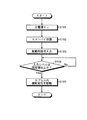
次に、図5のフローチャートを用いて、カプセル型内視鏡2の動作を説明する。図5において、たとえば、被検体1内への導入前のカプセル型内視鏡2は、内部に外部磁場によってオン・オフする図示しないリードスイッチを備え、この外部磁場を供給する永久磁石を含むパッケージに収容された状態で保管されている。この状態では、カプセル型内視鏡2は駆動しない。
Next, the operation of the
そして、飲み込み時に、このカプセル型内視鏡2がパッケージから取り出されると、パッケージの永久磁石から離隔してカプセル型内視鏡が磁力の影響を受けなくなり、主電源がオンして(ステップ101)、スタンバイ状態となる(ステップ102)。このスタンバイ状態では、図2に示すように、システムコントロール回路26とコントロール信号検出回路28とに電池29から電力が供給されて、受信アンテナ部27での無線信号の受信が可能な状態となるが、その他の機能実行回路40に対しては電力供給が行われていない。
When the
このスタンバイ状態において、カプセル型内視鏡2が被検体1内に導入されると、通信装置3から起動用信号がカプセル型内視鏡2に対して送信されることとなる。そして、カプセル型内視鏡2の受信アンテナ部27で、この起動用信号が受信され(ステップ103)、さらにコントロール信号検出回路28によって、所定値以上の入力レベルの起動用信号が検出されると(ステップ104)、コントロール信号検出回路28は、システムコントロール回路26にコントロール信号を出力する。システムコントロール回路26は、このコントロール信号を取り込むと、電池からの駆動電力をカプセル内機能実行回路40(この実施の形態では、LED駆動回路21、CCD駆動回路23およびRF送信ユニット24)に供給して、カプセル内機能実行回路40の駆動を制御する(ステップ105)。
When the
そして、カプセル内機能実行回路40に駆動電力が供給されることにより、LED駆動回路21、CCD駆動回路23およびRF送信ユニット24がパワーオンしてアクティブ状態となる。そして、LED20によって被検体1内に照明光が照射され、その反射光をCCD22によって受光し、得られた画像データをRF送信ユニット24によって送信アンテナ部25を介して、被検体1の外部の通信装置3に送信することが可能となる。
When the driving power is supplied to the intracapsule
このように、この実施の形態では、カプセル型内視鏡が被検体内に導入された後に、外部から送信される入力レベルが所定値以上の起動用信号を、被検体内のカプセル型内視鏡で検出してカプセル内機能実行回路に駆動電力を供給し、カプセル内機能実行回路の駆動を制御するので、カプセル型内視鏡の駆動を開始するタイミングを、カプセル型内視鏡が被検体内に確実に導入された後に行うことでき、これによって被検体内での画像収集および画像送信を的確に行うことができる。 As described above, in this embodiment, after the capsule endoscope is introduced into the subject, the activation signal having an input level transmitted from the outside having a predetermined value or more is transmitted to the capsule endoscope in the subject. The capsule endoscope performs the detection of the capsule endoscope and supplies the drive power to the capsule function execution circuit to control the drive of the capsule function execution circuit. It is possible to carry out the image after it has been reliably introduced into the inside of the subject, whereby it is possible to accurately perform image collection and image transmission within the subject.
ところで、上述した実施の形態1の無線型被検体内情報取得システムでは、被検者の口内に導入された瞬間に起動用信号を送信すると、その直後にカプセル内機能実行回路40が駆動してしまうことが考えられ、このように飲み込んだ瞬間ではなく、カプセル型内視鏡2が確実に検査対象の臓器に導入された状態でカプセル内機能実行回路を駆動させたい場合がある。
By the way, in the wireless in-vivo information acquiring system of the first embodiment described above, when the activation signal is transmitted at the moment when it is introduced into the subject's mouth, the intra-capsule
このような要望に対しては、たとえばコントロール信号検出回路28にタイマ機能を設け、起動用信号が検出されてから一定時間後に、コントロール信号をシステムコントロール回路26に出力するように設定し、この一定時間後にカプセル内機能実行回路に駆動電力を供給して、被検体内の被検部位の撮像、画像データの収集および送信を行うことも可能である。
In response to such a demand, for example, the control
たとえば、カプセル型内視鏡2が胃に導入されてから画像データの収集および送信を始める場合には、起動用信号が送信されてからカプセル型内視鏡2が胃に到達するまでの一定時間を、タイマに予めセットしておき、コントロール信号検出回路28は、起動用信号を検出すると、タイマを起動させる。そして、コントロール信号検出回路28は、一定時間経過後にコントロール信号をシステムコントロール回路26に出力して、システムコントロール回路26内のスイッチ素子をオン状態にさせる。これによって、カプセル型内視鏡が確実に検査対象の胃に導入された時点で、電池29からカプセル内機能実行回路40に駆動電力が供給され、LED20によって照明され、かつCCD22によって撮像された胃内部の画像データの外部への送信が行われることになる。
For example, when the collection and transmission of image data is started after the
このように、この実施の形態では、カプセル型内視鏡が検査対象に導入された時点で、カプセル内機能実行回路に駆動電力の供給を行うので、電力消費を削減できるとともに、駆動を開始するタイミングを、予め設定された任意のタイミングで行うことで、さらに被検体内での検査対象の画像収集および画像送信を的確に行うことができる。 As described above, in this embodiment, when the capsule endoscope is introduced into the examination target, the drive power is supplied to the capsule function execution circuit, so that the power consumption can be reduced and the drive is started. By performing the timing at an arbitrary timing set in advance, it is possible to accurately perform image collection and image transmission of the examination target in the subject.
また、この実施の形態では、システムコントロール回路26がラッチ回路を備えた構成を有する。このため、ステップ105において、カプセル内機能実行回路40の駆動が開始された後は、コントロール信号の入力の有無に関わらず、カプセル内機能実行回路40は駆動し続けることとなる。そこで、このカプセル内機能実行回路40の駆動停止は、たとえばシステムコントロール回路26内に設けた別のタイマ機能などによって行うように構成することも可能である。
In this embodiment, the
さらに、この実施の形態では、外部装置32のコントロール信号入力ユニット36は、カプセル型内視鏡2内の機能実行回路40の機能を制御するための各種のコントロール信号を生成することが可能であり、カプセル型内視鏡2のコントロール信号検出回路28は、これらコントロール信号を検出し、検出したコントロール信号に応じて、カプセル型内視鏡2内の各機能実行回路をそれぞれ制御することが可能に構成されている。
Furthermore, in this embodiment, the control
そこで、この実施の形態では、コントロール信号入力ユニット36によって、起動用信号の後に、起動開始指示を示す所定のデータパターンからなるコントロール信号(以下、「起動開始指示信号」という)を生成し、このコントロール信号をカプセル型内視鏡2に送信するように構成することも可能である。カプセル型内視鏡2のコントロール信号検出回路28では、起動用信号を検出した後に、受信されたコントロール信号のデータパターンに基づいて起動開始指示信号を検出して、この起動開始指示信号をシステムコントロール回路26に対して出力する。
Therefore, in this embodiment, the control
このように、起動開始指示を示すコントロール信号を起動用信号に続けて送信することで、たとえば起動用信号と同程度の入力レベルのノイズが発生した場合に、図5におけるステップ104の入力レベルを満足しても、その後に送信されるコントロール信号のデータパターンに基づいて、カプセル内機能実行回路の駆動制御かどうか判断できるので、ノイズによる誤判断を防止でき、さらに被検体内での検査対象の画像収集および画像送信を的確に行うことができる。 In this way, by transmitting the control signal indicating the start start instruction following the start signal, for example, when noise of the same input level as that of the start signal is generated, the input level of step 104 in FIG. Even if satisfied, it can be determined whether or not it is drive control of the function execution circuit in the capsule based on the data pattern of the control signal transmitted thereafter. Image collection and image transmission can be performed accurately.
(実施の形態2)
図6は、図1に示した実施の形態2にかかるカプセル型内視鏡の回路構成を示す回路図である。この実施の形態では、カプセル型内視鏡2内に電池を備えない場合を想定しており、通信装置3は、起動用信号として、カプセル内機能実行回路40に電力を供給するための給電用信号を、カプセル型内視鏡に対して送信している。
(Embodiment 2)
FIG. 6 is a circuit diagram showing a circuit configuration of the capsule endoscope according to the second embodiment shown in FIG. In this embodiment, it is assumed that a battery is not provided in the
図6において、カプセル型内視鏡2は、受信アンテナ部27と、レギュレータまたはDC−DCコンバータからなる電源IC41と、カプセル内機能実行回路40とを備えている。受信アンテナ部27は、起動用信号を受信して起電力を生じるコイル27aと、起電力を整流するダイオード27bと、電力供給機能を有するコンデンサ27cとを備える。
In FIG. 6, the
また、この実施の形態の通信装置3は、図4に示した通信装置のコントロール信号入力ユニット36の代わりに、図7に示すように、給電用信号の生成および発振周波数の規定を行う発振器50を、RF送信ユニット37に接続された点のみが異なる。
Further, the
このような構成において、通信装置3から発振された特定周波数帯の起動用信号(給電用信号)をカプセル型内視鏡2が受信すると、コイル27aに起電力が生じ、この発生した起電力によってコンデンサ27cの電圧が一定値以上になると、電源IC41が起動してカプセル内機能実行回路40に電力が供給されて、起動可能なアクティブ状態になる。
In such a configuration, when the
このように、この実施の形態では、カプセル型内視鏡が被検体内に導入された後に、外部から送信される給電用信号を受信し、この給電用信号に基づいて、カプセル内機能実行回路に電力を供給し、カプセル内機能実行回路の駆動を制御するので、カプセル型内視鏡の駆動を開始するタイミングを、カプセル型内視鏡が被検体内に確実に導入された後に行うことでき、これによって被検体内での画像収集および画像送信を的確に行うことができる。 As described above, in this embodiment, after the capsule endoscope is introduced into the subject, the power feeding signal transmitted from the outside is received, and the capsule function execution circuit is based on the power feeding signal. Since the power is supplied to the device and the drive of the capsule function execution circuit is controlled, the timing for starting the drive of the capsule endoscope can be performed after the capsule endoscope is reliably introduced into the subject. Thus, it is possible to accurately perform image collection and image transmission within the subject.
(実施の形態3)
図8および図9は、実施の形態3にかかるカプセル型内視鏡および通信装置の内部構成を示すブロック図である。この実施の形態では、カプセル型内視鏡2に電力を供給する際に、給電用信号に起動用信号を重畳してカプセル型内視鏡2に対して送信している。
(Embodiment 3)
FIG. 8 and FIG. 9 are block diagrams illustrating the internal configuration of the capsule endoscope and the communication device according to the third embodiment. In this embodiment, when power is supplied to the
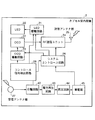
図8において、カプセル型内視鏡2は、図2に示したシステムコントロール回路26、受信アンテナ部27、コントロール信号検出回路28およびカプセル内機能実行回路を備えるとともに、受信アンテナ部27で受信した信号から給電用信号を分離する分離回路42と、分離された給電用信号から電力を再生する電力再生回路43と、再生された電力を昇圧する昇圧回路44と、昇圧された電力を蓄積する蓄電器45を備える。コントロール信号検出回路28は、分離回路42で給電用信号と分離された成分から所定の入力レベル以上の起動用信号を検出し、この検出に応じてシステムコントロール回路26に対してコントロール信号を出力している。
8, the
システムコントロール回路26は、たとえば各構成要素と蓄電器45との間に接続されたスイッチ素子およびラッチ回路(図示せず)などを備えている。そして、このラッチ回路は、上述したコントロール信号検出回路28からのコントロール信号(起動用信号)が入力すると、スイッチ素子をオン状態にし、それ以降はこのオン状態を保持して、駆動電力をカプセル型内視鏡2内の機能実行回路に供給している。
The
また、通信装置3は、実施の形態1の通信装置と同様に、送受信ジャケット31と、外部装置32とを備える。送受信ジャケット31は、実施の形態1と同一構成のジャケットであり、外部装置32は、図4に示したRF受信ユニット33、画像処理ユニット34、記憶ユニット35、コントロール信号入力ユニット36、電力供給ユニット38を備えるとともに、給電用信号の生成および発振周波数の規定を行う発振器50と、発振器50から出力される給電用信号にコントロール信号入力ユニットから出力される起動用信号を重畳させて合成する重畳回路51と、合成された信号を無線周波数に変換して出力するRF送信ユニット回路37とを備える。外部装置32では、重畳回路51で合成され、かつRF送信ユニット37で変換された信号が送信用アンテナB1〜Bmに送られ、カプセル型内視鏡2に対して送信される。
In addition, the
このように、この実施の形態では、カプセル型内視鏡が被検体内に導入された後に、給電用信号と起動用信号とを合成させた信号を外部から送信して、カプセル型内視鏡に受信させ、分離後に起動用信号を検出して、給電用信号に基づいて蓄電器に蓄積された駆動電力を、カプセル内機能実行回路に供給し、カプセル内機能実行回路の駆動を制御するので、カプセル型内視鏡の駆動を開始するタイミングを、カプセル型内視鏡が被検体内に確実に導入された後に行うことでき、これによって被検体内での画像収集および画像送信を的確に行うことができ、さらにはこの駆動電力の供給とほぼ同時にカプセル型内視鏡内の蓄電器に電力を蓄積して、駆動電力の消尽を防ぐことができる。 As described above, in this embodiment, after the capsule endoscope is introduced into the subject, a signal obtained by synthesizing the power feeding signal and the activation signal is transmitted from the outside, and the capsule endoscope And detecting the activation signal after separation, supplying the drive power accumulated in the capacitor based on the power supply signal to the intracapsule function execution circuit, and controlling the drive of the intracapsule function execution circuit. The timing to start driving the capsule endoscope can be performed after the capsule endoscope has been reliably introduced into the subject, thereby accurately performing image collection and image transmission within the subject. Furthermore, it is possible to prevent the driving power from being exhausted by accumulating electric power in the battery in the capsule endoscope almost simultaneously with the supply of the driving power.
また、実施の形態2,3においても、実施の形態1に示したタイマ機能を設けて、カプセル型内視鏡が確実に検査対象の臓器に導入されてから、カプセル内機能実行回路に電力供給を行うように設定することも可能である。さらに、実施の形態2,3においても、実施の形態1で示した起動開始指示を示すコントロール信号を起動用信号に続けて送信するように設定することも可能である。 Also in the second and third embodiments, the timer function shown in the first embodiment is provided, and power is supplied to the intracapsule function execution circuit after the capsule endoscope is reliably introduced into the organ to be examined. It is also possible to set to perform. Further, in the second and third embodiments, it is possible to set so that the control signal indicating the activation start instruction shown in the first embodiment is transmitted following the activation signal.
また、本発明では、起動用信号を特定無線周波数の信号で構成させて、通信装置の外部装置から被検体内に導入されたカプセル内視鏡に対して送信し、カプセル内視鏡のコントロール信号検出回路でこの特定無線周波数の起動用信号を検出するように構成することも可能である。この場合には、さらにノイズによる誤判断を防止でき、被検体内での検査対象の画像収集および画像送信をより的確に行うことができる。 Further, in the present invention, the activation signal is configured by a signal of a specific radio frequency, transmitted from the external device of the communication device to the capsule endoscope introduced into the subject, and the control signal of the capsule endoscope The detection circuit may be configured to detect the activation signal of the specific radio frequency. In this case, it is possible to further prevent erroneous determination due to noise, and it is possible to more accurately perform image collection and image transmission of the examination target in the subject.
1 被検体
2 カプセル型内視鏡
3 通信装置
4 表示装置
5 携帯型記録媒体
21 LED駆動回路
22 CCD
23 CCD駆動回路
24,37 RF送信ユニット
25 送信アンテナ部
26 システムコントロール回路
27 受信アンテナ部
27a コイル
27b ダイオード
27c,28b コンデンサ
28 コントロール信号検出回路
28a コントロール信号出力部
28c 抵抗
29 電池
31 送受信ジャケット
32 外部装置
33 RF受信ユニット
34 画像処理ユニット
35 記憶ユニット
36 コントロール信号入力ユニット
38 電力供給ユニット
40 カプセル内機能実行回路
41 電源IC
42 分離回路
43 電力再生回路
44 昇圧回路
45 蓄電器
50 発振器
51 重畳回路
A1〜An 受信用アンテナ
B1〜Bm 送信用アンテナ
DESCRIPTION OF SYMBOLS 1
23
42
Claims (4)
前記無線型被検体内情報取得装置は、
前記導入された被検体内において所定の機能を実行する機能実行手段と、
前記被検体外からの無線信号を受信可能に構成された無線受信手段と、
前記無線受信手段によって受信された信号から給電用信号を分離し、この分離された給電用信号から前記機能実行手段に供給する電力を再生する電力再生手段と、
前記無線受信手段によって受信された信号から給電用信号を分離した起動用信号の入力に応じて、前記機能実行手段の起動を制御する起動手段と、
を備え、前記通信装置は、
前記無線通信された情報を受信する無線受信手段と、
前記給電用信号と前記起動用信号とを重畳した前記無線信号を無線送信する無線送信手段と、
を備えたことを特徴とする無線型被検体内情報取得システム。 A wireless in-subject information acquisition device introduced into the subject, and a communication device that is arranged outside the subject and acquires information obtained by the wireless in-subject information acquisition device by wireless communication. In the wireless in-vivo information acquisition system,
The wireless in-vivo information acquiring apparatus includes:
Function execution means for executing a predetermined function in the introduced subject;
Wireless receiving means configured to be able to receive a wireless signal from outside the subject;
A power regeneration means for separating a power feeding signal from a signal received by the wireless receiving means, and regenerating power supplied to the function execution means from the separated power feeding signal;
An activation unit that controls activation of the function execution unit according to an input of an activation signal obtained by separating a power feeding signal from a signal received by the wireless reception unit;
The communication device comprises:
Wireless receiving means for receiving the wirelessly communicated information;
Wireless transmission means for wirelessly transmitting the wireless signal in which the power feeding signal and the activation signal are superimposed;
A wireless in-vivo information acquiring system comprising:
Priority Applications (1)
| Application Number | Priority Date | Filing Date | Title |
|---|---|---|---|
| JP2003343560A JP4590176B2 (en) | 2003-10-01 | 2003-10-01 | Wireless in-vivo information acquisition system |
Applications Claiming Priority (1)
| Application Number | Priority Date | Filing Date | Title |
|---|---|---|---|
| JP2003343560A JP4590176B2 (en) | 2003-10-01 | 2003-10-01 | Wireless in-vivo information acquisition system |
Publications (3)
| Publication Number | Publication Date |
|---|---|
| JP2005103147A JP2005103147A (en) | 2005-04-21 |
| JP2005103147A5 JP2005103147A5 (en) | 2006-11-24 |
| JP4590176B2 true JP4590176B2 (en) | 2010-12-01 |
Family
ID=34537491
Family Applications (1)
| Application Number | Title | Priority Date | Filing Date |
|---|---|---|---|
| JP2003343560A Expired - Fee Related JP4590176B2 (en) | 2003-10-01 | 2003-10-01 | Wireless in-vivo information acquisition system |
Country Status (1)
| Country | Link |
|---|---|
| JP (1) | JP4590176B2 (en) |
Families Citing this family (5)
| Publication number | Priority date | Publication date | Assignee | Title |
|---|---|---|---|---|
| JP4451217B2 (en) | 2004-06-01 | 2010-04-14 | オリンパス株式会社 | Capsule type communication system, capsule type medical device and biological information receiving device |
| CN100440981C (en) * | 2005-12-16 | 2008-12-03 | 清华大学 | Automatically requesting retransmission communication method of high code rate super short distance for wireless endoscope system |
| JP5284592B2 (en) * | 2007-02-19 | 2013-09-11 | オリンパス株式会社 | In-subject information acquisition system |
| CN110545712B (en) * | 2017-03-07 | 2022-12-30 | 南安普敦大学 | Intrauterine monitoring system |
| CN109770835B (en) * | 2019-02-15 | 2021-08-13 | 重庆金山医疗器械有限公司 | Capsule type endoscope system function detection device and method |
Citations (3)
| Publication number | Priority date | Publication date | Assignee | Title |
|---|---|---|---|---|
| JP2001224551A (en) * | 2000-02-15 | 2001-08-21 | Asahi Optical Co Ltd | Capsule endoscope |
| JP2002330942A (en) * | 2000-12-18 | 2002-11-19 | Biosense Inc | Telemetric reader/charger device for medical sensor |
| JP2003135389A (en) * | 2001-11-06 | 2003-05-13 | Olympus Optical Co Ltd | Capsule type medical apparatus |
-
2003
- 2003-10-01 JP JP2003343560A patent/JP4590176B2/en not_active Expired - Fee Related
Patent Citations (3)
| Publication number | Priority date | Publication date | Assignee | Title |
|---|---|---|---|---|
| JP2001224551A (en) * | 2000-02-15 | 2001-08-21 | Asahi Optical Co Ltd | Capsule endoscope |
| JP2002330942A (en) * | 2000-12-18 | 2002-11-19 | Biosense Inc | Telemetric reader/charger device for medical sensor |
| JP2003135389A (en) * | 2001-11-06 | 2003-05-13 | Olympus Optical Co Ltd | Capsule type medical apparatus |
Also Published As
| Publication number | Publication date |
|---|---|
| JP2005103147A (en) | 2005-04-21 |
Similar Documents
| Publication | Publication Date | Title |
|---|---|---|
| US8038599B2 (en) | Wireless in-vivo information acquiring apparatus, wireless in-vivo information acquiring system, and communication apparatus | |
| JP3993546B2 (en) | In-subject introduction apparatus and wireless in-subject information acquisition system | |
| JP4398204B2 (en) | In-subject introduction apparatus and wireless in-subject information acquisition system | |
| KR100889093B1 (en) | Radio-type in-subject information acquisition system, device for introduction into subject, and outside-subject device | |
| US7837617B2 (en) | Intrabody introduced device | |
| US20090292167A1 (en) | Capsule medical apparatus and method of charging capsule medical apparatus | |
| US20070260116A1 (en) | Body-insertable apparatus and receiving apparatus for recognizing remaining power amount | |
| WO2006103778A1 (en) | Wireless device for acquiring information on inside of subject and wireless system for acquiring information on inside of subject | |
| JP4515112B2 (en) | Wireless in-vivo information acquisition device | |
| JP4590176B2 (en) | Wireless in-vivo information acquisition system | |
| JP4804831B2 (en) | In-subject information acquisition system | |
| JP4445733B2 (en) | In-subject introduction apparatus and wireless in-subject information acquisition system | |
| JP4590175B2 (en) | Wireless in-vivo information acquisition system | |
| JP4335086B2 (en) | Intra-subject introduction device | |
| JP4398193B2 (en) | Wireless in-vivo information acquisition system | |
| JP4656825B2 (en) | In-subject introduction apparatus and wireless in-subject information acquisition system | |
| JP4709483B2 (en) | Wireless in-subject information acquisition apparatus and wireless in-subject information acquisition system | |
| JP5185991B2 (en) | Wireless in-subject information acquisition apparatus and wireless in-subject information acquisition system | |
| JP2005124314A (en) | Power supply device and power supply system | |
| AU2008202335B2 (en) | Intra-subject information acquiring system |
Legal Events
| Date | Code | Title | Description |
|---|---|---|---|
| A621 | Written request for application examination |
Free format text: JAPANESE INTERMEDIATE CODE: A621 Effective date: 20061002 |
|
| A521 | Written amendment |
Free format text: JAPANESE INTERMEDIATE CODE: A523 Effective date: 20061005 |
|
| A977 | Report on retrieval |
Free format text: JAPANESE INTERMEDIATE CODE: A971007 Effective date: 20090916 |
|
| A131 | Notification of reasons for refusal |
Free format text: JAPANESE INTERMEDIATE CODE: A131 Effective date: 20090929 |
|
| A521 | Written amendment |
Free format text: JAPANESE INTERMEDIATE CODE: A523 Effective date: 20091130 |
|
| A131 | Notification of reasons for refusal |
Free format text: JAPANESE INTERMEDIATE CODE: A131 Effective date: 20091222 |
|
| A521 | Written amendment |
Free format text: JAPANESE INTERMEDIATE CODE: A523 Effective date: 20100216 |
|
| TRDD | Decision of grant or rejection written | ||
| A01 | Written decision to grant a patent or to grant a registration (utility model) |
Free format text: JAPANESE INTERMEDIATE CODE: A01 Effective date: 20100907 |
|
| A01 | Written decision to grant a patent or to grant a registration (utility model) |
Free format text: JAPANESE INTERMEDIATE CODE: A01 |
|
| A61 | First payment of annual fees (during grant procedure) |
Free format text: JAPANESE INTERMEDIATE CODE: A61 Effective date: 20100913 |
|
| FPAY | Renewal fee payment (event date is renewal date of database) |
Free format text: PAYMENT UNTIL: 20130917 Year of fee payment: 3 |
|
| S531 | Written request for registration of change of domicile |
Free format text: JAPANESE INTERMEDIATE CODE: R313531 |
|
| R350 | Written notification of registration of transfer |
Free format text: JAPANESE INTERMEDIATE CODE: R350 |
|
| LAPS | Cancellation because of no payment of annual fees |