JP4589989B2 - Cyclone separator - Google Patents
Cyclone separator Download PDFInfo
- Publication number
- JP4589989B2 JP4589989B2 JP2008174478A JP2008174478A JP4589989B2 JP 4589989 B2 JP4589989 B2 JP 4589989B2 JP 2008174478 A JP2008174478 A JP 2008174478A JP 2008174478 A JP2008174478 A JP 2008174478A JP 4589989 B2 JP4589989 B2 JP 4589989B2
- Authority
- JP
- Japan
- Prior art keywords
- dust
- current
- value
- collection container
- rotation
- Prior art date
- Legal status (The legal status is an assumption and is not a legal conclusion. Google has not performed a legal analysis and makes no representation as to the accuracy of the status listed.)
- Expired - Fee Related
Links
Images


Description
本発明は,捕集対象物を遠心分離するサイクロン分離装置に係り,特に,捕集された塵埃などの捕集対象物の量を正確に検知して,安全に運転することができるサイクロン分離装置に関するものである。 The present invention relates to a cyclone separation device that centrifuges a collected object, and more particularly, a cyclone separation apparatus that can accurately detect the amount of collected object such as collected dust and operate safely. It is about.
従来から,略円筒状の捕集容器の中心部に設けられた排気部から前記捕集容器内の空気を排気することにより,前記捕集容器の円周部に設けられた空気吸い込み部から吸い込まれた空気を前記捕集容器の内周面に沿って旋回させた後,フィルタ手段を経て前記排気部から排気し,前記空気に含まれる比較的大きい塵埃を前記捕集容器の底部で捕集すると共に,比較的小さい塵埃を前記フィルタ手段において捕集するサイクロン分離装置の一例としてのサイクロン集塵装置が,特許文献1として知られている。
このサイクロン集塵装置は,比較的大きい塵埃を旋回させることで遠心力によって捕集し,空気流に乗って飛翔する比較的小さい塵埃については,空気流中においたフィルタ手段によって捕集するものであるため,騒音が少なく,集塵効率についても改善されたものである。
Conventionally, the air in the collection container is exhausted from the exhaust part provided in the central part of the substantially cylindrical collection container, and is sucked in from the air suction part provided in the circumferential part of the collection container. The collected air is swung along the inner peripheral surface of the collection container, and then exhausted from the exhaust part through the filter means, so that relatively large dust contained in the air is collected at the bottom of the collection container. In addition,
This cyclone dust collecting device collects relatively large dust by centrifugal force by swirling relatively large dust, and collects relatively small dust flying on an air flow by a filter means placed in the air flow. Therefore, noise is low and dust collection efficiency is improved.
上記のようなサイクロン集塵装置を一般家庭で使用すると,布団や衣類から生じる綿ホコリが集塵ごみ容積の大半を占める。この綿ホコリを構成する繊維等は,それ自体が弾性を持つため,塵埃の密度は小さい割りに体積が大きく,捕集容器がすぐにいっぱいになるため,頻繁に集塵部から取り除く(捨てる)必要がある。また,このような塵埃は,軽くて容易に飛散するため,外部のごみ箱等に廃棄する際,塵埃が舞い散って再飛散することで使用者が不快に感じるという問題がある。 When the above cyclone dust collector is used in a general household, cotton dust generated from futons and clothing occupies most of the dust collection volume. The fibers that make up this cotton dust are elastic themselves, so the dust density is small, but the volume is large and the collection container fills up quickly, so it is frequently removed (discarded) from the dust collection part. There is a need. In addition, since such dust is light and easily scattered, there is a problem that the user feels uncomfortable when the dust is scattered and re-scattered when disposed in an external trash can.
しかしながら,上記特許文献1に記載のサイクロン集塵装置は,あくまで空気の流れに頼って塵埃を捕集するものであるため,捕集された前記繊維などの低密度の埃を一定以上に圧縮することが出来ず,限られた塵埃の捕集空間における塵埃の集積度をそれほど向上させることが出来るものではない。従って,捕集された塵埃を頻繁に捨てないと捕集効率が低下するので,塵埃を捨てる手間がかかる点,あるいは,塵埃を捨てる時に,塵埃が硬く圧縮されておらず,空気中で分散されやすいので,ごみ箱等に廃棄する際,塵埃が舞い散って再飛散することによる不快感を解消することが出来ないという問題を解決することが出来ない。
However, since the cyclone dust collector described in
このような課題を解決するためには,捕集された塵埃を出来るだけ固く圧縮する必要がある。このような,塵埃の圧縮手段を備えたサイクロン分離装置が本出願人によって出願された(特願2008−072942)。このサイクロン分離装置は,内周面が略円筒状の捕集容器を備え,該捕集容器の円周部にその周方向に設けられた空気流入口から吸い込まれた空気を前記略円筒状の内周面に沿って旋回させた後,前記捕集容器の中心部からフィルタ手段を経て排気することにより,前記空気に含まれる比較的大きい捕集対象物を前記捕集容器の底部で捕集すると共に,比較的小さい捕集対象物を前記フィルタ手段において捕集するものであり,さらに前記捕集容器内に,該捕集容器の垂直中心軸を中心とする螺旋状曲面を備え,前記垂直中心軸の周りに回転可能な圧縮部材を備えたものである。 In order to solve such problems, it is necessary to compress the collected dust as hard as possible. The present applicant has filed an application for such a cyclone separation device equipped with dust compression means (Japanese Patent Application No. 2008-072942). The cyclone separation device includes a collection container having an approximately cylindrical inner peripheral surface, and air sucked from an air inlet provided in a circumferential direction on a circumferential portion of the collection container. After swirling along the inner peripheral surface, a relatively large collection target contained in the air is collected at the bottom of the collection container by exhausting through the filter means from the center of the collection container. In addition, a relatively small collection object is collected by the filter means, and the collection container is further provided with a spiral curved surface centered on a vertical central axis of the collection container, A compression member rotatable around a central axis is provided.
このサイクロン分離装置では,上記圧縮部材が上記垂直中心軸を中心に回転することによって,上記螺旋状曲面の下面で捕集された塵埃などの捕集対象物が硬く圧縮されているため,なんども塵埃を捨てる必要がなく,塵埃を捨てる手間が省力される。
あるいは,塵埃を捨てる時に,塵埃が空気中で分散され,ごみ箱等に廃棄する際,塵埃が舞い散って再飛散することによる不快感を解消することが出来るといった,多くの長所が発揮される。
Or, when the dust is thrown away, the dust is dispersed in the air, and when it is discarded in the trash can, many advantages are exhibited such that the discomfort caused by the dust flying and re-scattering can be eliminated.
このように上記出願(特願2008−072942)の明細書に開示されたサイクロン分離装置は優れた機能を発揮するが,上記のように塵埃が硬く圧縮されるため,捕集された塵埃の量がある程度以上に多くなると,圧縮部材の回転にはそれなりの消費電力が必要となる。また,それを超えて更に圧縮部材の回転を継続すると,硬い塵埃の抵抗によって圧縮部材を回転させるモータなどの圧縮部材駆動手段に掛かる負荷が大きくなり,消費電力の面でもまたモータの過負荷の面でも望ましくない状態になることが考えられる。
そのため上記モータなどの過負荷を検知してモータを停止させるなどの処理とすることが望ましいが,実際には,モータが過負荷になる前に使用者に警報を発するなどの事前の対応を行うことが,モータへの過負荷を防止してモータの寿命を延ばすといった点から望ましい。
さらに,モータが過負荷になる前に実質的な捕集物の量を検知して使用者に警報を発するなどの処理をすることが望ましいが,捕集物の量は捕集容器の中で偏在するので単純にはその量を正確に測定することは困難である。
そのため,本発明の発明者は,鋭意努力の末,モータ電流と捕集対象物の量との間に技術的な関係があることを突き止め,これにより捕集物の量を間接的に且つ正確に検知することができることを見出した。
As described above, the cyclone separator disclosed in the specification of the above-mentioned application (Japanese Patent Application No. 2008-072942) exhibits an excellent function. However, since dust is compressed hard as described above, the amount of collected dust When the value of the pressure increases more than a certain level, the rotation of the compression member requires a certain amount of power consumption. If the rotation of the compression member continues further beyond that, the load applied to the compression member driving means such as a motor that rotates the compression member due to the resistance of hard dust increases, and in terms of power consumption, the motor is overloaded. It can be considered that the surface is also undesirable.
For this reason, it is desirable to detect the overload of the motor, etc., and stop the motor. However, in practice, take precautions such as issuing an alarm to the user before the motor is overloaded. This is desirable from the standpoint of preventing the motor from being overloaded and extending the life of the motor.
In addition, it is desirable to detect the amount of the collected material before the motor is overloaded and issue a warning to the user. However, the amount of the collected material is stored in the collection container. Since it is unevenly distributed, it is difficult to measure the amount accurately simply.
For this reason, the inventors of the present invention, after diligent efforts, have determined that there is a technical relationship between the motor current and the amount of the object to be collected, thereby indirectly and accurately determining the amount of the object to be collected. It was found that it can be detected.
従って,本発明は上記事情に鑑み創案されたものであり,前記圧縮部材の回転抵抗となる捕集対象物の蓄積量を圧縮部材の回転駆動手段の電流値から間接的に且つ正確に求めて,圧縮部材の回転駆動手段を過負荷から保護することの出来るサイクロン分離装置を提供することである。 Accordingly, the present invention has been devised in view of the above circumstances, and indirectly and accurately obtains the accumulation amount of an object to be collected that becomes the rotational resistance of the compression member from the current value of the rotation drive means of the compression member. An object of the present invention is to provide a cyclone separation device capable of protecting the rotational drive means of the compression member from overload.
上記目的を達成するために,本出願にかかる発明は,
内周面が略円筒状の捕集容器を備え,該捕集容器の円周部にその周方向に設けられた空気流入口から吸い込まれた空気を前記略円筒状の内周面に沿って旋回させた後,前記捕集容器の中心部からフィルタ手段を経て排気することにより,前記空気に含まれる比較的大きい捕集対象物を前記捕集容器の底部で捕集すると共に,比較的小さい捕集対象物を前記フィルタ手段において捕集するサイクロン分離装置であって,
前記捕集容器内に,該捕集容器の垂直中心軸を中心とする螺旋状曲面を備え,前記垂直中心軸の周りに回転可能な圧縮部材と,
前記捕集容器の内面の一部に設けられ,前記捕集容器内面の一部について他の部分と較べて捕集対象物に対する摩擦係数を変化させることで前記圧縮部材の回転に伴って該圧縮部材に押されて回転しようとする前記捕集容器内面に蓄積された捕集対象物の回転を抑制する回転抑制手段と,
前記圧縮部材を前記垂直中心軸周りに回転駆動する圧縮部材駆動手段の電流を検知する電流検知手段と,
前記電流検知手段による電流の検知結果に基づいて,当該サイクロン分離装置を制御する制御手段とを備えてなるサイクロン分離装置である。
前記回転抑制手段は具体的には,前記捕集容器内面の一部貼り付けられたゴム片であったり,あるいは,前記捕集容器内面の一部の内面に形成された凹凸が好ましい例としてあげられる。
前記制御手段は,前記電流検知手段の検知結果に基づいて蓄積された塵埃の量を推定し
,圧縮部材駆動手段が過負荷になる前に警報を発する。例えば,圧縮部材駆動手段の電流値に関する閾値として予め定められた第1の閾値を記憶する電流値記憶手段を備え,前記電流検知手段による電流の検知結果が前記電流値記憶手段に記憶された前記第1の閾値を超えた場合に,前記制御手段が,使用者に対して警報を発するようにすることが望ましい。
さらに,電流値記憶手段が,更に,前記第1の閾値よりも大きい第2の閾値を予め記憶しており,前記電流検知手段による電流の検知結果が前記第2の閾値を超えた場合に,前記制御手段が,使用者に対して警報を発すると共に,当該サイクロン分離装置の運転を停止するようにすれば,圧縮部材駆動手段の過負荷は完全に防止される。
前記電流の検知結果,前記第1及び前記第2の閾値として,周期的に変化する電流の最大値と最小値との差に基づく値を採用することができる。
また,前記電流の検知結果,前記第1及び前記第2の閾値として,周期的に変化する電流のピーク値間の周期に基づく値を採用することも有益である。
更にまた,前記電流の検知結果,前記第1及び前記第2の閾値が,前記電流検知手段の検知電流についての所定時間の平均値又は検知電流の変動周期の1周期若しくは複数周期の平均値に基づく値であってもよい。
当該サイクロン分離装置の具体例として,捕集対象物を塵埃とするサイクロン集塵装置が挙げられる。
In order to achieve the above object, the invention according to the present application is
An inner peripheral surface is provided with a substantially cylindrical collection container, and air sucked from an air inlet provided in the circumferential direction on the circumferential portion of the collection container is disposed along the substantially cylindrical inner peripheral surface. After swirling, the relatively large collection object contained in the air is collected at the bottom of the collection container and is relatively small by exhausting from the center of the collection container through the filter means. A cyclone separation device for collecting an object to be collected in the filter means,
A compression member having a spiral curved surface centered on the vertical central axis of the collection container in the collection container, and rotatable about the vertical central axis;
It is provided on a part of the inner surface of the collection container, and the compression member is rotated along with the rotation of the compression member by changing the friction coefficient with respect to the collection object with respect to a part of the inner surface of the collection container as compared with other parts. Rotation suppression means for suppressing rotation of the collection object accumulated on the inner surface of the collection container which is pushed by the member and is about to rotate;
Current detection means for detecting the current of the compression member driving means for rotating the compression member around the vertical central axis;
A cyclone separator comprising control means for controlling the cyclone separator based on a current detection result by the current detector .
The front Symbol rotation suppressing means specifically, or a rubber strip attached portion of the collecting container the inner surface, or as part of irregularities preferred example formed on an inner surface of the collecting container the inner surface can give.
The control means estimates the amount of accumulated dust based on the detection result of the current detection means, and issues a warning before the compression member driving means is overloaded. For example, a current value storage unit that stores a first threshold value that is predetermined as a threshold value related to the current value of the compression member driving unit is provided, and a current detection result by the current detection unit is stored in the current value storage unit. When the first threshold value is exceeded, it is desirable that the control means issues a warning to the user.
Further, the current value storage means further stores in advance a second threshold value larger than the first threshold value, and when the current detection result by the current detection means exceeds the second threshold value, If the control means issues a warning to the user and stops the operation of the cyclone separator, overloading of the compression member driving means is completely prevented.
As the detection result of the current and the first and second threshold values, values based on the difference between the maximum value and the minimum value of the periodically changing current can be adopted.
It is also beneficial to employ a value based on a period between periodically changing current peak values as the current detection result and the first and second threshold values.
Furthermore, the detection result of the current, the first and second thresholds are set to an average value of a predetermined time for the detection current of the current detection means, or an average value of one period or a plurality of periods of the fluctuation period of the detection current. It may be a value based on it.
As a specific example of the cyclone separator, there is a cyclone dust collector that uses dust as an object to be collected.
以上述べたように,本出願のサイクロン分離装置は,内周面が略円筒状の捕集容器を備え,該捕集容器の円周部にその周方向に設けられた空気流入口から吸い込まれた空気を前記略円筒状の内周面に沿って旋回させた後,前記捕集容器の中心部からフィルタ手段を経て排気することにより,前記空気に含まれる比較的大きい捕集対象物を前記捕集容器の底部で捕集すると共に,比較的小さい捕集対象物を前記フィルタ手段において捕集するサイクロン分離装置であって,前記捕集容器内に,該捕集容器の垂直中心軸を中心とする螺旋状曲面を備え,前記垂直中心軸の周りに回転可能な圧縮部材と,前記捕集容器の内面に設けられ,前記圧縮部材の回転に伴って該圧縮部材に押されて回転しようとする前記捕集容器内面に蓄積された捕集対象物の回転を抑制する回転抑制手段と,前記圧縮部材を前記垂直中心軸周りに回転駆動する圧縮部材駆動手段の電流を検知する電流検知手段と,前記電流検知手段による電流の検知結果に基づいて,当該サイクロン分離装置を制御する制御手段とを備えてなるサイクロン分離装置として構成されている。 As described above, the cyclone separation device of the present application includes a collection container whose inner peripheral surface is substantially cylindrical, and is sucked from an air inlet provided in the circumferential direction of the circumference of the collection container. The air is swirled along the substantially cylindrical inner peripheral surface, and then exhausted through the filter means from the central portion of the collection container, whereby a relatively large collection target contained in the air is A cyclone separator for collecting at the bottom of the collection container and collecting a relatively small collection object in the filter means, wherein the collection container is centered on a vertical central axis of the collection container. A compression member that is rotatable about the vertical central axis, and is provided on the inner surface of the collection container, and is pushed by the compression member to rotate as the compression member rotates. To be collected on the inner surface of the collecting container Based on the rotation detection means for suppressing rotation, the current detection means for detecting the current of the compression member drive means for rotating the compression member around the vertical central axis, and the current detection result by the current detection means, It is comprised as a cyclone separator provided with the control means which controls a cyclone separator.
このように本発明では,前記捕集容器の内面の一部に設けられ,前記圧縮部材の回転に伴って該圧縮部材に押されて回転しようとする前記捕集容器内面に蓄積された捕集対象物の回転を抑制する回転抑制手段が設けられた捕集容器が用いられているので,回転する圧縮部材の圧縮部によって捕集容器内に蓄積された塵埃が上記回転抑制手段の部分でせき止められ,上記圧縮部がこの部分を通過するときに負荷が拡大されて圧縮部材を駆動するモータの駆動電流の周期的に増大する。
本発明はこの現象を捉えて,上記回転抑制部材の部分を通過するときに増大する圧縮部材駆動手段電流の変化に基づき捕集容器内に蓄積された塵埃の量を推定し,圧縮部材駆動手段の過負荷を適切に防止することができる。
As described above, in the present invention, the collection provided on a part of the inner surface of the collection container and accumulated on the inner surface of the collection container that is pushed by the compression member and rotates as the compression member rotates. Since the collection container provided with the rotation suppression means for suppressing the rotation of the object is used, the dust accumulated in the collection container by the compression portion of the rotating compression member is clogged at the portion of the rotation suppression means. When the compression section passes through this portion, the load is increased and the drive current of the motor that drives the compression member increases periodically.
The present invention captures this phenomenon, estimates the amount of dust accumulated in the collection container based on the change in the current of the compression member drive means that increases when passing through the rotation suppression member, and the compression member drive means Can be prevented appropriately.
以下添付図面を参照しながら,本発明の実施の形態について説明し,本発明の理解に供する。尚,以下の実施の形態は,本発明を具体化した一例であって,本発明の技術的範囲を限定する性格のものではない。
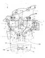
ここに,図1は,本発明の実施の形態に係る電気掃除機Xの外観図,図2及び図3は,本発明の実施の形態に係るサイクロン集塵装置Yの内部構造を説明するための断面図,図4は,本発明の実施の形態に係るサイクロン集塵装置Yに設けられた螺旋状回転圧縮部を説明するための図((a)は,下方から見た斜視図,(b)は,上方から見た斜視図),図5は,本発明の実施の形態に係るサイクロン集塵装置Yに設けられた上部フィルタユニット13を説明するための図,図6は,本発明の実施の形態に係るサイクロン集塵装置Yの内部構造を螺旋状回転圧縮部を中心として説明するための断面図,図7は,本発明の実施の形態に係るサイクロン集塵装置Yの内部構造を説明するための分解斜視図,図8は,本発明の実施の形態に係るサイクロン集塵装置Yの螺旋状回転圧縮部への回転力伝達経路を説明するための断面図,図9は,螺旋状回転圧縮部の回転によって,塵埃が圧縮・積層される状況を説明するサイクロン集塵装置Yの断面図,図10は,回転抑制手段の取付位置を説明するための集塵容器部分の断面図,図11は,本発明の実施形態にかかるサイクロン集塵装置Yの制御装置を示すブロック図,図12は,本発明の実施形態にかかるサイクロン集塵装置Yの制御装置に処理手順を示すフローチャート,図13は,駆動部の電流変化を示すグラフである。
Hereinafter, embodiments of the present invention will be described with reference to the accompanying drawings so that the present invention can be understood. The following embodiment is an example embodying the present invention, and does not limit the technical scope of the present invention.
Here, FIG. 1 is an external view of the vacuum cleaner X according to the embodiment of the present invention, and FIGS. 2 and 3 are for explaining the internal structure of the cyclone dust collecting apparatus Y according to the embodiment of the present invention. FIG. 4 is a cross-sectional view of FIG. 4A and FIG. 4B are diagrams for explaining the helical rotary compression unit provided in the cyclone dust collecting apparatus Y according to the embodiment of the present invention. b) is a perspective view seen from above), FIG. 5 is a view for explaining the
まず,図1を用いて,本発明の実施の形態に係る電気掃除機Xの概略構成について説明する。
図1に示すように,前記電気掃除機Xは,掃除機本体部1,吸気口部2,接続管3,接続ホース4,操作ハンドル5などを備えて概略構成されている。前記掃除機本体部1には,電動送風機221,サイクロン集塵装置Y,制御装置Zなどが内蔵されている。なお,前記サイクロン集塵装置Yについては後段で詳述する。
前記電動送風機221は,吸気を行うための送風ファン及び該送風ファンを回転駆動する送風駆動モータを有している。前記制御装置Zの詳細は,図11を参照して追って説明されるが,制御装置Zは,CPUやRAM,ROMなどの制御機器を有してなり,前記電気掃除機Xを統括的に制御する。具体的には,前記制御装置Zでは,前記CPUが前記ROMに記憶された制御プログラムに従って,本発明の対象である圧縮部材の回転制御を含む各種の処理を実行する。
なお,前記操作ハンドル5には,ユーザが前記電気掃除機Xの稼働の有無や運転モードの選択操作などを行うための操作スイッチ(不図示)が設けられている。また,その操作スイッチの近傍には,前記電気掃除機Xの現在の状態を表示するLEDなどの表示部(不図示)も設けられている。
First, the schematic configuration of the electric vacuum cleaner X according to the embodiment of the present invention will be described with reference to FIG.
As shown in FIG. 1, the electric vacuum cleaner X is schematically configured to include a vacuum cleaner
The
The operation handle 5 is provided with an operation switch (not shown) for allowing the user to operate the vacuum cleaner X and to select an operation mode. A display unit (not shown) such as an LED for displaying the current state of the electric vacuum cleaner X is also provided in the vicinity of the operation switch.
前記掃除機本体部1は,該掃除機本体部1の前端に接続された前記接続ホース4と,該接続ホース4に接続された前記接続管3とを介して前記吸気口部2に接続されている。
従って,前記電気掃除機Xでは,前記掃除機本体部1に内蔵された前記電動送風機221が作動されることにより,前記吸気口部2からの吸気が行われる。そして,前記吸気口部2から吸気された空気は,前記接続管3及び前記接続ホース4を通じて前記サイクロン集塵装置Yに流入する。前記サイクロン集塵装置Yでは,吸い込まれた空気から塵埃が遠心分離される。前記サイクロン集塵装置Yで塵埃が分離された後の空気は,前記掃除機本体部1の後端に設けられた不図示の排気口から排気される。
The
Accordingly, in the electric vacuum cleaner X, the
以下,図2〜6を参照しつつ,本発明に係るサイクロン集塵装置の一例であるサイクロン集塵装置Yについて詳説する。サイクロン集塵装置は,本発明の実施形態に係るサイクロン分離装置の一例であり,捕集対象物が塵埃である場合である。
図2及び図3に示すように,前記サイクロン集塵装置Yは,筐体10,内周面が略円筒状で,上記筐体10に対して着脱自在の集塵容器11(捕集容器の一例),内筒12,上部フィルタユニット13,塵埃受部14及び除塵駆動機構15などを備えて概略構成されている。除塵駆動機構15は,本発明の構成要素である後述のモータなどの圧縮部材駆動手段を含んでいる。
前記サイクロン集塵装置Yでは,前記集塵容器11,前記内筒12,前記上部フィルタユニット13,及び前記塵埃受部14が,垂直の中心軸Pを中心に同軸状に配置されている。また,前記サイクロン集塵装置Yは,前記掃除機本体部1に着脱可能に構成されている。
上記筐体10は,フィルタ122を備えた内筒12を備えている。
このサイクロン集塵装置Yでは,略円筒状の集塵容器11の中心部に設けられた前記内筒12から前記集塵容器11内の空気を排気することにより,前記集塵容器11の円周部に設けられた空気流入口111a(図7参照)から吸い込まれた空気を集塵容器11の内周面に沿って旋回させた後,前記上部フィルタユニット13などを経て前記内筒12を経て排気し,前記空気に含まれる比較的大きい捕集対象物を前記集塵容器11の底部で捕集すると共に,比較的小さい捕集対象物を前記上部フィルタユニット13などにおいて捕集するものである。
Hereinafter, the cyclone dust collector Y which is an example of the cyclone dust collector according to the present invention will be described in detail with reference to FIGS. The cyclone dust collecting apparatus is an example of a cyclone separating apparatus according to an embodiment of the present invention, and is a case where the collection target is dust.
As shown in FIGS. 2 and 3, the cyclone dust collector Y has a
In the cyclone dust collecting apparatus Y, the
The
In the cyclone dust collecting apparatus Y, the air in the
前記集塵容器11は,吸い込まれた空気から分離された塵埃を収容するための内周面が円筒状で,且つ外形も円筒状の容器である。前記集塵容器11は,前記サイクロン集塵装置Yの筐体10に着脱可能に構成されている。ユーザは,前記掃除機本体部1から前記サイクロン集塵装置Yを取り出した後,該サイクロン集塵装置Yから前記集塵容器11を取り外して,該集塵容器11内の塵埃を廃棄する。なお,前記サイクロン集塵装置Yの筐体10と前記集塵容器11との間には,環状のシール部材161が設けられている。このシール部材161により,前記筐体10及び前記集塵容器11の間の空気の漏れが防止される。
集塵容器11の内面には,後述の圧縮部材の回転に伴って該圧縮部材に押されて回転しようとする前記捕集容器11内面に蓄積された塵埃の回転を抑制する後述の回転抑制手段が形成されている。詳細は追って述べる。
また,前記集塵容器11の底部には,前記内筒12に設けられた後述の回転軸部123bに嵌合する嵌合部11aが設けられている。前記嵌合部11aの外周部には,前記内筒12の回転軸部123bとの隙間を埋めるための環状のシール部材11bが設けられている。このシール部材11bにより,前記回転軸部123b及び前記集塵容器11の間の空気の漏れが防止される。
The
On the inner surface of the
Further, a
さらに,前記集塵容器11には,前記接続ホース4(図1参照)が接続される接続部111が設けられている。前記吸気口部2から前記接続管3及び前記接続ホース4を通じて吸い込まれた空気は,前記接続部111から前記集塵容器11内に流入する。
ここで,前記接続部111の前記集塵容器11への空気流入口(不図示)は,前記接続ホース4からの空気が前記集塵容器11内で旋回するように形成されている。具体的に,前記空気流入口(不図示)は,前記集塵容器11側の出口が該集塵容器11の円周方向に向くように形成されている。
従って,前記集塵容器11では,吸い込まれた空気を旋回させることで該空気に含まれた比較的大きい塵埃が遠心力によって分離(遠心分離)される。そして,前記集塵容器11で遠心分離された塵埃は,該集塵容器11の底部に蓄積される(図2,3の塵埃D1)。
一方,塵埃が分離された後の空気は,前記集塵容器11から矢印(図2)で示す排気経路112に沿って前記掃除機本体部1に設けられた不図示の排気口から外部に排気される。ここで,前記集塵容器11から前記排気口(不図示)までの前記排気経路112上には,前記内筒12,前記塵埃受部14,及び前記上部フィルタユニット13が順に配置されている。
Further, the
Here, the air inlet (not shown) of the connecting
Therefore, in the
On the other hand, the air after the dust has been separated is exhausted from the
前記内筒12は,前記集塵容器11内に配置された円筒状の部材である。ここで,前記内筒12は,前記塵埃受部14によって回転可能に支持されている。具体的に,前記内筒12は,該内筒12の上端に設けられた環状の凹部12aが,前記塵埃受部14の下端に設けられた環状の支持部14cに支持されることにより回転可能な状態で吊り下げられている。なお,前記内筒12を回転可能に支持する構成は,これに限られるものではない。例えば,前記内筒12の上下の端部を軸支することが一例として考えられる。
さらに,前記内筒12の上端には,後述の傾斜除塵部材134に設けられた係合部134cに係合する複数の連結部12bが設けられている。前記連結部12bは,前記内筒12の上端の開口縁部に上方に突出して設けられたリブである。
前記内筒12は,前記連結部12b及び前記係合部134cの係合によって,前記傾斜除塵部材134に一体回転可能に連結されている。これにより,前記内筒12は,前記傾斜除塵部材134に連動して回転することになる。なお,前記内筒12及び前記傾斜除塵部材134の連結構造はこれに限られない。例えば,前記内筒12及び前記傾斜除塵部材134各々に設けられた嵌合部を嵌合させることにより一体回転可能に連結する構成が考えられる。
The
Furthermore, a plurality of connecting
The
また,前記内筒12の上部には,前記集塵容器11で塵埃が分離された後の空気を,前記上部フィルタユニット13に向けて排気するための内筒排気口121が形成されている。そして,前記内筒排気口121には,該内筒排気口121全体を覆う円筒状を成す内筒フィルタ122が設けられている。前記内筒フィルタ122は,前記内筒排気口121を通過する空気を濾過する。
例えば,前記内筒フィルタ122は,メッシュ状のエアフィルタ等である。なお,前記内筒フィルタ122は,前記内筒排気口121の内側又は外側のいずれに設けられていてもよい。また,前記排気口121及び前記内筒フィルタ122に換えて,前記内筒12にメッシュ状の孔を形成する構成も考えられる。その場合は,そのメッシュ状の孔が前記内筒排気口121及び前記内筒フィルタ122として機能する。
Further, an inner
For example, the
一方,前記内筒12の下部には,前記集塵容器11内の塵埃を圧縮するための螺旋状回転圧縮部123が設けられている。
前記螺旋状回転圧縮部123の斜視図である図4を参照しつつ,前記螺旋状回転圧縮部123について説明する。
図2〜4に示されているように,前記螺旋状回転圧縮部123には,螺旋部123a,回転軸部123b,円盤状遮蔽部材123cが設けられている。
前記回転軸部123bは,前記集塵容器11の底部に設けられた前記嵌合部11aに嵌合される中空円筒である。前述したように,前記回転軸部123b及び前記嵌合部11aの間には前記シール部材11b(図2,3参照)が介在する。
On the other hand, a spiral
With reference to FIG. 4, which is a perspective view of the helical
As shown in FIGS. 2 to 4, the spiral
The
円盤状遮蔽部材123cは,前記集塵容器11内において,後述する旋回流の遠心分離力により塵埃を分離する上側空間の部分(分離部104)と,塵埃を蓄積する下側空間の部分(集塵部105)との仕切りの役割を果たす。これにより,捕集した塵埃が巻き上がり,内筒フィルタ122を詰まらせる不都合を防ぐ。また,円盤状であるため,サイクロン気流中に含まれる塵埃が引っかかることが無く,塵埃を効率的に集塵容器11の底部へ誘導することができる。
The disk-shaped
また,前記回転軸部123bには,該回転軸部123bを中心にして,前記集塵部105の底面に向かって螺旋状に延び,その上下面が,前記垂直中心軸Pを中心とする螺旋状曲面を備えて湾曲した板状の螺旋部123a(本発明の圧縮部材の一例)が設けられている。前記螺旋部123aは,後述するように前記内筒12が回転されるとき,前記集塵容器11内に蓄積された塵埃を集塵容器11の底部向かって移動させる。この時,前記螺旋上部123aの前記螺旋状曲面が,該螺旋状曲面を螺子と想定したときに,該圧縮部材の回転により螺子が後退するように形成されていることにより,この螺旋状曲面で塵埃を押しつぶし,圧縮することができる。
さらに,前記内筒12が回転されるとき,前記螺旋状部123aの「螺子の運び作用」によって,集塵容器11の底部まで移動した塵埃に対して前記螺旋部123aは,前記集塵容器11の底部との摩擦によって,上記底面との間で塵埃を回転により回転軸中心から外側に向かって押し出し圧縮することになる。このような構成によれば,塵埃が回転によって固く圧縮されるので,前記集塵容器11の塵埃の蓄積可能量を増加させることができる。従って,例えば前記集塵容器11の小型化を実現することが可能である。また,固く圧縮された塵埃は,容易に解けないので,取り出し時にも空気中に飛散する問題がなく,そのままの形で塵埃として廃棄することが出来る。
Further, the
Further, when the
一方,前記内筒12の内筒フィルタ122で濾過された後の空気は,該内筒12内を通じて前記上部フィルタユニット13に導かれる。
ここで,図2及び図3に加えて図5を参照しつつ,前記上部フィルタユニット13について説明する。ここに,図5(a)は,前記上部フィルタユニット13を上方から見た斜視図,図5(b)は,前記上部フィルタユニット13を下方から見た斜視図である。
前記上部フィルタユニット13は,HEPAフィルタ(High Efficiency Particulate Air Filter)131,フィルタ除塵部材132及び傾斜除塵部材134などを有している。
On the other hand, the air after being filtered by the
Here, the
The
前記HEPAフィルタ131は,前記内筒12から排気されて前記排気経路112上を流れる空気をさらに濾過するエアフィルタの一種である。
前記HEPAフィルタ131は,前記垂直中心軸Pの周りに環状に配置固定された複数枚のフィルタの集合で構成されている。なお,複数枚のフィルタ各々は,例えば図5(b)に示すような骨組みに固定される。また,前記HEPAフィルタ131に含まれた複数枚のフィルタは,略水平方向に凹凸を繰り返すプリーツ状に配置されている。これにより,前記HEPAフィルタ131におけるフィルタ面積が十分に確保されている。なお,前記HEPAフィルタ131の下端と前記筐体10との間には,環状のシール部材162が設けられている。これにより,前記HEPAフィルタ131と前記筐体10との間の空気の漏れが防止される。
また,図2及び図3に示すように,前記HEPAフィルタ131の中央には,後述のフィルタ除塵部材132に設けられた連結部133が嵌挿される中空部131aが形成されている。また,前記中空部131aには,前記連結部133を回転可能に支持する支持部131bが設けられている。
The
The
As shown in FIGS. 2 and 3, a
前述したように,前記サイクロン集塵装置Yでは,前記内筒フィルタ122及び前記HEPAフィルタ131の二段階で空気を濾過することにより塵埃の捕集力が高められている。
但し,前記HEPAフィルタ131に塵埃が堆積して目詰まりが生じると,空気の通過抵抗が大きくなる。そのため,前記電動送風機221の負荷が大きくなり吸塵力が低下するおそれがある。そこで,前記上部フィルタユニット13には,前記HEPAフィルタ131に付着した塵埃を除去する前記フィルタ除塵部材132が設けられている。
As described above, in the cyclone dust collector Y, the dust collecting power is enhanced by filtering the air in two stages of the
However, if dust accumulates on the
前記フィルタ除塵部材132は,前記HEPAフィルタ131の中央部に設けられた前記支持部131bによって回転可能に支持されている。具体的に,前記フィルタ除塵部材132には,前記支持部131bに回転可能に支持される連結部材133が設けられている。
また,前記連結部133には,該連結部133に設けられたネジ穴133aに前記傾斜除塵部材134がネジ133bで螺着される。これにより,前記フィルタ除塵部材132及び前記傾斜除塵部材134が一体回転可能に連結される。なお,前記傾斜除塵部材134及び前記HEPAフィルタ131の間には,隙間を埋める環状のシール部材163が設けられている。これにより,前記傾斜除塵部材134及び前記HEPAフィルタ131の間の空気の漏れが防止される。
The filter
In addition, the inclined
前記フィルタ除塵部材132は,図2及び図5(a)に示すように,前記HEPAフィルタ131の上端部に接触するように該HEPAフィルタ131に沿って所定間隔で配置された二つの接触部132aを有している。前記接触部132aは板バネ状の弾性部材である。なお,前記接触部132aは,板バネ状の弾性部材に限られるものではない。また,前記接触部132aは,一つであっても或いはさらに複数であってもよい。
そして,前記フィルタ除塵部材132には,その外周部にギア132bが形成されている。このギア132bは,図2及び図3に示すように,前記サイクロン集塵装置Yに設けられた除塵駆動機構15に設けられたギア15aに噛合される。
As shown in FIGS. 2 and 5A, the filter
The filter
ここに,前記除塵駆動機構15は,図2に明らかな如く,前記掃除機本体部1側に設けられた不図示の除塵駆動モータ(圧縮部材駆動手段の一例)に連結される減速器及び該減速器に連結されたギア15aを有している。前記除塵駆動機構15では,前記除塵駆動モータの回転力が前記減速器を介して前記ギア15aに伝達される。そして,前記除塵駆動機構15のギア15aの回転力は,前記ギア132bに伝達される。これにより,前記フィルタ除塵部材132が回転される。
そして,上記フィルタ除塵部材132の回転は,前記したように,傾斜除塵部材134に伝達され,傾斜除塵部材134と一体に回転する内筒12及び内筒12と一体の螺旋状回転圧縮部123が前記垂直中心軸Pの周りに回転する。
なお,本実施の形態では,前記除塵駆動モータによって前記フィルタ除塵部材132が回転される場合を例に挙げて説明するが,前記除塵駆動モータに換えて,前記フィルタ除塵部材132を手動で回転させることのできる機構を設けることも他の実施例として考えられる。
さらに,除塵駆動モータ以外の別のモータによって,螺旋状回転圧縮部123を回転させることも当然考えられる。上部フィルタユニット13の除塵と,螺旋状回転圧縮部123の回転とを別に行いたい場合には,このような別駆動の方を採用することも考えられる。
As shown in FIG. 2, the dust
The rotation of the filter
In the present embodiment, the case where the filter
Further, it is naturally conceivable to rotate the helical
前記フィルタ除塵部材132が回転されると,該フィルタ除塵部材132に設けられた二つの前記接触部132a各々は,プリーツ状に形成された前記HEPAフィルタ131に断続的に衝突して振動を与える。従って,前記HEPAフィルタ131に付着した塵埃は,前記フィルタ除塵部材132から与えられる振動によって叩き落とされる。なお,前記除塵駆動モータ(不図示)が作動されるタイミングは,例えば前記電気掃除機Xにおける集塵動作の開始前や終了後であることが望ましい。これにより,前記電動送風機221による吸気によって前記HEPAフィルタ131に下流側への気流がない状態で,前記HEPAフィルタ131の除塵を効果的に行うことができる。
When the filter
また,前述したように,前記塵埃受部14は,前記内筒12を回転可能に支持している。具体的に,前記塵埃受部14の開口14a縁部の下端には,前記内筒12の上端に設けられた環状の前記凹部12aに嵌合される環状の前記支持部14cが設けられている。これにより,前記内筒12は,前記塵埃受部14によって回転可能な状態で吊り下げられている。
As described above, the
次に,前記した螺旋状回転圧縮部123の構造についてさらに詳しく説明する。
前述したように,サイクロン集塵装置Yは,概略円筒形状に形成され,上部に配置された上部フィルタユニット13と,下部に配置された集塵容器11とを備えて構成されている。
集塵容器11内に収納された前記内筒12の下端には,分離部104と集塵部105の境界部である円盤状遮蔽部材123cが一体的に接合されている。上記円盤状遮蔽部材123cとその下部の前記螺旋部123aの外径は,ほぼ同じで,分離部104の内径より小さく,円盤状遮蔽部材123cの外周と集塵容器11の内壁との間には隙間(クリアランス)106(図6)が存在している。隙間(クリアランス)106は,分離部104において分離した塵埃を集塵部105へ移動する場合に,ある程度の体積を持つ塵埃においてもスムーズに移動することができ,かつ一度集塵部105に移動・蓄積した塵埃を巻き上げ,内筒フィルタ122を詰まらさないようにするに適した値である。実験によれば13mm程度が望ましいことが分かった。
Next, the structure of the helical
As described above, the cyclone dust collector Y is formed in a substantially cylindrical shape, and includes the
A disc-shaped
前記集塵容器11の内面には,図10に明示のような前記螺旋部123aの回転に伴って該螺旋部123aに押されて回転しようとする前記集塵容器11内面に蓄積された塵埃の回転を抑制する回転抑制手段53,54が設けられている。この回転抑制手段53,54はいずれか一方でも,或いは両方でもよいが,集塵容器11の底面側に設けられる回転抑制手段53は必須である。
但し,底面側の回転抑制手段53だけでは,塵埃の大きいかたまりに対して回転を抑制することができないので,側面側の背の高い回転抑制手段54も必要である。
前記回転抑制手段53,54は,前記集塵容器11の内面の一部について他の部分と較べて捕集対象物である塵埃に対する摩擦係数を変化させるものが採用される。
具体的な前記回転抑制手段53,54の一例は,前記捕集容器内面の一部に貼り付けられたゴム片であっても良い。
或いは,前記回転抑制手段53,54は,前記集塵容器11の内面の一部の内面に形成された凹凸形状であってもよい。例えば,前記集塵容器11の内面の一部に,おろし板状のギザギザが形成されており,これによって集塵容器11の内面に堆積した塵埃が引っかかって,前記螺旋部123aが回転することで塵埃が押されて回転しようとするのを抑制する。この回転抑制手段53,54によって塵埃が集塵容器11の内面に固定される傾向が強くなり,前記螺旋部123aに塵埃が押しつぶされて,塵埃の圧縮が更に促進される。
このように回転抑制手段53,54は,塵埃の圧縮に寄与するものであるが,さらに後述するように,集塵容器11内に蓄積された塵埃の量を正確に検知するためにも役立つが,この機能については追って説明する
On the inner surface of the
However, since only the rotation suppression means 53 on the bottom surface side cannot suppress rotation against a large lump of dust, a tall rotation suppression means 54 on the side surface side is also necessary.
As the rotation suppressing means 53, 54, a part of the inner surface of the
A specific example of the rotation suppression means 53, 54 may be a rubber piece attached to a part of the inner surface of the collection container.
Alternatively, the rotation suppressing means 53 and 54 may have an uneven shape formed on a part of the inner surface of the
As described above, the rotation suppressing means 53 and 54 contribute to the compression of the dust. However, as will be described later, the rotation suppressing means 53 and 54 are useful for accurately detecting the amount of the dust accumulated in the
さらにまた,上記螺旋部123aと集塵容器11内面との間の隙間(クリアランス)107は,集塵容器11の径が集塵容器11の底部に向かい小さくなる部分であるため,集塵容器11の底部に向かって小さくなるように構成されている。これにより,塵埃と集塵容器11の内壁側面との摩擦が大きくなり,螺旋状回転圧縮部123による中心軸P方向に塵埃を移動させる力が大きくなるため,されに効率的に圧縮が行なわれる。
Furthermore, since the clearance (clearance) 107 between the
また,円盤状遮蔽部材123cは,高さ方向に所定の厚みを持つ。円盤状遮蔽部材123cの高さ方向の厚みは,分離部104における遠心分離性能に影響し,本実施例では,実験により求めた13mm程度としている。
The disc-shaped
また,螺旋状回転圧縮部123の螺旋部123aは,前記したように上下の螺旋状曲面に挟まれて湾曲した板状に形成されており,円盤状遮蔽部材123cから下方に向かってほぼ垂直に伸びる回転軸部123bを中心にして,集塵容器11の底面に向かって始端(円盤状遮蔽部材123cとの接続部)から終端(下端)までが1周分以上,回転軸部123bの周囲に巻き付くように形成されている。上記巻き付き角度の望ましい数字としては,1.6周分である。このような巻き付きによって,螺旋部123aは,集塵容器11の内周面にそったサイクロン旋回気流(図6に矢印Aで示す)の回転方向に沿って下方に向かって傾斜する螺旋状の旋回面が形成されている。
Further, as described above, the
また,螺旋状回転圧縮部123の螺旋部123aの終端(下端)と集塵部105の底面との間には,隙間(クリアランス)108(図6参照)が介在している。これにより,回転軸中心から外側に向け押し出し,圧縮することが出来る塵埃量を大幅に増加することが出来る。
Further, a gap (clearance) 108 (see FIG. 6) is interposed between the terminal end (lower end) of the
以上のように構成された電気掃除機の動作について以下に説明する。
図3,図6に示すように,分離部104の周方向に形成された接続部111の空気流入口111aから集塵容器11の分離部104に入った気流は,図6の矢印Aのように,分離部104の円筒状の内周面に沿って高速で旋回する。旋回気流中の比較的大きい塵埃には遠心力が作用して気流から分離され,集塵容器11の内壁へ押し付けられる。図2に示すように,空気の排気口121が,下方にあるため,その後,気流は旋回しながら,集塵部105に入る。図6において二点鎖線で示す矢印Aのように旋回する気流(主流)は,集塵部105の底面に到達した後は上昇に転じる。図6の例では,この螺旋状回転圧縮部123のまわりの間隙107を旋回する気流の回転方向と螺旋状回転圧縮部123の螺旋部123aの傾き方向が一致しており,サイクロン旋回気流を妨げることがない。このため,圧力損失が少なく効率的な遠心分離が可能であり,高い吸い込み仕事率が得られる。
The operation of the vacuum cleaner configured as described above will be described below.
As shown in FIGS. 3 and 6, the airflow that enters the
また,図6に二点鎖線で示す矢印Aの気流により運ばれる塵埃は,螺旋部123aの終端部(下端部)と集塵容器11の底面との間の空間112aに引っかかり(トラップされ),蓄積され,螺旋部123aの螺旋形状の湾曲面に沿って下側から順に積層されていく。このため,さらに圧力損失の増加を防ぐことができる。
In addition, the dust carried by the air flow indicated by the two-dot chain line in FIG. 6 is trapped in the space 112a between the terminal end (lower end) of the
さらに,螺旋状回転圧縮部123のまわりの間隙107を旋回する気流の回転方向と螺旋状回転圧縮部123の螺旋部123aの傾き方向が一致しているため,蓄積・積層された塵埃は,気流によっても若干圧縮される。これにより,蓄積・積層された塵埃の容積が小さくなり,より効率的な塵埃捕集を達成できる。
Furthermore, since the rotational direction of the airflow swirling through the
次に,塵埃の空気流による蓄積と積層の作用について説明する。
前述したように,吸引された塵埃は,分離部104において分離され,隙間106(図6)を通り,集塵部105へ導かれる。集塵部105においては,塵埃は隙間107を通り,隙間108によりせき止められる(トラップされる)ことにより,蓄積される。この蓄積は,螺旋状回転圧縮部123が回転されるごとに既に蓄積された塵埃の上に積層されていく。そのため,この集塵装置では,螺旋部123aに沿って,偏ることなく積層が成長していくため,集塵部105内で偏って蓄積されていくことがなく,同容積の集塵部と比較して集塵可能容量が飛躍的に向上する。
また,螺旋部123aは,サイクロン旋回気流の回転方向に沿って下方に向かって傾斜する方向性をもつ螺旋形状とすることが出来る。この場合には,サイクロンの気流による圧縮効果も得られる。これにより,さらに集塵可能容量が向上する。
Next, the accumulation of dust by the air flow and the action of stacking will be described.
As described above, the sucked dust is separated at the
Moreover, the
次に,回転圧縮の作用について具体的に説明する。
たとえば,送風駆動モータの駆動が停止されると,気流が旋回を止める。送風駆動モータの駆動停止が確認された後,除塵駆動機構15が駆動されると,上述したように内筒12,排気口121,円盤状遮蔽部材123c,螺旋状回転圧縮部123,回転軸部123bが一体となって,垂直中心軸Pを中心として,図8の矢印D方向(上面から見て,反時計方向)に回転する。このようにして,除塵駆動機構15による回転が,図8に示される第1の回転軸線152と第2の回転軸線153を介して回転軸部123bに伝達される。
こうして螺旋状回転圧縮部123が回転すると,螺子の原理により,回転軸方向(図9の矢印Eで示す垂直下向き方向)に推力が発生する。この推力により,集塵部105に蓄積されている図9の塵埃200は,回転軸方向に押し出され,集塵容器11の底面に押し付けられることにより回転軸方向に圧縮される。
Next, the action of rotational compression will be specifically described.
For example, when the drive of the blower drive motor is stopped, the airflow stops turning. When the dust
When the helical
ところで,サイクロン集塵装置Yでは,塵埃が図10における300(ほぼ螺旋部123aの始端の位置)よりも上部まで積層された場合,上側から新たに塵埃201(図9参照)が吸引されて来ても,塵埃201は引っかかる部分がないため積層・集積することができず,内筒12の回りを回転し続けてしまう。回転し続けることにより,内筒フィルタ122に大量の塵埃が付着し,吸引力が急激に低下する。また,送風駆動モータに大きな負担がかかり,製品寿命を低下させる。
By the way, in the cyclone dust collector Y, when dust is stacked up to the upper part of 300 in FIG. 10 (substantially the position of the starting end of the
しかしながら,この集塵装置Yでは,螺旋部123aの回転によって集塵容器の底面との間に蓄積した塵埃に回転を与え,これによって軸中心から外側に向かって押し出すことで圧縮するので,螺旋状回転圧縮部123と集塵容器11の底部との間の塵埃200は,一度圧縮されると,回転停止後,さらには,集塵容器11を解放して圧縮力が解除された後も,圧縮状態が保持される。
However, in this dust collector Y, the
前記したように螺旋状回転圧縮部123が回転することで,集塵容器11の内面に蓄積した塵埃が硬く圧縮されるので,集塵容器11内に多くの塵埃を蓄積することができ,また,集塵容器11から塵埃を捨てる時に,塵埃が空気中に飛散しないので,衛生的であるが,集塵容器11内に蓄積された塵埃の量があまりに多くなると,螺旋状回転圧縮部123を回転駆動させるための圧縮部材駆動手段としての除塵駆動モータに過負荷がかかる可能性がある。
そのため,除塵駆動モータが過負荷となる前に停止させ,或いはそれより更に以前に過負荷の可能性があることを使用者に警告するような表示をすることが望ましい。但し,除塵駆動モータ自体の負荷は,徐々に増加するものではなく,ある量を超えると急激に増加する傾向があるため,事前に察知することが難しい。
そこで本発明者は,鋭意研究したところ,前記駆動モータの電流値の変化と駆動モータの負荷との間に関係があることを理解するに至った。
図12は,前記集塵容器11底部の一部分に摩擦係数の高い部分を作ったり,塵埃が引っかかるぎざぎざを作った集塵容器11を用いて,塵埃の蓄積と圧縮動作を行った場合の上記駆動モータの電流測定値の変化を示すグラフである。縦軸が電流値,横軸が時間である。
例1の波形は収納された塵埃の量が少ないときの例であり平均電流Aaの値が小さく,電流うねりの振幅Saも小さい。また電流変動の周期Taは短い。これは圧縮が少なく圧縮駆動部の負荷が小さく回転遅れを生じていないためである。
一方,例2は収納された塵埃の量が多いときの例であり,平均電流Abや電流うねりの振幅Sbが大きくなっている。また圧縮時の負荷が大きくなり圧縮体1駆動部が回転遅れを生じるため周期Tbが長くなっている。
このような蓄積された塵埃の量に応じて平均電流Abや電流うねりの振幅Sb,あるいはうねりの周期Tbが変化するという現象から,本発明者は,これらの電気量を電流検知部227(本発明の電流検知手段の一例)で検知することで,蓄積された塵埃の量を間接的に検出することができることに気がついたのであり,本発明は,このような知見に基づいて創作されたものである。即ち上記のような駆動モータ(圧縮部材駆動手段の一例)の電流値に関するデータを予め定めた所定の閾値と比較し,その比較結果に応じて,警告や集塵機の停止処理をすることで駆動モータの過負荷を防止することができる。
As described above, the rotation of the helical
For this reason, it is desirable to stop the dust removal drive motor before it is overloaded, or to display a warning to the user that there is a possibility of overload before that. However, the load of the dust removal drive motor itself does not increase gradually, but it tends to increase rapidly when it exceeds a certain amount, so it is difficult to detect in advance.
Therefore, the present inventor has conducted extensive research and has come to understand that there is a relationship between the change in the current value of the drive motor and the load of the drive motor.
FIG. 12 shows the above driving in the case where dust is accumulated and compressed using the
The waveform of Example 1 is an example when the amount of stored dust is small. The value of the average current Aa is small, and the amplitude of the current swell is also small. Moreover, the period Ta of the current fluctuation is short. This is because there is little compression and the load on the compression drive unit is small and no rotation delay occurs.
On the other hand, Example 2 is an example when the amount of stored dust is large, and the average current Ab and the amplitude Sb of the current swell are large. In addition, since the load at the time of compression is increased and the
From the phenomenon that the average current Ab, the current swell amplitude Sb, or the swell period Tb changes in accordance with the amount of accumulated dust, the present inventor has determined the amount of electricity as a current detector 227 (this It was noticed that the amount of accumulated dust could be indirectly detected by detecting with an example of the current detecting means of the invention, and the present invention was created based on such knowledge. It is. In other words, the drive motor (an example of the compression member driving means) as described above is compared with data relating to the current value determined in advance, and the drive motor is subjected to warning or dust collector stop processing according to the comparison result. Overload can be prevented.
具体的には,上記電流検知手段駆動モータの電流値に関する閾値として予め定められた第1の閾値を前記制御回路220内の記憶部(電流値記憶手段の一例,図11参照)に記憶しておき,電流検知部227による電流の検知結果が前記制御回路220内の記憶部に記憶された前記第1の閾値を超えた場合に,前記制御装置Zが,表示部224やブザー部225を用いて,使用者に対して警報を発することで駆動モータの過負荷を防止することができる。
前記制御回路220内の記憶部が,更に,前記第1の閾値よりも大きい第2の閾値を予め記憶しており,電流検知部227による電流の検知結果が前記第2の閾値を超えた場合に,前記制御装置Zが,表示部224やブザー部225を用いて使用者に対して警報を発すると共に,当該サイクロン集塵装置の運転を停止することで駆動モータの過負荷を完全に防止しうるようにしてもよい。
Specifically, a first threshold value that is predetermined as a threshold value related to the current value of the current detection means driving motor is stored in a storage unit (an example of current value storage means, see FIG. 11) in the
The storage unit in the
前記電流の検知結果としては,周期的に変化する駆動モータの駆動電流値Aあるいはそれに基づく値(例えば平均値と言った統計値など),または駆動電流値の最大値と最小値との差の値S(電流のうねり)またはこれに基づく値が一例として考えられる。 The detection result of the current includes a drive current value A of the drive motor that changes periodically or a value based on the drive current value A (for example, a statistical value such as an average value), or a difference between the maximum value and the minimum value of the drive current value. The value S (current swell) or a value based on this can be considered as an example.
前記電流の検知結果の別の例として,周期的に変化する電流のピーク値間の周期Tあるいはこれに基づく値であってもよい。 Another example of the current detection result may be a period T between periodically changing current peak values or a value based thereon.
更に前記電流の検知結果の別の例として,前記電流検知手段の検知電流についての所定時間の平均値A又は検知電流の変動周期の1周期若しくは複数周期の平均値Aあるいはこれらの値に基づく値が考えられる。 Further, as another example of the detection result of the current, the average value A for a predetermined time for the detection current of the current detection means, the average value A for one period or a plurality of periods of the fluctuation period of the detection current, or a value based on these values Can be considered.
上記のような平均電流A,うねりSあるいはその周期Tを測定して,所定過負荷防止処理を行うための前記制御装置Zの構成を図11を参照して説明し,その後,図12のフローチャートを参照して上記制御装置Zが行う電流うなりの幅Sを検知して集塵機を制御する制御装置Zの処理手順について説明する。 The configuration of the control device Z for measuring the average current A, the swell S or the period T thereof as described above and performing a predetermined overload prevention process will be described with reference to FIG. 11, and then the flowchart of FIG. The processing procedure of the control device Z that controls the dust collector by detecting the current beat width S performed by the control device Z will be described with reference to FIG.
図11は制御部Zの概略ブロック図である。220は制御回路部であり,手元スイッチ206からの入力に応じて駆動回路部222を介して電動送風機221の制御を実施し,また各種の入力処理あるいは表示等の制御を行う。上記駆動回路部222は,制御回路部の指令に従って電動送風機221を駆動するとともに電動送風機221に流れる電流を検出して制御回路部220へ入力する。
223は電源部であり制御回路部220等へ電源を供給する。224は表示部であり運転状態あるいは異常時の表示等を行う。225はブザーであり異常時に警報を発する。226は前記螺旋状圧縮部123の駆動部であり,具体的には前記のように除塵駆動モータ等で構成され,前記螺旋状回転圧縮部123を回転させる。駆動部226の電流は電流検知部227で検知され,後述のようにこの電流値によって前記螺旋状圧縮部123の駆動部の電流を検知し,集塵容器11内における塵埃の溜まり状態を検知する。駆動部226が,本発明における圧縮部材駆動手段の一例である。
FIG. 11 is a schematic block diagram of the control unit Z. A
A
次に図11及び図12を参照して,前記制御部Zによるこの集塵装置における判断動作について説明する。
手元スイッチ206には運転スイッチ(強,中,弱等)及び停止スイッチがあり,通常は,その操作により制御回路部220に信号が入力されるとその信号に応じて制御装置Zは,電動送風機221を制御する。制御装置Zは,電動送風機221の運転中に周期的に駆動部226を回転させて,圧縮動作をし,掃除機の運転中に,後述の方法で塵埃量を検知することも可能である。また掃除機の運転が停止されたときに塵埃量を検知することも可能である。また,圧縮動作のみの操作も可能である。塵埃の検知は通電されているあらゆるタイミングで実施することができる。また,塵埃満杯を検知した後に警報を出したり電動送風機221の運転を停止したりする制御も可能である。
Next, with reference to FIG.11 and FIG.12, the determination operation | movement in this dust collector by the said control part Z is demonstrated.
The
次に図13のフローチャートを用いて,電動送風機221が停止後に圧縮動作と電流検知動作を行う手順を説明する。図中,N10,N20,…は,制御装置Zによる制御手順の番号である。
掃除機が運転されると,吸引された塵埃と空気が吸入部を通って集塵容器に入ってくる。前述のようにサイクロンの特性により塵埃のうち比較的大きいものは集塵容器11の底面に蓄積する。
図13に示すように,電動送風機221が停止後,駆動部226がONされ,螺旋状回転圧縮部123が時計方向に回転駆動され,集塵容器11内の塵埃が螺旋状回転圧縮部123の最下部に押される圧縮動作が行われる(N10でYes)。
集塵容器11の底面及び側面には,前記のように回転抑制手段53,54が設けられているので,螺旋状圧縮部123の最下部に押された塵埃は回転抑制手段53,54で回転にブレーキが掛けられる結果,この回転抑制手段53,54付近で急激に圧縮される。
その結果,螺旋状圧縮部123の最下部が上記回転制御部53,54に近づくと駆動モータの負荷が大きくなり電流Aあるいは電流うなり振幅Sが大きくなるとともに回転速度が遅くなり電流うなりの周期Tは長くなる。前記電流検知部227は,このような電流の変化を検知することができ,前記回転抑制手段53,54の存在により圧縮効果が高くなるとともに電流うなりSが大きくなり,このデータによって塵埃量検知を精度よく検知することが可能となった。この圧縮体2は塵埃収納部の底部あるいは壁面のどちらにあっても良いし両方にあっても良い。
圧縮動作時の検知電流の電流値のうなり幅がS,をあるいは電流うなり周期がT,あるいは平均電流がAが,予め設定された所定の閾値を超えた場合(図13では電流うねりSが所定の設定値1を超えた場合)(N20で設定値1以上),駆動部226の負荷が駆動部226にとって過負荷となる前の状態であると推定するが,上記うねり値Sが,上記設定値1(第1の閾値)以上であって,かつ上記設定値1より大きい設定値2(第2の閾値)以下(N30でNo)の場合,駆動モータを停止するほどではないが,かなりの塵埃が溜まっていると判断して,即ち,塵埃捨てタイミングと判断して表示部224にLED表示による,あるいはブザー部225によりブザー音等による報知を行う(N40)。また電流のうねりSが上記設定値1(第1の閾値)以上であって,かつ上記設定値1より大きい設定値2(第2の閾値)以上である(N30でYes)場合には,上記警報の出力と共に駆動モータを停止する(N50)ことで,駆動モータの過負荷を完全に防止する。
Next, a procedure for performing the compression operation and the current detection operation after the
When the vacuum cleaner is operated, the sucked dust and air enter the dust container through the suction part. As described above, relatively large dust among the dust accumulates on the bottom surface of the
As shown in FIG. 13, after the
Since the rotation suppressing means 53 and 54 are provided on the bottom surface and the side surface of the
As a result, when the lowermost portion of the
When the beat width of the current value of the detected current during the compression operation is S, the current beat cycle is T, or the average current is A exceeds a predetermined threshold value (in FIG. 13, the current undulation S is predetermined). If the
上記の例では,電流のうねりSを問題としたが,これは電流値そのものあるいは電流値の平均値,または電流変動の周期について,それぞれについて定めた設定値との比較を行っても良いことは明らかである。 In the above example, the current undulation S is considered as a problem. However, it is possible to compare the current value itself, the average value of the current values, or the period of the current fluctuation with the set value determined for each. it is obvious.
あるいは検知精度を高めた方法として上記3種類の検知データの2つあるいは3つの組み合わせにより,蓄積された塵埃の量を推定してもよい。
更に電動送風機221を動かし塵埃の吸引を行った後に同様に圧縮動作と電流検知を行い,上記と同様に電流値A,電流のうねり幅S,あるいはうねり周期Tが予め定められた所定の閾値を超えるかあるいはこれらの組み合わせにて圧縮限界と判断したときは圧縮動作を停止し,駆動モータの過負荷防止をはかってもよい。
Alternatively, as a method for improving detection accuracy, the amount of accumulated dust may be estimated by using two or three combinations of the three types of detection data.
Further, after the
10…筐体(分離装置本体)
11…集塵容器(捕集容器)
12…内筒
13…上部フィルタユニット
14…集塵受部
15…除塵駆動機構
104…分離部
105…集塵部
123…螺旋状回転圧縮部
123a…螺旋部(圧縮部)
123b…回転軸部
220…制御回路部
221…電動送風機
222…駆動回路部
226…駆動部
227…電流検知部
10 ... Case (separator main body)
11 ... Dust collection container (collection container)
DESCRIPTION OF
123b ... Rotating
Claims (9)
前記捕集容器内に,該捕集容器の垂直中心軸を中心とする螺旋状曲面を備え,前記垂直中心軸の周りに回転可能な圧縮部材と,
前記捕集容器の内面の一部に設けられ,前記捕集容器内面の一部について他の部分と較べて捕集対象物に対する摩擦係数を変化させることで前記圧縮部材の回転に伴って該圧縮部材に押されて回転しようとする前記捕集容器内面に蓄積された捕集対象物の回転を抑制する回転抑制手段と,
前記圧縮部材を前記垂直中心軸周りに回転駆動する圧縮部材駆動手段の電流を検知する電流検知手段と,
前記電流検知手段による電流の検知結果に基づいて,当該サイクロン分離装置を制御する制御手段とを備えてなるサイクロン分離装置。 An inner peripheral surface is provided with a substantially cylindrical collection container, and air sucked from an air inlet provided in the circumferential direction on the circumferential portion of the collection container is disposed along the substantially cylindrical inner peripheral surface. After swirling, the relatively large collection object contained in the air is collected at the bottom of the collection container and is relatively small by exhausting from the center of the collection container through the filter means. A cyclone separation device for collecting an object to be collected in the filter means,
A compression member having a spiral curved surface centered on the vertical central axis of the collection container in the collection container, and rotatable about the vertical central axis;
It is provided on a part of the inner surface of the collection container, and the compression member is rotated along with the rotation of the compression member by changing the friction coefficient with respect to the collection object with respect to a part of the inner surface of the collection container as compared with other parts. Rotation suppression means for suppressing rotation of the collection object accumulated on the inner surface of the collection container which is pushed by the member and is about to rotate;
Current detection means for detecting the current of the compression member driving means for rotating the compression member around the vertical central axis;
A cyclone separator comprising: control means for controlling the cyclone separator based on a current detection result by the current detector.
Priority Applications (2)
| Application Number | Priority Date | Filing Date | Title |
|---|---|---|---|
| JP2008174478A JP4589989B2 (en) | 2008-07-03 | 2008-07-03 | Cyclone separator |
| CN200910159465A CN101617929A (en) | 2008-07-03 | 2009-07-02 | Cyclone separation device |
Applications Claiming Priority (1)
| Application Number | Priority Date | Filing Date | Title |
|---|---|---|---|
| JP2008174478A JP4589989B2 (en) | 2008-07-03 | 2008-07-03 | Cyclone separator |
Publications (2)
| Publication Number | Publication Date |
|---|---|
| JP2010012410A JP2010012410A (en) | 2010-01-21 |
| JP4589989B2 true JP4589989B2 (en) | 2010-12-01 |
Family
ID=41511474
Family Applications (1)
| Application Number | Title | Priority Date | Filing Date |
|---|---|---|---|
| JP2008174478A Expired - Fee Related JP4589989B2 (en) | 2008-07-03 | 2008-07-03 | Cyclone separator |
Country Status (2)
| Country | Link |
|---|---|
| JP (1) | JP4589989B2 (en) |
| CN (1) | CN101617929A (en) |
Cited By (3)
| Publication number | Priority date | Publication date | Assignee | Title |
|---|---|---|---|---|
| KR20210148832A (en) | 2020-06-01 | 2021-12-08 | 엘지전자 주식회사 | Cleaner |
| KR20210148831A (en) | 2020-06-01 | 2021-12-08 | 엘지전자 주식회사 | Cleaner |
| KR20210148830A (en) | 2020-06-01 | 2021-12-08 | 엘지전자 주식회사 | Cleaner |
Families Citing this family (4)
| Publication number | Priority date | Publication date | Assignee | Title |
|---|---|---|---|---|
| JP5881558B2 (en) * | 2012-08-24 | 2016-03-09 | シャープ株式会社 | Electric vacuum cleaner |
| WO2020246730A1 (en) | 2019-06-05 | 2020-12-10 | 엘지전자 주식회사 | Vacuum cleaner |
| CN216724410U (en) * | 2020-02-03 | 2022-06-14 | 朱圣铉 | Dust collecting device of vacuum cleaner |
| KR102185964B1 (en) * | 2020-02-03 | 2020-12-03 | 주성현 | Dust collector of vacuum cleaner |
Citations (9)
| Publication number | Priority date | Publication date | Assignee | Title |
|---|---|---|---|---|
| JP2002192018A (en) * | 2000-12-27 | 2002-07-10 | Yoshikou:Kk | Cyclone |
| JP2003070698A (en) * | 2001-09-07 | 2003-03-11 | Toshiba Tec Corp | Electric vacuum cleaner |
| JP2003088485A (en) * | 2001-09-20 | 2003-03-25 | Sharp Corp | Vacuum cleaner |
| JP2004008550A (en) * | 2002-06-07 | 2004-01-15 | Matsushita Electric Ind Co Ltd | Vacuum cleaner |
| JP2004283344A (en) * | 2003-03-20 | 2004-10-14 | Toshiba Tec Corp | Vacuum cleaner and its operation method |
| JP2005013312A (en) * | 2003-06-24 | 2005-01-20 | Matsushita Electric Ind Co Ltd | Vacuum cleaner |
| JP2006116340A (en) * | 2005-12-14 | 2006-05-11 | Sharp Corp | Vacuum cleaner |
| JP2007222614A (en) * | 2006-02-24 | 2007-09-06 | Lg Electronics Inc | Dust collector and vacuum cleaner |
| JP2007313293A (en) * | 2006-05-23 | 2007-12-06 | Lg Electronics Inc | Vacuum cleaner and its control method |
Family Cites Families (2)
| Publication number | Priority date | Publication date | Assignee | Title |
|---|---|---|---|---|
| JPS54114366U (en) * | 1978-01-31 | 1979-08-11 | ||
| JPH04370030A (en) * | 1991-06-14 | 1992-12-22 | Kubota Corp | Dust-discharging structure of thresher |
-
2008
- 2008-07-03 JP JP2008174478A patent/JP4589989B2/en not_active Expired - Fee Related
-
2009
- 2009-07-02 CN CN200910159465A patent/CN101617929A/en active Pending
Patent Citations (9)
| Publication number | Priority date | Publication date | Assignee | Title |
|---|---|---|---|---|
| JP2002192018A (en) * | 2000-12-27 | 2002-07-10 | Yoshikou:Kk | Cyclone |
| JP2003070698A (en) * | 2001-09-07 | 2003-03-11 | Toshiba Tec Corp | Electric vacuum cleaner |
| JP2003088485A (en) * | 2001-09-20 | 2003-03-25 | Sharp Corp | Vacuum cleaner |
| JP2004008550A (en) * | 2002-06-07 | 2004-01-15 | Matsushita Electric Ind Co Ltd | Vacuum cleaner |
| JP2004283344A (en) * | 2003-03-20 | 2004-10-14 | Toshiba Tec Corp | Vacuum cleaner and its operation method |
| JP2005013312A (en) * | 2003-06-24 | 2005-01-20 | Matsushita Electric Ind Co Ltd | Vacuum cleaner |
| JP2006116340A (en) * | 2005-12-14 | 2006-05-11 | Sharp Corp | Vacuum cleaner |
| JP2007222614A (en) * | 2006-02-24 | 2007-09-06 | Lg Electronics Inc | Dust collector and vacuum cleaner |
| JP2007313293A (en) * | 2006-05-23 | 2007-12-06 | Lg Electronics Inc | Vacuum cleaner and its control method |
Cited By (3)
| Publication number | Priority date | Publication date | Assignee | Title |
|---|---|---|---|---|
| KR20210148832A (en) | 2020-06-01 | 2021-12-08 | 엘지전자 주식회사 | Cleaner |
| KR20210148831A (en) | 2020-06-01 | 2021-12-08 | 엘지전자 주식회사 | Cleaner |
| KR20210148830A (en) | 2020-06-01 | 2021-12-08 | 엘지전자 주식회사 | Cleaner |
Also Published As
| Publication number | Publication date |
|---|---|
| JP2010012410A (en) | 2010-01-21 |
| CN101617929A (en) | 2010-01-06 |
Similar Documents
| Publication | Publication Date | Title |
|---|---|---|
| JP4589989B2 (en) | Cyclone separator | |
| JP5237770B2 (en) | Cyclone separator | |
| JP4750164B2 (en) | Cyclone separator | |
| JP4798637B2 (en) | Dust collector and vacuum cleaner | |
| JP2010081968A (en) | Cyclone separator | |
| JP2010035771A (en) | Cyclone separator | |
| JP2010004909A (en) | Cyclone separator | |
| WO2009116611A1 (en) | Cyclone separation apparatus | |
| JP6867991B2 (en) | Vacuum cleaner | |
| JP4378420B2 (en) | Cyclone separator | |
| JP2009285415A (en) | Vacuum cleaner | |
| JP5031807B2 (en) | Cyclone separator | |
| JP5101457B2 (en) | Cyclone separator | |
| JP5177814B2 (en) | Dust collector and vacuum cleaner | |
| JP4856271B2 (en) | Cyclone separator | |
| JP4890621B2 (en) | Cyclone separator | |
| JP4871416B2 (en) | Cyclone separator | |
| JP5070127B2 (en) | Cyclone separator | |
| JP4478191B2 (en) | Cyclone separator | |
| JP4812901B2 (en) | Cyclone dust collector, vacuum cleaner | |
| JP5184428B2 (en) | Cyclone separator | |
| JP5122406B2 (en) | Cyclone separator | |
| JP2018008154A (en) | Vacuum cleaner | |
| JP5108972B2 (en) | Cyclone dust collector, vacuum cleaner | |
| JP7365484B2 (en) | vacuum cleaner |
Legal Events
| Date | Code | Title | Description |
|---|---|---|---|
| A131 | Notification of reasons for refusal |
Free format text: JAPANESE INTERMEDIATE CODE: A131 Effective date: 20100511 |
|
| A521 | Written amendment |
Free format text: JAPANESE INTERMEDIATE CODE: A523 Effective date: 20100702 |
|
| TRDD | Decision of grant or rejection written | ||
| A01 | Written decision to grant a patent or to grant a registration (utility model) |
Free format text: JAPANESE INTERMEDIATE CODE: A01 Effective date: 20100817 |
|
| A01 | Written decision to grant a patent or to grant a registration (utility model) |
Free format text: JAPANESE INTERMEDIATE CODE: A01 |
|
| A61 | First payment of annual fees (during grant procedure) |
Free format text: JAPANESE INTERMEDIATE CODE: A61 Effective date: 20100910 |
|
| R150 | Certificate of patent or registration of utility model |
Free format text: JAPANESE INTERMEDIATE CODE: R150 |
|
| FPAY | Renewal fee payment (event date is renewal date of database) |
Free format text: PAYMENT UNTIL: 20130917 Year of fee payment: 3 |
|
| LAPS | Cancellation because of no payment of annual fees |