JP4584395B2 - End covering member - Google Patents
End covering member Download PDFInfo
- Publication number
- JP4584395B2 JP4584395B2 JP2000053244A JP2000053244A JP4584395B2 JP 4584395 B2 JP4584395 B2 JP 4584395B2 JP 2000053244 A JP2000053244 A JP 2000053244A JP 2000053244 A JP2000053244 A JP 2000053244A JP 4584395 B2 JP4584395 B2 JP 4584395B2
- Authority
- JP
- Japan
- Prior art keywords
- diameter
- contact portion
- close contact
- covering member
- covering
- Prior art date
- Legal status (The legal status is an assumption and is not a legal conclusion. Google has not performed a legal analysis and makes no representation as to the accuracy of the status listed.)
- Expired - Fee Related
Links
Images
Landscapes
- Protection Of Pipes Against Damage, Friction, And Corrosion (AREA)
Description
【0001】
【産業上の利用分野】
本発明は端部被覆部材、さらに詳細には電線などの端部を気密に、かつ容易に被覆可能な端部被覆部材に関する。
【0002】
【従来技術および問題点】
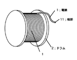
電線1などのライン状部材は、一般にドラム2に捲回されて保存されたり運搬されるのが一般的である。このようなライン状部材、たとえば電線1を使用した後、まだ余剰分があるときには、図9に示すように、同様にドラム2に捲回したまま、倉庫等に保管される。このとき、電線1の端部11は銅線などが露出した状態であり、特に銅線は錆び易いという欠点があるため、前記端部をテープなどで覆うことが行われている。
【0003】
しかしながら、上述の様なテープの端部を捲回して覆う作業は、若干の熟練を要し、手間がかかるという欠点があった。
【0004】
本発明は上述の問題点に鑑みなされたものであり、ライン状部材の端部を容易に気密に覆うことが可能な端部被覆部材を提供することを目的とする。
【0005】
【問題点を解決するための手段】
上記問題点を解決するため、本発明による端部被覆部材は、被覆すべき端部の径より大きな径の中空部を有する筒状の被覆体と、この被覆体の開口端に接続され被覆すべき端部の径より小さな径の中空部を有する密着部と、を備え、前記被覆体と前記密着部とはエラストマー材料によって一体的に形成されており、前記密着部はその先端に前記被覆体の外壁に当接して前記密着部と前記被覆体との間に空間を形成するための突起を有し、前記密着部は外側方向に捲り上げられており、前記密着部が捲り上げられた状態において前記被覆体の開口端は他部材又はその他の拡径手段によって拡径されることなく前記被覆すべき端部の径よりも大きい内径を有する、ことを特徴とする。
【0008】
本発明によれば、密着部は、好ましくは前記被覆体と密着部の境界部を支点として外側方向に捲れ上がっているため、ライン状部材の端部を容易に挿入することができ、かつ前記捲れを直すことによって、前記ライン状部材と密着することになるため、テープを使用することなく、前記端部を容易に気密に被覆することが可能になる。
【0009】
【実施例】
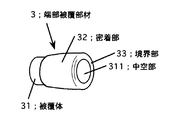
図1は、本発明による端部被覆部材の斜視図、図2はその断面図であるが、これらの図より明らかなように、本発明による端部被覆部材3は、ライン状部材(以下、電線を例に説明する)の端部11を覆うための筒状の被覆体31とこの被覆体31の一方の端部に形成された開口端に接続する密着部32を有している。
【0010】
前記被覆体31は、図1および図2により明らかなように、一方の端部には開口端が形成されており、他方の端部は閉鎖された構造の中空筒状の構造になっている。そして前記被覆体31は、前記電線1より径の大きい中空部311を有しており、一方前記密着部32は前記電線1より径が若干小さな中空部321が形成されている。そして、この被覆体31と密着部32は徐々に縮径する中空部331を備えた境界部33を介して接続した構造になっている。これらの中空部311、321、331は相互に連通しており、前記電線1を被覆体31の中空部311に挿入可能な構造になっている(図3(c)参照)。
【0011】
本発明において、前記密着部32は、ほぼ境界部33を支点として先端より外側に捲れ上がっており、密着部32の内壁が外側を向いた構造になっている。このため、前記端部被覆部材の径は、ほぼ被覆体31の径に相当する径になっており、この径より小さな径である電線1を容易に挿入することが可能である。
【0012】
このような本発明による端部被覆部材を使用するには、まず電線1の端部11を被覆体31の中空部311に挿入する(図3(a)参照)。その後、捲れ上がった密着部32を、図3(b)の矢印方向に力を負荷して徐々に捲れを解消していく。前記密着部32の先端には、被覆体31に当接するような突起34が設けられており、この突起34によって前記密着部32と被覆体31間に、空間Sを形成するようになっている。このように、空間Sを形成することにより、前記密着部32と被覆体31との密着が軽減され、捲れを解消する作業を容易に行うことが可能になる。
【0013】
最後まで捲れを解消したときには、前記密着部32は電線1の径より若干小さいため、電線1に密着することになり、前記端部11は気密に被覆されることになる。
【0014】
このような作用を営むものであるから、本発明による端部被覆部材は、弾性が必要であり、電線の端部被覆部材として使用するときには、絶縁性が良好であることが望まれる。また捲れ上がった状態で運搬、保存されることから、少なくとも半年程度は捲れを解消したときに十分に気密が確保できる程度の永久伸び特性が必要である。この永久伸びは、好ましくは30%以内であるのがよい。上述のように30%を超えると、十分に気密が確保できない恐れがあるからである。また、密着部32を捲れ上げる必要があることから、伸び特性は、好ましくは500%以上であるのがよい。500%未満であると、密着部を捲れ上げるときに、破損を生じる恐れがある。また拡径率(もとの径に対する拡げた時の径)は、400%以内であるのがよい。400%を超えると、永久伸びが落ち、捲れを解消したとき十分気密が確保できない恐れがあるからである。
【0015】
このような端部被覆部材を製造するための材料としては、たとえばエチレン・プロピレンゴム、シリコーンゴムなどを使用することができる。
【0016】
さらに前記被覆部31と密着部32の膜厚の比は、好ましくは1:1〜1/2であるのがよい。密着部32の膜厚が厚くなると、捲れ上げる作業が困難になり、さらに、密着部32が破損する恐れがある。一方、1/2未満であると捲れ上げる作業は簡単になるが、密着部32の電線1に対する気密性が低下するという問題を生じる。
【0017】
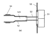
このような端部被覆部材3は、図4に斜視図を、図5(a),(b)に平面図を示すような端部被覆部材の製造治具5を使用して製造する。すなわち、端部被覆部材の製造治具5は前記密着部32の中空部321の拡径方向(たとえば図5(b)に示すように45°方向)に移動可能な拡径ピン52を有している。この実施例においては、この拡径ピン52は複数の基台51(図4では4つ)にそれぞれ立設され、固定されており、前記基台51が前記中空部321の拡径方向に移動することによって、前記拡径ピン52が拡径方向に移動するようになっている。さらに前記拡径状態の拡径ピン52が当接するような内径を有する捲れ上げリング53が備えられており、この捲れ上げリング53によって前記拡径ピン52の拡径が制御されるようになっている。さらにこの捲れ上げリング53は基台51と反対方向(図4において左方向)に平行に移動するようになっている。
【0018】
また、拡径された接続部被覆部材の密着部32を基台51方向に押し込む押し込みリング54を有している。この押し込みリング54の外径は拡径ピン52が拡径したときの内径より小さな径となっているとともに、前記基台51方向に平行に移動可能になっている。さらに前記拡径ピン52の拡径中心と前記捲れ上げリング53および押し込みリング54の径の中心は一致するようになっている。
【0019】
図6、図7、図8に示すように、まず、複数の拡径ピン52の間隔が最小の時に、密着部12が捲れ上がっていない端部被覆部材前駆体(密着部、境界部、被覆体は直線上に接続している)の密着部32の中空部121に前記拡径ピン52を嵌め合わせる(図6参照)。このとき押し込みリング54は前記端部被覆部材前駆体の外側に嵌込まれている。
【0020】
このような状態で、前記基台51を拡径方向に移動させる(図7参照)と、前記密着部12は拡径することになる。このとき前記拡径ピン52は捲れ上げリング53の内径に当接し、拡径が制御される。このような状態で、捲れ上げリング53を基台51と反対方向に、一方押し込みリング54を基台51方向に移動させる。捲れ上げリング53は密着部32の端部を基台51と反対方向に押し、一方押し込みリング54は密着部32の外壁を拡径ピン52の拡径の内側に押し込むことになるため、密着部12は外側方向に捲れ上がることになり(図8参照)、前記捲れ上げリング53を境界部13付近まで移動させることによって、図1に示す本発明の端部被覆部材3が得られる。
【0021】
上記実施例においては、電線を例として説明したが、本発明はこれに限定されるものではなく、他のライン状部材、たとえば光ファイバケーブル、ガス管などの端部を被覆することができるのは明らかである。
【0022】
【発明の効果】
以上説明したように本発明による端部被覆部材によれば、密着部は、好ましくは前記被覆体と密着部の境界部を支点として外側方向に捲れ上がっているため、前記ライン部材の端部を容易に挿入することができ、かつ前記捲れを直すことによって、前記密着部は前記ライン部材と密着することになるため、テープを使用することなく、容易に気密に被覆することが可能になる。
【図面の簡単な説明】
【図1】本発明による端部被覆部材の一実施例の斜視図。
【図2】 本発明による端部被覆部材の一実施例の断面図。
【図3】前記実施例の端部を被覆するときの説明図。
【図4】本発明による端部被覆部材の製造治具の斜視図。
【図5】本発明による端部被覆部材の製造治具の平面図。
【図6】端部被覆部材の製造治具を使用して本発明の端部被覆部材を製造する方法を説明する図。
【図7】端部被覆部材の製造治具を使用して本発明の端部被覆部材を製造する方法を説明する図。
【図8】端部被覆部材の製造治具を使用して本発明の端部被覆部材を製造する方法を説明する図。
【図9】従来のライン状部材の保存状態を示す説明図。
【符号の説明】
3 端部被覆部材
31 被覆体
311 中空部
32 密着部
321 中空部
33 境界部
331 中空部
34 突起
5 端部被覆部材の製造治具。
51 基台
52 拡径ピン
53 捲れ上げリング
54 押し込みリング[0001]
[Industrial application fields]
The present invention is an end covering member, the ends of such hermetically wires in detail in the al, and easily about the coatable edge covering member.
[0002]
[Prior art and problems]
Generally, the line-shaped member such as the
[0003]
However, the operation of winding and covering the end portion of the tape as described above has a drawback that it requires some skill and is troublesome.
[0004]
The present invention has been made in view of the above problems, and an object thereof is to provide a line-shaped member end can be covered easily gastight edge covering member of.
[0005]
[Means for solving problems]
To solve the above problems, edge covering member according to the present invention, a tubular jacket having a hollow portion of larger diameter than the diameter of the end portion to be coated, be connected covered the open end of the jacket A close contact portion having a hollow portion having a diameter smaller than the diameter of the power end portion, and the covering body and the close contact portion are integrally formed of an elastomer material, and the close contact portion is formed at the tip of the cover body. has a projection for forming a space between the contact portion in contact with the an outer wall and said cover member, said contact portion is raised Ri wound outward, the contact portion is rolled up In the state, the opening end of the covering body has an inner diameter larger than the diameter of the end portion to be covered without being expanded by another member or other diameter expanding means .
[0008]
According to the present invention, the close contact portion preferably swells outwardly with the boundary between the covering and the close contact portion as a fulcrum, so that the end of the line-shaped member can be easily inserted, and the By correcting the curling, the end portion can be easily and airtightly covered without using a tape because the line-shaped member comes into close contact.
[0009]
【Example】
FIG. 1 is a perspective view of an end covering member according to the present invention, and FIG. 2 is a sectional view thereof. As is clear from these drawings, the end covering member 3 according to the present invention is a linear member (hereinafter, A cylindrical covering 31 for covering the
[0010]
As apparent from FIGS. 1 and 2, the
[0011]
In the present invention, the
[0012]
In order to use such an end covering member according to the present invention, first, the
[0013]
When the wrinkle is eliminated to the end, the
[0014]
Since such an action is performed, the end covering member according to the present invention needs to be elastic, and when used as an end covering member of an electric wire, it is desirable that the end covering member has good insulation. In addition, since it is transported and stored in a squeezed state, it must have a permanent elongation characteristic that can secure sufficient airtightness when squeezing is eliminated for at least half a year. This permanent elongation is preferably within 30%. This is because if it exceeds 30% as described above, sufficient airtightness may not be ensured. Moreover, since it is necessary to roll up the
[0015]
As a material for manufacturing such an end covering member, for example, ethylene / propylene rubber, silicone rubber, or the like can be used.
[0016]
Furthermore, the film thickness ratio between the
[0017]
Such an end covering member 3 is manufactured using a
[0018]
Moreover, it has the pushing
[0019]
As shown in FIGS. 6, 7, and 8, first, an end covering member precursor (contact portion, boundary portion, covering portion) in which the
[0020]
In such a state, when the
[0021]
In the above embodiment, the electric wire has been described as an example. However, the present invention is not limited to this, and other line-shaped members such as an optical fiber cable and a gas pipe can be covered. Is clear.
[0022]
【The invention's effect】
As described above, according to the end covering member according to the present invention, the close contact portion preferably swells outwardly with the boundary portion between the cover and the close contact portion as a fulcrum, so the end portion of the line member is By being able to insert easily and correcting the curling, the close contact portion comes into close contact with the line member, so that it can be easily and airtightly covered without using a tape.
[Brief description of the drawings]
FIG. 1 is a perspective view of an embodiment of an end covering member according to the present invention.
FIG. 2 is a cross-sectional view of an embodiment of an end covering member according to the present invention.
FIG. 3 is an explanatory diagram when covering an end portion of the embodiment.
FIG. 4 is a perspective view of an end covering member manufacturing jig according to the present invention.
FIG. 5 is a plan view of an end covering member manufacturing jig according to the present invention.
FIG. 6 is a view for explaining a method of manufacturing an end cover member of the present invention using an end cover member manufacturing jig.
FIG. 7 is a view for explaining a method of manufacturing the end cover member of the present invention using an end cover member manufacturing jig.
FIG. 8 is a view for explaining a method of manufacturing the end cover member of the present invention using the end cover member manufacturing jig.
FIG. 9 is an explanatory view showing a storage state of a conventional line-shaped member.
[Explanation of symbols]
3
51
Claims (4)
Priority Applications (1)
| Application Number | Priority Date | Filing Date | Title |
|---|---|---|---|
| JP2000053244A JP4584395B2 (en) | 2000-02-29 | 2000-02-29 | End covering member |
Applications Claiming Priority (1)
| Application Number | Priority Date | Filing Date | Title |
|---|---|---|---|
| JP2000053244A JP4584395B2 (en) | 2000-02-29 | 2000-02-29 | End covering member |
Publications (3)
| Publication Number | Publication Date |
|---|---|
| JP2001241592A JP2001241592A (en) | 2001-09-07 |
| JP2001241592A5 JP2001241592A5 (en) | 2007-02-01 |
| JP4584395B2 true JP4584395B2 (en) | 2010-11-17 |
Family
ID=18574658
Family Applications (1)
| Application Number | Title | Priority Date | Filing Date |
|---|---|---|---|
| JP2000053244A Expired - Fee Related JP4584395B2 (en) | 2000-02-29 | 2000-02-29 | End covering member |
Country Status (1)
| Country | Link |
|---|---|
| JP (1) | JP4584395B2 (en) |
Families Citing this family (2)
| Publication number | Priority date | Publication date | Assignee | Title |
|---|---|---|---|---|
| JP5908519B2 (en) * | 2014-03-27 | 2016-04-26 | 中国電力株式会社 | Insulating cover, conductor end insulating method, and arc horn electrode end insulating method |
| JP6421353B1 (en) * | 2018-02-14 | 2018-11-14 | アマネファクトリー株式会社 | MASSAGE BALL AND MASSAGE BALL MANUFACTURING METHOD |
Citations (7)
| Publication number | Priority date | Publication date | Assignee | Title |
|---|---|---|---|---|
| JPS6031132U (en) * | 1983-08-10 | 1985-03-02 | 株式会社フジクラ | Heat-shrinkable tube for cable connection |
| JPS63199460U (en) * | 1987-06-15 | 1988-12-22 | ||
| JPH06238745A (en) * | 1993-02-17 | 1994-08-30 | Tokico Ltd | Rubber tube bending apparatus and method |
| JPH0735289A (en) * | 1993-07-26 | 1995-02-07 | Inoac Corp | Protector of pipeline joint part and pipeline joint part protecting method |
| JPH081775A (en) * | 1994-06-27 | 1996-01-09 | Sumitomo Electric Ind Ltd | Heat-shrinkable tube and production thereof |
| JPH1169594A (en) * | 1997-08-07 | 1999-03-09 | Hitachi Cable Ltd | Insulated wire room-temperature heat shrinkable cover |
| JPH1198674A (en) * | 1997-09-25 | 1999-04-09 | Minnesota Mining & Mfg Co <3M> | Cap for cable end part covering and treatment method therefor |
-
2000
- 2000-02-29 JP JP2000053244A patent/JP4584395B2/en not_active Expired - Fee Related
Patent Citations (7)
| Publication number | Priority date | Publication date | Assignee | Title |
|---|---|---|---|---|
| JPS6031132U (en) * | 1983-08-10 | 1985-03-02 | 株式会社フジクラ | Heat-shrinkable tube for cable connection |
| JPS63199460U (en) * | 1987-06-15 | 1988-12-22 | ||
| JPH06238745A (en) * | 1993-02-17 | 1994-08-30 | Tokico Ltd | Rubber tube bending apparatus and method |
| JPH0735289A (en) * | 1993-07-26 | 1995-02-07 | Inoac Corp | Protector of pipeline joint part and pipeline joint part protecting method |
| JPH081775A (en) * | 1994-06-27 | 1996-01-09 | Sumitomo Electric Ind Ltd | Heat-shrinkable tube and production thereof |
| JPH1169594A (en) * | 1997-08-07 | 1999-03-09 | Hitachi Cable Ltd | Insulated wire room-temperature heat shrinkable cover |
| JPH1198674A (en) * | 1997-09-25 | 1999-04-09 | Minnesota Mining & Mfg Co <3M> | Cap for cable end part covering and treatment method therefor |
Also Published As
| Publication number | Publication date |
|---|---|
| JP2001241592A (en) | 2001-09-07 |
Similar Documents
| Publication | Publication Date | Title |
|---|---|---|
| AU2002219381B2 (en) | Cable gland assembly | |
| JP4107681B2 (en) | Method and apparatus for positioning by inserting a sheathed elastic cable sleeve into a cable connection | |
| JPH05207632A (en) | Cable reel | |
| JP4584395B2 (en) | End covering member | |
| JP4476418B2 (en) | Connection part covering member | |
| KR102135673B1 (en) | Manufacturing method of drawing shell of socket connector with thin film sealing support wall | |
| JPH09219123A (en) | Grommet | |
| JP3199639B2 (en) | Insulation tube for wire branch connection | |
| KR101411111B1 (en) | Teflon corn for inserting pre-mold insulation unit of pre-mold joint for ultar high voltage power cable | |
| EP0099719B1 (en) | Prefabricated rubber-elastic enclosure for electrical cables | |
| JP3417540B2 (en) | Grommet | |
| JP2001315201A (en) | Pressing tool for assembling ambient temperature shrinkable tube unit | |
| JP4002127B2 (en) | Cable connection processing method | |
| JP4403569B2 (en) | Method of assembling cable connecting portion and cable connecting member | |
| JP2002027627A (en) | Conductor connection tube and power cable joint using the connection tube | |
| JP3231627U (en) | Protective equipment | |
| JPH10512135A (en) | Pre-stretch module barrier boot | |
| JPH0511428Y2 (en) | ||
| JP2018125162A (en) | Sleeve cover | |
| JP3059573U (en) | Nominal line storage case | |
| JP3072236U (en) | Insulating cap made of flexible material | |
| JP2000224727A (en) | Cylindrical protecting appliance | |
| JP2001105491A (en) | Diameter enlarging method for normal temperature shrinking type covering material | |
| JP2000102128A (en) | Cable catcher | |
| JP2021126436A (en) | Plate coil-added tube and manufacturing method therefor |
Legal Events
| Date | Code | Title | Description |
|---|---|---|---|
| A521 | Written amendment |
Free format text: JAPANESE INTERMEDIATE CODE: A523 Effective date: 20061207 |
|
| A621 | Written request for application examination |
Free format text: JAPANESE INTERMEDIATE CODE: A621 Effective date: 20061207 |
|
| RD02 | Notification of acceptance of power of attorney |
Free format text: JAPANESE INTERMEDIATE CODE: A7422 Effective date: 20071218 |
|
| RD04 | Notification of resignation of power of attorney |
Free format text: JAPANESE INTERMEDIATE CODE: A7424 Effective date: 20071218 |
|
| A977 | Report on retrieval |
Free format text: JAPANESE INTERMEDIATE CODE: A971007 Effective date: 20090827 |
|
| A131 | Notification of reasons for refusal |
Free format text: JAPANESE INTERMEDIATE CODE: A131 Effective date: 20090908 |
|
| A521 | Written amendment |
Free format text: JAPANESE INTERMEDIATE CODE: A523 Effective date: 20091106 |
|
| A131 | Notification of reasons for refusal |
Free format text: JAPANESE INTERMEDIATE CODE: A131 Effective date: 20100316 |
|
| TRDD | Decision of grant or rejection written | ||
| A01 | Written decision to grant a patent or to grant a registration (utility model) |
Free format text: JAPANESE INTERMEDIATE CODE: A01 Effective date: 20100831 |
|
| A01 | Written decision to grant a patent or to grant a registration (utility model) |
Free format text: JAPANESE INTERMEDIATE CODE: A01 |
|
| A61 | First payment of annual fees (during grant procedure) |
Free format text: JAPANESE INTERMEDIATE CODE: A61 Effective date: 20100902 |
|
| R150 | Certificate of patent or registration of utility model |
Ref document number: 4584395 Country of ref document: JP Free format text: JAPANESE INTERMEDIATE CODE: R150 Free format text: JAPANESE INTERMEDIATE CODE: R150 |
|
| FPAY | Renewal fee payment (event date is renewal date of database) |
Free format text: PAYMENT UNTIL: 20130910 Year of fee payment: 3 |
|
| S531 | Written request for registration of change of domicile |
Free format text: JAPANESE INTERMEDIATE CODE: R313531 |
|
| R350 | Written notification of registration of transfer |
Free format text: JAPANESE INTERMEDIATE CODE: R350 |
|
| LAPS | Cancellation because of no payment of annual fees |


