JP4581199B2 - Image signal processing apparatus, image signal processing method, learning apparatus, learning method, and recording medium - Google Patents
Image signal processing apparatus, image signal processing method, learning apparatus, learning method, and recording medium Download PDFInfo
- Publication number
- JP4581199B2 JP4581199B2 JP2000251497A JP2000251497A JP4581199B2 JP 4581199 B2 JP4581199 B2 JP 4581199B2 JP 2000251497 A JP2000251497 A JP 2000251497A JP 2000251497 A JP2000251497 A JP 2000251497A JP 4581199 B2 JP4581199 B2 JP 4581199B2
- Authority
- JP
- Japan
- Prior art keywords
- pixel
- image signal
- feature information
- class
- pixels
- Prior art date
- Legal status (The legal status is an assumption and is not a legal conclusion. Google has not performed a legal analysis and makes no representation as to the accuracy of the status listed.)
- Expired - Fee Related
Links
- 238000000034 method Methods 0.000 title claims description 63
- 238000003672 processing method Methods 0.000 title claims description 10
- 238000000605 extraction Methods 0.000 claims description 95
- 230000003044 adaptive effect Effects 0.000 claims description 32
- 239000003086 colorant Substances 0.000 claims description 23
- 238000004364 calculation method Methods 0.000 claims description 12
- 238000003384 imaging method Methods 0.000 claims description 12
- 230000006978 adaptation Effects 0.000 description 32
- 238000006243 chemical reaction Methods 0.000 description 20
- 238000010586 diagram Methods 0.000 description 19
- 239000000284 extract Substances 0.000 description 9
- 230000007547 defect Effects 0.000 description 7
- 239000011159 matrix material Substances 0.000 description 6
- 238000003708 edge detection Methods 0.000 description 5
- 230000000295 complement effect Effects 0.000 description 4
- 238000001514 detection method Methods 0.000 description 3
- 230000003287 optical effect Effects 0.000 description 3
- 238000003491 array Methods 0.000 description 2
- 238000000354 decomposition reaction Methods 0.000 description 2
- 230000002950 deficient Effects 0.000 description 2
- 230000000694 effects Effects 0.000 description 2
- JMANVNJQNLATNU-UHFFFAOYSA-N oxalonitrile Chemical compound N#CC#N JMANVNJQNLATNU-UHFFFAOYSA-N 0.000 description 2
- 238000004088 simulation Methods 0.000 description 2
- 230000005540 biological transmission Effects 0.000 description 1
- 238000004422 calculation algorithm Methods 0.000 description 1
- 238000001444 catalytic combustion detection Methods 0.000 description 1
- 238000004590 computer program Methods 0.000 description 1
- 238000001914 filtration Methods 0.000 description 1
- 230000006870 function Effects 0.000 description 1
- 238000005070 sampling Methods 0.000 description 1
Images


Landscapes
- Facsimile Image Signal Circuits (AREA)
- Color Image Communication Systems (AREA)
- Image Processing (AREA)
- Color Television Image Signal Generators (AREA)
- Processing Of Color Television Signals (AREA)
Description
【0001】
【発明の属する技術分野】
本発明は画像信号処理装置、画像信号処理方法、学習装置、学習方法及び記録媒体に関し、特に、1つの固体イメージセンサにより得られる画像に対し、その画像信号の1画素が赤(R:Red) 成分、緑(G:Green) 成分及び青(B:Blue)成分をもつように、クラス分類適応処理を用いて色成分を補間する画像信号処理装置、画像信号処理方法、学習装置、学習方法及び記録媒体に関する。
【0002】
【従来の技術】
CCD(Charge Coupled Device) イメージセンサなどの固体イメージセンサを用いた撮像装置には、主に、1つのCCDイメージセンサを用いた単板方式のもの(以後、単板式カメラという)と、3つのCCDイメージセンサを用いた3板方式のもの(以後、3板式カメラという)とがある。
【0003】
3板式カメラでは、例えばR信号用、G信号用及びB信号用の3つのCCDイメージセンサを用いて、その3つのCCDイメージセンサにより3原色信号を得る。そして、この3原色信号から生成されるカラー画像信号が記録媒体に記録される。
【0004】
単板式カメラでは、1画素毎に割り当てられた色フィルタアレイからなる色コーディングフィルタが前面に設置された1つのCCDイメージセンサを用いて、上記色コーディングフィルタにより色コーディングされた色成分の信号を1画素毎に得る。上記色コーディングフィルタを構成する色フィルタアレイとしては、例えば、R(Red) ,G(Green) ,B(Blue) の原色フィルタアレイや、Ye(Yellow) ,Cy(Cyanogen),Mg(Magenta) の補色フィルタアレイが用いられている。そして、単板式カメラにおいては、CCDイメージセンサにより1画素毎に1つの色成分の信号を得て、各画素が持っている色成分の信号以外の色信号を線形補間処理により生成して、3板式カメラにより得られる画像に近い画像を得るようにしていた。ビデオカメラなどにおいて、小型化、軽量化を図る場合に、単板式が採用されている。
【0005】
単板式カメラにおいて、例えば図22の(A)に示すような色配列の色フィルタアレイにより構成された色コーディングフィルタが設けられたCCDイメージセンサは、R,G,Bの3原色のうちの1つの色のフィルタが配置された各画素から、そのフィルタの色に対応する画像信号のみが出力される。すなわち、Rの色フィルタが配置された画素からは、R成分の画像信号は出力されるが、G成分及びB成分の画像信号は出力されない。同様に、Gの画素からは、G成分の画像信号のみが出力され、R成分及びB成分の画像信号は出力されず、Bの画素からは、B成分の画像信号のみが出力され、R成分及びG成分の画像信号は出力されない。
【0006】
ここで、図22の(A)に示す色フィルタアレイの色配列は、ベイヤー配列と称される。この場合においては、Gの色フィルタが市松状に配され、残った部分にRとBが一列毎に交互に配されている。
【0007】
しかしながら、後段において各画素の信号を処理する際、各画素毎にR成分,G成分及びB成分の画像信号が必要となる。そこで、従来、n×m(n及びmは正の整数)個の画素で構成されるCCDイメージセンサの出力から、図22の(B)に示すように、n×m個のR画素の画像信号、n×m個のG画素の画像信号及びn×m個のB画素の画像信号、すなわち、3板式カメラのCCD出力相当の画像信号が、それぞれ補間演算により求められ、それらの画像信号が後段に出力される。
【0008】
そして、さらに、例えば4倍密度の画像信号を生成する場合、図22の(C)に示すように、n×m個のR画素の画像信号から2n×2m個のR画素の画像信号が補間演算により求められ、n×m個のG画素の画像信号から2n×2m個のG画素の画像信号が補間演算により求められ、さらに、n×m個のB画素の画像信号から、2n×2m個のB画素の画像信号が補間演算により求められる。
【0009】
【発明が解決しようとする課題】
CCDイメージセンサにより1画素毎に1つの色成分の信号を得て、各画素が持っている色成分の信号以外の色信号を線形補間処理により生成する単板式カメラにおいては、画像の斜め線や細線の部分で上記線形補間処理に破綻を生じ易いという問題点がある。
【0010】
また、線形処理を行うことにより色信号の補間を行っているので、画像の波形が鈍つてしまい、画像全体が不鮮明となってしまうので、輪郭強調処理等の処理を行って、見掛けの解像度を上げる処理が必要であった。
【0011】
さらに、線形補間と異なる処理方法として、単板式カメラのCCD出力から、R,G,Bの3原色の各画像信号毎に独立にクラス分類適応処理を行うことよって3板式カメラのCCD出力に相当する画像信号を生成することが提案されている(国際公開番号:WO96/07275)。しかしながら、クラス分類適応処理においても、基本的に波形によるクラス分類を行っているため、画像の斜め線や細線の部分で波形の連続性が壊れる等の破綻を生じる傾向にあった。これは、ベイヤ配列等の色フィルタの配列に起因する問題であって、通常の波形によるクラス分類では対応できないのが現状であった。
【0012】
本発明は、このような状況に鑑みてなされたものであり、画像の斜め線や細線の部分に対応したクラス分類適応処理により、解像度が高く、細部まで鮮明な画像を再現できる画像信号を単板式カメラのCCD出力から得られるようにすることを目的とする。
【0013】
【課題を解決するための手段】
本発明は、画素位置毎に輝度あるいは複数の色のうちのいずれか1つを表す色成分を画素データとして持つ入力画像信号を処理する画像信号処理装置において、上記入力画像信号を取得する固体撮像素子と、上記固体撮像素子で取得した入力画像信号の注目画素毎に、上記注目画素近傍の複数の画素を第1の画素として抽出する第1の抽出手段と、上記第1の抽出手段で抽出された複数の画素の各画素データに基づいて第1の特徴情報を生成する第1の特徴情報生成手段と、上記入力画像信号の注目画素毎に、上記注目画素近傍の複数の画素を第2の画素として抽出する第2の抽出手段と、上記第2の画素の各画素データに基づいて、上記注目画素近傍の斜め線の画素及び細線の画素の有無を判定し、該斜め線の画素及び該細線の画素の少なくとも一方が存在する場合には、該画素の種類を第2の特徴情報として生成する第2の特徴情報生成手段と、上記第1の特徴情報及び第2の特徴情報に基づいて1つのクラスを決定するクラス決定手段と、各クラス毎の予測係数セットが記憶された記憶手段と、該記憶手段に記憶されている上記クラス決定手段で決定されたクラスに応じた予測係数セットと、画素抽出手段によって抽出された上記注目画素近傍の複数の画素値とを乗算した線形和から、上記注目画素の色成分とは異なる色成分を持つ画素を生成する演算手段とを有する画素生成手段とを備える。
【0014】
また、本発明は、画素位置毎に輝度あるいは複数の色のうちのいずれか1つを表す色成分を画素データとして持つ入力画像信号を処理する画像信号処理方法において、上記入力画像信号を取得する取得ステップと、上記取得ステップで取得した入力画像信号の注目画素毎に、上記注目画素近傍の複数の画素を第1の画素として抽出する第1の抽出ステップと、上記第1の抽出ステップで抽出された複数の画素の各画素データに基づいて第1の特徴情報を生成する第1の特徴情報生成ステップと、上記取得ステップで取得した入力画像信号の注目画素毎に、上記注目画素近傍の複数の画素を第2の画素として抽出する第2の抽出ステップと、上記第2の画素の各画素データに基づいて、上記注目画素近傍の斜め線の画素及び細線の画素の有無を判定し、該斜め線の画素及び該細線の画素の少なくとも一方が存在する場合には、該画素の種類を第2の特徴情報として生成する第2の特徴情報生成ステップと、上記第1の特徴情報及び第2の特徴情報に基づいて1つのクラスを決定するクラス決定ステップと、各クラス毎の予測係数セットが記憶された記憶手段に記憶されている上記クラス決定ステップで決定されたクラスに応じた予測係数セットと、画素抽出手段によって抽出された上記注目画素近傍の複数の画素値との演算を行うことにより、上記注目画素の色成分とは異なる色成分を持つ画素を生成する画素生成ステップとを備える。
【0015】
また、本発明は、画素位置毎に輝度あるいは複数の色のうちのいずれか1つを表す色成分を画素データとして持つ入力画像信号を処理する画像信号処理を行うコンピュータ制御可能なプログラムが記録された記録媒体において、上記プログラムは、上記入力画像信号を取得する取得ステップと、上記取得ステップで取得した入力画像信号の注目画素毎に、上記注目画素近傍の複数の画素を第1の画素として抽出する第1の抽出ステップと、上記第1の抽出ステップで抽出された複数の画素の各画素データに基づいて第1の特徴情報を生成する第1の特徴情報生成ステップと、上記取得ステップで取得した入力画像信号の注目画素毎に、上記注目画素近傍の複数の画素を第2の画素として抽出する第2の抽出ステップと、上記第2の画素の各画素データに基づいて、上記注目画素近傍の斜め線の画素及び細線の画素の有無を判定し、該斜め線の画素及び該細線の画素の少なくとも一方が存在する場合には、該画素の種類を第2の特徴情報として生成する第2の特徴情報生成ステップと、上記第1の特徴情報及び第2の特徴情報に基づいて1つのクラスを決定するクラス決定ステップと、各クラス毎の予測係数セットが記憶された記憶手段に記憶されている上記クラス決定ステップで決定されたクラスに応じた予測係数セットと、画素抽出手段によって抽出された上記注目画素近傍の複数の画素値との演算を行うことにより、上記注目画素の色成分とは異なる色成分を持つ画素を生成する画素生成ステップとを備える。
【0016】
また、本発明に係る学習装置は、画素位置毎に輝度あるいは複数の色のうちのいずれか1つの色成分を画像データとして持つ生徒画像信号の注目画素の近傍の複数の画素を第1の画素として抽出する第1の抽出手段と、上記第1の抽出手段で抽出された複数の画素の各画素データに基づいて第1の特徴情報を生成する第1の特徴情報生成手段と、上記生徒画像信号の注目画素毎に、上記注目画素近傍の複数の画素を第2の画素として抽出する第2の抽出手段と、上記第2の画素の各画素データに基づいて、上記注目画素近傍斜め線の画素及び細線の画素の有無を判定し、該斜め線の画素及び該細線の画素の少なくとも一方が存在する場合には、該画素の種類を第2の特徴情報として生成する第2の特徴情報生成手段と、上記第1の特徴情報及び第2の特徴情報に基づいて1つのクラスを決定するクラス決定手段と、上記生徒画像信号と対応する画像信号であり、画素位置毎に輝度あるいは複数の色のうちのいずれか1つの色成分を画像データとして持つ教師画像信号から、上記生徒画像信号の注目画素の位置に相当する位置の近傍の複数の画素を第3の画素として抽出する第3の抽出手段と、上記第1及び第3の抽出手段で抽出された複数の画素の各画素データに基づいて、上記クラス毎に、上記生徒画像信号に相当する画像信号から上記教師画像信号に相当する画像信号を生成するための予測演算に用いる予測係数セットを生成する予測係数生成手段とを備える。
【0017】
また、本発明に係る学習方法は、画素位置毎に輝度あるいは複数の色のうちのいずれか1つの色成分を画像データとして持つ生徒画像信号の注目画素の近傍の複数の画素を第1の画素として抽出する第1の抽出ステップと、上記第1の抽出ステップで抽出された複数の画素の各画素データに基づいて第1の特徴情報を生成する第1の特徴情報生成ステップと、上記生徒画像信号の注目画素毎に、上記注目画素近傍の複数の画素を第2の画素として抽出する第2の抽出ステップと、上記第2の画素の各画素データに基づいて、上記注目画素近傍の斜め線の画素及び細線の画素の有無を判定し、該斜め線の画素及び該細線の画素の少なくとも一方が存在する場合には、該画素の種類を第2の特徴情報として生成する第2の特徴情報生成ステップと、上記第1の特徴情報及び第2の特徴情報に基づいて1つのクラスを決定するクラス決定ステップと、上記生徒画像信号と対応する画像信号であり、画素位置毎に輝度あるいは複数の色のうちのいずれか1つの色成分を画像データとして持つ教師画像信号から、上記生徒画像信号の注目画素の位置に相当する位置の近傍の複数の画素を第3の画素として抽出する第3の抽出ステップと、上記第1及び第3の抽出ステップで抽出された複数の画素の各画素データに基づいて、上記クラス毎に、上記生徒画像信号に相当する画像信号から上記教師画像信号に相当する画像信号を生成するための予測演算に用いる予測係数セットを生成する予測係数生成ステップとを備える。
【0018】
さらに、本発明は、クラスに応じた予測係数セットを生成するための学習処理を行うコンピュータ制御可能なプログラムが記録された記録媒体において、上記プログラムは、画素位置毎に輝度あるいは複数の色のうちのいずれか1つの色成分を画像データとして持つ生徒画像信号の注目画素の近傍の複数の画素を第1の画素として抽出する第1の抽出ステップと、上記第1の抽出ステップで抽出された複数の画素の各画素データに基づいて第1の特徴情報を生成する第1の特徴情報生成ステップと、上記生徒画像信号の注目画素毎に、上記注目画素近傍の複数の画素を第2の画素として抽出する第2の抽出ステップと、上記第2の画素の各画素データに基づいて、上記注目画素近傍の斜め線の画素及び細線の画素の有無を判定し、該斜め線の画素及び該細線の画素の少なくとも一方が存在する場合には、該画素の種類を第2の特徴情報として生成する第2の特徴情報生成ステップと、上記第1の特徴情報及び第2の特徴情報に基づいて1つのクラスを決定するクラス決定ステップと、上記生徒画像信号と対応する画像信号であり、画素位置毎に輝度あるいは複数の色のうちのいずれか1つの色成分を画像データとして持つ教師画像信号から、上記生徒画像信号の注目画素の位置に相当する位置の近傍の複数の画素を第3の画素として抽出する第3の抽出ステップと、上記第1及び第3の抽出ステップで抽出された複数の画素の各画素データに基づいて、上記クラス毎に、上記生徒画像信号に相当する画像信号から上記教師画像信号に相当する画像信号を生成するための予測演算に用いる予測係数セットを生成する予測係数生成ステップとを備える。
【0019】
【発明の実施の形態】
以下、本発明の実施の形態について、図面を参照して詳細に説明する。
【0020】
本発明は、例えば図1に示すような構成のデジタルスチルカメラ1に適用される。このデジタルスチルカメラ1は、1画素毎に割り当てられたベイヤ配列などの色フィルタからなる色コーディングフィルタ4が前面に設置された1つのCCDイメージセンサ5を用いてカラー撮像を行う単板式カメラであって、被写体からの入射光が、レンズ2により集光され、アイリス3及び色コーディングフィルタ4を介してCCDイメージセンサ5に入射されるようになっている。上記CCDイメージセンサ5の撮像面上には、上記アイリス3により所定レベルの光量とされた入射光により被写体像が結像される。なお、このデジタルスチルカメラ1においては、色コーディングフィルタ4とCCDイメージセンサ5は別体としたが、一体化した構造とすることができる。
【0021】
上記CCDイメージセンサ5は、タイミングジェネレータ9からのタイミング信号により制御される電子シャッタに応じて所定時間にわたって露光を行い、色コーディングフィルタ4を透過した入射光の光量に応じた信号電荷(アナログ量)を画素毎に発生することにより、上記入射光により結像された被写体像を撮像して、その撮像出力として得られる画像信号を信号調整部6に供給する。
【0022】
信号調整部6は、画像信号の信号レベルが一定となるようにゲインを調整するAGC(Automatic Gain Contorol) 回路と、CCDイメージセンサ5が発生する1/fのノイズを除去するCDS(Correiated Double Sampling)回路からなる。
【0023】
上記信号調整部6から出力される画像信号は、A/D変換部7によりアナログ信号からデジタル信号に変換されて、画像信号処理部8に供給される。上記A/D変換部7では、タイミングジェネレータ9からのタイミング信号に応じて、例えば1サンプル10ビットのディジタル撮像信号を生成する。
【0024】
このデジタルスチルカメラ1において、タイミングジェネレータ9は、CCDイメージセンサ5、信号調整部6、A/D変換部7及びCPU(Central Processing Unit) 10に各種タイミング信号を供給する。CPU10は、モータ11を駆動することにより、アイリス3を制御する。また、CPU10は、モータ12を駆動することにより、レンズ2などを移動させ、ズームやオートフォーカスなどの制御をする。さらに、CPU10は、必要に応じ、フラッシュ13により閃光を発する制御を行うようにされている。
【0025】
画像信号処理部8は、A/D変換部7から供給された画像信号に対し、欠陥補正処理、ディジタルクランプ処理、ホワイトバランス調整処理、ガンマ補正処理、クラス分類適応処理を用いた予測処理等の処理を行う。
【0026】
この画像信号処理部8に接続されたメモリ15は、例えば、RAM(Random Access Memory)で構成され、画像信号処理部8が画像処理を行う際に必要な信号を記憶する。画像信号処理部8により処理された画像信号は、インタフェース14を介してメモリ16に記憶される。このメモリ16に記憶された画像信号は、インタフェース14を介してデジタルスチルカメラ1に対して着脱可能な記録媒体17に記録される。
【0027】
なお、モータ11は、CPU10からの制御情報に基づいてアイリス3を駆動し、レンズ2を介して入射される光の量を制御する。また、モータ12は、CPU10からの制御情報に基づいてレンズ2のCCDイメージセンサ2に対するフォーカス状態を制御する。これにより、自動絞り制御動作や自動焦点制御動作が実現される。また、フラッシュ13は、CPU10による制御の下で、被写体に対して所定の閃光を照射する。
【0028】
また、インターフェース14は、画像信号処理部8からの画像信号を必要に応じてメモリ16に記憶し、所定のインターフェース処理を実行した後、記録媒体17に供給し、記憶させる。記録媒体17としては、デジタルスチルカメラ1の本体に対して着脱可能な記録媒体、例えばフロッピーディスク、ハードディスク等のディスク記録媒体、メモリカード等のフラッシュメモリ等を用いることができる。
【0029】
コントローラ18は、CPU10の制御の下で、画像信号処理部8及びインターフェース14に制御情報を供給してそれぞれを制御する。CPU10には、シャッタボタンやズームボタンなどの操作ボタンから構成される操作部20からユーザによる操作情報が入力される。CPU10は、入力された操作情報を基に、上述した各部を制御する。電源部19は、バッテリ19AとDC/DCコンバータ19Bなどを有する。DC/DCコンバータ19Bは、バッテリ19Aからの電力を所定の値の直流電圧に変換し、装置内の各構成要素に供給する。充電可能なバッテリ19Aは、デジタルスチルカメラ1の本体に着脱可能とされている。
【0030】
次に、図2のフローチャートを参照し、図1に示したデジタルスチルカメラ1の動作について説明する。このデジタルスチルカメラ1は、ステップS1において、電源がオンされることにより、被写体の撮像を開始する。すなわち、CPU10は、モータ11及びモータ12を駆動し、焦点を合わせたりアイリス3を調整することにより、レンズ2を介してCCDイメージセンサ5上に被写体像を結像させる。
【0031】
ステップS2では、結像された像をCCDイメージセンサ5により撮像した画像信号が、信号調整部6において、信号レベルが一定となるようにゲイン調整され、さらにノイズが除去され、さらに、A/D変換部7によりデジタル化される。
【0032】
また、ステップS3では、上記A/D変換部7によりデジタル化された画像信号に対して、画像信号処理部8によりクラス分類適応処理を含む画像信号処理を行う。
【0033】
ここで、被写体像は、CCDイメージセンサ5の撮像出力として得られる画像信号を電子ビューファインダに表示するよりユーザが確認できるようになっている。なお、被写体像は、光学的ビューファインダによりユーザが確認できるようにすることもできる。
【0034】
そして、ユーザは、ビューファインダにより確認した被写体像の画像を記録媒体17に記録したい場合、操作部20のシャッタボタンを操作する。デジタルスチルカメラ1のCPU10は、ステップS4において、シャッタボタンが操作されたか否かを判断する。デジタルスチルカメラ1は、シャッタボタンが操作されたと判断するまで、ステップS2〜S3の処理を繰り返し、シャッタボタンが操作されたと判断すると、ステップS5に進む。
【0035】
そして、ステップS5では、画像信号処理部8による画像信号処理が施された画像信号をインターフェース14を介して記録媒体17に記録する。
【0036】
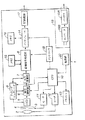
次に、図3を参照して画像信号処理部8について説明する。
【0037】
この画像信号処理部8は、上記A/D変換部7によりデジタル化された画像信号が供給される欠陥補正部21を備える。CCDイメージセンサ5の画素の中で、何らかの原因により入射光に反応しない画素や、入射光に依存せず、電荷が常に蓄えられている画素、換言すれば、欠陥がある画素を検出し、その検出結果に従って、それらの欠陥画素の影響が露呈しないように、画像信号を補正する処理を行う。
【0038】
A/D変換部7では、負の値がカットされるのを防ぐため、一般に信号値を若干正の方向ヘシフトさせた状態でA/D変換が行われている。クランプ部22は、欠陥補正部21により欠陥補正された画像信号に対し、上述したシフト量がなくなるようにクランプする。
【0039】
クランプ部22によりクランプされた画像信号は、ホワイトバランス調整部23に供給される。ホワイトバランス調整部23は、クランプ部22から供給された画像信号のゲインを補正することにより、ホワイトバランスを調整する。このホワイトバランス調整部23によりホワイトバランスが調整された画像信号は、クラス分類適応処理24に供給される。
【0040】
クラス分類適応処理24では、ホワイトバランス調整部23によりホワイトバランスが調整された画像信号について、ADRC(Adaptive Dynamic Range Coding) 処理などにより局所的な画像の特徴量を抽出し、各特徴に基づいてクラスを作成して、クラス毎の処理を行う。具体的な処理としては、単板画像から3板相当画像の変換、任意の画素数への変換、又はそれらの処理を同時に行うなどの各種処理が可能である。ここでは、斜め線や細線に対して特別なクラスを用意することにより、斜め線や細線部分における処理の破綻に対処する。このクラス分類適応処理24によりクラス分類適応処理された画像信号は、ガンマ補正部25に供給される。
【0041】
ガンマ補正部25は、クラス分類適応処理された画像信号の信号レベルをガンマ曲線に従って補正する。このガンマ補正部25によりガンマ補正された画像信号は、補正部26に供給される。
【0042】
補正部26は、上記ガンマ補正部25によりガンマ補正された画像信号に対してエッジ強調等の画像を視覚的に良く見せるために必要ないわゆる画作りのための処理を行う。
【0043】
そして、色空間変換部27は、補正部26によりエッジ強調などの処理が施された画像信号(RGB信号)をマトリクス変換してYUV(輝度Yと色差U,Vとでなる信号)などの所定の信号フォーマットの画像信号に変換する。ただし、マトリクス変換処理を行わず、色空間変換部27からRGB信号をそのまま出力させても良い。この発明の一実施形態では、例えばユーザの操作によって、YUV信号、RGB信号の何れを出力するかを切り換えることが可能とされている。
色空間変換部27により変換された画像信号は、上述のインタフェース14に供給される。
【0044】
ここで、上記図2に示したフローチャートのステップS3において、画像信号処理部8により行われる画像信号処理について、図4のフローチャートを参照して説明する。
【0045】
すなわち、画像信号処理部8では、A/D変換部7によりデジタル化された画像信号に対する画像信号処理を開始すると、先ず、ステップS11において、CCDイメージセンサ5の欠陥の影響が出ないように、欠陥補正部21により画像信号の欠陥補正を行う。そして、次のステップS12では、欠陥補正部21により欠陥補正された画像信号に対して、正の方向にシフトされていた量をもとに戻すクランプ処理をクランプ部22により行う。
【0046】
次のステップS13では、クランプ部22によりクランプされた画像信号に対して、ホワイトバランス調整部23によりホワイトバランスの調整を行い各色信号間のゲインを調整する。さらに、ステップS14では、ホワイトバランスが調整された画像信号に対して、クラス分類適応処理部24により単板画像から3板相当画像の変換を含むクラス分類適応処理を行う。
【0047】
ステップS15では、クラス分類適応処理されたステップS15によって得られた3板式カメラのCCD出力相当の画像信号に対して、ガンマ補正部25によりガンマ曲線に従った補正を施す。
【0048】
ステップS16では、ステップS15でガンマ補正された画像信号に対して、視覚的に良く見せるための補正処理(いわゆる画作り)を行う。ステップS17では、ステップS16によって得られた画像に例えばRGB信号をYUV信号に変換するなどの色空間の変換処理を施す。これにより、例えば記録信号として好適な信号フォーマットを有する出力画像が生成される。
【0049】
この画像信号処理部8におけるクラス分類適応処理部24は、図5に示すように斜め線・細線抽出回路31、クラスタップ抽出回路32、ADRC処理回路33、クラス分類回路34、係数メモリ35、予測タップ抽出回路36及び適応処理回路37からなる。
【0050】
斜め線・細線抽出回路31は、入力画像信号の急峻なエッジ部分の画素の信号値を第2の特徴情報として抽出する第2の抽出手段として機能するものであって、注目領域に対してフィルタ等を用いて斜め線や細線等の補間処理の難しい波形の有無を判定し、そのような波形が存在する場合は、その種類を第2の特徴情報としてクラス分類回路34に渡す。
【0051】
クラスタップ抽出回路32は、注目領域から指定されたタップ位置の画素値を抽出してADRC処理回路33に渡す。ADRC処理回路33は、クラスタップ抽出回路32から渡されたクラスタップの画素値に対してADRC処理を行い、各画素に数ビットの符号を与えたADRC処理の結果を第1の特徴情報としてクラス分類回路34に渡す。
【0052】
クラス分類回路34は、ADRC処理回路33から受け取ったクラスタップのADRC処理結果すなわち第1の特徴情報と、斜め線・細線抽出回路31から受け取った斜め線や細線等の急峻なエッジ部分の画素を示す第2の特徴情報からクラスを決定してクラス番号を係数メモリ35に出力する。係数メモリ35は、クラス分類回路34から受け取ったクラス番号に対応した予測係数セットを読み出して適応処理回路37に渡す。また、予測タップ抽出回路36は、注目領域から指定されたタップ位置の画素値を抽出して適応処理回路37に渡す。
【0053】
そして、適応処理回路37は、予測タップ抽出回路36から渡された予測タップの画素値に、係数メモリ35から読み出されるクラス番号に対応した予測係数セットを乗算し、線形和をもって予測画素値として出力する。
【0054】
すなわち、クラス分類適応処理部24では、図6のフローチャートに示す手順に従ってクラス分類適応処理を行う。
【0055】
ステップS21では、ホワイトバランス調整部23によりホワイトバランスが調整された画像信号について、クラスタップ抽出回路32及び予測タップ抽出回路36によりクラスタップ及び予測タップの画素値を抽出するブロック化処理を行う。
【0056】
次のステップS22では、斜め線・細線抽出回路31により、注目画素に対して、フィルタなどの処理により斜め線や細線が存在するか否かを判定し、その結果を第2の特徴情報としてクラス分類回路34に渡して、クラス分類に反映させる。
【0057】
次のステップS23では、クラスタップ抽出回路32から渡されたクラスタップの画素値に対してADRC処理を行い、各タップに数ビットの符号を与える。
【0058】
次のステップS24では、クラス分類回路34により、ADRC処理回路33によるADRC処理結果すなわち第1の特徴情報と、斜め線・細線抽出回路31によるからの第2の特徴情報からクラスを決定してクラス番号を出力する。
【0059】
次のステップS25では、予測タップ抽出回路36により抽出された予測タップの画素値に、適応処理回路37によりクラス番号に対応した予測係数セットを乗算し、それらの線形和を予測画素値とする。
【0060】
次のステップS26では、全てのブロックについての処理が終了したか否かを判定し、まだ処理していないブロックが存在する場合には、ステップS21に戻り、それ以降の処理を繰り返し実行する。そして、ステップS26において、全てのブロックについての処理が終了したと判定された場合には、クラス分類適応処理を終了して、上述のステップS16に移行する。
【0061】
ここで、上記クラス分類適応処理に用いる予測係数セットは、予め学習により得られるもので、上記係数メモリ35に記憶されている。
【0062】
次に、この学習について説明する。図7は、予測係数セットを学習により得る学習装置40の構成を示すブロック図である。
【0063】
この学習装置40では、クラス分類適応処理の結果として生成されるべき出力画像信号、すなわち3板式カメラのCCD出力相当の画像信号と同一の信号形式を有する高解像度の教師画像信号が間引き回路41及び予測対象画素抽出回路47に供給される。間引き回路41は、教師画像信号から、色フィルタアレイの各色の配置に従つて画素を間引く。間引き処理は、CCDイメージセンサ5に対して着される光学ローパスフィルタを想定したフィルタをかけることによって行う。すなわち、実際の光学系を想定した間引き処理を行う。間引き回路41の出力が生徒画像信号として、斜め線・細線抽出回路42、クラスタップ抽出回路43及び予測タップ抽出回路46に供給される。なお、教師画像信号と生徒画像信号を個別に準備しておくことにより、上記間引き回路41を省略することもできる。
【0064】
斜め線・細線抽出回路42は、生徒画像信号について局所的な注目領域に対してフィルタ等を用いて斜め線や細線等の有無を判定し、その判別結果を第2の特徴情報としてクラス分類回路45に渡す。
【0065】
クラスタップ抽出回路43は、間引き回路41により生成された生徒画像信号から、クラス分類に用いるクラスタップを抽出してADRC処理回路44に渡す。
【0066】
ADRC処理回路44は、クラスタップ抽出回路43から渡されたクラスタップの画素値に対してADRC処理を行い、タップ位置の波形の起伏をクラスに反映させるADRC処理結果を第1の特徴情報としてクラス分類回路45に渡す。
【0067】
クラス分類回路45は、ADRC処理回路44から受け取ったクラスタップのADRC処理結果すなわち第1の特徴情報と、斜め線・細線抽出回路42から受け取った斜め線や細線等の急峻なエッジ部分の画素を示す第2の特徴情報からクラスを決定してクラス番号を第1の演算回路48に出力する。
【0068】
予測タップ抽出回路46は、生徒画像におけるクラスタップとの対応をとりながら、間引き回路41により生成された生徒画像信号から予測タップを抽出して第1の演算回路48に出力する。ここでは、全色信号から予測タップを抽出するものとする。
【0069】
予測対象画素抽出回路47は、生徒画像から抽出されるクラスタップ及び予測タップとの対応をとりながら、予測の対象となる画素値を教師画像信号から抽出して第1の演算回路48に出力する。
【0070】
第1の演算回路48は、クラス分類回路45から出力されたクラス番号毎に、予測タップの画素値と予測対象画素の画素値を、最小自乗法を解くための正規方程式に足し込み、予測係数セットを解とする方程式である正規方程式のマトリクスの係数を演算する。上記第1の演算回路48によって生成される正規方程式のマトリクスの係数が学習データメモリ49に逐次読み込まれ、蓄積される。
【0071】
第2の演算回路50は、学習データメモリ49に蓄積された正規方程式のマトリクスの係数を用いて、コレスキー分解など手法により正規方程式を解く処理を実行する。これにより、クラス毎の予測係数セットが算出される。算出された予測係数セットは、クラスに対応させて係数メモリ51に記憶される。係数メモリ51の記憶内容は、上述の係数メモリ35にロードされ、クラス分類適応処理を行う際に使用される。
【0072】
次に、図8のフローチャートを参照して、学習装置40の動作について説明する。
【0073】
この学習装置40に入力されるデジタル画像信号は、3板式カメラで撮像された画像に相当する画質が得られる画像信号である。なお、3板式カメラで得られる画像信号(教師画像信号)は、1画素の画像信号としてR,G,Bの3原色信号を含んでいるのに対し、単板式カメラで得られる画像信号(生徒画像信号)は、1画素の画像信号としてR,G,Bの3原色信号の内の1つの色信号のみを含んでいる。例えば図9の(A)に示すように3板式カメラで撮像されたHD画像信号をフィルタリングして図9の(B)に示すように1/4サイズのSD画像信号に変換した教師画像信号が、この学習装置40に入力される。
【0074】
ステップS31では、3板式カメラで撮像された画像に相当する画質が得られる教師画像信号に対して間引き回路41により単板カメラのCCDイメージセンサ5に用いられる色コーディングフィルタ4に相当するフィルタをかける間引き処理を実行することで、図9の(C)に示すように単板式カメラのCCDイメージセンサ5が出力する画像信号に対応する生徒画像信号を教師画像信号から生成し、生成した生徒画像信号をクラスタップ抽出回路43及び予測タップ抽出回路46に供給する。
【0075】
ステップS32では、間引き回路41により生成された生徒画像信号から、クラスタップ抽出回路43及び予測タップ抽出回路46によりクラスタップ及び予測タップの画素値を抽出するブロック化処理を行う。また、予測対象画素抽出回路47により、生徒画像から抽出されるクラスタップ及び予測タップとの対応をとりながら、予測対象画素の画素値を教師画像信号から抽出する。
【0076】
ステップS33では、斜め線・細線抽出回路42において生徒画像信号について局所的な注目領域に対してフィルタをかけることにより斜め線や細線等の有無を判定し、その判別結果を第2の特徴情報としてクラス分類回路45に渡す。
【0077】
ステップS34では、ADRC処理回路44により、クラスタップ抽出回路43から渡されたクラスタップの画素値についてADRC処理を行う。
【0078】
ステップS35では、ADRC処理回路44によるクラスタップのADRC処理の結果から、クラス分類回路45によりクラスを決定してクラス番号を出力する。
【0079】
ステップS36では、第1の演算回路48により、クラス分類回路45から出力されたクラス番号にしたがって予測タップの画素値と予測対象画素の画素値を正規方程式に足し込む。
【0080】
ステップS37では、第1の演算回路48による正規方程式への足し込みの処理が、学習の対象画素の全てに対して行われたか否かを判定する。まだ処理していない対象画素が存在する場合には、ステップS32に戻り、また、全て対象画素についての処理が行われていればステップS38に進む。
【0081】
ステップS38では、第2の演算回路50は、学習データメモリ49に蓄積された正規方程式のマトリクスの係数を用いて、コレスキー分解などの手法により正規方程式を解く処理を実行する。
【0082】
ステップS39では、第2の演算回路50による正規方程式を解く処理が、全てのクラス番号の正規方程式について行われたか否かを判定する。まだ処理していない正規方程式が存在する場合には、ステップS38に戻り、また、全ての処理が行われていれば、学習処理を終了する。
【0083】
このようにしてクラスコードと関連付けられて係数メモリ51に記憶された予測係数セットは、図5に示したクラス分類適応処理部24の係数メモリ35に記憶されることになる。そして、画像信号処理部8のクラス分類適応処理部24は、上述したように、係数メモリ35に記憶されている予測係数セットを用いて、線形1次結合モデルにより、注目画素に対して適応処理を行う。
【0084】
例えば、図10の(A)に示すn×m(n及びmは正の整数)個の画素で構成されるCCDイメージセンサにより得られるベイヤー配列の色フィルタアレイにより色コーディングされた出力画像信号から、図10の(B)に示す2n×2m個のR画素の画像信号、2n×2m個のG画素の画像信号及び2n×2m個のB画素の画像信号を、それぞれ直接生成する適応処理を行うことにより、4倍密度の画像を生成する。この場合、画像信号処理部8では、クラスタップ抽出部30により入力画像信号をp×q(p及びqは正の整数)個のブロックに分割し、各ブロック毎にクラスタップを抽出する。
【0085】
この場合、例えば、図11乃至図14に示すようような構造のクラスタップが使用される。図11の(A)、図12の(A)、図13の(A)及び図14の(A)に示される注目画素の斜め方向に隣接する位置に×印で示される予測画素のR信号、G信号又はB信号を生成する場合、及び、そのための予測係数セットを算出する際に、クラスを決定するのに用いられるにクラスタップの一例の構造を図11の(B)、図12の(B)、図13の(B)及び図14の(B)に示す。
図11の(B)、図12の(B)、図13の(B)及び図14の(B)において、△はB信号のクラスタップを示し、○はG信号のクラスタップを示し、さらに、□はR信号のクラスタップを示している。
【0086】
そして、このような構造のクラスタップをクラスタップ抽出部30により抽出し、クラス分類回路45では、ADRC処理回路44によるクラスタップ(9タップ)の1ビットADRCの結果を示す第1の特徴情報による512クラスを、斜め線・細線抽出回路42による急峻なエッジパターンの有無の判別結果を示す第2の特徴情報によりそれぞれ2クラスに分類し、1024クラスに分類する。
【0087】
ここで、斜め線・細線抽出回路42に使用するフィルタとしては、例えば図15の(A)〜(F)に示すようなタップ構造のフィルタを使用することができる。
【0088】
図15の(A)は、水平エッジ検出用のフィルタのタップ構造を示している。
水平エッジ検出用のフィルタでは、図15の(A)に◎で示す注目画素に対して、□で示すように、上下に隣接する2個のG画素と、これらのG画素の左右にある4個のG画素の合計6個のG画素がフィルタタップとされる。
【0089】
図15の(B)は、垂直エッジ検出用のフィルタのタップ構造を示している。
垂直エッジ検出用のフィルタでは、図15の(B)に◎で示す注目画素に対して、□で示すように、左右に隣接する2個のG画素と、これらのG画素の上下にある4個のG画素の合計6個のG画素がフィルタタップとされる。
【0090】
図15の(C),(D)は、それぞれ斜めエッジ検出用のフィルタのタップ構造を示している。斜めエッジ検出用のフィルタでは、図15の(C),(D)に◎で示す注目画素に対して、□で示すように、上下左右に隣接する4個のG画素がフィルタタップとされる。
【0091】
図15の(E)は、水平細線検出用のフィルタのタップ構造を示している。水平細線検出用のフィルタでは、図15の(E)に◎で示す注目画素に対して、□で示すように、左右に隣接する2個のG画素を上記水平エッジ検出用のフィルタにおける6個のG画素に加えた合計8個のG画素がフィルタタップとされる。
【0092】
図15の(F)は、垂直細線検出用のフィルタのタップ構造を示している。垂直細線検出用のフィルタでは、図15の(F)に◎で示す注目画素に対して、□で示すように、上下に隣接する2個のG画素を上記垂直エッジ検出用のフィルタにおける6個のG画素に加えた合計8個のG画素がフィルタタップとされる。
【0093】
斜め線・細線抽出回路42における急峻なエッジの判別は、これらのフィルタの結果に閾値による判定を加えることにより行われる。
【0094】
このようなフィルタは、問題を生じるエッジや波形に従って設計することが可能であり、CCDイメージセンサの色フィルタの特性によっても調整することができる。
【0095】
また、予測タップ抽出部36では、図16乃至図19に示すようような構造の予測タップを抽出する。図16の(A)、図17の(A)、図18の(A)及び図19の(A)に示される注目画素の斜め方向に隣接する位置に×印で示される予測画素のR信号、G信号又はB信号を生成する場合、及び、そのための予測係数セットを算出する際に用いられるに予測タップの一例の構造を図16の(B)、図17の(B)、図18の(B)及び図19の(B)に示す。すなわち、予測タップは、図16の(B)、図17の(B)、図18の(B)及び図19の(B)に○を付して示すように注目画素を含む5×5の25個の画素にて構成される。
【0096】
なお、本来、クラスタップ及び予測タップの位置は、それぞれ最も効率の良いように配置される。そして、クラスタップ及び予測タップは数多く使用する方が、処理の精度は向上する。
【0097】
以上の実施の形態の効果を評価するため、色フィルタアレイとしてベイヤー配列のものを用いた場合を想定したシミュレーションを行った。
【0098】
学習装置40と同様の処理を行うアルゴリズムで予測係数セットを生成し、3板式カメラのCCD出力相当の画像信号から、クラス分類適応処理の倍率と画素の位置関係を考慮した間引き操作により、単板式カメラのCCD出力相当の画像信号を生成し、上述したクラス分類適応処理による補間を行ったところ、従来の線形補間、また、RGBそれぞれのADRCの波形分類を組み合わせたクラス分類などとの対比の結果、本発明の優位性を確認することができた。
【0099】
シミュレーションには、ITE(Institute of Television Engineers) のハイビジョン標準画像9枚を使用し、予測係数セットの算出に関してもその9枚を用いてシミュレーションを行った。その結果、線形補間との比較では、全ての画像のRGBにおいて斜め線やエッジ部分、細部の鮮鋭度が増加し、SNも向上することができた。
【0100】
なお、上述した説明では、色コーディングフィルタ4として、ベイヤー配列のものを用いた場合を説明したが、他の構成のであっても情報の密度に差がある構成の色コーディングフィルタを用いる場合には本発明を適応するができる。
【0101】
ここで、このデジタルスチルカメラ1のCCDイメージセンサ5に用いることのできる色コーディングフィルタ4を構成する色フィルタアレイの構成例を図20の(A)〜(N)に示す。
【0102】
図20の(A)〜(G)は、原色(R,G,B)成分を通過させる原色フィルタアレイで構成された色コーディングフィルタ4における緑(G)・赤(R)・青(B)の色配列の例を示している。
【0103】
図20の(A)はベイヤー配列を示し、図20の(B)はインタライン配列を示し、図20の(C)はGストライプRB市松配列を示し、図20の(D)はGストライプRB完全市松配列を示し、図20(E)はストライプ配列を示し、図20の(F)は斜めストライプ配列を示し、図20の(G)は原色色差配列を示す。
【0104】
また、図20の(H)〜(N)は、補色(M,Y,C,W,G)成分を通過させる補色フィルタアレイで構成された色コーディングフィルタ4におけるマゼンタ(M)・黄(Y)・シアン(C)・白(W)の色配列を示す。図20の(H)はフィールド色差順次配列を示し、図20の(I)がフレーム色差順次配列を示し、図20の(J)はMOS型配列を示し、図20の(K)は改良MOS型配列を示し、図20の(L)はフレームインターリーブ配列を示し、図20の(M)はフィールドインターリーブ配列を示し、図20の(N)はストライプ配列を示す。
【0105】
なお、補色(M,Y,C,W,G)成分は、
Y=G+R
M=R+B
C=G+B
W=R+G+B
にて与えられる。また、図20の(I)に示すフレーム色差順対応の色コーディングフィルタ4を通過する各色(YM,YG,CM,CG)成分は、
YM=Y+M=2R+G+B
CG=C+G=2G+B
YG=Y+G=R+2G
CM=C+M=R+G+2R
にて与えられる。
【0106】
また、このデジタルスチルカメラ1では、単板のCCDイメージセンサ5により撮像された画像信号から4倍密度の画像信号をクラス分類適応処理により生成するようにしたが、単板画像から3板相当画像への変換に限られることなく、任意の画素数への変換をクラス分類適応処理により行うようにすることができ、また、それらの処理を同時に行うなどの各種処理をクラス分類適応処理により行うようにすることができる。
【0107】
上記クラス分類適応処理を行うためのクラス分類の手法には、クラスタップの画素値について、波形の特徴をADRCによって表す以外にも、クラスタップの画素値のMSB数ビットを用いるなどの手法があるが、本発明は基本的のどのクラス分類を採用することもできる。
【0108】
さらに、上記クラス分類適応処理部24におけるクラス分類適応処理や、上記学習装置40において予測係数セットを得るための学習処理は、例えば図21に示すように、バス311に接続されたCPU(Central Processing Unit) 312、メモリ313、入力インターフェース314、ユーザインターフェース315や出力インターフェース316などにより構成される一般的なコンピュータシステム310により実行することができる。上記処理を実行するコンピュータプログラムは、記録媒体に記録されて、画素位置毎に複数のうちの何れか一つを表す色成分を持つ入力画像信号を処理する画像信号処理を行うコンピュータ制御可能なプログラムが記録された記録媒体、又は、クラスに応じた予測係数セットを生成するための学習処理を行うコンピュータ制御可能なプログラムが記録された記録媒体として、ユーザに提供される。上記記録媒体には、磁気ディスク、CD−ROMなどの情報記録媒体の他、インターネット、デジタル衛星などのネットワークによる伝送媒体も含まれる。
【0109】
【発明の効果】
以上の如く本発明によれば、本発明は、画素位置毎に輝度あるいは複数の色のうちのいずれか1つを表す色成分を画素データとして持つ入力画像信号の注目画素毎に、上記注目画素近傍の複数の画素を第1の画素として抽出し、抽出された複数の画素の各信号値から第1の特徴情報を生成するとともに、上記入力画像信号の注目画素毎に、上記注目画素近傍の複数の画素を第2の画素として抽出し、上記第2の画素の各画素データに基づいて、上記注目画素近傍のエッジ情報を第2の特徴情報として生成し、上記第1の特徴情報及び第2の特徴情報に基づいて1つのクラスを決定し、そのクラスに基づいて、少なくとも上記注目画素の位置に、上記色成分である上記画素データを生成するので、画像の斜め線や細線の部分に対応したクラス分類適応処理により、解像度が高く、細部まで鮮明な画像を再現できる画像信号を単板式カメラのCCD出力から得ることができる。
【0110】
また、本発明によれば、画素位置毎に輝度あるいは複数の色のうちのいずれか1つの色成分を画像データとして持つ生徒画像信号の注目画素の近傍の複数の画素を第1の画素として抽出し、抽出された複数の画素の各画素データに基づいて第1の特徴情報を生成するとともに、上記生徒画像信号の注目画素毎に、上記注目画素近傍の複数の画素を第2の画素として抽出し、上記第2の画素の各画素データに基づいて、上記注目画素近傍のエッジ情報を第2の特徴情報として生成し、上記第1の特徴情報及び第2の特徴情報に基づいて1つのクラスを決定する。
そして、上記生徒画像信号と対応する画像信号であり、画素位置毎に輝度あるいは複数の色のうちのいずれか1つの色成分を画像データとして持つ教師画像信号から、上記生徒画像信号の注目画素の位置に相当する位置の近傍の複数の画素を第3の画素として抽出し、上記第1の画素及び第3の画素として抽出された複数の画素の各画素データに基づいて、上記クラス毎に、上記生徒画像信号に相当する画像信号から上記教師画像信号に相当する画像信号を生成するための予測演算に用いる予測係数セットを生成するので、画像の斜め線や細線の部分に対応したクラス分類適応処理により、解像度が高く、細部まで鮮明な画像を再現できる画像信号を得るための処理行う画像信号処理装置が用いる予測係数セットを算出することができる。
【図面の簡単な説明】
【図1】本発明を適用したデジタルスチルカメラの構成を示すブロック図である。
【図2】上記デジタルスチルカメラの動作を説明するためのフローチャートである。
【図3】上記デジタルスチルカメラにおける画像信号処理部の構成を示すブロック図である。
【図4】上記画像信号処理部により行われる画像信号処理を説明するためのフローチャートである。
【図5】クラス分類適応処理を行うクラス分類適応処理部の構成例を示す示すブロック図である。
【図6】上記クラス分類適応処理部により行われるクラス分類適応処理を説明するためのフローチャートである。
【図7】上記クラス分類適応処理部におけるクラス分類適応処理に用いる予測係数セットを学習により得る学習装置の構成例を示すブロック図である。
【図8】上記学習装置の動作を説明するためのフローチャートである。
【図9】上記学習装置による学習処理の一例を模式的に示す図である。
【図10】上記画像信号処理部におけるクラス適応処理による画像信号処理の一例を模式的に示す図である。
【図11】上記クラス適応処理に使用するクラスタップの構造を模式的に示す図である。
【図12】上記クラス適応処理に使用するクラスタップの構造を模式的に示す図である。
【図13】上記クラス適応処理に使用するクラスタップの構造を模式的に示す図である。
【図14】上記クラス適応処理に使用するクラスタップの構造を模式的に示す図である。
【図15】上記クラス適応処理部における斜め線・細線抽出回路に使用するフィルタのタップ構造を模式的に示す図である。
【図16】上記クラス適応処理に使用する予測タップの構造を模式的に示す図である。
【図17】上記クラス適応処理に使用する予測タップの構造を模式的に示す図である。
【図18】上記クラス適応処理に使用する予測タップの構造を模式的に示す図である。
【図19】上記クラス適応処理に使用する予測タップの構造を模式的に示す図である。
【図20】上記デジタルスチルカメラのCCDイメージセンサに用いることのできる色コーディングフィルタの色フィルタアレイの構成例を模式的に示す図である。
【図21】上記クラス分類適応処理や予測係数セットを得るための学習処理を行うコンピュータシステムの一般的な構成を示すブロック図である。
【図22】従来の線形補間による画像信号処理を模式的に示す図である。
【符号の説明】
1 デジタルスチルカメラ、5 CCDイメージセンサ、8 画像信号処理部、24 クラス分類適応処理部、31 斜め線・細線抽出回路、32 クラスタップ抽出回路、33 ADRC処理回路、34 クラス分類回路、35 係数セットメモリ、36 予測タップ抽出回路、37 適応処理回路、40 学習装置、41 間引き部、42 斜め線・細線抽出回路、43 クラスタップ抽出回路、44 ADRC処理回路、45 クラス分類回路、46 予測タップ抽出回路、47 予測対象画素抽出回路、48 第1の演算回路、49 学習データメモリ、50 第2の演算回路、51 係数メモリ[0001]
BACKGROUND OF THE INVENTION
The present invention relates to an image signal processing device, an image signal processing method, a learning device, a learning method, and a recording medium, and in particular, for an image obtained by one solid-state image sensor, one pixel of the image signal is red (R: Red). An image signal processing device, an image signal processing method, a learning device, a learning method, and a color component interpolation method using a class classification adaptive process so as to have a component, a green (G) component, and a blue (B) component The present invention relates to a recording medium.
[0002]
[Prior art]
An imaging apparatus using a solid-state image sensor such as a CCD (Charge Coupled Device) image sensor mainly includes a single plate type using a single CCD image sensor (hereinafter referred to as a single plate camera) and three CCDs. There is a three-plate type using an image sensor (hereinafter referred to as a three-plate camera).
[0003]
In the three-plate camera, for example, three CCD image sensors for R signal, G signal, and B signal are used, and three primary color signals are obtained by the three CCD image sensors. A color image signal generated from the three primary color signals is recorded on a recording medium.
[0004]
In a single-plate camera, a single CCD image sensor having a color coding filter composed of a color filter array assigned to each pixel is installed on the front surface, and 1 color component signal color-coded by the color coding filter is received. Get for each pixel. Examples of color filter arrays constituting the color coding filter include primary color filter arrays of R (Red), G (Green), and B (Blue), Ye (Yellow), Cy (Cyanogen), and Mg (Magenta). A complementary color filter array is used. In a single-plate camera, a CCD image sensor obtains one color component signal for each pixel, and generates a color signal other than the color component signal possessed by each pixel by linear interpolation processing. An image close to that obtained by a plate camera was obtained. In a video camera or the like, a single plate type is adopted to reduce the size and weight.
[0005]
In a single-plate camera, for example, a CCD image sensor provided with a color coding filter constituted by a color filter array having a color arrangement as shown in FIG. 22A is one of the three primary colors R, G, and B. From each pixel in which filters of one color are arranged, only an image signal corresponding to the color of the filter is output. That is, the R component image signal is output from the pixel in which the R color filter is arranged, but the G component and B component image signals are not output. Similarly, only the G component image signal is output from the G pixel, the R component and B component image signals are not output, and only the B component image signal is output from the B pixel. And the image signal of G component is not output.
[0006]
Here, the color arrangement of the color filter array shown in FIG. 22A is called a Bayer arrangement. In this case, G color filters are arranged in a checkered pattern, and R and B are alternately arranged in each row in the remaining portion.
[0007]
However, when the signal of each pixel is processed in the subsequent stage, R component, G component, and B component image signals are required for each pixel. Therefore, conventionally, as shown in FIG. 22B, an image of n × m R pixels is obtained from the output of a CCD image sensor composed of n × m pixels (n and m are positive integers). Signals, n × m G pixel image signals, and n × m B pixel image signals, that is, image signals corresponding to the CCD output of a three-plate camera, are obtained by interpolation, respectively. Output to the subsequent stage.
[0008]
Further, for example, when generating a quadruple density image signal, as shown in FIG. 22C, 2n × 2m R pixel image signals are interpolated from n × m R pixel image signals. 2n × 2m G pixel image signals are obtained by interpolation from the n × m G pixel image signals, and 2n × 2m from the n × m B pixel image signals. Image signals of B pixels are obtained by interpolation calculation.
[0009]
[Problems to be solved by the invention]
In a single-plate camera that obtains one color component signal for each pixel by a CCD image sensor and generates color signals other than the color component signals possessed by each pixel by linear interpolation processing, There is a problem that the linear interpolation process is likely to fail at the thin line portion.
[0010]
Moreover, since the color signal is interpolated by performing linear processing, the waveform of the image becomes dull and the entire image becomes unclear, so processing such as edge enhancement processing is performed to reduce the apparent resolution. The process to raise was necessary.
[0011]
Furthermore, as a processing method different from linear interpolation, it is equivalent to the CCD output of a three-plate camera by performing the class classification adaptive processing independently for each image signal of the three primary colors of R, G, B from the CCD output of the single-plate camera. It has been proposed to generate an image signal (International Publication Number: WO96 / 07275). However, the class classification adaptive processing also basically performs class classification based on the waveform, so that there is a tendency that the continuity of the waveform is broken at an oblique line or a thin line part of the image. This is a problem caused by the arrangement of color filters such as a Bayer arrangement, and the current situation is that it cannot be dealt with by class classification based on normal waveforms.
[0012]
The present invention has been made in view of such a situation, and an image signal that can reproduce a clear image with high resolution and fine details is obtained by class classification adaptive processing corresponding to a portion of an oblique line or a thin line of an image. The object is to obtain it from the CCD output of a plate camera.
[0013]
[Means for Solving the Problems]
The present invention relates to an image signal processing apparatus that processes an input image signal having, as pixel data, a luminance or a color component representing one of a plurality of colors for each pixel position. A solid-state imaging device for obtaining the input image signal; the above Obtained with a solid-state image sensor For each target pixel of the input image signal, a first extraction unit that extracts a plurality of pixels near the target pixel as a first pixel, and each pixel data of the plurality of pixels extracted by the first extraction unit First feature information generation means for generating first feature information based on the second extraction means for extracting a plurality of pixels near the target pixel as second pixels for each target pixel of the input image signal And the vicinity of the target pixel based on the pixel data of the second pixel. The presence / absence of a diagonal line pixel and a thin line pixel is determined, and when there is at least one of the diagonal line pixel and the thin line pixel, the type of the pixel Second feature information generating means for generating the second feature information, class determining means for determining one class based on the first feature information and the second feature information, Storage means storing a prediction coefficient set for each class, and stored in the storage means Class determined by the class determination means To generate a pixel having a color component different from the color component of the target pixel from a linear sum obtained by multiplying a prediction coefficient set corresponding to the pixel value and a plurality of pixel values in the vicinity of the target pixel extracted by the pixel extraction unit With means Pixel generating means Ru .
[0014]
The present invention also relates to an image signal processing method for processing an input image signal having, as pixel data, a color component representing any one of luminance or a plurality of colors for each pixel position. An acquisition step of acquiring the input image signal; the above Acquired in the acquisition step A first extraction step of extracting, as a first pixel, a plurality of pixels in the vicinity of the target pixel for each target pixel of the input image signal; A first feature information generation step for generating first feature information based on the pixel data of the plurality of pixels extracted in the first extraction step; the above Acquired in the acquisition step For each target pixel of the input image signal, a second extraction step of extracting a plurality of pixels in the vicinity of the target pixel as a second pixel and each pixel data of the second pixel The presence / absence of a diagonal line pixel and a thin line pixel is determined, and when there is at least one of the diagonal line pixel and the thin line pixel, the type of the pixel A second feature information generating step for generating the second feature information, a class determining step for determining one class based on the first feature information and the second feature information, Prediction coefficient sets for each class are stored in the storage means in which they are stored Class determined in the above class determination step A pixel having a color component different from the color component of the target pixel by performing a calculation of the prediction coefficient set according to the pixel value and a plurality of pixel values in the vicinity of the target pixel extracted by the pixel extraction unit And a pixel generation step for generating Ru .
[0015]
Further, the present invention records a computer-controllable program for performing image signal processing for processing an input image signal having, as pixel data, luminance or one of a plurality of colors for each pixel position. In the recording medium, the program is An acquisition step of acquiring the input image signal; the above Acquired in the acquisition step A first extraction step of extracting, as a first pixel, a plurality of pixels in the vicinity of the target pixel for each target pixel of the input image signal; A first feature information generation step for generating first feature information based on the pixel data of the plurality of pixels extracted in the first extraction step; the above Acquired in the acquisition step For each target pixel of the input image signal, a second extraction step of extracting a plurality of pixels in the vicinity of the target pixel as a second pixel and each pixel data of the second pixel The presence / absence of a diagonal line pixel and a thin line pixel is determined, and when there is at least one of the diagonal line pixel and the thin line pixel, the type of the pixel A second feature information generating step for generating the second feature information, a class determining step for determining one class based on the first feature information and the second feature information, Prediction coefficient sets for each class are stored in the storage means in which they are stored Class determined in the above class determination step A pixel having a color component different from the color component of the target pixel by performing a calculation of the prediction coefficient set according to the pixel value and a plurality of pixel values in the vicinity of the target pixel extracted by the pixel extraction unit And a pixel generation step for generating Ru .
[0016]
Further, the learning device according to the present invention provides a plurality of pixels in the vicinity of a target pixel of a student image signal having, as image data, any one of luminance or a plurality of colors for each pixel position as a first pixel. First extracting means for extracting the first feature information based on the pixel data of the plurality of pixels extracted by the first extracting means, and the student image For each target pixel of the signal, a second extraction unit that extracts a plurality of pixels near the target pixel as a second pixel, and the vicinity of the target pixel based on each pixel data of the second pixel The presence / absence of a diagonal line pixel and a thin line pixel is determined, and when there is at least one of the diagonal line pixel and the thin line pixel, the type of the pixel Corresponding to the student image signal, second feature information generating means for generating the first feature information, class determining means for determining one class based on the first feature information and the second feature information, and the student image signal From a teacher image signal having luminance or one color component of a plurality of colors as image data for each pixel position, in the vicinity of a position corresponding to the position of the target pixel of the student image signal. The student image for each class based on third pixel means for extracting a plurality of pixels as a third pixel and each pixel data of the plurality of pixels extracted by the first and third extraction means. Prediction coefficient generating means for generating a prediction coefficient set for use in a prediction calculation for generating an image signal corresponding to the teacher image signal from an image signal corresponding to the signal. Ru .
[0017]
In the learning method according to the present invention, the plurality of pixels in the vicinity of the target pixel of the student image signal having either one of luminance or a plurality of colors as image data for each pixel position is the first pixel. A first extraction step for extracting the first feature information based on the pixel data of the plurality of pixels extracted in the first extraction step, and the student image For each target pixel of the signal, a second extraction step of extracting a plurality of pixels near the target pixel as a second pixel, and each pixel data of the second pixel, The presence / absence of a diagonal line pixel and a thin line pixel is determined, and when there is at least one of the diagonal line pixel and the thin line pixel, the type of the pixel Corresponding to the student image signal, a second feature information generating step for generating the first feature information, a class determining step for determining one class based on the first feature information and the second feature information, and the student image signal From a teacher image signal having luminance or one color component of a plurality of colors as image data for each pixel position, in the vicinity of a position corresponding to the position of the target pixel of the student image signal. The student image for each class based on a third extraction step of extracting a plurality of pixels as a third pixel and the pixel data of the plurality of pixels extracted in the first and third extraction steps. A prediction coefficient generation step of generating a prediction coefficient set used for a prediction calculation for generating an image signal corresponding to the teacher image signal from an image signal corresponding to the signal. Ru .
[0018]
Furthermore, the present invention relates to a recording medium on which a computer-controllable program for performing a learning process for generating a prediction coefficient set according to a class is recorded, wherein the program is a luminance or a plurality of colors for each pixel position. A first extraction step of extracting a plurality of pixels in the vicinity of a target pixel of a student image signal having any one of the color components as image data as a first pixel, and a plurality of pixels extracted in the first extraction step A first feature information generating step for generating first feature information based on each pixel data of the pixel, and a plurality of pixels in the vicinity of the target pixel as second pixels for each target pixel of the student image signal Based on the second extraction step to extract and each pixel data of the second pixel, The presence / absence of a diagonal line pixel and a thin line pixel is determined, and when there is at least one of the diagonal line pixel and the thin line pixel, the type of the pixel Corresponding to the student image signal, a second feature information generating step for generating the first feature information, a class determining step for determining one class based on the first feature information and the second feature information, and the student image signal From a teacher image signal having luminance or one color component of a plurality of colors as image data for each pixel position, in the vicinity of a position corresponding to the position of the target pixel of the student image signal. The student image for each class based on a third extraction step of extracting a plurality of pixels as a third pixel and the pixel data of the plurality of pixels extracted in the first and third extraction steps. A prediction coefficient generation step of generating a prediction coefficient set used for a prediction calculation for generating an image signal corresponding to the teacher image signal from an image signal corresponding to the signal. Ru .
[0019]
DETAILED DESCRIPTION OF THE INVENTION
Hereinafter, embodiments of the present invention will be described in detail with reference to the drawings.
[0020]
The present invention is applied to, for example, a digital
[0021]
The
[0022]
The
[0023]
The image signal output from the
[0024]
In the digital
[0025]
The image signal processing unit 8 performs a defect correction process, a digital clamp process, a white balance adjustment process, a gamma correction process, a prediction process using a class classification adaptive process, and the like on the image signal supplied from the A / D conversion unit 7. Process.
[0026]
The
[0027]
The motor 11 drives the
[0028]
Further, the
[0029]
Under the control of the
[0030]
Next, the operation of the digital
[0031]
In step S2, an image signal obtained by imaging the formed image with the
[0032]
In step S3, image signal processing including class classification adaptation processing is performed by the image signal processing unit 8 on the image signal digitized by the A / D conversion unit 7.
[0033]
Here, the subject image can be confirmed by the user by displaying an image signal obtained as an imaging output of the
[0034]
Then, when the user wants to record the image of the subject image confirmed by the viewfinder on the
[0035]
In step S5, the image signal subjected to the image signal processing by the image signal processing unit 8 is recorded on the
[0036]
Next, the image signal processing unit 8 will be described with reference to FIG.
[0037]
The image signal processing unit 8 includes a
[0038]
In the A / D conversion unit 7, in order to prevent the negative value from being cut, the A / D conversion is generally performed with the signal value slightly shifted in the positive direction. The
[0039]
The image signal clamped by the
[0040]
In the class classification
[0041]
The
[0042]
The
[0043]
The color
The image signal converted by the color
[0044]
Here, the image signal processing performed by the image signal processing unit 8 in step S3 of the flowchart shown in FIG. 2 will be described with reference to the flowchart of FIG.
[0045]
That is, when the image signal processing unit 8 starts the image signal processing on the image signal digitized by the A / D conversion unit 7, first, in step S11, the influence of the defect of the
[0046]
In the next step S13, the white
[0047]
In step S15, the
[0048]
In step S16, a correction process (so-called image creation) is performed on the image signal that has been gamma corrected in step S15 so that the image signal looks better. In step S17, the image obtained in step S16 is subjected to color space conversion processing such as converting RGB signals into YUV signals. Thereby, for example, an output image having a signal format suitable as a recording signal is generated.
[0049]
As shown in FIG. 5, the class classification
[0050]
The oblique line / thin
[0051]
The class
[0052]
The
[0053]
Then, the
[0054]
That is, the class classification
[0055]
In step S <b> 21, for the image signal whose white balance has been adjusted by the white
[0056]
In the next step S22, the diagonal line / thin
[0057]
In the next step S23, ADRC processing is performed on the pixel value of the class tap passed from the class
[0058]
In the
[0059]
In the next step S25, the pixel value of the prediction tap extracted by the prediction
[0060]
In the next step S26, it is determined whether or not the processing for all the blocks has been completed. If there is a block that has not been processed yet, the process returns to step S21, and the subsequent processing is repeatedly executed. If it is determined in step S26 that the processing for all blocks has been completed, the class classification adaptive processing is terminated, and the process proceeds to step S16 described above.
[0061]
Here, the prediction coefficient set used for the class classification adaptation process is obtained in advance by learning and is stored in the
[0062]
Next, this learning will be described. FIG. 7 is a block diagram illustrating a configuration of a
[0063]
In this
[0064]
The diagonal line / thin
[0065]
The class
[0066]
The
[0067]
The
[0068]
The prediction
[0069]
The prediction target
[0070]
For each class number output from the
[0071]
The second
[0072]
Next, the operation of the
[0073]
The digital image signal input to the
[0074]
In step S31, a filter corresponding to the
[0075]
In step S32, the class
[0076]
In step S33, the diagonal line / thin
[0077]
In step S34, the
[0078]
In step S35, the class is determined by the
[0079]
In step S36, the first
[0080]
In step S37, it is determined whether or not the process of adding to the normal equation by the first
[0081]
In step S <b> 38, the second
[0082]
In step S39, it is determined whether or not the process of solving the normal equation by the second
[0083]
The prediction coefficient set associated with the class code and stored in the
[0084]
For example, from an output image signal color-coded by a Bayer color filter array obtained by a CCD image sensor composed of n × m pixels (n and m are positive integers) shown in FIG. FIG. 10B shows an adaptive process for directly generating an image signal of 2n × 2m R pixels, an image signal of 2n × 2m G pixels, and an image signal of 2n × 2m B pixels, respectively. By doing so, a quadruple density image is generated. In this case, in the image signal processing unit 8, the class tap extraction unit 30 divides the input image signal into p × q (p and q are positive integers) blocks, and class taps are extracted for each block.
[0085]
In this case, for example, a class tap having a structure as shown in FIGS. 11 to 14 is used. 11A, FIG. 12A, FIG. 13A, and FIG. 14A, the R signal of the prediction pixel indicated by a cross in the position adjacent to the target pixel in the diagonal direction. When generating a G signal or a B signal, and calculating a prediction coefficient set therefor, a structure of an example of a class tap used to determine a class is shown in FIGS. It is shown in (B), (B) in FIG. 13 and (B) in FIG.
11 (B), 12 (B), 13 (B), and 14 (B), Δ indicates a class tap of the B signal, ○ indicates a class tap of the G signal, and □ indicates the class tap of the R signal.
[0086]
The class tap having such a structure is extracted by the class tap extraction unit 30, and the
[0087]
Here, as a filter used for the diagonal line / thin
[0088]
FIG. 15A shows a tap structure of a filter for detecting a horizontal edge.
In the horizontal edge detection filter, as shown by □, with respect to the pixel of interest indicated by ◎ in (A) of FIG. 15, two G pixels adjacent vertically and 4 on the left and right of these G pixels. A total of 6 G pixels of the G pixels are used as filter taps.
[0089]
FIG. 15B shows a tap structure of a filter for detecting a vertical edge.
In the vertical edge detection filter, with respect to the target pixel indicated by (in FIG. 15B, as shown by □, two G pixels adjacent to the left and right and 4 above and below these G pixels. A total of 6 G pixels of the G pixels are used as filter taps.
[0090]
(C) and (D) of FIG. 15 each show a filter tap structure for detecting an oblique edge. In the diagonal edge detection filter, as shown by □, four G pixels adjacent in the vertical and horizontal directions are used as filter taps for the pixel of interest indicated by ◎ in FIGS. 15C and 15D. .
[0091]
FIG. 15E shows a tap structure of a filter for detecting horizontal fine lines. In the horizontal thin line detection filter, as shown by □, for the target pixel indicated by ◎ in (E) of FIG. 15, two G pixels adjacent to the left and right are six in the horizontal edge detection filter. A total of 8 G pixels added to the G pixels are used as filter taps.
[0092]
FIG. 15F shows a tap structure of a filter for detecting a vertical fine line. In the vertical thin line detection filter, for the target pixel indicated by G in FIG. 15 (F), as shown by □, two vertical G pixels adjacent to each other in the vertical edge detection filter are used. A total of 8 G pixels added to the G pixels are used as filter taps.
[0093]
Discrimination of steep edges in the oblique line / thin
[0094]
Such a filter can be designed according to an edge or waveform causing a problem, and can also be adjusted by the characteristics of the color filter of the CCD image sensor.
[0095]
Further, the prediction
[0096]
In addition, the position of the class tap and the prediction tap is originally arranged in the most efficient manner. And the accuracy of processing is improved by using many class taps and prediction taps.
[0097]
In order to evaluate the effect of the above embodiment, a simulation was performed assuming that a color filter array having a Bayer array was used.
[0098]
A prediction coefficient set is generated by an algorithm that performs the same processing as that of the
[0099]
For the simulation, nine high-definition standard images of ITE (Institute of Television Engineers) were used, and the prediction coefficient set was also calculated using the nine images. As a result, in comparison with linear interpolation, the sharpness of oblique lines, edge portions, and details increased in RGB of all images, and SN could be improved.
[0100]
In the above description, the case where a Bayer array filter is used as the
[0101]
Here, examples of the configuration of the color filter array constituting the
[0102]
20A to 20G show green (G), red (R), and blue (B) in the
[0103]
20A shows a Bayer arrangement, FIG. 20B shows an interline arrangement, FIG. 20C shows a G stripe RB checkered arrangement, and FIG. 20D shows a G stripe RB. FIG. 20E shows a stripe arrangement, FIG. 20F shows an oblique stripe arrangement, and FIG. 20G shows a primary color difference arrangement.
[0104]
20 (H) to (N) are magenta (M) / yellow (Y) in the
[0105]
The complementary color (M, Y, C, W, G) components are
Y = G + R
M = R + B
C = G + B
W = R + G + B
Given in Each color (YM, YG, CM, CG) component passing through the
YM = Y + M = 2R + G + B
CG = C + G = 2G + B
YG = Y + G = R + 2G
CM = C + M = R + G + 2R
Given in
[0106]
In the digital
[0107]
As a class classification method for performing the class classification adaptive processing, there is a method such as using the MSB number bits of the pixel value of the class tap in addition to expressing the waveform characteristics by ADRC for the pixel value of the class tap. However, the present invention can employ any basic classification.
[0108]
Furthermore, the class classification adaptation processing in the class classification
[0109]
【The invention's effect】
As described above, according to the present invention, the present invention provides the target pixel for each target pixel of the input image signal having, as pixel data, a luminance or a color component representing any one of a plurality of colors for each pixel position. A plurality of neighboring pixels are extracted as first pixels, first feature information is generated from each signal value of the extracted plurality of pixels, and for each target pixel of the input image signal, A plurality of pixels are extracted as second pixels, and edge information in the vicinity of the target pixel is generated as second feature information based on each pixel data of the second pixel, and the first feature information and the first feature information One class is determined based on the feature information of 2, and the pixel data as the color component is generated at least at the position of the target pixel based on the class. For the corresponding class The adaptive processing, higher resolution, it is possible to obtain an image signal which can reproduce a clear image to details from the CCD output of a single-plate camera.
[0110]
Further, according to the present invention, a plurality of pixels in the vicinity of a target pixel of a student image signal having luminance or any one of a plurality of colors as image data for each pixel position are extracted as first pixels. Then, first feature information is generated based on the pixel data of the plurality of extracted pixels, and a plurality of pixels near the target pixel are extracted as second pixels for each target pixel of the student image signal. Then, based on each pixel data of the second pixel, edge information in the vicinity of the target pixel is generated as second feature information, and one class is generated based on the first feature information and the second feature information. To decide.
An image signal corresponding to the student image signal, and from a teacher image signal having luminance or any one of a plurality of colors as image data for each pixel position, the pixel of interest of the student image signal A plurality of pixels in the vicinity of the position corresponding to the position is extracted as a third pixel, and for each class based on each pixel data of the plurality of pixels extracted as the first pixel and the third pixel, Since the prediction coefficient set used for the prediction calculation for generating the image signal corresponding to the teacher image signal is generated from the image signal corresponding to the student image signal, the classification classification adaptation corresponding to the diagonal line and the thin line part of the image By the processing, it is possible to calculate a prediction coefficient set used by the image signal processing apparatus that performs processing for obtaining an image signal that can reproduce an image with high resolution and clear details.
[Brief description of the drawings]
FIG. 1 is a block diagram illustrating a configuration of a digital still camera to which the present invention is applied.
FIG. 2 is a flowchart for explaining the operation of the digital still camera.
FIG. 3 is a block diagram illustrating a configuration of an image signal processing unit in the digital still camera.
FIG. 4 is a flowchart for explaining image signal processing performed by the image signal processing unit;
FIG. 5 is a block diagram illustrating a configuration example of a class classification adaptation processing unit that performs class classification adaptation processing;
FIG. 6 is a flowchart for explaining class classification adaptation processing performed by the class classification adaptation processing unit.
FIG. 7 is a block diagram illustrating a configuration example of a learning device that obtains, by learning, a prediction coefficient set used for class classification adaptation processing in the class classification adaptation processing unit.
FIG. 8 is a flowchart for explaining the operation of the learning apparatus.
FIG. 9 is a diagram schematically showing an example of learning processing by the learning device.
FIG. 10 is a diagram schematically illustrating an example of image signal processing by class adaptation processing in the image signal processing unit.
FIG. 11 is a diagram schematically showing the structure of a class tap used for the class adaptation process.
FIG. 12 is a diagram schematically showing the structure of a class tap used for the class adaptation process.
FIG. 13 is a diagram schematically showing a structure of a class tap used for the class adaptation processing.
FIG. 14 is a diagram schematically showing the structure of a class tap used for the class adaptation processing.
FIG. 15 is a diagram schematically showing a tap structure of a filter used in the diagonal line / thin line extraction circuit in the class adaptation processing unit.
FIG. 16 is a diagram schematically illustrating the structure of a prediction tap used for the class adaptation process.
FIG. 17 is a diagram schematically illustrating a structure of a prediction tap used for the class adaptation process.
FIG. 18 is a diagram schematically illustrating the structure of a prediction tap used for the class adaptation process.
FIG. 19 is a diagram schematically illustrating the structure of a prediction tap used for the class adaptation process.
FIG. 20 is a diagram schematically illustrating a configuration example of a color filter array of a color coding filter that can be used in the CCD image sensor of the digital still camera.
FIG. 21 is a block diagram showing a general configuration of a computer system that performs the above-described class classification adaptation processing and learning processing for obtaining a prediction coefficient set.
FIG. 22 is a diagram schematically illustrating conventional image signal processing by linear interpolation.
[Explanation of symbols]
1 digital still camera, 5 CCD image sensor, 8 image signal processing unit, 24 class classification adaptive processing unit, 31 diagonal line / thin line extraction circuit, 32 class tap extraction circuit, 33 ADRC processing circuit, 34 class classification circuit, 35 coefficient set Memory, 36 Predictive tap extraction circuit, 37 Adaptive processing circuit, 40 Learning device, 41 Thinning out part, 42 Diagonal line / thin line extraction circuit, 43 Class tap extraction circuit, 44 ADRC processing circuit, 45 class classification circuit, 46 Prediction
Claims (13)
上記入力画像信号を取得する固体撮像素子と、
上記固体撮像素子で取得した入力画像信号の注目画素毎に、上記注目画素近傍の複数の画素を第1の画素として抽出する第1の抽出手段と、
上記第1の抽出手段で抽出された複数の画素の各画素データに基づいて第1の特徴情報を生成する第1の特徴情報生成手段と、
上記入力画像信号の注目画素毎に、上記注目画素近傍の複数の画素を第2の画素として抽出する第2の抽出手段と、
上記第2の画素の各画素データに基づいて、上記注目画素近傍の斜め線の画素及び細線の画素の有無を判定し、該斜め線の画素及び該細線の画素の少なくとも一方が存在する場合には、該画素の種類を第2の特徴情報として生成する第2の特徴情報生成手段と、
上記第1の特徴情報及び第2の特徴情報に基づいて1つのクラスを決定するクラス決定手段と、
各クラス毎の予測係数セットが記憶された記憶手段と、該記憶手段に記憶されている上記クラス決定手段で決定されたクラスに応じた予測係数セットと、画素抽出手段によって抽出された上記注目画素近傍の複数の画素値とを乗算した線形和から、上記注目画素の色成分とは異なる色成分を持つ画素を生成する演算手段とを有する画素生成手段と
を備える画像信号処理装置。In an image signal processing apparatus for processing an input image signal having, as pixel data, a luminance or a color component representing any one of a plurality of colors for each pixel position,
A solid-state imaging device for obtaining the input image signal;
First extraction means for extracting, as a first pixel, a plurality of pixels near the target pixel for each target pixel of the input image signal acquired by the solid-state imaging device ;
First feature information generating means for generating first feature information based on pixel data of a plurality of pixels extracted by the first extracting means;
Second extraction means for extracting, as a second pixel, a plurality of pixels near the target pixel for each target pixel of the input image signal;
Based on each pixel data of the second pixel, the presence / absence of a diagonal line pixel and a thin line pixel in the vicinity of the target pixel is determined, and when at least one of the diagonal line pixel and the thin line pixel exists A second feature information generating means for generating the type of the pixel as second feature information;
Class determining means for determining one class based on the first feature information and the second feature information;
Storage means for storing a prediction coefficient set for each class, prediction coefficient set corresponding to the class determined by the class determination means stored in the storage means, and the pixel of interest extracted by the pixel extraction means from linear sum obtained by multiplying the plurality of pixel values in the neighborhood, images signal processing apparatus Ru and a pixel generating means and a computing means for generating a pixel having different color components from the color component of the pixel of interest.
上記入力画像信号を取得する取得ステップと、
上記取得ステップで取得した入力画像信号の注目画素毎に、上記注目画素近傍の複数の画素を第1の画素として抽出する第1の抽出ステップと、
上記第1の抽出ステップで抽出された複数の画素の各画素データに基づいて第1の特徴情報を生成する第1の特徴情報生成ステップと、
上記取得ステップで取得した入力画像信号の注目画素毎に、上記注目画素近傍の複数の画素を第2の画素として抽出する第2の抽出ステップと、
上記第2の画素の各画素データに基づいて、上記注目画素近傍の斜め線の画素及び細線の画素の有無を判定し、該斜め線の画素及び該細線の画素の少なくとも一方が存在する場合には、該画素の種類を第2の特徴情報として生成する第2の特徴情報生成ステップと、
上記第1の特徴情報及び第2の特徴情報に基づいて1つのクラスを決定するクラス決定ステップと、
各クラス毎の予測係数セットが記憶された記憶手段に記憶されている上記クラス決定ステップで決定されたクラスに応じた予測係数セットと、画素抽出手段によって抽出された上記注目画素近傍の複数の画素値との演算を行うことにより、上記注目画素の色成分とは異なる色成分を持つ画素を生成する画素生成ステップと
を備える画像信号処理方法。In an image signal processing method for processing an input image signal having, as pixel data, a luminance or a color component representing any one of a plurality of colors for each pixel position,
An acquisition step of acquiring the input image signal;
A first extraction step of extracting a plurality of pixels in the vicinity of the target pixel as a first pixel for each target pixel of the input image signal acquired in the acquisition step ;
A first feature information generation step for generating first feature information based on the pixel data of the plurality of pixels extracted in the first extraction step;
A second extraction step of extracting a plurality of pixels in the vicinity of the target pixel as second pixels for each target pixel of the input image signal acquired in the acquisition step ;
Based on each pixel data of the second pixel, the presence / absence of a diagonal line pixel and a thin line pixel in the vicinity of the target pixel is determined, and when at least one of the diagonal line pixel and the thin line pixel exists Includes a second feature information generation step of generating the type of the pixel as second feature information;
A class determining step for determining one class based on the first feature information and the second feature information;
A prediction coefficient set corresponding to the class determined in the class determination step stored in a storage unit storing a prediction coefficient set for each class, and a plurality of pixels in the vicinity of the target pixel extracted by the pixel extraction unit by performing the calculation of the value, images signal processing method Ru and a pixel generating step of generating a pixel having different color components from the color component of the pixel of interest.
上記プログラムは、
上記入力画像信号を取得する取得ステップと、
上記取得ステップで取得した入力画像信号の注目画素毎に、上記注目画素近傍の複数の画素を第1の画素として抽出する第1の抽出ステップと、
上記第1の抽出ステップで抽出された複数の画素の各画素データに基づいて第1の特徴情報を生成する第1の特徴情報生成ステップと、
上記取得ステップで取得した入力画像信号の注目画素毎に、上記注目画素近傍の複数の画素を第2の画素として抽出する第2の抽出ステップと、
上記第2の画素の各画素データに基づいて、上記注目画素近傍の斜め線の画素及び細線の画素の有無を判定し、該斜め線の画素及び該細線の画素の少なくとも一方が存在する場合には、該画素の種類を第2の特徴情報として生成する第2の特徴情報生成ステップと、
上記第1の特徴情報及び第2の特徴情報に基づいて1つのクラスを決定するクラス決定ステップと、
各クラス毎の予測係数セットが記憶された記憶手段に記憶されている上記クラス決定ステップで決定されたクラスに応じた予測係数セットと、画素抽出手段によって抽出された上記注目画素近傍の複数の画素値との演算を行うことにより、上記注目画素の色成分とは異なる色成分を持つ画素を生成する画素生成ステップとを備える記録媒体。In a recording medium recorded with a computer-controllable program for performing image signal processing for processing an input image signal having pixel data having luminance or a color component representing one of a plurality of colors for each pixel position,
The above program
An acquisition step of acquiring the input image signal;
A first extraction step of extracting a plurality of pixels in the vicinity of the target pixel as a first pixel for each target pixel of the input image signal acquired in the acquisition step ;
A first feature information generation step for generating first feature information based on the pixel data of the plurality of pixels extracted in the first extraction step;
A second extraction step of extracting a plurality of pixels in the vicinity of the target pixel as second pixels for each target pixel of the input image signal acquired in the acquisition step ;
Based on each pixel data of the second pixel, the presence / absence of a diagonal line pixel and a thin line pixel in the vicinity of the target pixel is determined, and when at least one of the diagonal line pixel and the thin line pixel exists Includes a second feature information generation step of generating the type of the pixel as second feature information;
A class determining step for determining one class based on the first feature information and the second feature information;
A prediction coefficient set corresponding to the class determined in the class determination step stored in a storage unit storing a prediction coefficient set for each class, and a plurality of pixels in the vicinity of the target pixel extracted by the pixel extraction unit by performing the calculation of the value, record medium Ru and a pixel generating step of generating a pixel having different color components from the color component of the pixel of interest.
上記第1の抽出手段で抽出された複数の画素の各画素データに基づいて第1の特徴情報を生成する第1の特徴情報生成手段と、
上記生徒画像信号の注目画素毎に、上記注目画素近傍の複数の画素を第2の画素として抽出する第2の抽出手段と、
上記第2の画素の各画素データに基づいて、上記注目画素近傍の斜め線の画素及び細線の画素の有無を判定し、該斜め線の画素及び該細線の画素の少なくとも一方が存在する場合には、該画素の種類を第2の特徴情報として生成する第2の特徴情報生成手段と、
上記第1の特徴情報及び第2の特徴情報に基づいて1つのクラスを決定するクラス決定手段と、
上記生徒画像信号と対応する画像信号であり、画素位置毎に輝度あるいは複数の色のうちのいずれか1つの色成分を画像データとして持つ教師画像信号から、上記生徒画像信号の注目画素の位置に相当する位置の近傍の複数の画素を第3の画素として抽出する第3の抽出手段と、
上記第1及び第3の抽出手段で抽出された複数の画素の各画素データに基づいて、上記クラス毎に、上記生徒画像信号に相当する画像信号から上記教師画像信号に相当する画像信号を生成するための予測演算に用いる予測係数セットを生成する予測係数生成手段と
を備える学習装置。First extraction means for extracting, as a first pixel, a plurality of pixels in the vicinity of a target pixel of a student image signal having either one of a luminance or a plurality of colors as image data for each pixel position;
First feature information generating means for generating first feature information based on pixel data of a plurality of pixels extracted by the first extracting means;
Second extraction means for extracting, as a second pixel, a plurality of pixels near the target pixel for each target pixel of the student image signal;
Based on each pixel data of the second pixel, the presence / absence of a diagonal line pixel and a thin line pixel in the vicinity of the target pixel is determined, and when at least one of the diagonal line pixel and the thin line pixel exists A second feature information generating means for generating the type of the pixel as second feature information;
Class determining means for determining one class based on the first feature information and the second feature information;
An image signal corresponding to the student image signal, and from a teacher image signal having, as image data, any one of a luminance or a plurality of colors for each pixel position to the position of the target pixel of the student image signal A third extracting means for extracting a plurality of pixels in the vicinity of the corresponding position as a third pixel;
An image signal corresponding to the teacher image signal is generated from an image signal corresponding to the student image signal for each class based on the pixel data of the plurality of pixels extracted by the first and third extraction means. Ru learning apparatus and a prediction coefficient generating means for generating a prediction coefficient set to be used for prediction calculation for.
上記第1の抽出ステップで抽出された複数の画素の各画素データに基づいて第1の特徴情報を生成する第1の特徴情報生成ステップと、
上記生徒画像信号の注目画素毎に、上記注目画素近傍の複数の画素を第2の画素として抽出する第2の抽出ステップと、
上記第2の画素の各画素データに基づいて、上記注目画素近傍の斜め線の画素及び細線の画素の有無を判定し、該斜め線の画素及び該細線の画素の少なくとも一方が存在する場合には、該画素の種類を第2の特徴情報として生成する第2の特徴情報生成ステップと、
上記第1の特徴情報及び第2の特徴情報に基づいて1つのクラスを決定するクラス決定ステップと、
上記生徒画像信号と対応する画像信号であり、画素位置毎に輝度あるいは複数の色のうちのいずれか1つの色成分を画像データとして持つ教師画像信号から、上記生徒画像信号の注目画素の位置に相当する位置の近傍の複数の画素を第3の画素として抽出する第3の抽出ステップと、
上記第1及び第3の抽出ステップで抽出された複数の画素の各画素データに基づいて、上記クラス毎に、上記生徒画像信号に相当する画像信号から上記教師画像信号に相当する画像信号を生成するための予測演算に用いる予測係数セットを生成する予測係数生成ステップと
を備える学習方法。A first extraction step of extracting, as first pixels, a plurality of pixels in the vicinity of a target pixel of a student image signal having luminance or any one of a plurality of colors as image data for each pixel position;
A first feature information generation step for generating first feature information based on the pixel data of the plurality of pixels extracted in the first extraction step;
A second extraction step of extracting a plurality of pixels in the vicinity of the target pixel as a second pixel for each target pixel of the student image signal;
Based on each pixel data of the second pixel, the presence / absence of a diagonal line pixel and a thin line pixel in the vicinity of the target pixel is determined, and when at least one of the diagonal line pixel and the thin line pixel exists Includes a second feature information generation step of generating the type of the pixel as second feature information;
A class determining step for determining one class based on the first feature information and the second feature information;
An image signal corresponding to the student image signal, and from a teacher image signal having, as image data, any one of a luminance or a plurality of colors for each pixel position to the position of the target pixel of the student image signal A third extraction step of extracting a plurality of pixels in the vicinity of the corresponding position as a third pixel;
An image signal corresponding to the teacher image signal is generated from the image signal corresponding to the student image signal for each class based on the pixel data of the plurality of pixels extracted in the first and third extraction steps. Manabu習方method Ru and a prediction coefficient generation step of generating a prediction coefficient set to be used for prediction calculation for.
上記プログラムは、
画素位置毎に輝度あるいは複数の色のうちのいずれか1つの色成分を画像データとして持つ生徒画像信号の注目画素の近傍の複数の画素を第1の画素として抽出する第1の抽出ステップと、
上記第1の抽出ステップで抽出された複数の画素の各画素データに基づいて第1の特徴情報を生成する第1の特徴情報生成ステップと、
上記生徒画像信号の注目画素毎に、上記注目画素近傍の複数の画素を第2の画素として抽出する第2の抽出ステップと、
上記第2の画素の各画素データに基づいて、上記注目画素近傍の斜め線の画素及び細線の画素の有無を判定し、該斜め線の画素及び該細線の画素の少なくとも一方が存在する場合には、該画素の種類を第2の特徴情報として生成する第2の特徴情報生成ステップと、
上記第1の特徴情報及び第2の特徴情報に基づいて1つのクラスを決定するクラス決定ステップと、
上記生徒画像信号と対応する画像信号であり、画素位置毎に輝度あるいは複数の色のうちのいずれか1つの色成分を画像データとして持つ教師画像信号から、上記生徒画像信号の注目画素の位置に相当する位置の近傍の複数の画素を第3の画素として抽出する第3の抽出ステップと、
上記第1及び第3の抽出ステップで抽出された複数の画素の各画素データに基づいて、上記クラス毎に、上記生徒画像信号に相当する画像信号から上記教師画像信号に相当する画像信号を生成するための予測演算に用いる予測係数セットを生成する予測係数生成ステップと
を備える記録媒体。In a recording medium recorded with a computer-controllable program for performing a learning process for generating a prediction coefficient set according to a class,
The above program
A first extraction step of extracting, as first pixels, a plurality of pixels in the vicinity of a target pixel of a student image signal having luminance or any one of a plurality of colors as image data for each pixel position;
A first feature information generation step for generating first feature information based on the pixel data of the plurality of pixels extracted in the first extraction step;
A second extraction step of extracting a plurality of pixels in the vicinity of the target pixel as a second pixel for each target pixel of the student image signal;
Based on each pixel data of the second pixel, the presence / absence of a diagonal line pixel and a thin line pixel in the vicinity of the target pixel is determined, and when at least one of the diagonal line pixel and the thin line pixel exists Includes a second feature information generation step of generating the type of the pixel as second feature information;
A class determining step for determining one class based on the first feature information and the second feature information;
An image signal corresponding to the student image signal, and from a teacher image signal having, as image data, any one of a luminance or a plurality of colors for each pixel position to the position of the target pixel of the student image signal A third extraction step of extracting a plurality of pixels in the vicinity of the corresponding position as a third pixel;
An image signal corresponding to the teacher image signal is generated from the image signal corresponding to the student image signal for each class based on the pixel data of the plurality of pixels extracted in the first and third extraction steps. record medium Ru and a prediction coefficient generation step of generating a prediction coefficient set to be used for prediction calculation for.
Priority Applications (1)
| Application Number | Priority Date | Filing Date | Title |
|---|---|---|---|
| JP2000251497A JP4581199B2 (en) | 2000-08-22 | 2000-08-22 | Image signal processing apparatus, image signal processing method, learning apparatus, learning method, and recording medium |
Applications Claiming Priority (1)
| Application Number | Priority Date | Filing Date | Title |
|---|---|---|---|
| JP2000251497A JP4581199B2 (en) | 2000-08-22 | 2000-08-22 | Image signal processing apparatus, image signal processing method, learning apparatus, learning method, and recording medium |
Publications (3)
| Publication Number | Publication Date |
|---|---|
| JP2002064835A JP2002064835A (en) | 2002-02-28 |
| JP2002064835A5 JP2002064835A5 (en) | 2007-04-19 |
| JP4581199B2 true JP4581199B2 (en) | 2010-11-17 |
Family
ID=18740896
Family Applications (1)
| Application Number | Title | Priority Date | Filing Date |
|---|---|---|---|
| JP2000251497A Expired - Fee Related JP4581199B2 (en) | 2000-08-22 | 2000-08-22 | Image signal processing apparatus, image signal processing method, learning apparatus, learning method, and recording medium |
Country Status (1)
| Country | Link |
|---|---|
| JP (1) | JP4581199B2 (en) |
Families Citing this family (5)
| Publication number | Priority date | Publication date | Assignee | Title |
|---|---|---|---|---|
| AU2003272936A1 (en) * | 2003-01-31 | 2004-08-23 | The Circle For The Promotion Of Science And Engineering | Method for creating high resolution color image, system for creating high resolution color image and program for creating high resolution color image |
| JP4605468B2 (en) * | 2006-03-16 | 2011-01-05 | ソニー株式会社 | Image processing apparatus, image processing method, learning apparatus, learning method, and program |
| JP4683294B2 (en) * | 2006-03-16 | 2011-05-18 | ソニー株式会社 | Image processing apparatus and method, program recording medium, and program |
| JP2014027526A (en) | 2012-07-27 | 2014-02-06 | Sony Corp | Image processor, image processing method and program |
| WO2016031764A1 (en) * | 2014-08-28 | 2016-03-03 | 株式会社日立国際電気 | Image pickup device and image pickup method |
Citations (2)
| Publication number | Priority date | Publication date | Assignee | Title |
|---|---|---|---|---|
| JPH1013845A (en) * | 1996-06-19 | 1998-01-16 | Olympus Optical Co Ltd | Picture processor |
| JPH1098695A (en) * | 1996-09-21 | 1998-04-14 | Sony Corp | Image information converter and its device and product sum arithmetic unit |
Family Cites Families (1)
| Publication number | Priority date | Publication date | Assignee | Title |
|---|---|---|---|---|
| JP3849817B2 (en) * | 1996-11-21 | 2006-11-22 | ソニー株式会社 | Image processing apparatus and image processing method |
-
2000
- 2000-08-22 JP JP2000251497A patent/JP4581199B2/en not_active Expired - Fee Related
Patent Citations (2)
| Publication number | Priority date | Publication date | Assignee | Title |
|---|---|---|---|---|
| JPH1013845A (en) * | 1996-06-19 | 1998-01-16 | Olympus Optical Co Ltd | Picture processor |
| JPH1098695A (en) * | 1996-09-21 | 1998-04-14 | Sony Corp | Image information converter and its device and product sum arithmetic unit |
Also Published As
| Publication number | Publication date |
|---|---|
| JP2002064835A (en) | 2002-02-28 |
Similar Documents
| Publication | Publication Date | Title |
|---|---|---|
| KR100745386B1 (en) | Image signal processor, image signal processing method, learning device, learning method, and recorded medium | |
| JP5108172B2 (en) | Image data size conversion processing apparatus, electronic still camera, and image data size conversion processing recording medium | |
| JP3980782B2 (en) | Imaging control apparatus and imaging control method | |
| JP4465002B2 (en) | Noise reduction system, noise reduction program, and imaging system. | |
| US20070109422A1 (en) | Solid-state honeycomb type image pickup apparatus using a complementary color filter and signal processing method therefor | |
| JP5123756B2 (en) | Imaging system, image processing method, and image processing program | |
| JPH0823473A (en) | Image pickup device | |
| JP2006287914A (en) | Solid-state image pickup apparatus, image input apparatus, and image correcting method therefor | |
| JP4817529B2 (en) | Imaging apparatus and image processing method | |
| JP4581199B2 (en) | Image signal processing apparatus, image signal processing method, learning apparatus, learning method, and recording medium | |
| JP4433545B2 (en) | Image signal processing apparatus, image signal processing method, learning apparatus, learning method, and recording medium | |
| RU2453068C1 (en) | Image capturing device | |
| JP4730106B2 (en) | Image processing apparatus and method, learning apparatus and method, and program | |
| JP4547757B2 (en) | Image signal processing apparatus, image signal processing method, learning apparatus, learning method, and recording medium | |
| JP4839543B2 (en) | Image signal processing apparatus, imaging apparatus, image signal processing method, and recording medium | |
| JP4433546B2 (en) | Image signal processing apparatus, image signal processing method, learning apparatus, learning method, and recording medium | |
| JP4547758B2 (en) | Image signal processing apparatus, image signal processing method, learning apparatus, learning method, and recording medium | |
| JP4529253B2 (en) | Image signal processing apparatus, image signal processing method, learning apparatus, learning method, and recording medium | |
| JP4483048B2 (en) | Image signal processing apparatus, image signal processing method, learning apparatus, learning method, and recording medium | |
| JP4691762B2 (en) | Image signal processing apparatus, image signal processing method, learning apparatus, learning method, and recording medium | |
| JP4133179B2 (en) | Image signal processing device | |
| JP4278893B2 (en) | Solid-state imaging device | |
| JP4730105B2 (en) | Image processing apparatus and method, learning apparatus and method, and program | |
| JP2003230155A (en) | Apparatus and circuit for processing image | |
| JP2012227869A (en) | Image processing device, image processing method and digital camera |
Legal Events
| Date | Code | Title | Description |
|---|---|---|---|
| A521 | Request for written amendment filed |
Free format text: JAPANESE INTERMEDIATE CODE: A523 Effective date: 20070305 |
|
| A621 | Written request for application examination |
Free format text: JAPANESE INTERMEDIATE CODE: A621 Effective date: 20070305 |
|
| A977 | Report on retrieval |
Free format text: JAPANESE INTERMEDIATE CODE: A971007 Effective date: 20090724 |
|
| A131 | Notification of reasons for refusal |
Free format text: JAPANESE INTERMEDIATE CODE: A131 Effective date: 20090818 |
|
| A521 | Request for written amendment filed |
Free format text: JAPANESE INTERMEDIATE CODE: A523 Effective date: 20091009 |
|
| TRDD | Decision of grant or rejection written | ||
| A01 | Written decision to grant a patent or to grant a registration (utility model) |
Free format text: JAPANESE INTERMEDIATE CODE: A01 Effective date: 20100803 |
|
| A01 | Written decision to grant a patent or to grant a registration (utility model) |
Free format text: JAPANESE INTERMEDIATE CODE: A01 |
|
| A61 | First payment of annual fees (during grant procedure) |
Free format text: JAPANESE INTERMEDIATE CODE: A61 Effective date: 20100816 |
|
| FPAY | Renewal fee payment (event date is renewal date of database) |
Free format text: PAYMENT UNTIL: 20130910 Year of fee payment: 3 |
|
| R250 | Receipt of annual fees |
Free format text: JAPANESE INTERMEDIATE CODE: R250 |
|
| R250 | Receipt of annual fees |
Free format text: JAPANESE INTERMEDIATE CODE: R250 |
|
| LAPS | Cancellation because of no payment of annual fees |