JP4465002B2 - Noise reduction system, noise reduction program, and imaging system. - Google Patents
Noise reduction system, noise reduction program, and imaging system. Download PDFInfo
- Publication number
- JP4465002B2 JP4465002B2 JP2007297960A JP2007297960A JP4465002B2 JP 4465002 B2 JP4465002 B2 JP 4465002B2 JP 2007297960 A JP2007297960 A JP 2007297960A JP 2007297960 A JP2007297960 A JP 2007297960A JP 4465002 B2 JP4465002 B2 JP 4465002B2
- Authority
- JP
- Japan
- Prior art keywords
- noise reduction
- unit
- noise
- processing
- signal
- Prior art date
- Legal status (The legal status is an assumption and is not a legal conclusion. Google has not performed a legal analysis and makes no representation as to the accuracy of the status listed.)
- Expired - Fee Related
Links
- 230000009467 reduction Effects 0.000 title claims description 252
- 238000003384 imaging method Methods 0.000 title claims description 23
- 238000012545 processing Methods 0.000 claims description 212
- 238000003786 synthesis reaction Methods 0.000 claims description 78
- 230000015572 biosynthetic process Effects 0.000 claims description 72
- 238000000034 method Methods 0.000 claims description 71
- 230000008569 process Effects 0.000 claims description 67
- 238000004364 calculation method Methods 0.000 claims description 64
- 238000000605 extraction Methods 0.000 claims description 36
- 238000000926 separation method Methods 0.000 claims description 27
- 230000002146 bilateral effect Effects 0.000 claims description 13
- 230000000295 complement effect Effects 0.000 claims description 9
- 230000002194 synthesizing effect Effects 0.000 claims description 7
- 238000001914 filtration Methods 0.000 claims description 5
- 238000009499 grossing Methods 0.000 claims 6
- 238000004148 unit process Methods 0.000 claims 1
- 238000011946 reduction process Methods 0.000 description 46
- 238000012937 correction Methods 0.000 description 16
- 238000010586 diagram Methods 0.000 description 15
- 238000001514 detection method Methods 0.000 description 10
- 238000011156 evaluation Methods 0.000 description 10
- 230000002950 deficient Effects 0.000 description 9
- 230000001174 ascending effect Effects 0.000 description 8
- 230000006870 function Effects 0.000 description 7
- 238000004458 analytical method Methods 0.000 description 5
- 239000002131 composite material Substances 0.000 description 5
- 230000035945 sensitivity Effects 0.000 description 5
- 230000009471 action Effects 0.000 description 4
- 230000000694 effects Effects 0.000 description 3
- 239000000284 extract Substances 0.000 description 3
- 238000003825 pressing Methods 0.000 description 3
- 238000006243 chemical reaction Methods 0.000 description 2
- 230000006866 deterioration Effects 0.000 description 2
- 230000015654 memory Effects 0.000 description 2
- 239000000203 mixture Substances 0.000 description 2
- 238000012986 modification Methods 0.000 description 2
- 230000004048 modification Effects 0.000 description 2
- 206010047571 Visual impairment Diseases 0.000 description 1
- 230000003321 amplification Effects 0.000 description 1
- 230000006835 compression Effects 0.000 description 1
- 238000007906 compression Methods 0.000 description 1
- 238000003199 nucleic acid amplification method Methods 0.000 description 1
- 238000007781 pre-processing Methods 0.000 description 1
- 238000012887 quadratic function Methods 0.000 description 1
Images


Classifications
-
- G06T5/70—
-
- H—ELECTRICITY
- H04—ELECTRIC COMMUNICATION TECHNIQUE
- H04N—PICTORIAL COMMUNICATION, e.g. TELEVISION
- H04N25/00—Circuitry of solid-state image sensors [SSIS]; Control thereof
- H04N25/60—Noise processing, e.g. detecting, correcting, reducing or removing noise
- H04N25/68—Noise processing, e.g. detecting, correcting, reducing or removing noise applied to defects
- H04N25/683—Noise processing, e.g. detecting, correcting, reducing or removing noise applied to defects by defect estimation performed on the scene signal, e.g. real time or on the fly detection
-
- G—PHYSICS
- G06—COMPUTING; CALCULATING OR COUNTING
- G06T—IMAGE DATA PROCESSING OR GENERATION, IN GENERAL
- G06T5/00—Image enhancement or restoration
- G06T5/20—Image enhancement or restoration by the use of local operators
-
- H—ELECTRICITY
- H04—ELECTRIC COMMUNICATION TECHNIQUE
- H04N—PICTORIAL COMMUNICATION, e.g. TELEVISION
- H04N23/00—Cameras or camera modules comprising electronic image sensors; Control thereof
- H04N23/10—Cameras or camera modules comprising electronic image sensors; Control thereof for generating image signals from different wavelengths
- H04N23/12—Cameras or camera modules comprising electronic image sensors; Control thereof for generating image signals from different wavelengths with one sensor only
-
- H—ELECTRICITY
- H04—ELECTRIC COMMUNICATION TECHNIQUE
- H04N—PICTORIAL COMMUNICATION, e.g. TELEVISION
- H04N23/00—Cameras or camera modules comprising electronic image sensors; Control thereof
- H04N23/80—Camera processing pipelines; Components thereof
- H04N23/84—Camera processing pipelines; Components thereof for processing colour signals
- H04N23/843—Demosaicing, e.g. interpolating colour pixel values
-
- H—ELECTRICITY
- H04—ELECTRIC COMMUNICATION TECHNIQUE
- H04N—PICTORIAL COMMUNICATION, e.g. TELEVISION
- H04N25/00—Circuitry of solid-state image sensors [SSIS]; Control thereof
- H04N25/10—Circuitry of solid-state image sensors [SSIS]; Control thereof for transforming different wavelengths into image signals
- H04N25/11—Arrangement of colour filter arrays [CFA]; Filter mosaics
- H04N25/13—Arrangement of colour filter arrays [CFA]; Filter mosaics characterised by the spectral characteristics of the filter elements
- H04N25/134—Arrangement of colour filter arrays [CFA]; Filter mosaics characterised by the spectral characteristics of the filter elements based on three different wavelength filter elements
-
- H—ELECTRICITY
- H04—ELECTRIC COMMUNICATION TECHNIQUE
- H04N—PICTORIAL COMMUNICATION, e.g. TELEVISION
- H04N25/00—Circuitry of solid-state image sensors [SSIS]; Control thereof
- H04N25/10—Circuitry of solid-state image sensors [SSIS]; Control thereof for transforming different wavelengths into image signals
- H04N25/11—Arrangement of colour filter arrays [CFA]; Filter mosaics
- H04N25/13—Arrangement of colour filter arrays [CFA]; Filter mosaics characterised by the spectral characteristics of the filter elements
- H04N25/135—Arrangement of colour filter arrays [CFA]; Filter mosaics characterised by the spectral characteristics of the filter elements based on four or more different wavelength filter elements
- H04N25/136—Arrangement of colour filter arrays [CFA]; Filter mosaics characterised by the spectral characteristics of the filter elements based on four or more different wavelength filter elements using complementary colours
-
- G—PHYSICS
- G06—COMPUTING; CALCULATING OR COUNTING
- G06T—IMAGE DATA PROCESSING OR GENERATION, IN GENERAL
- G06T2207/00—Indexing scheme for image analysis or image enhancement
- G06T2207/10—Image acquisition modality
- G06T2207/10024—Color image
-
- H—ELECTRICITY
- H04—ELECTRIC COMMUNICATION TECHNIQUE
- H04N—PICTORIAL COMMUNICATION, e.g. TELEVISION
- H04N2101/00—Still video cameras
Landscapes
- Engineering & Computer Science (AREA)
- Multimedia (AREA)
- Signal Processing (AREA)
- Physics & Mathematics (AREA)
- Spectroscopy & Molecular Physics (AREA)
- General Physics & Mathematics (AREA)
- Theoretical Computer Science (AREA)
- Image Processing (AREA)
- Facsimile Image Signal Circuits (AREA)
- Picture Signal Circuits (AREA)
- Color Television Image Signal Generators (AREA)
- Studio Devices (AREA)
Description
本発明は、撮像系に起因する映像信号のランダム性およびインパルス性のノイズを低減するノイズ低減処理に関する。 The present invention relates to a noise reduction process for reducing randomness and impulsive noise of a video signal caused by an imaging system.
撮像素子とそれに付随するアナログ回路およびA/Dコンバータなどから構成される撮像系から得られる映像信号は、一般にノイズ成分を含有する。このノイズ成分は、ランダム性およびインパルス性のノイズに大別できる。ランダム性のノイズは、撮像素子およびアナログ回路で発生するもので、ホワイトノイズ特性に近い特性を有する。一方、インパルス性のノイズは、欠陥画素などに代表される主に撮像素子に起因するノイズである。 A video signal obtained from an imaging system including an imaging device and an accompanying analog circuit and an A / D converter generally contains a noise component. This noise component can be roughly divided into random and impulsive noise. Random noise is generated in an image sensor and an analog circuit, and has characteristics close to white noise characteristics. On the other hand, the impulsive noise is noise mainly caused by the image sensor represented by a defective pixel or the like.
ランダム性およびインパルス性のノイズの低減処理に関しては、例えば特許文献1に示されるように、映像信号を複数回撮影し、これを複数のフレームメモリに記録し、同一座標上の映像信号に関して最大値と最小値を除去して平均化するまたはメディアンを取る例が開示されている。これにより、ランダム性のノイズおよび欠陥画素のように固定化されていない外因性のインパルス性のノイズを除去することが可能となり、高品位な映像信号が得られる。
Regarding the reduction processing of random and impulsive noise, for example, as disclosed in
また、特許文献2に示されるように、ランダム性のノイズ量およびインパルス性のノイズ量を推定して、両者のノイズに対して共通する一つの低減処理にてノイズ低減を行う例が開示されている。これにより、ランダム性のノイズインパルス性のノイズを除去することが可能となり、高品位な映像信号が得られる。また、一つの低減処理にてノイズ低減を行うため、ノイズ低減処理に起因する不連続性やアーティファクトの発生の少ないノイズ低減処理が可能となる。
In addition, as disclosed in
さらに、欠陥画素の低減処理に関しては、例えば特許文献3に示されるように、予め計測していた欠陥画素に関して補正または生成処理を行った後、ローパスフィルタやメディアンフィルタなどの複数のノイズ低減処理の結果を重み付け加算する例が開示されている。これにより、欠陥画素の補正または生成処理に起因する不連続性やアーティファクトの発生を抑制でき、高品位な映像信号が得られる。
特許文献1では、複数の映像信号を用いるため静止領域は良好に処理できるが、動領域においては残像などの副作用が発生する課題がある。また、欠陥画素などの固定的なインパルス性のノイズは除去できないという課題がある。さらに、複数枚のフレームメモリが必要となり、システムとして高コスト化するという課題がある。
In
特許文献2では、一つの低減処理にてランダム性およびインパルス性のノイズ低減処理を行うため不連続性の発生を抑制できるが、性質の異なる両者のノイズを最適に除去することができないという課題がある。
In
特許文献3では、欠陥画素以外の画素に発生しているランダム性のノイズに対応できないという課題がある。
In
本発明は上記問題点に着目し、ランダム性およびインパルス性の両ノイズを最適に除去することにより、高品位な映像信号を得ることを目的とする。また、両ノイズに対する低減処理後の映像信号を合成することで、不連続性やアーティファクトの発生を抑制することを目的とする。 An object of the present invention is to obtain a high-definition video signal by paying attention to the above problems and optimally removing both random and impulse noises. Another object of the present invention is to suppress the occurrence of discontinuity and artifacts by synthesizing video signals after reduction processing for both noises.
本発明によれば、撮像系から取り込まれた映像信号に対しノイズ低減処理を行うノイズ低減システムにおいて、前記映像信号からノイズ低減処理を行う注目画素を含有する局所領域を順次抽出する局所領域抽出手段と、前記局所領域に対してランダム性のノイズ低減処理を行う第1のノイズ低減手段と、前記局所領域に対してインパルス性のノイズ低減処理を行う第2のノイズ低減手段と、前記第1のノイズ低減手段でノイズ低減処理された映像信号と前記第2のノイズ低減手段でノイズ低減処理された映像信号とを合成する合成手段を有する。 According to the present invention, in a noise reduction system that performs noise reduction processing on a video signal captured from an imaging system, local region extraction means that sequentially extracts a local region containing a target pixel that performs noise reduction processing from the video signal. First noise reduction means for performing random noise reduction processing on the local region, second noise reduction means for performing impulsive noise reduction processing on the local region, and the first Combining means for synthesizing the video signal noise-reduced by the noise reducing means and the video signal noise-reduced by the second noise reducing means.
性質の異なるランダム性のノイズとインパルス性のノイズに対して独立に低減処理を行うため、最適なノイズ低減処理が可能となり高品位な映像信号が得られる。また、両者の処理後の映像信号を合成することで異なるノイズ低減処理に起因する不連続性やアーティファクトの発生を抑制でき、高品位な映像信号が得られる。 Since the reduction processing is independently performed on random noise and impulsive noise having different properties, optimal noise reduction processing is possible, and a high-quality video signal is obtained. Further, by synthesizing the video signals after the processing of both, discontinuity and artifacts due to different noise reduction processes can be suppressed, and a high-quality video signal can be obtained.
以下、添付図面を参照しながら本発明の実施形態について説明する。 Hereinafter, embodiments of the present invention will be described with reference to the accompanying drawings.
第1の実施形態
[構成]
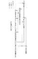
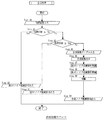
図1は、第1の実施形態の構成図である。レンズ系100,絞り101,CCD102を介して撮影された映像信号は、増幅器(以下、"Gain")104にて増幅され、A/Dコンバータ(以下、"A/D")105にてデジタル信号へ変換される。A/D105からの映像信号は、バッファ106を介して色信号分離抽出部111へ転送される。
First Embodiment [Configuration]
FIG. 1 is a configuration diagram of the first embodiment. A video signal photographed through the
バッファ106は、プリホワイトバランス調整部(以下、"PreWB部")107,測光評価部108,合焦点検出部109へも接続されている。PreWB部107はGain104へ、測光評価部108は絞り101,CCD102,Gain104へ、合焦点検出部109はAFモータ110へ接続されている。色信号分離抽出部111は第1ノイズ低減部112および第2ノイズ低減部113へ接続されている。第1ノイズ低減部112および第2ノイズ低減部113は、合成部114,信号処理部115を介してメモリーカードなどの出力部116に接続されている。
The buffer 106 is also connected to a pre-white balance adjustment unit (hereinafter “PreWB unit”) 107, a photometric evaluation unit 108, and a focus detection unit 109. The PreWB unit 107 is connected to the Gain 104, the photometric evaluation unit 108 is connected to the
マイクロコンピュータなどの制御部117は、Gain104,A/D105,PreWB部107,測光評価部108,合焦点検出部109,色信号分離抽出部111,第1ノイズ低減部112,第2ノイズ低減部113,合成部114,信号処理部115,出力部116と双方向に接続されている。また、電源スイッチ,シャッターボタン,撮影時の各種モードの切り替えの設定を行うためのインターフェースを備えた外部I/F部118も制御部117に双方向に接続されている。さらに、CCD102の近傍に配置された温度センサー103からの信号は制御部117へ接続されている。
A control unit 117 such as a microcomputer includes Gain 104, A /
[作用]
図1において、映像信号の流れを説明する。外部I/F部118を介してISO感度などの撮影条件を設定した後、シャッターボタンを半押しにすることでプリ撮像モードに入る。レンズ系100,絞り101,CCD102を介して撮影された映像信号はアナログ信号として出力される。なお、第1の実施形態においてはCCD102としてベイヤー(Bayer)型原色フィルタを前面に配置した単板CCDを想定する。
[Action]
In FIG. 1, the flow of the video signal will be described. After setting shooting conditions such as ISO sensitivity via the external I / F unit 118, the pre-shooting mode is entered by pressing the shutter button halfway. A video signal photographed through the
図2(a)は、ベイヤー型原色フィルタの構成を示す。ベイヤー型は2×2画素を基本単位とし、赤(R),青(B)フィルタが1画素ずつ、緑(Gr,Gb)フィルタが2画素配置される。なお、緑フィルタは同一な特性であるが、第1の実施形態では処理の便宜上これをGrとGbに区別するものとする。 FIG. 2A shows the configuration of the Bayer-type primary color filter. The Bayer type has 2 × 2 pixels as a basic unit, in which red (R) and blue (B) filters are arranged one pixel at a time, and two green (Gr, Gb) filters are arranged. The green filter has the same characteristics, but in the first embodiment, this is distinguished from Gr and Gb for convenience of processing.
上記アナログ信号はGain104にて所定量増幅され、A/D105にてデジタル信号へ変換されてバッファ106へ転送される。バッファ106内の映像信号は、制御部117の制御に基づき、PreWB部107および測光評価部108および合焦点検出部109へ転送される。
The analog signal is amplified by a predetermined amount at Gain 104, converted to a digital signal by A /
PreWB部107では所定レベルの信号を色フィルタに対応する色信号ごとに積算することで、簡易ホワイトバランス係数を算出する。上記係数をGain104へ転送し、色信号ごとに異なるゲインを乗算させることでホワイトバランスを行わせる。 The PreWB unit 107 calculates a simple white balance coefficient by integrating signals of a predetermined level for each color signal corresponding to the color filter. The above coefficients are transferred to Gain 104, and white balance is performed by multiplying a different gain for each color signal.
測光評価部108では、設定されたISO感度,手ぶれ限界のシャッター速度などを加味し、適正露光となるよう絞り101やCCD102の電子シャッター速度やGain104の増幅率などを制御する。
The photometric evaluation unit 108 controls the electronic shutter speed of the
また、合焦点検出部109では、映像信号中のエッジ強度を検出し、これが最大となるようにAFモータ110を制御することで合焦信号を得る。 Further, the focus detection unit 109 detects the edge intensity in the video signal and controls the AF motor 110 so as to maximize the edge intensity, thereby obtaining a focus signal.
次に、外部I/F部118を介してシャッターボタンを全押しにすることにより本撮影が行われ、映像信号はプリ撮像と同様にバッファ106へ転送される。本撮影は、PreWB部107にて求められた簡易ホワイトバランス係数、測光評価部108にて求められた露光条件、合焦点検出部109にて求められた合焦条件に基づき行われ、これらの撮影時の条件は制御部117へ転送される。また、バッファ106内の映像信号は色信号分離抽出部111へ転送される。 Next, full shooting is performed by fully pressing the shutter button via the external I / F unit 118, and the video signal is transferred to the buffer 106 in the same manner as the pre-shooting. The actual photographing is performed based on the simple white balance coefficient obtained by the PreWB unit 107, the exposure condition obtained by the photometric evaluation unit 108, and the focusing condition obtained by the in-focus detection unit 109. The time condition is transferred to the control unit 117. The video signal in the buffer 106 is transferred to the color signal separation / extraction unit 111.
色信号分離抽出部111は、制御部117の制御に基づき、以後のノイズ低減処理の対象となる注目画素および注目画素の近傍に位置する近傍画素からなる局所領域を色信号ごとに順次抽出する。第1の実施形態においては、例えば図2(a)に示される10×10画素を基本単位として映像信号から抽出する。この場合、ノイズ低減処理の対象となる注目画素はR22,Gr22,Gb22,B22の4画素となる。 Based on the control of the control unit 117, the color signal separation / extraction unit 111 sequentially extracts a local region including a target pixel to be subjected to subsequent noise reduction processing and neighboring pixels located in the vicinity of the target pixel for each color signal. In the first embodiment, for example, 10 × 10 pixels shown in FIG. 2A are extracted from the video signal as a basic unit. In this case, the target pixel to be subjected to the noise reduction process is four pixels R 22 , Gr 22 , Gb 22 , and B 22 .
次に、図2(b)に示されるようにR,Gr,Gb,Bの色フィルタごとに5×5画素の局所領域として分離する。以降は、局所領域内の画素をCij(Cは色信号でC=R,Gr,Gb,B、iはX座標でi=0〜4、jはY座標でj=0〜4)で表記する。5×5画素の局所領域の場合は、注目画素はC22となる。映像信号からもれなく注目画素を抽出するために、図2(a)に示される10×10画素の基本単位は4行4列ずつ重複して順次抽出されることになる。抽出された局所領域は、第1ノイズ低減部112および第2ノイズ低減部113へ転送される。 Next, as shown in FIG. 2B, each R, Gr, Gb, B color filter is separated as a local region of 5 × 5 pixels. Thereafter, the pixels in the local area are represented by C ij (C is a color signal, C = R, Gr, Gb, B, i is an X coordinate, i = 0-4, and j is a Y coordinate, j = 0-4) write. The 5 × 5 cases of local region of pixels, the target pixel becomes C 22. In order to extract the pixel of interest from the video signal, the basic unit of 10 × 10 pixels shown in FIG. 2 (a) is sequentially extracted by overlapping four rows and four columns. The extracted local region is transferred to the first noise reduction unit 112 and the second noise reduction unit 113.
第1ノイズ低減部112は、制御部117の制御に基づき、局所領域の低周波成分から注目画素C22に関するランダム性のノイズ量N22を推定する。その後、局所領域の低周波成分および推定されたノイズ量N22を用いて注目画素C22にコアリング処理を行うことでランダム性のノイズ低減処理を行う。以降は、第1ノイズ低減部112にてランダム性のノイズ低減処理がなされた注目画素をCN1 22で記述する。ランダム性のノイズ低減処理がなされた注目画素CN1 22は、合成部114へ転送される。 Based on the control of the control unit 117, the first noise reduction unit 112 estimates the random noise amount N 22 related to the target pixel C 22 from the low frequency components in the local region. Thereafter, a random noise reduction process is performed by performing a coring process on the target pixel C 22 using the low frequency component of the local region and the estimated noise amount N 22 . Hereinafter, the target pixel on which random noise reduction processing has been performed by the first noise reduction unit 112 is described as C N1 22 . The target pixel C N1 22 that has been subjected to random noise reduction processing is transferred to the synthesis unit 114.
一方、第2ノイズ低減部113は、制御部117の制御に基づき、局所領域からインパルス性のノイズの度合いを示す指標係数ICを注目画素C22およびその近傍8画素C11,C21,C31,C12,C32,C13,C23,C33に関して算出する。以後、注目画素C22の指標係数をIC0で、近傍8画素の指標係数をIC1〜IC8で、指標係数全体をICk(k=0〜8)で表記する。また、必要に応じて注目画素C22をC0で、近傍8画素をC1〜C8で、全9画素をCkとして簡略化して表記する。 On the other hand, based on the control of the control unit 117, the second noise reduction unit 113 sets the index coefficient IC indicating the degree of impulsive noise from the local region to the target pixel C 22 and its neighboring eight pixels C 11 , C 21 , C 31. , C 12 , C 32 , C 13 , C 23 , C 33 are calculated. Hereinafter, the index coefficient of the pixel of interest C 22 is denoted by IC 0 , the index coefficients of the neighboring 8 pixels are denoted by IC 1 to IC 8 , and the entire index coefficient is denoted by IC k (k = 0 to 8). Further, if necessary, the pixel of interest C 22 is simply expressed as C 0 , the neighboring 8 pixels as C 1 to C 8 , and all 9 pixels as C k .
その後、指標係数ICkを用いて注目画素およびその近傍8画素の重み係数を求め、重み付けフィルタ処理を行うことでインパルス性のノイズ低減処理を行う。以降は、第2ノイズ低減部113にてインパルス性のノイズ低減処理がなされた注目画素をCN2 22で記述する。注目画素C22の指標係数IC0およびインパルス性のノイズ低減処理がなされた注目画素をCN2 22は、合成部114へ転送される。 Thereafter, the weight coefficient of the pixel of interest and its neighboring eight pixels is obtained using the index coefficient IC k and the impulsive noise reduction process is performed by performing the weighting filter process. Hereinafter, the pixel of interest that has been subjected to the impulsive noise reduction processing by the second noise reduction unit 113 is described as C N2 22 . C N2 22 is transferred to the synthesizing unit 114 as an index coefficient IC 0 of the pixel of interest C 22 and the pixel of interest subjected to the impulsive noise reduction process.
合成部114は、制御部117の制御に基づき、第2ノイズ低減部113から転送される指標係数IC0を用いて第1ノイズ低減部112にてランダム性のノイズ低減処理がなされた注目画素をCN1 22およびインパルス性のノイズ低減処理がなされた注目画素CN2 22を合成処理し、合成後の注目画素CN 22を求める。 Based on the control of the control unit 117, the synthesis unit 114 uses the index coefficient IC 0 transferred from the second noise reduction unit 113 to select a target pixel that has been subjected to random noise reduction processing by the first noise reduction unit 112. C N1 22 and the target pixel C N2 22 that has been subjected to the impulsive noise reduction process are synthesized, and the synthesized target pixel C N 22 is obtained.

信号処理部115では、制御部117の制御に基づき、合成処理がなされたノイズ低減後の映像信号に対して、公知の補間処理,強調処理および圧縮処理などを行い、出力部116へ転送する。 Based on the control of the control unit 117, the signal processing unit 115 performs known interpolation processing, enhancement processing, compression processing, and the like on the noise-reduced video signal that has been subjected to the synthesis processing, and transfers it to the output unit 116.
出力部116は、磁気ディスクやメモリーカードなどの記録媒体に映像信号を記録保存する。 The output unit 116 records and stores the video signal in a recording medium such as a magnetic disk or a memory card.
図3は第1ノイズ低減部112の構成の一例を示すもので、バッファ200,平均値算出部201,ゲイン算出部202,標準値付与部203,パラメータ用ROM204,パラメータ選択部205,ノイズ補間部206,コアリング部207からなる。 FIG. 3 shows an example of the configuration of the first noise reduction unit 112. The buffer 200, the average value calculation unit 201, the gain calculation unit 202, the standard value assignment unit 203, the parameter ROM 204, the parameter selection unit 205, and the noise interpolation unit 206 and a coring unit 207.
色信号分離抽出部111は、バッファ200を介して平均値算出部201へ接続している。平均値算出部201は、パラメータ選択部205およびコアリング部207へ接続している。ゲイン算出部202,標準値付与部203,パラメータ用ROM204は、パラメータ選択部205へ接続している。パラメータ選択部205は、ノイズ補間部206を介してコアリング部207へ接続している。コアリング部207は、合成部114へ接続している。制御部117は、平均値算出部201,ゲイン算出部202,標準値付与部203,パラメータ選択部205,ノイズ補間部206,コアリング部207と双方向に接続されている。 The color signal separation / extraction unit 111 is connected to the average value calculation unit 201 via the buffer 200. Average value calculating section 201 is connected to parameter selecting section 205 and coring section 207. The gain calculation unit 202, the standard value assigning unit 203, and the parameter ROM 204 are connected to the parameter selection unit 205. The parameter selection unit 205 is connected to the coring unit 207 via the noise interpolation unit 206. The coring unit 207 is connected to the combining unit 114. The control unit 117 is bidirectionally connected to the average value calculation unit 201, the gain calculation unit 202, the standard value assigning unit 203, the parameter selection unit 205, the noise interpolation unit 206, and the coring unit 207.
色信号分離抽出部111から図2(b)に示されるように、R,Gr,Gb,Bの色フィルタごとに5×5画素の局所領域が順次バッファ200へ転送されてくる。 As shown in FIG. 2B, the 5 × 5 pixel local area is sequentially transferred from the color signal separation / extraction unit 111 to the buffer 200 for each of the R, Gr, Gb, and B color filters.
平均値算出部201は、制御部117の制御に基づき、(2)式に示されるように局所領域の平均値C_AV(C= R,Gr,Gb,B)を算出する。 Based on the control of the control unit 117, the average value calculation unit 201 calculates the average value C_AV (C = R, Gr, Gb, B) of the local region as shown in the equation (2).
ゲイン算出部202は、制御部117から転送されるISO感度および露光条件に関する情報に基づきGain104における増幅量を求め、パラメータ選択部205へ転送する。また、制御部117は温度センサー103からCCD102の温度情報を得て、これをパラメータ選択部205へ転送する。
The gain calculation unit 202 obtains the amplification amount in the
パラメータ選択部205は、平均値算出部201からの局所領域の平均値,ゲイン算出部202からのゲインの情報,制御部117からの温度情報に基づき注目画素C22に関するランダム性のノイズ量N22を推定する。 Parameter selection unit 205, the average value of the local area from the average value calculator 201, the gain information from the gain calculation unit 202, a noise amount of randomness about the target pixel C 22 on the basis of the temperature information from the control unit 117 N 22 Is estimated.
図4は、ランダム性のノイズ量の推定に関する説明図である。図4(a)は、信号レベルLに対するランダム性のノイズ量Nをプロットしたもので、信号レベルに対して2次曲線的に増加している。図4(a)を2次関数でモデル化すると(3)式が得られる。 FIG. 4 is an explanatory diagram regarding estimation of random noise amount. FIG. 4A is a plot of the random noise amount N against the signal level L, which increases in a quadratic curve with respect to the signal level. When FIG. 4A is modeled by a quadratic function, equation (3) is obtained.
![]()
![]()
![]()
![]()
ここで、αgt,βgt,γgtは定数項である。ただし、(4)式の関数を複数記録し、その都度演算によりノイズ量を算出することは処理的に煩雑である。このため、図4(b)に示すようなモデルの簡略化を行う。図4(b)においては、最大のノイズ量を与えるモデルを基準ノイズモデルとして選択し、これを所定数の折れ線で近似する。折れ線の変曲点は、信号レベルLとノイズ量Nからなる座標データ(Ln, Nn)で表す。ここで、nは変曲点の数を示す。 Here, α gt , β gt , and γ gt are constant terms. However, it is cumbersome in terms of processing to record a plurality of functions of the equation (4) and calculate the noise amount by calculation each time. For this reason, the model as shown in FIG. 4B is simplified. In FIG. 4B, a model that gives the maximum amount of noise is selected as a reference noise model, and this is approximated by a predetermined number of broken lines. The inflection point of the broken line is represented by coordinate data (L n , N n ) composed of the signal level L and the noise amount N. Here, n indicates the number of inflection points.
また、上記基準ノイズモデルから他のノイズモデルを導出するための補正係数kgtも用意される。補正係数kgtは、各ノイズモデルと基準ノイズモデル間から最小自乗法により算出される。基準ノイズモデルから他のノイズモデルを導出するには、上記補正係数kgtを乗算することで行われる。上記基準ノイズモデルの座標データ(Ln, Nn)および補正係数kgtは、事前に撮像系の特性を計測することで容易に得ることができる。基準ノイズモデルの座標データ(Ln, Nn)および補正係数kgtは、パラメータ用ROM204に記録される。 A correction coefficient k gt for deriving another noise model from the reference noise model is also prepared. The correction coefficient k gt is calculated by the least square method from between each noise model and the reference noise model. In order to derive another noise model from the reference noise model, the correction coefficient k gt is multiplied. The coordinate data (L n , N n ) and the correction coefficient k gt of the reference noise model can be easily obtained by measuring the characteristics of the imaging system in advance. The coordinate data (L n , N n ) and the correction coefficient k gt of the reference noise model are recorded in the parameter ROM 204.
図4(c)は、図4(b)に示す簡易化されたノイズモデルからノイズ量を算出する方法を示す。例えば、与えられた信号レベルl、ゲインがg、温度がtに対応するノイズ量Nを求めることを想定する。まず、信号レベルlが基準ノイズモデルのどの区間に属するかを探索する。ここでは、(Ln, Nn)と(Ln+1, Nn+1)間の区間に属するとする。基準ノイズモデルにおける基準ノイズ量Nlを線形補間にて求める。 FIG. 4C shows a method for calculating the noise amount from the simplified noise model shown in FIG. For example, assume that a noise amount N corresponding to a given signal level l, gain g, and temperature t is obtained. First, it is searched to which section of the reference noise model the signal level l belongs. Here, it is assumed that it belongs to the section between (L n , N n ) and (L n + 1 , N n + 1 ). The reference noise amount N l in the reference noise model is obtained by linear interpolation.
![]()
![]()
![]()
![]()
ノイズ補間部206は、制御部117の制御に基づき、パラメータ選択部205からの信号レベルlおよび区間の座標データ(Ln, Nn)と(Ln+1, Nn+1)から(5)式に基づき基準ノイズモデルにおける基準ノイズ量Nlを算出する。その後、パラメータ選択部205からの補正係数kgから(6)式に基づきノイズ量Nを算出する。算出されたノイズ量Nは、図2(b)に示される局所領域の場合、注目画素C22のノイズ量N22としてコアリング部207へ転送される。 Based on the control of the control unit 117, the noise interpolation unit 206 calculates (5) from the signal level l from the parameter selection unit 205 and the coordinate data (L n , N n ) and (L n + 1 , N n + 1 ) of the section. The reference noise amount N l in the reference noise model is calculated based on the formula (1). Thereafter, the noise amount N is calculated from the correction coefficient k g from the parameter selection unit 205 based on the equation (6). In the case of the local region shown in FIG. 2B, the calculated noise amount N is transferred to the coring unit 207 as the noise amount N 22 of the target pixel C 22 .
なお、上記ノイズ量算出の過程において、温度t,ゲインgなどの情報を撮影ごとに求める必要はない。任意の情報を標準値付与部203に記録させておき、算出過程を省略する構成も可能である。これにより、高速処理や省電力化などが実現できる。 In the process of calculating the amount of noise, it is not necessary to obtain information such as temperature t and gain g for each image. A configuration in which arbitrary information is recorded in the standard value assigning unit 203 and the calculation process is omitted is also possible. Thereby, high-speed processing and power saving can be realized.
コアリング部207は、制御部117の制御に基づき、平均値算出部201から注目画素C22および平均値C_AVをノイズ補間部206からノイズ量N22を読み込み、注目画素C22に関してコアリング処理を行いランダム性のノイズ低減処理がなされた注目画素をCN1 22を求める。 Based on the control of the control unit 117, the coring unit 207 reads the target pixel C 22 and the average value C_AV from the average value calculation unit 201 and the noise amount N 22 from the noise interpolation unit 206, and performs coring processing on the target pixel C 22. C N1 22 is obtained for the target pixel that has been subjected to random noise reduction processing.
なお、上記構成では局所領域の低周波成分として平均値算出を、ノイズ推定処理に補間処理を用いる構成となっていたが、このような構成に限定される必要はない。例えば、局所領域の低周波成分としてローパスフィルタ処理を、ノイズ推定処理にルックアップテーブルを用いる構成も可能である。 In the above configuration, the average value is calculated as the low frequency component of the local region and the interpolation processing is used for the noise estimation processing. However, the configuration is not limited to this configuration. For example, a configuration in which low-pass filter processing is used as a low frequency component in the local region and a lookup table is used in noise estimation processing is also possible.
図5は、第1ノイズ低減部112の別構成の一例を示すもので、図2に示す平均値算出部201,パラメータ用ROM204,パラメータ選択部205,ノイズ補間部206を削除し、ローパスフィルタ部208,ノイズテーブル部209を追加した構成になっている。基本構成は図3に示す第1ノイズ低減部112と同等であり、同一の構成には同一の名称と番号を割り当てている。以下、異なる部分のみ説明する。 FIG. 5 shows an example of another configuration of the first noise reduction unit 112. The average value calculation unit 201, the parameter ROM 204, the parameter selection unit 205, and the noise interpolation unit 206 shown in FIG. 208 and a noise table unit 209 are added. The basic configuration is equivalent to the first noise reduction unit 112 shown in FIG. 3, and the same name and number are assigned to the same configuration. Only different parts will be described below.
色信号分離抽出部111は、バッファ200を介してローパスフィルタ部208へ接続している。ローパスフィルタ部208は、ノイズテーブル部209およびコアリング部207へ接続している。ゲイン算出部202,標準値付与部203は、ノイズテーブル部209へ接続している。ノイズテーブル部209は、コアリング部207へ接続している。制御部117は、ローパスフィルタ部208,ノイズテーブル部209と双方向に接続されている。 The color signal separation / extraction unit 111 is connected to the low-pass filter unit 208 via the buffer 200. The low-pass filter unit 208 is connected to the noise table unit 209 and the coring unit 207. The gain calculation unit 202 and the standard value giving unit 203 are connected to the noise table unit 209. The noise table unit 209 is connected to the coring unit 207. The control unit 117 is bidirectionally connected to the low-pass filter unit 208 and the noise table unit 209.
ローパスフィルタ部208は、制御部117の制御に基づき、所定の周波数特性を有するローパスフィルタ処理を局所領域に対して行い、局所領域の低周波成分C_LO(C= R,Gr,Gb,B)を算出する。算出された低周波成分C_LOはノイズテーブル部209へ、低周波成分C_LOおよび注目画素C22はコアリング部207へ転送される。ローパスフィルタ部208からの局所領域の低周波成分C_LO、ゲイン算出部202からのゲイン情報、制御部117からの温度情報はノイズテーブル部209へ転送される。 Based on the control of the control unit 117, the low-pass filter unit 208 performs low-pass filter processing having a predetermined frequency characteristic on the local region, and generates a low-frequency component C_LO (C = R, Gr, Gb, B) in the local region. calculate. Low-frequency component C_LO calculated in the noise table unit 209, the low-frequency component C_LO and the target pixel C 22 are transferred to the coring unit 207. The low frequency component C_LO of the local region from the low pass filter unit 208, the gain information from the gain calculation unit 202, and the temperature information from the control unit 117 are transferred to the noise table unit 209.
ノイズテーブル部209は、ローパスフィルタ部208からの局所領域に関する低周波成分,ゲイン算出部202からのゲイン情報,制御部117からの温度情報に基づき注目画素C22のノイズ量N22を出力する。ノイズテーブル部209は、温度,信号値レベル,ゲインとノイズ量間の関係を記録したルックアップテーブルで、(4)式に示される関係に基づき構築される。ノイズテーブル部209で得られたノイズ量N22は、コアリング部207へ転送される。 The noise table unit 209 outputs the noise amount N 22 of the target pixel C 22 based on the low frequency component related to the local region from the low pass filter unit 208, the gain information from the gain calculation unit 202, and the temperature information from the control unit 117. The noise table unit 209 is a look-up table that records the relationship among temperature, signal value level, gain, and noise amount, and is constructed based on the relationship shown in equation (4). The noise amount N 22 obtained by the noise table unit 209 is transferred to the coring unit 207.
コアリング部207は、制御部117の制御に基づき、ローパスフィルタ部208から注目画素C22および低周波成分C_LOをノイズテーブル部209からノイズ量N22を読み込み、注目画素C22に関してコアリング処理を行いランダム性のノイズ低減処理がなされた注目画素をCN1 22を求める。このコアリング処理は、(7)式における平均値C_AVを低周波成分C_LOに置換することで行われる。 Based on the control of the control unit 117, the coring unit 207 reads the target pixel C 22 and the low-frequency component C_LO from the low-pass filter unit 208, reads the noise amount N 22 from the noise table unit 209, and performs coring processing on the target pixel C 22. C N1 22 is obtained for the target pixel that has been subjected to random noise reduction processing. This coring process is performed by replacing the average value C_AV in the equation (7) with the low frequency component C_LO.
図6は第2ノイズ低減部113の構成の一例を示すもので、バッファ300,差分算出部301,バッファ302,ソート部303,総和算出部304,重み係数テーブル部305,バッファ306,重み付けフィルタ部307からなる。 FIG. 6 shows an example of the configuration of the second noise reduction unit 113. The buffer 300, the difference calculation unit 301, the buffer 302, the sort unit 303, the sum calculation unit 304, the weight coefficient table unit 305, the buffer 306, and the weighting filter unit 307.
色信号分離抽出部111は、バッファ300を介して差分算出部301および重み付けフィルタ部307へ接続している。差分算出部301は、バッファ302,ソート部303を介して総和算出部304へ接続している。総和算出部304は、重み係数テーブル部305および合成部114へ接続している。重み係数テーブル部305は、バッファ306を介して重み付けフィルタ部307へ接続している。重み付けフィルタ部307は、合成部114へ接続している。制御部117は、差分算出部301,ソート部303,総和算出部304,重み係数テーブル部305,重み付けフィルタ部307と双方向に接続されている。 The color signal separation / extraction unit 111 is connected to the difference calculation unit 301 and the weighting filter unit 307 via the buffer 300. The difference calculation unit 301 is connected to the sum calculation unit 304 via the buffer 302 and the sort unit 303. The sum total calculation unit 304 is connected to the weighting coefficient table unit 305 and the synthesis unit 114. The weighting coefficient table unit 305 is connected to the weighting filter unit 307 via the buffer 306. The weighting filter unit 307 is connected to the combining unit 114. The control unit 117 is bi-directionally connected to the difference calculation unit 301, the sort unit 303, the sum calculation unit 304, the weighting coefficient table unit 305, and the weighting filter unit 307.
色信号分離抽出部111から図2(b)に示されるように、R,Gr,Gb,Bの色フィルタごとに5×5画素の局所領域が順次バッファ300へ転送されてくる。 As shown in FIG. 2B, the 5 × 5 pixel local area is sequentially transferred from the color signal separation / extraction unit 111 to the buffer 300 for each of R, Gr, Gb, and B color filters.
差分算出部301は、制御部117の制御に基づき、注目画素C22およびその近傍8画素C11,C21,C31,C12,C32,C13,C23,C33の計9画素に関して、各々の近傍8画素との差の絶対値を算出する。
Difference calculation unit 301, based on the control of the control unit 117, a total of nine pixels of the target pixel C 22 and its neighboring eight pixels C 11, C 21, C 31 , C 12,
図7(a)は、局所領域における注目画素C22およびその近傍8画素C11,C21,C31,C12,C32,C13,C23,C33の配置を示す。差分算出部301は、この9画素の個々に対して、近傍8画素との差の絶対値Δを算出する。図7(b)は、差の絶対値Δを算出する画素の配置を示す。例えばC11画素の場合、差の絶対値Δは(8)式で示される。 FIG. 7A shows the arrangement of the target pixel C 22 and its neighboring eight pixels C 11 , C 21 , C 31 , C 12 , C 32 , C 13 , C 23 , and C 33 in the local region. The difference calculation unit 301 calculates the absolute value Δ of the difference from the neighboring 8 pixels for each of the 9 pixels. FIG. 7B shows an arrangement of pixels for calculating the absolute value Δ of the difference. For example, in the case of C 11 pixels, the absolute value Δ of the difference represented by the equation (8).
ソート部303は、制御部117の制御に基づき、バッファ302の差の絶対値をΔlを昇順にソートし、小さい方から所定数、第1の実施形態においては4個を総和算出部304へ転送する。以降は、昇順にソートされた差の絶対値をSΔm(m=1〜8)で表記する。 Sorting unit 303, under the control of the control unit 117 sorts the absolute value of the difference between the buffer 302 the delta l in ascending order, a predetermined number from the smallest, in the first embodiment four to total sum calculation unit 304 Forward. Thereafter, it denoted the absolute value of the sorted in ascending order by the difference SΔ m (m = 1~8).
総和算出部304は、制御部117の制御に基づき、ソート部303から転送される昇順にソートされた4個の差の絶対値の総和を求める。この総和は、指標指数ICとなる。 Based on the control of the control unit 117, the total calculation unit 304 obtains the sum of the absolute values of the four differences sorted in the ascending order transferred from the sorting unit 303. This sum is the index index IC.
![]()
![]()
重み係数テーブル部305は、指標係数ICに基づき後段の重み付きフィルタ処理に使用する重み係数Fを出力するルックアップテーブルである。これは、(10)に基づき構築される。 The weighting coefficient table unit 305 is a look-up table that outputs a weighting coefficient F used for subsequent weighted filter processing based on the index coefficient IC. This is constructed based on (10).
![]()
![]()
重み付けフィルタ部307は、制御部117の制御に基づき、バッファ300から局所領域中の注目画素およびその近傍8画素を、バッファ306から重み係数Fkを読み込み、重み付けフィルタ処理を行う。ここで、注目画素C22をC0で、近傍8画素をC1〜C8で、全9画素をCkとして簡略化して表記する。(11)式に示される重み付けフィルタ処理により、インパルス性のノイズ低減処理がなされた注目画素CN2 22が得られる。 Weighting filter 307, based on the control of the control unit 117, the pixel of interest and its neighboring eight pixels in the local area from the buffer 300, reads the weighting coefficient F k from the buffer 306, performs the weighting filtering. Here, the pixel of interest C 22 is simply expressed as C 0 , the neighboring 8 pixels as C 1 to C 8 , and all 9 pixels as C k . The target pixel C N2 22 that has been subjected to the impulsive noise reduction process is obtained by the weighting filter process represented by the equation (11).
なお、図6に示す第2ノイズ低減部113は、指標指数の算出において差の絶対値を昇順にソートし小さい方から所定数の総和をとり、インパルス性のノイズ低減処理として重み付けフィルタ処理を行う構成となっていたが、このような構成に限定される必要はない。例えば、図8に示されるように指標指数の算出において差の絶対値の全てから総和をとる構成や、インパルス性のノイズ低減処理としてメディアンフィルタなどの非線形フィルタ処理を行う構成も可能である。 The second noise reduction unit 113 shown in FIG. 6 sorts the absolute values of the differences in ascending order in calculating the index index, takes a predetermined number of sums from the smallest, and performs weighting filter processing as impulsive noise reduction processing. Although it has become a configuration, it is not necessary to be limited to such a configuration. For example, as shown in FIG. 8, a configuration in which the sum of all the absolute values of the differences is calculated in calculating the index index, or a configuration in which nonlinear filter processing such as a median filter is performed as impulsive noise reduction processing is possible.
図8は第2ノイズ低減部113の別構成の一例を示すもので、図6に示す第2ノイズ低減部113からバッファ302,ソート部303,重み係数テーブル部305,バッファ306,重み付けフィルタ部307が省略され、注目画素読み出し部308,メディアンフィルタ部309,切り換え部310が追加された構成になっている。基本構成は図6に示す第2ノイズ低減部113と同等であり、同一の構成には同一の名称と番号を割り当てている。以下、異なる部分のみ説明する。 FIG. 8 shows an example of another configuration of the second noise reduction unit 113. The second noise reduction unit 113 shown in FIG. 6 is replaced with a buffer 302, a sorting unit 303, a weighting coefficient table unit 305, a buffer 306, and a weighting filter unit 307. Is omitted, and a pixel-of-interest readout unit 308, a median filter unit 309, and a switching unit 310 are added. The basic configuration is the same as the second noise reduction unit 113 shown in FIG. 6, and the same name and number are assigned to the same configuration. Only different parts will be described below.
バッファ300は、差分算出部301,注目画素読み出し部308,メディアンフィルタ部309へ接続している。差分算出部301は、総和算出部304へ接続している。総和算出部304は、切り換え部310および合成部114へ接続している。注目画素読み出し部308およびメディアンフィルタ部309は、切り換え部310へ接続している。切り換え部310は、合成部114へ接続している。制御部117は、注目画素読み出し部308,メディアンフィルタ部309,切り換え部310と双方向に接続されている。 The buffer 300 is connected to the difference calculation unit 301, the target pixel reading unit 308, and the median filter unit 309. The difference calculation unit 301 is connected to the sum calculation unit 304. The total calculation unit 304 is connected to the switching unit 310 and the combining unit 114. The target pixel readout unit 308 and the median filter unit 309 are connected to the switching unit 310. The switching unit 310 is connected to the combining unit 114. The control unit 117 is bi-directionally connected to the target pixel reading unit 308, the median filter unit 309, and the switching unit 310.
差分算出部301は、制御部117の制御に基づき、注目画素C22に関して近傍8画素との差の絶対値Δlを算出する。算出された差の絶対値Δlは、総和算出部304へ転送される。 Difference calculation unit 301, based on the control of the control unit 117 calculates an absolute value delta l of the difference between the neighboring eight pixels with respect to the target pixel C 22. Absolute value delta l of the calculated differences is transferred to the total sum calculation unit 304.
総和算出部304は、制御部117の制御に基づき、差の絶対値Δlの総和を求める。この総和は、注目画素C22に関する指標指数IC0となる。 Total sum calculation unit 304, based on the control of the control unit 117, obtaining the sum of the absolute values delta l of the difference. This sum is an index index IC 0 regarding the target pixel C 22 .
![]()
![]()
注目画素読み出し部308は、制御部117の制御に基づき、バッファ300から注目画素C22を読み出し、切り換え部310へ転送する。 The target pixel reading unit 308 reads the target pixel C 22 from the buffer 300 based on the control of the control unit 117 and transfers it to the switching unit 310.
メディアンフィルタ部309は、制御部117の制御に基づき、バッファ300から局所領域を読み出し、公知のメディアンフィルタ処理を行い、注目画素C22に関する処理結果MC22を得る。メディアンフィルタ処理結果MC22は、切り換え部310へ転送される。 Median filter unit 309 under the control of the control unit 117 reads the local area from the buffer 300, performs the known median filtering, to obtain a processing result MC 22 relates to the target pixel C 22. The median filter processing result MC 22 is transferred to the switching unit 310.
切り換え部310は、制御部117の制御に基づき、総和算出部304からの指標指数IC0を用いて注目画素読み出し部308からの注目画素C22とメディアンフィルタ部309からのメディアンフィルタ処理結果MC22に関する切り換え制御を行うことにより、インパルス性のノイズ低減処理がなされた注目画素CN2 22が得られる。 Based on the control of the control unit 117, the switching unit 310 uses the index index IC 0 from the sum calculation unit 304 and the target pixel C 22 from the target pixel reading unit 308 and the median filter processing result MC 22 from the median filter unit 309. As a result of the switching control relating to the pixel of interest C N2 22 that has undergone impulsive noise reduction processing, the pixel C N2 22 is obtained.
図9は、合成部114の構成の一例を示すもので、第1信号選択部400,第2信号選択部401,合成係数テーブル部402,乗算部403,乗算部404,加算部405からなる。 FIG. 9 shows an example of the configuration of the synthesis unit 114, which includes a first signal selection unit 400, a second signal selection unit 401, a synthesis coefficient table unit 402, a multiplication unit 403, a multiplication unit 404, and an addition unit 405.
第1ノイズ低減部112は、第1信号選択部400へ接続している。第2ノイズ低減部113は、第1信号選択部400,第2信号選択部401,合成係数テーブル部402へ接続している。第1信号選択部400は、乗算部403および信号処理部115へ接続している。第2信号選択部401は、乗算部404および信号処理部115へ接続している。合成係数テーブル部402は、乗算部403および乗算部404へ接続している。乗算部403および乗算部404は加算部405へ、加算部405は信号処理部115へ接続している。制御部117は、第1信号選択部400,第2信号選択部401,合成係数テーブル部402,乗算部403,乗算部404,加算部405と双方向に接続されている。 The first noise reduction unit 112 is connected to the first signal selection unit 400. The second noise reduction unit 113 is connected to the first signal selection unit 400, the second signal selection unit 401, and the synthesis coefficient table unit 402. The first signal selection unit 400 is connected to the multiplication unit 403 and the signal processing unit 115. The second signal selection unit 401 is connected to the multiplication unit 404 and the signal processing unit 115. The synthesis coefficient table unit 402 is connected to the multiplication unit 403 and the multiplication unit 404. Multiplier 403 and multiplier 404 are connected to adder 405, and adder 405 is connected to signal processor 115. The control unit 117 is bi-directionally connected to the first signal selection unit 400, the second signal selection unit 401, the synthesis coefficient table unit 402, the multiplication unit 403, the multiplication unit 404, and the addition unit 405.
第1信号選択部400は、制御部117の制御に基づき、第2ノイズ低減部113から注目画素C22に関する指標指数IC0を、第1ノイズ低減部112からランダム性のノイズ低減処理がなされた注目画素CN1 22を読み込む。指標指数IC0が所定の閾値Th1以下の場合、注目画素CN1 22を合成後の注目画素CN 22として信号処理部115へ転送する。指標指数IC0が所定の閾値Th1より大きい場合、注目画素CN1 22を乗算部403へ転送する。 Based on the control of the control unit 117, the first signal selection unit 400 is subjected to the index index IC 0 regarding the target pixel C 22 from the second noise reduction unit 113, and the random noise reduction processing from the first noise reduction unit 112. Read the target pixel C N1 22 . When the index index IC 0 is equal to or smaller than the predetermined threshold Th1, the target pixel C N1 22 is transferred to the signal processing unit 115 as the synthesized target pixel C N 22 . When the index index IC 0 is larger than the predetermined threshold Th1, the target pixel C N1 22 is transferred to the multiplication unit 403.
第2信号選択部401は、制御部117の制御に基づき、第2ノイズ低減部113から注目画素C22に関する指標指数IC0およびインパルス性のノイズ低減処理がなされた注目画素CN2 22を読み込む。指標指数IC0が所定の閾値Th2以上の場合、注目画素CN2 22を合成後の注目画素CN 22として信号処理部115へ転送する。指標指数IC0が所定の閾値Th2より小さい場合、注目画素CN2 22を乗算部404へ転送する。 Based on the control of the control unit 117, the second signal selection unit 401 reads from the second noise reduction unit 113 the index index IC 0 related to the target pixel C 22 and the target pixel C N2 22 that has undergone impulsive noise reduction processing. When the index index IC 0 is equal to or greater than the predetermined threshold Th2, the target pixel C N2 22 is transferred to the signal processing unit 115 as the synthesized target pixel C N 22 . When the index index IC 0 is smaller than the predetermined threshold Th2, the target pixel C N2 22 is transferred to the multiplication unit 404.
合成係数テーブル部402は、指標指数IC0に対する合成処理に用いる合成係数w=0〜1および1-wを記録したルックアップテーブルである。図10は、合成係数wに関する説明図で、指標指数IC0≦Th1の場合にw=0で、指標指数IC0≧Th2の場合にw=1で、Th1<IC0<Th2の場合にw=0〜1の線形に変化する特性となっている。合成係数テーブル部402は、合成係数1-wを乗算部403へ、合成係数wを乗算部404へ転送する。 The synthesis coefficient table unit 402 is a look-up table in which synthesis coefficients w = 0 to 1 and 1-w used for the synthesis process for the index index IC 0 are recorded. FIG. 10 is an explanatory diagram relating to the composite coefficient w, where w = 0 when the index index IC 0 ≦ Th1, w = 1 when the index index IC 0 ≧ Th2, and w when Th1 <IC 0 <Th2. The characteristic changes linearly from 0 to 1. The synthesis coefficient table unit 402 transfers the synthesis coefficient 1-w to the multiplication unit 403 and the synthesis coefficient w to the multiplication unit 404.
乗算部403は、制御部117の制御に基づき、第1信号選択部400から注目画素CN1 22が転送されてきた場合、注目画素CN1 22と合成係数1-wを乗算し、その結果(1-w)・CN1 22を加算部405へ転送する。 When the target pixel C N1 22 is transferred from the first signal selection unit 400 based on the control of the control unit 117, the multiplication unit 403 multiplies the target pixel C N1 22 by the synthesis coefficient 1-w, and the result ( 1-w) · C N1 22 is transferred to the adder 405.
乗算部404は、制御部117の制御に基づき、第2信号選択部401から注目画素CN2 22が転送されてきた場合、注目画素CN2 22と合成係数wを乗算し、その結果w・CN2 22を加算部405へ転送する。 When the pixel of interest C N2 22 is transferred from the second signal selection unit 401 based on the control of the control unit 117, the multiplication unit 404 multiplies the pixel of interest C N2 22 by the synthesis coefficient w, and as a result, w · C N2 22 is transferred to the adding unit 405.
加算部405は、制御部117の制御に基づき、乗算部403からの(1-w)・CN1 22および乗算部404からのw・CN2 22を加算処理し、合成後の注目画素CN 22を求める。上記により(1)式に示される合成処理が行われることになる。 Based on the control of the control unit 117, the addition unit 405 adds (1-w) · C N1 22 from the multiplication unit 403 and w · C N2 22 from the multiplication unit 404, and combines the target pixel C N after synthesis. Ask for 22 . As a result, the synthesis process shown in the equation (1) is performed.
[作用]
上記構成により、性質の異なるランダム性のノイズとインパルス性のノイズに対して独立に低減処理を行い、両者をインパルス性の度合いを示す指標係数に基づき合成処理することができる。このため、ランダム性およびインパルス性の両ノイズに対して最適なノイズ低減処理が可能となり高品位な映像信号が得られる。
[Action]
With the above-described configuration, it is possible to perform reduction processing independently on random noise and impulsive noise having different properties, and to combine both based on an index coefficient indicating the degree of impulsiveness. For this reason, it is possible to perform optimum noise reduction processing for both random and impulsive noise, and a high-quality video signal can be obtained.
また2種類のノイズ低減処理に起因する不連続性やアーティファクトの発生を抑制できる。ランダム性のノイズ低減処理は注目画素単位でノイズ量を推定してランダム性のノイズ低減処理を行うため、ノイズ成分のみを高精度に低減することが可能となり、高品位な映像信号が得られる。 In addition, it is possible to suppress the occurrence of discontinuity and artifacts due to two types of noise reduction processing. In the random noise reduction process, the amount of noise is estimated for each pixel of interest and the random noise reduction process is performed. Therefore, only the noise component can be reduced with high accuracy, and a high-quality video signal can be obtained.
ノイズ量の推定に平均値を用いる構成は、実装が容易でありシステムのコスト低減と高速処理が可能となる。一方、ノイズ量の推定にローパスフィルタを用いる構成は、注目画素とその他の画素との重みを制御できるため安定した処理が可能となる。ノイズ量の推定は撮影ごとに異なる条件に動的に適応し、高精度かつ安定的なノイズ量の推定が可能となる。また、ノイズ量の算出に補間演算を用いる構成は、実装が容易であり、システムの低コスト化が可能となる。一方ルックアップテーブルからノイズ量を求める構成は、高速な処理が可能となる。 The configuration using the average value for estimating the amount of noise is easy to implement, and can reduce the cost of the system and perform high-speed processing. On the other hand, the configuration using a low-pass filter for estimating the amount of noise enables stable processing because the weight of the target pixel and other pixels can be controlled. The estimation of the noise amount is dynamically adapted to different conditions for each shooting, and the noise amount can be estimated with high accuracy and stability. Further, the configuration using the interpolation calculation for the calculation of the amount of noise is easy to implement, and the cost of the system can be reduced. On the other hand, the configuration for obtaining the noise amount from the look-up table enables high-speed processing.
また、ランダム性のノイズ低減処理にコアリング処理を用いるため、ノイズ成分のみを重点的に低減でき、かつエッジなどのノイズ以外の画素との連続性が確保できる。 In addition, since the coring process is used for the random noise reduction process, only the noise component can be reduced intensively, and continuity with pixels other than noise such as edges can be secured.
インパルス性のノイズ低減処理において、局所領域の各画素単位でインパルス性の度合いを求め重み付けフィルタ処理を行う構成では、ノイズ成分のみを高精度に低減することが可能となる。また、ルックアップテーブルから重み係数を求める構成では、高速な処理が可能となる。一方、注目画素のみインパルス性の度合いを求め非線形フィルタを行う構成では、処理の高速化が可能となる。また、非線形フィルタ処理としてメディアンフィルタを用いるため、システム全体の低コスト化を可能とする。 In the impulsive noise reduction processing, in the configuration in which the degree of impulsiveness is obtained for each pixel in the local region and the weighting filter processing is performed, it is possible to reduce only the noise component with high accuracy. In addition, in the configuration in which the weight coefficient is obtained from the lookup table, high-speed processing is possible. On the other hand, in the configuration in which only the target pixel obtains the degree of impulsiveness and performs the nonlinear filter, the processing speed can be increased. Further, since the median filter is used as the non-linear filter processing, the cost of the entire system can be reduced.
インパルス性の度合いを示す指標係数において、近傍画素間との差の総和を用いる構成では、処理の高速化と低コストなシステムが提供できる。一方、近傍画素間との差をソートし小さい値からの所定数の総和を用いる構成では、インパルス性のノイズとエッジ部の識別を高精に行うことができ、エッジ部の劣化の少ない高品位な映像信号が得られる。 In the configuration using the sum of differences from neighboring pixels in the index coefficient indicating the degree of impulsiveness, a high-speed processing and a low-cost system can be provided. On the other hand, with the configuration that sorts the difference between neighboring pixels and uses a predetermined number of sums from small values, it is possible to discriminate between impulsive noise and edge portions with high precision, and high quality with little deterioration of edge portions Video signal can be obtained.
また、色信号ごとにノイズ低減処理を行うため、ノイズを高精度に低減することができ、高品位な映像信号が得られる。また、ノイズ低減処理前に補間処理などの前処理が存在しないため、ノイズ低減処理の精度を向上することができる。 Further, since noise reduction processing is performed for each color signal, noise can be reduced with high accuracy, and a high-quality video signal can be obtained. In addition, since there is no preprocessing such as interpolation processing before the noise reduction processing, the accuracy of the noise reduction processing can be improved.
さらに、ベイヤー型原色フィルタは現状の撮像系との親和性が高く、多様なシステムとの組み合わせが可能となる。 Furthermore, the Bayer type primary color filter has a high affinity with the current imaging system, and can be combined with various systems.
[変形例]
なお、第1の実施形態では撮像素子としてベイヤー型原色フィルタを用いる構成となっていたが、このような構成に限定される必要はない。例えば、図2(c)に示される色差線順次型補色フィルタを用いることも可能であるし、二板,三板撮像素子の利用も可能である。
[Modification]
In the first embodiment, the Bayer-type primary color filter is used as the image sensor, but it is not necessary to be limited to such a configuration. For example, the color difference line sequential complementary color filter shown in FIG. 2C can be used, and a two-plate or three-plate image sensor can be used.
図2(c)は、色差線順次型補色フィルタの構成を示す。色差線順次方式は2×2画素を基本単位とし、シアン(Cy),マゼンタ(Mg),イエロー(Ye),緑(G)が1画素ずつ配置される。ただし、MgとGの位置はラインごとに反転している。色差線順次型補色フィルタの場合、色信号分離抽出部111は、図2(c)に示される10×10画素単位で映像信号を読み込み、これを図2(d)に示されるようにMg,G,Ye,Cyの色フィルタごとに、注目画素を中心とする5×5画素を局所領域として分離する。局所領域内の画素値はCij(Cは色信号でC=Mg,G,Ye,Cy)で示されることになる。 FIG. 2C shows the configuration of the color difference line sequential complementary color filter. The color difference line sequential method uses 2 × 2 pixels as a basic unit, and cyan (Cy), magenta (Mg), yellow (Ye), and green (G) are arranged one by one. However, the positions of Mg and G are reversed for each line. In the case of the color difference line sequential complementary color filter, the color signal separation and extraction unit 111 reads the video signal in units of 10 × 10 pixels shown in FIG. 2 (c), and reads the video signal as shown in FIG. For each color filter of G, Ye, and Cy, 5 × 5 pixels centered on the target pixel are separated as local regions. The pixel value in the local area is represented by C ij (C is a color signal, C = Mg, G, Ye, Cy).
さらに、第1の実施形態ではレンズ系100,絞り101,CCD102,温度センサー103,Gain104,A/D105,PreWB部107,測光評価部108,合焦点検出部109,AFモータ110からなる撮像部と一体化した構成になっていたが、このような構成に限定される必要はない。例えば、図11に示されるように、別体の撮像部で撮像された映像信号を未処理のRawデータ形態で、さらにCCD102の色フィルタや撮影時の露光条件などの付随情報をヘッダ部に記録した記録媒体から処理をすることも可能である。
Further, in the first embodiment, an imaging unit including a
図11は、図1に示す構成からレンズ系100,絞り101,CCD102,温度センサー103,Gain104,A/D105,PreWB部107,測光評価部108,合焦点検出部109,AFモータ110を省略し、入力部500,ヘッダ情報解析部501を追加した形態となっている。基本構成は図1と同等であり、同一の構成には同一の名称と番号を割り当てている。以下、異なる部分のみ説明する。
11 omits the
入力部500は、バッファ106およびヘッダ情報解析部501へ接続している。制御部117は、入力部500,ヘッダ情報解析部501と双方向に接続している。 The input unit 500 is connected to the buffer 106 and the header information analysis unit 501. The control unit 117 is bi-directionally connected to the input unit 500 and the header information analysis unit 501.
マウス,キーボードなどの外部I/F部118を介して再生操作を開始することで、記録媒体に保存された映像信号およびヘッダ情報が入力部500から読み込まれる。入力部500からの映像信号はバッファ106へ、ヘッダ情報はヘッダ情報解析部501へ転送される。 By starting the reproduction operation via the external I / F unit 118 such as a mouse or a keyboard, the video signal and header information stored in the recording medium are read from the input unit 500. The video signal from the input unit 500 is transferred to the buffer 106, and the header information is transferred to the header information analysis unit 501.
ヘッダ情報解析部501は、ヘッダ情報から撮影時の情報を抽出して制御部117へ転送する。以後の処理は、図1と同等である。 The header information analysis unit 501 extracts information at the time of shooting from the header information and transfers the information to the control unit 117. The subsequent processing is the same as in FIG.
また、第1の実施形態ではハードウェアによる処理を前提としていたが、このような構成に限定される必要はない。例えば、CCD102からの映像信号を未処理のままのRawデータとして、CCD102の色フィルタや撮影時の露光条件などの付随情報などをヘッダ情報として出力し、別途ソフトウェアにて処理する構成も可能である。図12Aは、信号処理のソフトウェア処理に関するフローを示す。
In the first embodiment, processing based on hardware is assumed. However, it is not necessary to be limited to such a configuration. For example, the video signal from the
ステップS1にて、映像信号および撮影時の露光条件などのヘッダ情報を読み込む。 In step S1, header information such as a video signal and exposure conditions at the time of shooting is read.
ステップS2にて、図2(b)に示されるようにCCD102の色フィルタに基づき、色信号ごとに分離する。
In step S2, separation is performed for each color signal based on the color filter of the
ステップS3にて、図2(b)に示されるようにノイズ低減処理の対象となる注目画素を包含する所定サイズ、例えば5×5画素サイズの局所領域を抽出する。 In step S3, as shown in FIG. 2B, a local area having a predetermined size, for example, a 5 × 5 pixel size, including the target pixel to be subjected to noise reduction processing is extracted.
ステップS4にて、別途説明するようにランダム性のノイズ低減処理となる第1のノイズ低減処理を行う。 In step S4, a first noise reduction process, which is a random noise reduction process, is performed as described separately.
ステップS5にて、別途説明するようにインパルス性のノイズ低減処理となる第2のノイズ低減処理を行う。 In step S5, a second noise reduction process that is an impulsive noise reduction process is performed as described separately.
ステップS6にて、別途説明するように第1のノイズ低減処理がなされた信号と第2のノイズ低減処理がなされた信号を合成する。 In step S6, the signal subjected to the first noise reduction processing and the signal subjected to the second noise reduction processing are synthesized as will be described separately.
ステップS7にて、全ての局所領域が完了したかを判断し、完了していない場合はステップS3へ分岐し、完了した場合はステップS8へ分岐する。 In step S7, it is determined whether or not all the local regions are completed. If not, the process branches to step S3, and if completed, the process branches to step S8.
ステップS8にて、全ての色信号が完了したかを判断し、完了していない場合はステップS2へ分岐し、完了した場合はステップS9へ分岐する。 In step S8, it is determined whether all the color signals are completed. If not completed, the process branches to step S2, and if completed, the process branches to step S9.
ステップS9にて、公知の補間処理、階調変換処理、エッジ強調処理、色強調処理などの信号処理が行われる。 In step S9, known interpolation processing, gradation conversion processing, edge enhancement processing, color enhancement processing, and other signal processing are performed.
ステップS10にて、処理が完了した映像信号が出力され終了する。 In step S10, the processed video signal is output and the process ends.
図12Bは、上記ステップS4における第1のノイズ低減処理に関するフローである。 FIG. 12B is a flow relating to the first noise reduction processing in step S4.
ステップS20にて、(2)式に示されるように局所領域の平均値を算出する。 In step S20, the average value of the local region is calculated as shown in equation (2).
ステップS21にて、読み込まれたヘッダ情報から温度,ゲインなどの情報を設定する。もし、ヘッダ情報に必要なパラメータが存在しない場合は所定の標準値を割り当てる。 In step S21, information such as temperature and gain is set from the read header information. If a necessary parameter does not exist in the header information, a predetermined standard value is assigned.
ステップS22にて、基準ノイズモデルの座標データおよび補正係数を読み込む。 In step S22, the coordinate data and correction coefficient of the reference noise model are read.
ステップS23にて、注目画素が属する基準ノイズモデルの区間の座標データおよび対応する補正係数を選択する。 In step S23, the coordinate data of the section of the reference noise model to which the target pixel belongs and the corresponding correction coefficient are selected.
ステップS24にて、(5),(6)式に示される補間処理にてノイズ量を求める。 In step S24, the amount of noise is obtained by interpolation processing shown in equations (5) and (6).
ステップS25にて、(7)式に示されるコアリング処理にてランダム性のノイズ低減処理がなされた信号を求める。 In step S25, a signal that has undergone random noise reduction processing in the coring processing shown in equation (7) is obtained.
ステップS26にて、第1のノイズ低減処理がなされた信号を出力して終了する。 In step S26, the signal subjected to the first noise reduction process is output and the process ends.
図12Cは、上記ステップS5における第2のノイズ低減処理に関するフローである。 FIG. 12C is a flow relating to the second noise reduction processing in step S5.
ステップS30にて、局所領域内の注目画素および近傍8画素の一つを選択する。 In step S30, one of the target pixel and the neighboring eight pixels in the local region is selected.
ステップS31にて、(8)式に示されるように8個の差の絶対値を算出する。 In step S31, the absolute value of the eight differences is calculated as shown in equation (8).
ステップS32にて、8個の差の絶対値を昇順にソートする。 In step S32, the absolute values of the eight differences are sorted in ascending order.
ステップS33にて、(9)式に示されるように小さい方から所定数、例えば4個の差の絶対値の総和を求め、指標係数とする。 In step S33, a sum of absolute values of a predetermined number, for example, four differences is calculated from the smaller one as shown in the equation (9) and used as an index coefficient.
ステップS34にて、(10)式に基づき構築された指標係数を入力として重み係数を出力するルックアップテーブルを入力する。 In step S34, a look-up table for outputting a weighting coefficient is input with an index coefficient constructed based on equation (10) as an input.
ステップS35にて、指標係数に基づき重み係数を出力する。 In step S35, a weighting coefficient is output based on the index coefficient.
ステップS36にて、注目画素および近傍8画素の全てが選択されたかを判断し、選択が完了していない場合はステップS30へ分岐し、完了した場合はステップS37へ分岐する。 In step S36, it is determined whether all of the target pixel and neighboring 8 pixels have been selected. If selection has not been completed, the process branches to step S30. If completed, the process branches to step S37.
ステップS37にて、(11)式に示される重み付けフィルタ処理を行う。 In step S37, the weighting filter process shown in the equation (11) is performed.
ステップS38にて、重み付けフィルタ処理により得られた信号を第2のノイズ低減処理がなされた信号として出力する。 In step S38, the signal obtained by the weighting filter process is output as a signal subjected to the second noise reduction process.
ステップS39にて、注目画素に関する指標係数を出力して終了する。 In step S39, the index coefficient relating to the target pixel is output and the process ends.
図12Dは、上記ステップS6における合成処理に関するフローである。 FIG. 12D is a flow relating to the composition processing in step S6.
ステップS40にて、注目画素に関する指標係数を入力する。 In step S40, an index coefficient related to the target pixel is input.
ステップS41にて、指標係数と所定の閾値Th1を比較し、指標係数が閾値Th1以下の場合はステップS42へ分岐し、指標係数が閾値Th1より大きい場合はステップS43へ分岐する。 In step S41, the index coefficient is compared with a predetermined threshold Th1, and if the index coefficient is equal to or less than the threshold Th1, the process branches to step S42, and if the index coefficient is greater than the threshold Th1, the process branches to step S43.
ステップS42にて、第1のノイズ低減処理がなされた信号を出力して終了する。 In step S42, the signal subjected to the first noise reduction processing is output and the process ends.
ステップS43にて、指標係数と所定の閾値Th2を比較し、指標係数が閾値Th2以上の場合はステップS44へ分岐し、指標係数が閾値Th2より小さい場合はステップS45へ分岐する。 In step S43, the index coefficient is compared with a predetermined threshold Th2. If the index coefficient is equal to or greater than the threshold Th2, the process branches to step S44. If the index coefficient is smaller than the threshold Th2, the process branches to step S45.
ステップS44にて、第2のノイズ低減処理がなされた信号を出力して終了する。 In step S44, the signal subjected to the second noise reduction process is output and the process ends.
ステップS45にて、図10に示される指標係数を入力として合成係数を出力するルックアップテーブルを入力する。 In step S45, a look-up table for outputting a composite coefficient with the index coefficient shown in FIG. 10 as input is input.
ステップS46にて、指標係数に基づき合成係数を出力する。 In step S46, a composite coefficient is output based on the index coefficient.
ステップS47にて、第1のノイズ低減処理がなされた信号に(1-合成係数)を乗算する。 In step S47, the signal subjected to the first noise reduction process is multiplied by (1-synthesis coefficient).
ステップS48にて、第2のノイズ低減処理がなされた信号に合成係数を乗算する。 In step S48, the signal subjected to the second noise reduction process is multiplied by a synthesis coefficient.
ステップS49にて、第1のノイズ低減処理がなされた信号に(1-合成係数)を乗算した信号と第2のノイズ低減処理がなされた信号に合成係数を乗算した信号を加算する。 In step S49, a signal obtained by multiplying the signal subjected to the first noise reduction process by (1-synthesis coefficient) and a signal obtained by multiplying the signal subjected to the second noise reduction process by the synthesis coefficient are added.
ステップS50にて、合成された信号を出力して終了する。 In step S50, the synthesized signal is output and the process ends.
このように信号処理をソフトウェアにより行う構成としてもよく、ハードウェアにより処理する場合と同じ作用効果が奏される。 As described above, the signal processing may be performed by software, and the same operational effects as in the case of processing by hardware are achieved.
第2の実施形態
[構成]
図13は、第2の実施形態の構成図である。第2の実施形態は、図1に示す第1の実施形態における色信号分離抽出部111が輝度色分離抽出部600へ、第1ノイズ低減部112が第1ノイズ低減部601へ、第2ノイズ低減部113が第2ノイズ低減部602へ、合成部114が合成部603へ置換され、バッファ604,同時化部605が追加された構成になっている。基本構成は第1の実施形態と同等であり、同一の構成には同一の名称と番号を割り当てている。以下、異なる部分のみを説明する。
Second Embodiment [Configuration]
FIG. 13 is a configuration diagram of the second embodiment. In the second embodiment, the color signal separation / extraction unit 111 in the first embodiment shown in FIG. 1 is changed to the luminance / color separation / extraction unit 600, the first noise reduction unit 112 is changed to the first noise reduction unit 601, and the second noise is changed. The reduction unit 113 is replaced with the second noise reduction unit 602, the synthesis unit 114 is replaced with the synthesis unit 603, and a buffer 604 and a synchronization unit 605 are added. The basic configuration is the same as that of the first embodiment, and the same name and number are assigned to the same configuration. Only the different parts will be described below.
バッファ106は、PreWB部107,測光評価部108,合焦点検出部109,輝度色分離抽出部600へ接続されている。輝度色分離抽出部600は、第1ノイズ低減部601および第2ノイズ低減部602へ接続されている。第1ノイズ低減部601および第2ノイズ低減部602は、合成部603へ接続されている。合成部603は、バッファ604,同時化部605を介して信号処理部115へ接続されている。制御部117は、輝度色分離抽出部600,第1ノイズ低減部601,第2ノイズ低減部602,合成部603,同時化部605と双方向に接続されている。 The buffer 106 is connected to the PreWB unit 107, the photometric evaluation unit 108, the in-focus detection unit 109, and the luminance color separation / extraction unit 600. The luminance color separation / extraction unit 600 is connected to the first noise reduction unit 601 and the second noise reduction unit 602. The first noise reduction unit 601 and the second noise reduction unit 602 are connected to the synthesis unit 603. The combining unit 603 is connected to the signal processing unit 115 via the buffer 604 and the synchronization unit 605. The control unit 117 is bi-directionally connected to the luminance color separation / extraction unit 600, the first noise reduction unit 601, the second noise reduction unit 602, the synthesis unit 603, and the synchronization unit 605.
[作用]
基本的に第1の実施形態と同等であり、異なる部分のみ説明する。図13において、信号の流れを説明する。外部I/F部118を介してシャッターボタンを押すことで撮像モードに入る。レンズ系100,絞り101, CCD102を介して撮影された映像信号はアナログ信号として所定時間間隔で連続的に出力される。なお、第2の施形態においては、CCD102としては色差線順次型補色フィルタを前面に配置した単板CCDを想定する。
[Action]
This is basically the same as that of the first embodiment, and only different parts will be described. In FIG. 13, the flow of signals will be described. The imaging mode is entered by pressing the shutter button via the external I / F unit 118. Video signals photographed through the
図14(a)は、色差線順次型補色フィルタの構成を示す。色差線順次方式は2×2画素を基本単位とし、シアン(Cy),マゼンタ(Mg),イエロー(Ye),緑(G)が1画素ずつ配置される。ただし、MgとGの位置はラインごとに反転している。CCD102からの映像信号は、図14(a)に示されるように上下のラインが加算され、偶数ラインと奇数ラインに分離した2つのフィールド信号(偶数フィールド信号と奇数フィールド信号)から構成される。また、上記所定時間間隔として1/60秒を想定する。偶数および奇数フィールド信号を合成することで1枚の映像信号が得られるが、1枚の映像信号をフレーム信号と表記する。上記フレーム信号は、1/30秒間隔で合成されることになる。
FIG. 14A shows a configuration of a color difference line sequential complementary color filter. The color difference line sequential method uses 2 × 2 pixels as a basic unit, and cyan (Cy), magenta (Mg), yellow (Ye), and green (G) are arranged one by one. However, the positions of Mg and G are reversed for each line. As shown in FIG. 14A, the video signal from the
CCD102からのアナログ信号はGain104にて所定量増幅され、A/D105にてデジタル信号へ変換されてバッファ106へ転送される。
The analog signal from the
バッファ106は、2フィールド信号、すなわち1フレーム信号が記録可能で、撮影にともない順次上書きされることになる。バッファ106内のフィールド信号は、制御部117の制御に基づき、所定の時間間隔で間欠的にPreWB部107および測光評価部108および合焦点検出部109へ転送される。 The buffer 106 can record two field signals, that is, one frame signal, and is sequentially overwritten as the image is taken. The field signal in the buffer 106 is intermittently transferred to the PreWB unit 107, the photometric evaluation unit 108, and the in-focus detection unit 109 at predetermined time intervals based on the control of the control unit 117.
一方、輝度色分離抽出部600は、制御部117の制御に基づき、偶数および奇数フィールド信号から輝度信号Yと色差信号Cb,Crを算出する。 On the other hand, the luminance color separation / extraction unit 600 calculates the luminance signal Y and the color difference signals Cb, Cr from the even and odd field signals based on the control of the control unit 117.
図14(b),(c)は、偶数および奇数フィールド信号から抽出された局所領域の一例を示す。図14(b)は、偶数フィールド信号から輝度信号Yと色差信号Cb,Crを抽出した例を示す。色差信号Crは5×3画素、色差信号Cbは5×2画素となる。この場合、ノイズ低減処理の対象となる注目画素は輝度信号Yと色差信号Crで、色差信号Cbは対象外となる。なお、注目画素位置が異なれば、上記とは逆に色差信号Cbが存在し、色差信号Crが存在しない例も発生する。図14(c)は、奇数フィールド信号から輝度信号Yと色差信号Cb,Crを抽出した例を示す。色差信号Cbは5×3画素、色差信号Crは5×2画素となる。この場合、ノイズ低減処理の対象となる注目画素は輝度信号Yと色差信号Cbで、色差信号Crは対象外となる。 FIGS. 14B and 14C show examples of local regions extracted from even and odd field signals. FIG. 14B shows an example in which the luminance signal Y and the color difference signals Cb and Cr are extracted from the even field signal. The color difference signal Cr is 5 × 3 pixels, and the color difference signal Cb is 5 × 2 pixels. In this case, the target pixel for noise reduction processing is the luminance signal Y and the color difference signal Cr, and the color difference signal Cb is not the target. Note that if the target pixel position is different, an example in which the color difference signal Cb exists and the color difference signal Cr does not exist may occur contrary to the above. FIG. 14C shows an example in which the luminance signal Y and the color difference signals Cb, Cr are extracted from the odd field signal. The color difference signal Cb is 5 × 3 pixels, and the color difference signal Cr is 5 × 2 pixels. In this case, the target pixel for noise reduction processing is the luminance signal Y and the color difference signal Cb, and the color difference signal Cr is excluded.
なお、注目画素位置が異なれば、上記とは逆に色差信号Crが存在し、色差信号Cbが存在しない例も発生する。以降は、局所領域内の画素をCij(Cは輝度または色差信号でC=Y,Cb,Cr、iはX座標でi=0〜4、jはY座標で偶数フィールド信号の場合はj=0,2,4,6,8、奇数フィールド信号の場合はj=1,3,5,7,9)で表記する。なお、色差信号に関しては5×5画素の局所領域内で欠落する画素は処理の対象外となる。 Note that if the target pixel position is different, an example may occur in which the color difference signal Cr exists and the color difference signal Cb does not exist, contrary to the above. Thereafter, the pixels in the local area are represented by C ij (C is a luminance or chrominance signal and C = Y, Cb, Cr, i is an X coordinate, i = 0 to 4, j is a Y coordinate, and j is an even field signal. = 0,2,4,6,8, and in case of odd field signal, it is expressed as j = 1,3,5,7,9). Regarding the color difference signal, pixels that are missing in the 5 × 5 pixel local region are not processed.
注目画素は、偶数フィールド信号の場合輝度信号がY24、色差信号がCr24またはCb24、奇数フィールド信号の場合輝度信号がY25、色差信号がCr25またはCb25となる。以後の説明は、図14(b)に示されるような偶数フィールド信号かつ注目画素がY24,Cr24に関して行うが、偶数フィールド信号かつ注目画素がY24,Cb24や奇数フィールド信号に関しても局所領域の構成が異なるだけで同様に成立する。抽出された局所領域は、第1ノイズ低減部601および第2ノイズ低減部602へ転送される。 For the target pixel, the luminance signal is Y 24 , the color difference signal is Cr 24 or Cb 24 for the even field signal, the luminance signal is Y 25 , and the color difference signal is Cr 25 or Cb 25 for the odd field signal. The following description will be made with respect to the even field signal and the target pixel Y 24 and Cr 24 as shown in FIG. 14B. However, the even field signal and the target pixel are local to Y 24 , Cb 24 and the odd field signal. The same holds true only for the region configuration. The extracted local region is transferred to the first noise reduction unit 601 and the second noise reduction unit 602.
第1ノイズ低減部601は、制御部117の制御に基づき、局所領域の低周波成分から注目画素C24に関するランダム性のノイズ量N24を推定する。その後、推定されたノイズ量N24を用いてローパスフィルタを選択し、局所領域にローパスフィルタ処理を行うことでランダム性のノイズ低減処理を行う。以降は、第1ノイズ低減部112にてランダム性のノイズ低減処理がなされた注目画素をCN1 24で記述する。 Based on the control of the control unit 117, the first noise reduction unit 601 estimates the random noise amount N 24 related to the target pixel C 24 from the low-frequency component in the local region. Thereafter, a low-pass filter is selected using the estimated noise amount N 24 , and a random noise reduction process is performed by performing a low-pass filter process on the local region. Hereinafter, the target pixel on which random noise reduction processing has been performed by the first noise reduction unit 112 is described as C N1 24 .
ランダム性のノイズ低減処理がなされた注目画素CN1 24は、合成部603へ転送される。一方、第2ノイズ低減部602は、制御部117の制御に基づき、輝度信号の局所領域からインパルス性のノイズの度合いを示す指標係数ICを注目画素Y24およびその近傍8画素Y12,Y22,Y32,Y14,Y44,Y16,Y26,Y36に関して算出する。色差信号に関しては指標係数ICを算出せず、輝度信号の指標係数ICを流用することになる。以後、注目画素C24の指標係数をIC0で、近傍8画素の指標係数をIC1〜IC8で、指標係数全体をICk(k=0〜8)で表記する。また、必要に応じて注目画素C24をC0で、近傍8画素をC1〜C8で、全9画素をCkとして簡略化して表記する。 The target pixel C N1 24 that has been subjected to random noise reduction processing is transferred to the synthesis unit 603. On the other hand, based on the control of the control unit 117, the second noise reduction unit 602 uses the index coefficient IC indicating the degree of impulsive noise from the local region of the luminance signal as the target pixel Y 24 and its neighboring eight pixels Y 12 and Y 22. , Y 32 , Y 14 , Y 44 , Y 16 , Y 26 , Y 36 are calculated. For the color difference signal, the index coefficient IC is not calculated, but the index coefficient IC of the luminance signal is used. Hereinafter, the index coefficient of the pixel of interest C 24 is denoted by IC 0 , the index coefficients of the neighboring eight pixels are denoted by IC 1 to IC 8 , and the entire index coefficient is denoted by IC k (k = 0 to 8). Further, as necessary, the pixel of interest C 24 is simply expressed as C 0 , the neighboring 8 pixels as C 1 to C 8 , and all 9 pixels as C k .
その後、指標係数ICkを用いて注目画素およびその近傍8画素の重み係数を求め、重み付けフィルタ処理を行うことでインパルス性のノイズ低減処理を行う。以降は、第2ノイズ低減部113にてインパルス性のノイズ低減処理がなされた注目画素をCN2 24で記述する。輝度信号の注目画素Y24の指標係数IC0およびインパルス性のノイズ低減処理がなされた注目画素CN2 24は、合成部603へ転送される。 Thereafter, the weight coefficient of the pixel of interest and its neighboring eight pixels is obtained using the index coefficient IC k and the impulsive noise reduction process is performed by performing the weighting filter process. Hereinafter, the target pixel which has been subjected to the impulsive noise reduction processing by the second noise reduction unit 113 is described as C N2 24 . The index coefficient IC 0 of the target pixel Y 24 of the luminance signal and the target pixel C N2 24 subjected to the impulsive noise reduction process are transferred to the synthesis unit 603.
合成部603は、制御部117の制御に基づき、第2ノイズ低減部113から転送される指標係数IC0を用いて第1ノイズ低減部112にてランダム性のノイズ低減処理がなされた注目画素をCN1 24およびインパルス性のノイズ低減処理がなされた注目画素CN2 24を合成処理し、(1)式で示されるように合成後の注目画素CN 24を求める。なお、合成係数wは輝度信号の指標係数IC0から求められ、輝度信号および色差信号の合成に共通に用いられる。合成後の注目画素CN 24は、バッファ604へ転送される。 Based on the control of the control unit 117, the synthesizing unit 603 uses the index coefficient IC 0 transferred from the second noise reduction unit 113 to select a target pixel that has been subjected to random noise reduction processing by the first noise reduction unit 112. the target pixel C N2 24 which noise reduction processing C N1 24 and impulsive was made by combining processing, obtaining the target pixel C N 24 after combination as shown in (1). The synthesis coefficient w is obtained from the index coefficient IC 0 of the luminance signal, and is used in common for the synthesis of the luminance signal and the color difference signal. The synthesized pixel of interest C N 24 is transferred to the buffer 604.
バッファ604は、2フィールド信号、すなわち1フレーム信号が記録可能で、撮影にともない順次上書きされることになる。上記輝度色分離抽出部600,第1ノイズ低減部601,第2ノイズ低減部602,合成部603における処理は、制御部117の制御に基づき局所領域単位で同期して行われる。 The buffer 604 can record two field signals, that is, one frame signal, and is sequentially overwritten as the image is taken. The processes in the luminance color separation / extraction unit 600, the first noise reduction unit 601, the second noise reduction unit 602, and the synthesis unit 603 are performed synchronously in units of local regions based on the control of the control unit 117.
同時化部605は、制御部117の制御に基づき、バッファ604から合成処理がなされた偶数フィールド信号と奇数フィールド信号を読み込む、色差信号に関して公知の補間処理を行った後、偶数フィールド信号と奇数フィールド信号に対して公知の同時化処理を行うことでフレーム信号を生成する。生成されたフレーム信号は、信号処理部115へ転送される。 The synchronizer 605 reads an even field signal and an odd field signal that have been combined from the buffer 604 under the control of the controller 117, performs a known interpolation process on the color difference signal, and then performs an even field signal and an odd field signal. A frame signal is generated by performing a known synchronization process on the signal. The generated frame signal is transferred to the signal processing unit 115.
図15は第1ノイズ低減部601の構成の一例を示すもので、図3に示す第1ノイズ低減部112の構成から平均値算出部201,コアリング部207が省略され、差分成分算出部700,バッファ701,差成分用テーブル702,座標用テーブル703,重み係数合成部704,バイラテラル(Bilateral)フィルタ部705,フィルタ用ROM706,フィルタ選択部707,周波数フィルタ部708が追加された構成になっている。基本構成は図3に示す第1ノイズ低減部112と同等であり、同一の構成には同一の名称と番号を割り当てている。以下、異なる部分のみ説明する。 FIG. 15 shows an example of the configuration of the first noise reduction unit 601. The average value calculation unit 201 and the coring unit 207 are omitted from the configuration of the first noise reduction unit 112 shown in FIG. , Buffer 701, difference component table 702, coordinate table 703, weight coefficient synthesis unit 704, bilateral filter unit 705, filter ROM 706, filter selection unit 707, and frequency filter unit 708. ing. The basic configuration is equivalent to the first noise reduction unit 112 shown in FIG. 3, and the same name and number are assigned to the same configuration. Only different parts will be described below.
輝度色分離抽出部600から図14(b),(c)に示されるように、Y,Cb,Crごとに5×5画素の局所領域が順次バッファ200へ転送されてくる。なお、色差信号に関しては5×5画素の局所領域内で欠落する画素は処理の対象外となる。以後の説明は、図14(b)に示されるような偶数フィールド信号かつ注目画素がY24,Cr24に関して行うが、偶数フィールド信号かつ注目画素がY24,Cb24や奇数フィールド信号に関しても局所領域の構成が異なるだけで同様に成立する。 As shown in FIGS. 14B and 14C, the local area of 5 × 5 pixels is sequentially transferred from the luminance color separation / extraction unit 600 to the buffer 200 for each of Y, Cb, and Cr. Regarding the color difference signal, pixels that are missing in the 5 × 5 pixel local region are not processed. The following description will be made with respect to the even field signal and the target pixel Y 24 and Cr 24 as shown in FIG. 14B. However, the even field signal and the target pixel are local to Y 24 , Cb 24 and the odd field signal. The same holds true only for the region configuration.
差分成分算出部700は、制御部117の制御に基づき、バッファ200から局所領域を読み出し、(15)式に示されるように注目画素値C24との差成分の絶対値δijを算出する。 Difference component calculation unit 700, based on the control of the control unit 117 reads the local area from the buffer 200, calculates the absolute value [delta] ij of a difference component between the target pixel value C 24, as shown in equation (15).
![]()
![]()
差成分用テーブル702は、制御部117の制御に基づき、バッファ701から差成分の絶対値δijを読み出し、差成分の絶対値δijに対応する第1の重み係数w1ijを求める。第1の重み係数w1ijは、例えば(16)式に示される関数式で定められる。 Based on the control of the control unit 117, the difference component table 702 reads the absolute value δ ij of the difference component from the buffer 701, and obtains a first weighting factor w1 ij corresponding to the absolute value δ ij of the difference component. The first weighting coefficient w1 ij is determined by a function expression shown in, for example, Expression (16).
![]()
![]()
重み係数合成部704は、制御部117の制御に基づき、差成分用テーブル702からの第1の重み係数w1ijおよび座標用テーブル703から座標値(i,j)に対応する第2の重み係数w2ijを読み込み、これらを合成する。第2の重み係数w2ijは、例えば(17)式に示される関数式で定められる。 Based on the control of the control unit 117, the weighting factor combining unit 704 performs the second weighting factor corresponding to the first weighting factor w1 ij from the difference component table 702 and the coordinate value (i, j) from the coordinate table 703. Read w2 ij and synthesize them. The second weighting coefficient w2 ij is determined by a function expression shown in, for example, the expression (17).
座標用テーブル703は、(17)式に示される関数式に基づき予め算出しておいた第2の重み係数w2ijを記録したテーブルである。第1の重み係数w1ijおよび第2の重み係数w2ijは(18)式に基づき合成され、重み係数wijが算出される。 The coordinate table 703 is a table in which the second weighting coefficient w2 ij calculated in advance based on the function expression shown in the expression (17) is recorded. The first weight coefficient w1 ij and the second weight coefficient w2 ij are combined based on the equation (18) to calculate the weight coefficient w ij .
![]()
![]()
バイラテラルフィルタ部705は、制御部117の制御に基づき、バッファ200からの局所領域に対して重み係数合成部704からの重み係数wijを用いてバイラテラルフィルタ処理を行う。 Based on the control of the control unit 117, the bilateral filter unit 705 performs bilateral filter processing on the local region from the buffer 200 using the weight coefficient w ij from the weight coefficient synthesis unit 704.
パラメータ選択部205は、バイラテラルフィルタ部705からのバイラテラルフィルタ処理の結果C_Biから信号レベルlを、ゲイン算出部202からのゲイン情報からゲインgを、制御部117からの温度情報から温度tを設定する。次に、信号レベルlが属する区間(Ln, Nn)と(Ln+1, Nn+1)の座標データと補正係数kgtをパラメータ用ROM204から探索し、ノイズ補間部206へ転送する。 The parameter selection unit 205 obtains the signal level l from the bilateral filter processing result C_Bi from the bilateral filter unit 705, the gain g from the gain information from the gain calculation unit 202, and the temperature t from the temperature information from the control unit 117. Set. Next, the coordinate data and the correction coefficient k gt of the section (L n , N n ) and (L n + 1 , N n + 1 ) to which the signal level l belongs are searched from the parameter ROM 204 and transferred to the noise interpolation unit 206. To do.
ノイズ補間部206は、制御部117の制御に基づき、(5)式から基準ノイズモデルにおける基準ノイズ量Nlを算出し、補正係数kgから(6)式に基づきノイズ量Nを算出する。上記ノイズ量Nは、注目画素C24のノイズ量N24としてフィルタ選択部707へ転送される。なお、上記ノイズ量算出の過程において、温度t,ゲインgなどの情報を撮影ごとに求める必要はない。任意の情報を標準値付与部203に記録させておき、算出過程を省略する構成も可能である。 Under the control of the control unit 117, the noise interpolation unit 206 calculates the reference noise amount Nl in the reference noise model from the equation (5), and calculates the noise amount N from the correction coefficient kg based on the equation (6). The noise amount N is transferred to the filter selection unit 707 as the noise amount N 24 of the target pixel C 24 . In the process of calculating the amount of noise, it is not necessary to obtain information such as temperature t and gain g for each image. A configuration in which arbitrary information is recorded in the standard value assigning unit 203 and the calculation process is omitted is also possible.
フィルタ選択部707は、制御部117の制御に基づき、ノイズ補間部206からのノイズ量N24を用いてフィルタ用ROM706からフィルタ処理に用いるフィルタ係数を選択する。 Based on the control of the control unit 117, the filter selection unit 707 selects a filter coefficient to be used for filter processing from the filter ROM 706 using the noise amount N 24 from the noise interpolation unit 206.
図16は、フィルタ用ROM706に記録されているフィルタ係数の一例を示すもので、サイズが5×5画素で、Type1〜Type4までの4種類の周波数特性が記録されている。なお、各係数は128倍されている。Type1は高周波成分を残存し、Type4へと順次高周波成分を抑制する周波数特性となっている。
FIG. 16 shows an example of the filter coefficient recorded in the filter ROM 706. The size is 5 × 5 pixels, and four types of frequency characteristics from
フィルタ選択部707は、ノイズ量N24からType1〜Type4の周波数特性を選択する。この選択は、例えば図17に示されるノイズ量N24とフィルタの種類Type間の関係に基づき行われる。ノイズ量N24が大きいほど高周波成分を抑制する周波数特性が選択されることになる。フィルタ選択部707は、選択されたフィルタ係数を周波数フィルタ部708へ転送する。 Filter selection unit 707 selects the frequency characteristics of the noise amount N 24 Type1~Type4. This selection is performed based on the relationship between the noise amount N 24 and the filter type Type shown in FIG. 17, for example. The frequency characteristic that suppresses the high frequency component is selected as the noise amount N 24 increases. The filter selection unit 707 transfers the selected filter coefficient to the frequency filter unit 708.
周波数フィルタ部708は、制御部117の制御に基づき、バッファ200からの局所領域に対してフィルタ選択部707からのフィルタ係数を用いて周波数フィルタ処理を行う。なお、輝度信号Yの場合は5×5画素の局所領域でフィルタのサイズと一致するが、色差信号Crの場合は5×3画素の局所領域でフィルタのサイズと一致しない。この場合は、存在しない画素に関してはフィルタ処理の対象化から除外し、実際に使用された画素のフィルタ係数に基づき正規化することで対応する。周波数フィルタ処理による結果は、ランダム性のノイズ低減処理がなされた注目画素CN1 24として、合成部603へ転送される。 Based on the control of the control unit 117, the frequency filter unit 708 performs frequency filter processing on the local region from the buffer 200 using the filter coefficient from the filter selection unit 707. In the case of the luminance signal Y, the size of the filter is the same in the local area of 5 × 5 pixels, but in the case of the color difference signal Cr, the size of the filter is not the same in the local area of 5 × 3 pixels. In this case, a pixel that does not exist is excluded from the target of the filtering process, and is normalized by normalizing based on the filter coefficient of the actually used pixel. The result of the frequency filter processing is transferred to the synthesis unit 603 as the target pixel C N1 24 that has been subjected to random noise reduction processing.
図18は第2ノイズ低減部602の構成の一例を示すもので、図6に示す第2ノイズ低減部113の構成において差分算出部301を輝度差分算出部800に、重み付けフィルタ部307を輝度重み付けフィルタ部801および色差重み付けフィルタ部802に置換された構成になっている。基本構成は図6に示す第2ノイズ低減部113と同等であり、同一の構成には同一の名称と番号を割り当てている。以下、異なる部分のみ説明する。 18 shows an example of the configuration of the second noise reduction unit 602. In the configuration of the second noise reduction unit 113 shown in FIG. 6, the difference calculation unit 301 is used as the luminance difference calculation unit 800, and the weighting filter unit 307 is used as the luminance weighting. The filter unit 801 and the color difference weighting filter unit 802 are replaced. The basic configuration is the same as the second noise reduction unit 113 shown in FIG. 6, and the same name and number are assigned to the same configuration. Only different parts will be described below.
輝度色分離抽出部600は、バッファ300を介して輝度差分算出部800,輝度重み付けフィルタ部801,色差重み付けフィルタ部802へ接続している。輝度差分算出部800は、バッファ302へ接続している。バッファ306は、輝度重み付けフィルタ部801および色差重み付けフィルタ部802へ接続している。輝度重み付けフィルタ部801および色差重み付けフィルタ部802は、合成部603へ接続している。制御部117は、輝度差分算出部800,輝度重み付けフィルタ部801,色差重み付けフィルタ部802と双方向に接続されている。 The luminance color separation / extraction unit 600 is connected to the luminance difference calculation unit 800, the luminance weighting filter unit 801, and the color difference weighting filter unit 802 via the buffer 300. The luminance difference calculation unit 800 is connected to the buffer 302. The buffer 306 is connected to the luminance weighting filter unit 801 and the color difference weighting filter unit 802. The luminance weighting filter unit 801 and the color difference weighting filter unit 802 are connected to the synthesis unit 603. The control unit 117 is bidirectionally connected to the luminance difference calculation unit 800, the luminance weighting filter unit 801, and the color difference weighting filter unit 802.
輝度色分離抽出部600から図14(b),(c)に示されるように、Y,Cb,Crごとに5×5画素の局所領域が順次バッファ300へ転送されてくる。なお、色差信号に関しては5×5画素の局所領域内で欠落する画素は処理の対象外となる。以後の説明は、図14(b)に示されるような偶数フィールド信号かつ注目画素がY24,Cr24に関して行うが、偶数フィールド信号かつ注目画素がY24,Cb24や奇数フィールド信号に関しても局所領域の構成が異なるだけで同様に成立する。 As shown in FIGS. 14B and 14C, the luminance color separation / extraction unit 600 sequentially transfers a local area of 5 × 5 pixels to the buffer 300 for each of Y, Cb, and Cr. Regarding the color difference signal, pixels that are missing in the 5 × 5 pixel local region are not processed. The following description will be made with respect to the even field signal and the target pixel Y 24 and Cr 24 as shown in FIG. 14B. However, the even field signal and the target pixel are local to Y 24 , Cb 24 and the odd field signal. The same holds true only for the region configuration.
輝度差分算出部800は、制御部117の制御に基づき、輝度信号の注目画素Y24およびその近傍8画素Y12,Y22,Y32,Y14,Y34,Y16,Y26,Y36の計9画素に関して、(8)式に示されるように各々の近傍8画素との差の絶対値Δlを算出する。上記差の絶対値をΔlは、バッファ302に転送される。
Luminance difference calculation unit 800, based on the control of the control unit 117, the target pixel Y 24 and its neighboring eight pixels Y 12 of the
ソート部303は、制御部117の制御に基づき、バッファ302の差の絶対値をΔlを昇順にソートし、小さい方から所定数、第2の実施形態においては4個を総和算出部304へ転送する。 Sorting unit 303, under the control of the control unit 117 sorts the absolute value of the difference between the buffer 302 the delta l in ascending order, a predetermined number from the smallest, in the second embodiment four to total sum calculation unit 304 Forward.
総和算出部304は、制御部117の制御に基づき、(9)式に示されるようにソート部303から転送される昇順にソートされた4個の差の絶対値の総和を求める。この総和は、指標指数ICとなる。 Based on the control of the control unit 117, the sum calculation unit 304 calculates the sum of the absolute values of the four differences sorted in ascending order transferred from the sort unit 303 as shown in the equation (9). This sum is the index index IC.
重み係数テーブル部305は、指標係数ICに基づき後段の重み付きフィルタ処理に使用する重み係数Fを出力する。重み係数Fはバッファ306に転送される。輝度差分算出部800,ソート部303,総和算出部304,重み係数テーブル部305は、制御部117の制御に基づき上記処理を9回繰り返すことになる。以降は、指指標係数はICkで、重み係数はFkで表記される。なお、総和算出部304は輝度信号の注目画素Y24の指標係数IC0に関してのみ合成部603へも転送する。 The weighting coefficient table unit 305 outputs the weighting coefficient F used for the subsequent weighted filter processing based on the index coefficient IC. The weighting factor F is transferred to the buffer 306. The luminance difference calculation unit 800, the sorting unit 303, the total sum calculation unit 304, and the weight coefficient table unit 305 repeat the above process nine times based on the control of the control unit 117. Hereinafter, the finger index coefficient is represented by IC k and the weight coefficient is represented by F k . Note that the sum total calculation unit 304 also transfers only the index coefficient IC 0 of the target pixel Y 24 of the luminance signal to the synthesis unit 603.
輝度重み付けフィルタ部801は、制御部117の制御に基づき、バッファ300から局所領域中の輝度信号の注目画素およびその近傍8画素を、バッファ306から重み係数Fkを読み込み、(11)式に示される重み付けフィルタ処理を行いインパルス性のノイズ低減処理がなされた注目画素YN2 24を求める。インパルス性のノイズ低減処理がなされた注目画素YN2 24は、合成部603へ転送される。 Based on the control of the control unit 117, the luminance weighting filter unit 801 reads the target pixel of the luminance signal in the local area and the eight neighboring pixels from the buffer 300, and reads the weighting factor F k from the buffer 306. The target pixel Y N2 24 that has been subjected to the impulsive noise reduction processing is obtained by performing the weighting filter processing. The target pixel Y N2 24 that has been subjected to the impulsive noise reduction processing is transferred to the synthesis unit 603.
色差重み付けフィルタ部802は、制御部117の制御に基づき、バッファ300から局所領域中の色差信号の注目画素およびその近傍8画素を、バッファ306から重み係数Fkを読み込み、(11)式に示される重み付けフィルタ処理を行いインパルス性のノイズ低減処理がなされた注目画素CrN2 24を求める。すなわち、輝度信号の指標係数ICkに基づき求められた重み係数Fkで色差信号が処理されることになる。インパルス性の度合いは、輝度信号のみから十分な精度で得ることができる。この結果を色差信号に適応することにより、欠落する画素が存在する色差信号に関して補間処理などの誤差を生じる処理を行うことなく、高精度にインパルス性のノイズ低減が可能となる。インパルス性のノイズ低減処理がなされた注目画素CrN2 24は、合成部603へ転送される。 Based on the control of the control unit 117, the chrominance weighting filter unit 802 reads the target pixel of the chrominance signal in the local area and its neighboring eight pixels from the buffer 300, and reads the weighting factor F k from the buffer 306, and shows the equation (11). The target pixel Cr N2 24 that has been subjected to the impulsive noise reduction processing is obtained. That is, the color difference signal is processed with the weighting coefficient F k obtained based on the index coefficient IC k of the luminance signal. The degree of impulsiveness can be obtained with sufficient accuracy only from the luminance signal. By applying this result to the color difference signal, impulsive noise can be reduced with high accuracy without performing processing such as interpolation processing on the color difference signal in which missing pixels exist. The target pixel Cr N2 24 that has been subjected to the impulsive noise reduction processing is transferred to the synthesis unit 603.
図19は、合成部603の構成の一例を示すもので、図9に示す合成部114の構成において乗算部403を輝度乗算部900および色差乗算部901に、乗算部404を輝度乗算部902および色差乗算部903に置換された構成になっている。基本構成は、図9に示す合成部114と同等であり、同一の構成には同一の名称と番号を割り当てている。以下、異なる部分のみ説明する。 FIG. 19 shows an example of the configuration of the synthesis unit 603. In the configuration of the synthesis unit 114 shown in FIG. 9, the multiplication unit 403 is used as the luminance multiplication unit 900 and the color difference multiplication unit 901, and the multiplication unit 404 is used as the luminance multiplication unit 902 and The color difference multiplication unit 903 is replaced. The basic configuration is the same as that of the combining unit 114 shown in FIG. 9, and the same name and number are assigned to the same configuration. Only different parts will be described below.
第1ノイズ低減部601は、第1信号選択部400へ接続している。第2ノイズ低減部602は、第1信号選択部400,第2信号選択部401,合成係数テーブル部402へ接続している。第1信号選択部400は、輝度乗算部900,色差乗算部901,バッファ604へ接続している。第2信号選択部401は、輝度乗算部902,色差乗算部903,バッファ604へ接続している。合成係数テーブル部402は、輝度乗算部900,色差乗算部901,輝度乗算部902,色差乗算部903へ接続している。輝度乗算部900,色差乗算部901,輝度乗算部902,色差乗算部903は加算部405へ、加算部405はバッファ604へ接続している。制御部117は、輝度乗算部900,色差乗算部901,輝度乗算部902,色差乗算部903と双方向に接続されている。以後の説明は、図14(b)に示されるような偶数フィールド信号かつ注目画素がY24,Cr24に関して行うが、偶数フィールド信号かつ注目画素がY24,Cb24や奇数フィールド信号に関しても局所領域の構成が異なるだけで同様に成立する。 The first noise reduction unit 601 is connected to the first signal selection unit 400. The second noise reduction unit 602 is connected to the first signal selection unit 400, the second signal selection unit 401, and the synthesis coefficient table unit 402. The first signal selection unit 400 is connected to the luminance multiplication unit 900, the color difference multiplication unit 901, and the buffer 604. The second signal selection unit 401 is connected to the luminance multiplication unit 902, the color difference multiplication unit 903, and the buffer 604. The synthesis coefficient table unit 402 is connected to the luminance multiplication unit 900, the color difference multiplication unit 901, the luminance multiplication unit 902, and the color difference multiplication unit 903. The luminance multiplication unit 900, the color difference multiplication unit 901, the luminance multiplication unit 902, and the color difference multiplication unit 903 are connected to the addition unit 405, and the addition unit 405 is connected to the buffer 604. The control unit 117 is bi-directionally connected to the luminance multiplier 900, the color difference multiplier 901, the luminance multiplier 902, and the color difference multiplier 903. The following description will be made with respect to the even field signal and the target pixel Y 24 and Cr 24 as shown in FIG. 14B. However, the even field signal and the target pixel are local to Y 24 , Cb 24 and the odd field signal. The same holds true only for the region configuration.
第1信号選択部400は、制御部117の制御に基づき、第2ノイズ低減部602から輝度信号の注目画素Y24に関する指標指数IC0を、第1ノイズ低減部112からランダム性のノイズ低減処理がなされた輝度および色差信号の注目画素CN1 24を読み込む。指標指数IC0が所定の閾値Th1以下の場合、注目画素CN1 24を合成後の注目画素CN 24としてバッファ604へ転送する。指標指数IC0が所定の閾値Th1より大きい場合、輝度信号の注目画素YN1 24を輝度乗算部900へ、色差信号の注目画素CrN1 24を色差乗算部901へ転送する。 Based on the control of the control unit 117, the first signal selection unit 400 receives the index index IC 0 related to the target pixel Y 24 of the luminance signal from the second noise reduction unit 602, and the random noise reduction processing from the first noise reduction unit 112. The target pixel C N1 24 of the luminance and chrominance signals subjected to is read. When the index index IC 0 is equal to or less than the predetermined threshold Th1, the target pixel C N1 24 is transferred to the buffer 604 as the synthesized target pixel C N 24 . When the index index IC 0 is larger than the predetermined threshold Th1, the target pixel Y N1 24 of the luminance signal is transferred to the luminance multiplier 900, and the target pixel Cr N1 24 of the color difference signal is transferred to the color difference multiplier 901.
第2信号選択部401は、制御部117の制御に基づき、第2ノイズ低減部602から輝度信号の注目画素Y24に関する指標指数IC0およびインパルス性のノイズ低減処理がなされた輝度および色差信号の注目画素CN2 24を読み込む。指標指数IC0が所定の閾値Th2以上の場合、注目画素CN2 24を合成後の注目画素CN 24としてバッファ604へ転送する。指標指数IC0が所定の閾値Th2より小さい場合、輝度信号の注目画素YN2 24を輝度乗算部902へ、色差信号の注目画素CrN2 24を色差乗算部903へ転送する。 Based on the control of the control unit 117, the second signal selection unit 401 receives the index index IC 0 related to the pixel of interest Y 24 of the luminance signal from the second noise reduction unit 602 and the luminance and color difference signals that have undergone impulsive noise reduction processing. Read the target pixel C N2 24 . When the index index IC 0 is equal to or greater than the predetermined threshold Th2, the target pixel C N2 24 is transferred to the buffer 604 as the target pixel C N 24 after synthesis. When the index index IC 0 is smaller than the predetermined threshold Th2, the target pixel Y N2 24 of the luminance signal is transferred to the luminance multiplier 902, and the target pixel Cr N2 24 of the color difference signal is transferred to the color difference multiplier 903.
合成係数テーブル部402は、図10に示されるように指標指数IC0に対する合成処理に用いる合成係数w=0〜1および1-wを記録したルックアップテーブルである。合成係数テーブル部402は、合成係数1-wを輝度乗算部900および色差乗算部901へ、合成係数wを輝度乗算部902および色差乗算部903へ転送する。 The synthesis coefficient table unit 402 is a lookup table in which synthesis coefficients w = 0 to 1 and 1-w used for the synthesis process for the index index IC 0 are recorded as shown in FIG. The synthesis coefficient table unit 402 transfers the synthesis coefficient 1-w to the luminance multiplication unit 900 and the color difference multiplication unit 901, and transfers the synthesis coefficient w to the luminance multiplication unit 902 and the color difference multiplication unit 903.
輝度乗算部900は、制御部117の制御に基づき、第1信号選択部400から輝度信号の注目画素YN1 24が転送されてきた場合、注目画素YN1 24と合成係数1-wを乗算し、その結果(1-w)・YN1 24を加算部405へ転送する。 Brightness multiplication unit 900, based on the control of the control unit 117, if the target pixel Y N1 24 of the brightness signal from the first signal selection unit 400 is transferred, by multiplying the target pixel Y N1 24 Synthesis coefficient 1-w Then, the result (1-w) · Y N1 24 is transferred to the adding unit 405.
色差乗算部901は、制御部117の制御に基づき、第1信号選択部400から色差信号の注目画素CrN1 24が転送されてきた場合、注目画素CrN1 24と合成係数1-wを乗算し、その結果(1-w)・CrN1 24を加算部405へ転送する。 Color difference multiplication unit 901, based on the control of the control unit 117, if the target pixel Cr N1 24 of the color difference signal from the first signal selection unit 400 is transferred, by multiplying the target pixel Cr N1 24 Synthesis coefficient 1-w Then, the result (1-w) · Cr N1 24 is transferred to the adding unit 405.
輝度乗算部902は、制御部117の制御に基づき、第2信号選択部401から輝度信号の注目画素YN2 24が転送されてきた場合、注目画素YN2 24と合成係数wを乗算し、その結果w・YN2 24を加算部405へ転送する。 Luminance multiplying unit 902 under the control of the control unit 117 if the target pixel Y N2 24 of the brightness signal from the second signal selector 401 is transferred, by multiplying the target pixel Y N2 24 and combination coefficient w, the The result w · Y N2 24 is transferred to the adder 405.
色差乗算部903は、制御部117の制御に基づき、第2信号選択部401から色差信号の注目画素CrN2 24が転送されてきた場合、注目画素CrN2 24と合成係数wを乗算し、その結果w・CrN2 24を加算部405へ転送する。 Color difference multiplication unit 903, based on the control of the control unit 117, if the target pixel Cr N2 24 of the color difference signal from the second signal selector 401 is transferred, by multiplying the target pixel Cr N2 24 and combination coefficient w, the The result w · Cr N2 24 is transferred to the adding unit 405.
加算部405は、制御部117の制御に基づき、輝度乗算部900からの(1-w)・YN1 24および輝度乗算部902からのw・YN2 24を加算処理し、合成後の輝度信号の注目画素YN 24を求める。同様に、色差乗算部901からの(1-w)・CrN1 24および色差乗算部903からのw・CrN2 24を加算処理し、合成後の色差信号の注目画素CrN 24を求める。すなわち、輝度信号の指標係数ICkに基づき求められた合成係数wを用いて色差信号が合成処理されることになる。インパルス性の度合いは、輝度信号のみから十分な精度で得ることができる。この結果を色差信号に適応することにより、高精度な合成処理が可能となる。合成処理された輝度および色差信号の注目画素CN 22は、バッファ604へ転送される。 Based on the control of the control unit 117, the addition unit 405 adds (1-w) · Y N1 24 from the luminance multiplication unit 900 and w · Y N2 24 from the luminance multiplication unit 902, and performs a combined luminance signal The target pixel Y N 24 is obtained. Similarly, (1-w) · Cr N1 24 from the color difference multiplying unit 901 and w · Cr N2 24 from the color difference multiplying unit 903 are added to obtain the target pixel Cr N 24 of the combined color difference signal. That is, the color difference signal is synthesized using the synthesis coefficient w obtained based on the index coefficient IC k of the luminance signal. The degree of impulsiveness can be obtained with sufficient accuracy only from the luminance signal. By applying this result to the color difference signal, high-accuracy synthesis processing can be performed. The target pixel C N 22 of the synthesized luminance and color difference signals is transferred to the buffer 604.
[作用]
上記構成により、性質の異なるランダム性のノイズとインパルス性のノイズに対して独立に低減処理を行い、両者をインパルス性の度合いを示す指標係数に基づき合成処理することができる。このため、ランダム性およびインパルス性の両ノイズに対して最適なノイズ低減処理が可能となり高品位な映像信号が得られる。
[Action]
With the above-described configuration, it is possible to perform reduction processing independently on random noise and impulsive noise having different properties, and to combine both based on an index coefficient indicating the degree of impulsiveness. For this reason, it is possible to perform optimum noise reduction processing for both random and impulsive noise, and a high-quality video signal can be obtained.
また2種類のノイズ低減処理に起因する不連続性やアーティファクトの発生を抑制できる。ランダム性のノイズ低減処理は注目画素単位でノイズ量を推定してランダム性のノイズ低減処理を行うため、ノイズ成分のみを高精度に低減することが可能となり、高品位な映像信号が得られる。 In addition, it is possible to suppress the occurrence of discontinuity and artifacts due to two types of noise reduction processing. In the random noise reduction process, the amount of noise is estimated for each pixel of interest and the random noise reduction process is performed. Therefore, only the noise component can be reduced with high accuracy, and a high-quality video signal can be obtained.
ノイズ量の推定にバイラテラルフィルタの処理結果を用いる構成は、注目画素周辺のノイズやエッジ構造などを排除して低周波成分を求めるため、高精度かつ安定した処理が可能となる。ノイズ量の推定は撮影ごとに異なる条件に動的に適応し、高精度かつ安定的なノイズ量の推定が可能となる。また、ノイズ量の算出に補間演算を用いる構成は、実装が容易であり、システムの低コスト化が可能となる。 Since the configuration using the bilateral filter processing result for estimating the amount of noise eliminates noise around the pixel of interest, edge structure, and the like and obtains a low frequency component, highly accurate and stable processing is possible. The estimation of the noise amount is dynamically adapted to different conditions for each shooting, and the noise amount can be estimated with high accuracy and stability. Further, the configuration using the interpolation calculation for the calculation of the amount of noise is easy to implement, and the cost of the system can be reduced.
また、ランダム性のノイズ低減処理にノイズ量に基づき選択した周波数フィルタ処理を用いるため、ランダム性のノイズ成分のみを重点的に低減でき、高品位な映像信号が得られる。また、フィルタ処理は実装が比較的容易で、システム全体の高速化および低コスト化を可能とする。 Further, since the frequency filter processing selected based on the amount of noise is used for the random noise reduction processing, only the random noise components can be reduced intensively, and a high-quality video signal can be obtained. Further, the filter processing is relatively easy to implement, and it is possible to increase the speed and cost of the entire system.
インパルス性のノイズ低減処理において、局所領域の各画素単位でインパルス性の度合いを求め重み付けフィルタ処理を行う構成は、ノイズ成分のみを高精度に低減することが可能となる。また、ルックアップテーブルから重み係数を求めるため、高速な処理が可能となる。インパルス性の度合いを示す指標係数において、近傍画素間との差をソートし小さい値からの所定数の総和を用いる構成は、インパルス性のノイズとエッジ部の識別を高精に行うことができ、エッジ部の劣化の少ない高品位な映像信号が得られる。 In the impulsive noise reduction processing, the configuration in which the degree of impulsiveness is obtained for each pixel in the local region and the weighting filter processing is performed can reduce only the noise component with high accuracy. Further, since the weighting coefficient is obtained from the lookup table, high speed processing is possible. In the index coefficient indicating the degree of impulsiveness, the difference between neighboring pixels is sorted and the configuration using a predetermined number of sums from a small value can accurately identify impulsive noise and edge portions, A high-quality video signal with little deterioration of the edge portion can be obtained.
また、映像信号から輝度信号および色差信号を分離し、輝度信号および色差信号ごとにノイズ低減処理行うため、ノイズを高精度に低減することができ、高品位な映像信号が得られる。また、多様な撮像システムに適応することが可能となる。 Further, since the luminance signal and the color difference signal are separated from the video signal and noise reduction processing is performed for each of the luminance signal and the color difference signal, noise can be reduced with high accuracy, and a high-quality video signal can be obtained. Moreover, it becomes possible to adapt to various imaging systems.
さらに、インパルス性のノイズ低減および合成処理においては輝度信号の処理結果に基づき色差信号を処理するため、輝度信号および色差信号間での処理が統一され、アーティファクトの少ない高品位な映像信号が得られる。 Furthermore, in the impulsive noise reduction and synthesis processing, the color difference signal is processed based on the processing result of the luminance signal, so the processing between the luminance signal and the color difference signal is unified, and a high-quality video signal with few artifacts can be obtained. .
さらに、色差線順次型補色フィルタは現状の撮像系との親和性が高く、多様なシステムとの組み合わせが可能となる。 Furthermore, the color difference line sequential complementary color filter has high affinity with the current imaging system, and can be combined with various systems.
[変形例]
なお、第2の実施形態では撮像素子として色差線順次型補色フィルタを用いる構成となっていたが、このような構成に限定される必要はない。例えば、図2(a)に示されるベイヤー型原色フィルタを用いる構成も可能である。この場合、欠落するRGB信号を公知の補間処理により補い、(20)式に基づき輝度信号Yと色差信号Cb,Crを求める。
[Modification]
In the second embodiment, the color difference line sequential complementary color filter is used as the image sensor, but it is not necessary to be limited to such a configuration. For example, a configuration using a Bayer-type primary color filter shown in FIG. In this case, the missing RGB signal is compensated by a known interpolation process, and the luminance signal Y and the color difference signals Cb, Cr are obtained based on the equation (20).
さらに、第2の実施形態ではハードウェアによる処理を前提としていたが、このような構成に限定される必要はない。例えば。例えば、CCD102からの時系列的に連続する複数の映像信号を未処理のままのRawデータとして、CCD102の色フィルタや撮影時の露光条件などの付随情報などをヘッダ情報として出力し、別途ソフトウェアにて処理する構成も可能である。 Furthermore, although the second embodiment is premised on processing by hardware, it is not necessary to be limited to such a configuration. For example. For example, time-sequential continuous video signals from the CCD102 are output as raw data as raw data, and accompanying information such as the CCD102 color filter and exposure conditions at the time of shooting is output as header information. It is also possible to have a configuration for processing.
図20Aは、信号処理のソフトウェア処理に関するフローを示す。なお、図12Aに示す第1の実施の形態における信号処理のフローと同一な処理ステップに関しては、同一なステップ数を割り当てている。 FIG. 20A shows a flow relating to software processing of signal processing. Note that the same number of steps is assigned to the same processing steps as the signal processing flow in the first embodiment shown in FIG. 12A.
ステップS1にて、複数の映像信号および色フィルタや撮影時の露光条件などのヘッダ情報を読み込む。 In step S1, header information such as a plurality of video signals and color filters and exposure conditions at the time of photographing is read.
ステップS60にて、1枚の映像信号、すなわちフレーム信号から偶数フィールド信号および奇数フィールド信号を順次抽出する。 In step S60, an even field signal and an odd field signal are sequentially extracted from one video signal, that is, a frame signal.
ステップS61にて、映像信号を(14)式に示されるように輝度信号と色信号に分離する。 In step S61, the video signal is separated into a luminance signal and a color signal as shown in equation (14).
ステップS62にて、輝度信号および色差信号に関して図14(b),(c)に示されるようにノイズ低減処理の対象となる注目画素を包含する所定サイズ、例えば5×5画素の局所領域が抽出される。 In step S62, as shown in FIGS. 14B and 14C, a local area of a predetermined size, for example, 5 × 5 pixels including the target pixel to be subjected to noise reduction processing is extracted with respect to the luminance signal and the color difference signal. Is done.
ステップS63にて、別途説明するように輝度信号および色差信号に関してランダム性のノイズ低減処理となる第1のノイズ低減処理を行う。 In step S63, a first noise reduction process, which is a random noise reduction process, is performed on the luminance signal and the color difference signal as described separately.
ステップS64にて、別途説明するように輝度信号および色差信号に関してインパルス性のノイズ低減処理となる第2のノイズ低減処理を行う。 In step S64, as will be described separately, a second noise reduction process that is an impulsive noise reduction process is performed on the luminance signal and the color difference signal.
ステップS65にて、別途説明するように輝度信号および色差信号に関して第1のノイズ低減処理がなされた信号と第2のノイズ低減処理がなされた信号を合成する。 In step S65, the signal subjected to the first noise reduction processing and the signal subjected to the second noise reduction processing are synthesized with respect to the luminance signal and the color difference signal as described separately.
ステップS7にて、全ての局所領域が完了したかを判断し、完了していない場合はステップS62へ分岐し、完了した場合はステップS66へ分岐する。 In step S7, it is determined whether all the local areas are completed. If not, the process branches to step S62, and if completed, the process branches to step S66.
ステップS66にて、色差信号に関して公知の補間処理を行った後、偶数フィールド信号および奇数フィールド信号に対して公知の同時化処理を行いフレーム信号を生成する。 In step S66, a known interpolation process is performed on the color difference signal, and then a known synchronization process is performed on the even field signal and the odd field signal to generate a frame signal.
ステップS9にて、公知の階調変換処理、エッジ強調処理、色強調処理などの信号処理が行われる。 In step S9, known tone conversion processing, edge enhancement processing, color enhancement processing, and other signal processing are performed.
ステップS67にて、処理が完了したフレーム信号が出力される。 In step S67, the processed frame signal is output.
ステップS68にて、全てのフィールド信号が完了したかを判断し、完了していない場合はステップS60へ分岐し、完了した場合は終了する。 In step S68, it is determined whether all field signals are completed. If not completed, the process branches to step S60, and if completed, the process ends.
図20Bは、上記ステップS63における第1のノイズ低減処理に関するフローである。なお、図12Bに示す第1の実施形態における第1のノイズ低減処理のフローと同一な処理ステップに関しては、同一なステップ数を割り当てている。 FIG. 20B is a flow relating to the first noise reduction processing in step S63. Note that the same number of steps is assigned to the same processing steps as the flow of the first noise reduction processing in the first embodiment shown in FIG. 12B.
ステップS70にて、輝度または色差信号の局所領域を入力する。 In step S70, the local area of the luminance or color difference signal is input.
ステップS71にて、(15)式に示される注目画素値との差成分の絶対値を算出する。 In step S71, the absolute value of the difference component from the target pixel value shown in the equation (15) is calculated.
ステップS72にて、(16)式に示される関数式に基づき構築された差成分テーブルを入力する。 In step S72, a difference component table constructed based on the function equation shown in equation (16) is input.
ステップS73にて、差成分に関する重み係数を求める。 In step S73, a weighting coefficient for the difference component is obtained.
ステップS74にて、(17)式に示される関数式に基づき構築された座標テーブルを入力する。 In step S74, a coordinate table constructed based on the function equation shown in equation (17) is input.
ステップS75にて、座標に関する重み係数を求める。 In step S75, a weighting coefficient relating to coordinates is obtained.
ステップS76にて、差成分に関する重み係数と座標に関する重み係数を乗算してバイラテラルフィルタに使用する重み係数を求める。 In step S76, the weighting coefficient used for the bilateral filter is obtained by multiplying the weighting coefficient related to the difference component and the weighting coefficient related to the coordinates.
ステップS77にて、(19)式に示されるバイラテラルフィルタ処理を行う。 In step S77, the bilateral filter process shown in the equation (19) is performed.
ステップS21にて、読み込まれたヘッダ情報から温度,ゲインなどの情報を設定する。もし、ヘッダ情報に必要なパラメータが存在しない場合は所定の標準値を割り当てる。 In step S21, information such as temperature and gain is set from the read header information. If a necessary parameter does not exist in the header information, a predetermined standard value is assigned.
ステップS22にて、基準ノイズモデルの座標データおよび補正係数を読み込む。 In step S22, the coordinate data and correction coefficient of the reference noise model are read.
ステップS23にて、注目画素が属する基準ノイズモデルの区間の座標データおよび対応する補正係数を選択する。 In step S23, the coordinate data of the section of the reference noise model to which the target pixel belongs and the corresponding correction coefficient are selected.
ステップS24にて、バイラテラルフィルタ処理の結果を信号レベルとして(5),(6)式に示される補間処理にてノイズ量を求める。 In step S24, the result of bilateral filter processing is used as a signal level to determine the amount of noise by interpolation processing shown in equations (5) and (6).
ステップS78にて、図16に示されるようなフィルタ係数を入力する。 In step S78, filter coefficients as shown in FIG. 16 are input.
ステップS79にて、図17に示されるような関係に基づき、ノイズ量からフィルタ係数を選択する。 In step S79, a filter coefficient is selected from the amount of noise based on the relationship shown in FIG.
ステップS80にて、選択されたフィルタ係数を用いて周波数フィルタ処理を行う。 In step S80, frequency filter processing is performed using the selected filter coefficient.
ステップS26にて、第1のノイズ低減処理がなされた信号を出力する。 In step S26, the signal subjected to the first noise reduction process is output.
ステップS81にて、輝度および色差信号の処理が完了したかを判断し、完了していない場合はステップS70へ分岐し、完了した場合は終了する。 In step S81, it is determined whether the processing of the luminance and color difference signals is completed. If not completed, the process branches to step S70, and if completed, the process ends.
図20Cは、上記ステップS64における第2のノイズ低減処理に関するフローである。なお、図12Cに示す第1の実施形態における第2のノイズ低減処理のフローと同一な処理ステップに関しては、同一なステップ数を割り当てている。 FIG. 20C is a flow relating to the second noise reduction processing in step S64. Note that the same number of steps is assigned to the same processing steps as the flow of the second noise reduction processing in the first embodiment shown in FIG. 12C.
ステップS30にて、輝度信号の局所領域内の注目画素および近傍8画素の一つを選択する。 In step S30, one of the target pixel and the neighboring eight pixels in the local region of the luminance signal is selected.
ステップS90にて、(8)式に示されるように8個の差の絶対値を算出する。 In step S90, the absolute values of the eight differences are calculated as shown in equation (8).
ステップS32にて、8個の差の絶対値を昇順にソートする。 In step S32, the absolute values of the eight differences are sorted in ascending order.
ステップS33にて、(9)式に示されるように小さい方から所定数、例えば4個の差の絶対値の総和を求め、指標係数とする。 In step S33, a sum of absolute values of a predetermined number, for example, four differences is calculated from the smaller one as shown in the equation (9) and used as an index coefficient.
ステップS34にて、(10)式に基づき構築された指標係数を入力として重み係数を出力するルックアップテーブルを入力する。 In step S34, a look-up table for outputting a weighting coefficient is input with an index coefficient constructed based on equation (10) as an input.
ステップS35にて、指標係数に基づき重み係数を出力する。 In step S35, a weighting coefficient is output based on the index coefficient.
ステップS36にて、注目画素および近傍8画素の全てが選択されたかを判断し、選択が完了していない場合はステップS30へ分岐し、完了した場合はステップS91へ分岐する。 In step S36, it is determined whether all of the target pixel and neighboring 8 pixels have been selected. If selection has not been completed, the process branches to step S30. If completed, the process branches to step S91.
ステップS91にて、輝度信号に関して(11)式に示される重み付けフィルタ処理を行う。 In step S91, the weighting filter processing expressed by the equation (11) is performed on the luminance signal.
ステップS92にて、色差信号に関して(11)式に示される重み付けフィルタ処理を行う。 In step S92, the weighting filter processing shown in the equation (11) is performed on the color difference signal.
ステップS38にて、輝度信号および色差信号に関して重み付けフィルタ処理により得られた信号を第2のノイズ低減処理がなされた信号として出力する。 In step S38, the signal obtained by the weighting filter process for the luminance signal and the color difference signal is output as a signal subjected to the second noise reduction process.
ステップS39にて、輝度信号の注目画素に関する指標係数を出力して終了する。 In step S39, the index coefficient related to the target pixel of the luminance signal is output and the process ends.
図20Dは、上記ステップS65における合成処理に関するフローである。なお、図12Dに示す第1の実施形態における合成処理のフローと同一な処理ステップに関しては、同一なステップ数を割り当てている。 FIG. 20D is a flow relating to the composition processing in step S65. Note that the same number of steps is assigned to the same processing steps as those in the synthesis processing flow in the first embodiment shown in FIG. 12D.
ステップS40にて、輝度信号の注目画素に関する指標係数を入力する。 In step S40, an index coefficient related to the target pixel of the luminance signal is input.
ステップS41にて、指標係数と所定の閾値Th1を比較し、指標係数が閾値Th1以下の場合はステップS42へ分岐し、指標係数が閾値Th1より大きい場合はステップS43へ分岐する。 In step S41, the index coefficient is compared with a predetermined threshold Th1, and if the index coefficient is equal to or less than the threshold Th1, the process branches to step S42, and if the index coefficient is greater than the threshold Th1, the process branches to step S43.
ステップS42にて、第1のノイズ低減処理がなされた信号を出力して終了する。 In step S42, the signal subjected to the first noise reduction processing is output and the process ends.
ステップS43にて、指標係数と所定の閾値Th2を比較し、指標係数が閾値Th1以上の場合はステップS44へ分岐し、指標係数が閾値Th2より小さい場合はステップS45へ分岐する。 In step S43, the index coefficient is compared with a predetermined threshold Th2. If the index coefficient is equal to or greater than the threshold Th1, the process branches to step S44. If the index coefficient is smaller than the threshold Th2, the process branches to step S45.
ステップS44にて、第2のノイズ低減処理がなされた信号を出力して終了する。 In step S44, the signal subjected to the second noise reduction process is output and the process ends.
ステップS45にて、図10に示される指標係数を入力として合成係数を出力するルックアップテーブルを入力する。 In step S45, a look-up table for outputting a composite coefficient with the index coefficient shown in FIG. 10 as input is input.
ステップS46にて、指標係数に基づき合成係数を出力する。 In step S46, a composite coefficient is output based on the index coefficient.
ステップS100にて、第1のノイズ低減処理がなされた輝度信号に(1-合成係数)を乗算する。 In step S100, the luminance signal on which the first noise reduction processing has been performed is multiplied by (1-synthesis coefficient).
ステップS101にて、第2のノイズ低減処理がなされた輝度信号に合成係数を乗算する。 In step S101, the luminance signal that has been subjected to the second noise reduction processing is multiplied by a synthesis coefficient.
ステップS102にて、第1のノイズ低減処理がなされた輝度信号に(1-合成係数)を乗算した信号と第2のノイズ低減処理がなされた輝度信号に合成係数を乗算した信号を加算する。 In step S102, a signal obtained by multiplying the luminance signal subjected to the first noise reduction process by (1-synthesis coefficient) and a signal obtained by multiplying the luminance signal subjected to the second noise reduction process by the synthesis coefficient are added.
ステップS103にて、第1のノイズ低減処理がなされた色差信号に(1-合成係数)を乗算する。 In step S103, the color difference signal subjected to the first noise reduction processing is multiplied by (1-synthesis coefficient).
ステップS104にて、第2のノイズ低減処理がなされた色差信号に合成係数を乗算する。 In step S104, the color difference signal subjected to the second noise reduction processing is multiplied by a synthesis coefficient.
ステップS105にて、第1のノイズ低減処理がなされた色差信号に(1-合成係数)を乗算した信号と第2のノイズ低減処理がなされた色差信号に合成係数を乗算した信号を加算する。 In step S105, a signal obtained by multiplying the color difference signal subjected to the first noise reduction process by (1-synthesis coefficient) and a signal obtained by multiplying the color difference signal subjected to the second noise reduction process by the synthesis coefficient are added.
ステップS50にて、合成された輝度および色差信号を出力して終了する。 In step S50, the synthesized luminance and color difference signals are output and the process ends.
このように信号処理をソフトウェアにより行う構成としてもよく、ハードウェアにより処理する場合と同じ作用効果が奏される。 As described above, the signal processing may be performed by software, and the same operational effects as in the case of processing by hardware are achieved.
以上、本発明の実施形態について説明したが、上記実施形態は本発明の適用例を示したに過ぎず、本発明の技術的範囲を上記実施形態の具体的構成に限定する趣旨ではない。 The embodiment of the present invention has been described above, but the above embodiment merely shows an application example of the present invention, and the technical scope of the present invention is not limited to the specific configuration of the above embodiment.
111 色信号分離抽出部(局所領域抽出手段)
600 輝度色分離抽出部(局所領域抽出手段)
112,601 第1ノイズ低減部(第1のノイズ低減手段)
113,602 第2ノイズ低減部(第2のノイズ低減手段)
114,603 合成部(合成手段)
111 Color signal separation and extraction unit (local area extraction means)
600 Luminance color separation and extraction unit (local area extraction means)
112,601 1st noise reduction part (1st noise reduction means)
113,602 Second noise reduction unit (second noise reduction means)
114,603 Combining part (combining means)
Claims (26)
前記映像信号からノイズ低減処理を行う注目画素を含有する局所領域を順次抽出する局所領域抽出手段と、
前記局所領域に対してランダム性のノイズ低減処理を行う第1のノイズ低減手段と、
前記局所領域に対してインパルス性のノイズ低減処理を行う第2のノイズ低減手段と、
前記第1のノイズ低減手段でノイズ低減処理された映像信号と前記第2のノイズ低減手段でノイズ低減処理された映像信号とを合成する合成手段
を有することを特徴とするノイズ低減システム。 In a noise reduction system that performs noise reduction processing on video signals captured from the imaging system,
Local region extraction means for sequentially extracting a local region containing a target pixel for performing noise reduction processing from the video signal;
First noise reduction means for performing random noise reduction processing on the local region;
Second noise reduction means for performing impulsive noise reduction processing on the local region;
A noise reduction system comprising: synthesis means for synthesizing the video signal subjected to noise reduction processing by the first noise reduction means and the video signal subjected to noise reduction processing by the second noise reduction means.
前記第1のノイズ低減手段は、
前記局所領域から低周波成分を抽出する低周波抽出手段と、
前記低周波成分に基づき前記注目画素に対するノイズ量を推定するノイズ推定手段と、
前記低周波成分および前記ノイズ量の少なくとも1つに基づき前記注目画素に対して平滑化処理を行う平滑化手段
を有することを特徴とするノイズ低減システム。 The noise reduction system of claim 1,
The first noise reduction means includes
Low frequency extraction means for extracting low frequency components from the local region;
Noise estimation means for estimating a noise amount for the target pixel based on the low frequency component;
A noise reduction system comprising smoothing means for performing a smoothing process on the target pixel based on at least one of the low frequency component and the noise amount.
前記第2のノイズ低減手段は、
前記局所領域の各画素に関してインパルス性の度合いを示す指標係数を算出する指標係数算出手段と、
前記指標係数に基づき前記局所領域の各画素に関する重み係数を算出する重み係数算出手段と、
前記重み係数に基づき前記局所領域に対してフィルタ処理を行う重み付けフィルタ手段
を有することを特徴とするノイズ低減システム。 The noise reduction system according to claim 1 or 2,
The second noise reduction means includes
Index coefficient calculating means for calculating an index coefficient indicating the degree of impulsiveness for each pixel in the local region;
Weighting factor calculating means for calculating a weighting factor for each pixel of the local region based on the index coefficient;
A noise reduction system comprising weighting filter means for performing filter processing on the local region based on the weighting factor.
前記第2のノイズ低減手段は、
前記局所領域の注目画素に関してインパルス性の度合いを示す指標係数を算出する指標係数算出手段と、
前記指標係数に基づき前記局所領域に対して非線形フィルタ処理を行う非線形フィルタ手段
を有することを特徴とするノイズ低減システム。
The noise reduction system according to claim 1 or 2,
The second noise reduction means includes
Index coefficient calculating means for calculating an index coefficient indicating the degree of impulsiveness with respect to the pixel of interest in the local region;
A noise reduction system comprising nonlinear filter means for performing nonlinear filter processing on the local region based on the index coefficient.
前記合成手段は、
前記指標係数が所定の第1の閾値以下の場合に前記第1のノイズ低減手段でノイズ低減処理された映像信号を選択する第1の選択手段と、
前記指標係数が所定の第2の閾値以上の場合に前記第2のノイズ低減手段でノイズ低減処理された映像信号を選択する第2の選択手段と、
前記指標係数が前記第1の閾値より大きく前記第2の閾値より小さい場合には前記第1のノイズ低減手段でノイズ低減処理された映像信号と前記第2のノイズ低減手段でノイズ低減処理された映像信号を重み付き加算する重み付き加算手段
を有することを特徴とするノイズ低減システム。 The noise reduction system according to claim 3 or 4,
The synthesis means includes
First selection means for selecting a video signal subjected to noise reduction processing by the first noise reduction means when the index coefficient is equal to or less than a predetermined first threshold;
Second selection means for selecting a video signal subjected to noise reduction processing by the second noise reduction means when the index coefficient is equal to or greater than a predetermined second threshold;
When the index coefficient is larger than the first threshold value and smaller than the second threshold value, the video signal subjected to noise reduction processing by the first noise reduction unit and the noise reduction processing by the second noise reduction unit A noise reduction system comprising weighted addition means for weighted addition of video signals.
前記低周波抽出手段は、
前記局所領域から平均値を算出する平均値算出手段
を有することを特徴とするノイズ低減システム。 The noise reduction system according to claim 2,
The low frequency extraction means includes
A noise reduction system comprising average value calculation means for calculating an average value from the local region.
前記低周波抽出手段は、
前記局所領域に対してローパスフィルタを適用するローパスフィルタ手段
を有することを特徴とするノイズ低減システム。 The noise reduction system according to claim 2,
The low frequency extraction means includes
A noise reduction system comprising low-pass filter means for applying a low-pass filter to the local region.
前記低周波抽出手段は、
前記局所領域に対してバイラテラルフィルタを適用するバイラテラルフィルタ手段
を有することを特徴とするノイズ低減システム。 The noise reduction system according to claim 2,
The low frequency extraction means includes
A noise reduction system comprising bilateral filter means for applying a bilateral filter to the local region.
前記ノイズ推定手段は、
前記撮像系の温度値および前記映像信号に対するゲインに関する情報を収集する収集手段と、
前記収集手段で得られない情報に関して標準値を付与する付与手段と、
基準ノイズモデルに関するパラメータ群を記録するパラメータ記録手段と、
前記収集手段または前記付与手段からの情報および前記局所領域の低周波成分に基づき前記パラメータ群から必要となるパラメータを選択するパラメータ選択手段と、
前記局所領域の低周波成分および前記選択されたパラメータに基づき補間演算により前記注目画素のノイズ量を求める補間手段
を有することを特徴とするノイズ低減システム。 The noise reduction system according to claim 2,
The noise estimation means includes
A collecting means for collecting information on a temperature value of the imaging system and a gain for the video signal;
An assigning means for giving a standard value for information that cannot be obtained by the collecting means;
Parameter recording means for recording a parameter group related to the reference noise model;
Parameter selection means for selecting necessary parameters from the parameter group based on information from the collection means or the giving means and a low frequency component of the local region;
A noise reduction system comprising interpolation means for obtaining a noise amount of the pixel of interest by an interpolation operation based on a low frequency component of the local region and the selected parameter.
前記ノイズ推定手段は、
前記撮像系の温度値および前記映像信号に対するゲインに関する情報を収集する収集手段と、
前記収集手段で得られない情報に関して標準値を付与する付与手段と、
前記収集手段または前記付与手段からの情報および前記局所領域の低周波成分を入力として前記注目画素のノイズ量を出力するノイズテーブル手段
を有することを特徴とするノイズ低減システム。 The noise reduction system according to claim 2,
The noise estimation means includes
A collecting means for collecting information on a temperature value of the imaging system and a gain for the video signal;
An assigning means for giving a standard value for information that cannot be obtained by the collecting means;
A noise reduction system comprising: noise table means for receiving the information from the collecting means or the assigning means and the low frequency component of the local region and outputting the noise amount of the pixel of interest.
前記平滑化手段は、
前記局所領域の低周波成分および前記ノイズ量に基づき前記注目画素にコアリング処理を行うコアリング手段
を有することを特徴とするノイズ低減システム。 The noise reduction system according to claim 2,
The smoothing means includes
A noise reduction system comprising coring means for performing coring processing on the target pixel based on a low frequency component of the local region and the amount of noise.
前記平滑化手段は、
所定の周波数特性を有する複数のフィルタを記録するフィルタ記録手段と、
前記ノイズ量に基づき前記フィルタを選択するフィルタ選択手段と、
前記局所領域に対して前記選択されたフィルタを用いてフィルタ処理を行う周波数フィルタ手段
を有することを特徴とするノイズ低減システム。 The noise reduction system according to claim 2,
The smoothing means includes
Filter recording means for recording a plurality of filters having a predetermined frequency characteristic;
Filter selection means for selecting the filter based on the amount of noise;
A noise reduction system comprising frequency filter means for performing filter processing on the local region using the selected filter.
前記指標係数算出手段は、
指標係数を算出すべき画素とその近傍に位置する所定数の画素間で差の絶対値を算出する差分手段と、
前記差の絶対値の総和を算出する総和算出手段
を有することを特徴とするノイズ低減システム。 The noise reduction system according to claim 3 or 4,
The index coefficient calculation means includes
Difference means for calculating an absolute value of a difference between a pixel whose index coefficient is to be calculated and a predetermined number of pixels located in the vicinity thereof;
A noise reduction system comprising sum total calculating means for calculating a sum of absolute values of the differences.
前記指標係数算出手段は、
指標係数を算出すべき画素とその近傍に位置する所定数の画素間で差の絶対値を算出する差分手段と、
前記差の絶対値を大きさの順に並び替えるソート手段と、
前記並び替えられた差の絶対値に関して小さい値から所定数の総和を算出する総和算出手段
を有することを特徴とするノイズ低減システム。 The noise reduction system according to claim 3 or 4,
The index coefficient calculation means includes
Difference means for calculating an absolute value of a difference between a pixel whose index coefficient is to be calculated and a predetermined number of pixels located in the vicinity thereof;
Sorting means for rearranging the absolute values of the differences in order of magnitude;
A noise reduction system comprising a sum total calculating means for calculating a predetermined number of sums from small values with respect to the absolute values of the sorted differences.
前記重み係数算出手段は、
前記指標係数に基づき重み係数を出力する重み係数テーブル手段
を有することを特徴とするノイズ低減システム。 The noise reduction system according to claim 3.
The weight coefficient calculating means includes
A noise reduction system comprising weight coefficient table means for outputting a weight coefficient based on the index coefficient.
前記非線形フィルタ手段は、
前記非線形フィルタ処理としてメディアンフィルタ処理を用いること
を特徴とするノイズ低減システム。 The noise reduction system according to claim 4,
The nonlinear filter means includes
A noise reduction system using median filter processing as the non-linear filter processing.
前記撮像系は色フィルタを前面に配置した撮像素子を使用し、
前記撮像素子に使用される色フィルタごとに前記映像信号を複数の色信号に分離する色信号分離手段と、
前記色信号ごとに前記局所領域抽出手段および前記第1のノイズ低減手段および前記第2のノイズ低減手段および前記合成手段を順次適用するよう制御する信号制御手段
を有することを特徴とするノイズ低減システム。 The noise reduction system according to any one of claims 1 to 16,
The imaging system uses an imaging device having a color filter disposed on the front surface,
Color signal separation means for separating the video signal into a plurality of color signals for each color filter used in the image sensor;
A noise reduction system comprising: signal control means for controlling the local area extraction means, the first noise reduction means, the second noise reduction means, and the synthesis means to be sequentially applied to each color signal. .
前記撮像系は色フィルタを前面に配置した撮像素子を使用し、
前記映像信号から輝度信号および色差信号を分離する輝度色差分離手段と、
前記輝度信号および色差信号ごとに前記局所領域抽出手段および前記第1のノイズ低減手段および前記第2のノイズ低減手段および前記合成手段を順次適用するよう制御する信号制御手段を有し、
前記第2のノイズ低減手段および前記合成手段は前記輝度信号の処理結果に基づき前記色差信号を処理する
ことを特徴とするノイズ低減システム。 The noise reduction system according to any one of claims 1 to 16,
The imaging system uses an imaging device having a color filter disposed on the front surface,
Luminance color difference separation means for separating a luminance signal and a color difference signal from the video signal;
Signal control means for controlling the local area extraction means, the first noise reduction means, the second noise reduction means, and the synthesis means to be applied sequentially for each of the luminance signal and the color difference signal;
The noise reduction system, wherein the second noise reduction unit and the synthesis unit process the color difference signal based on a processing result of the luminance signal.
前記撮像素子は、
R(赤),G(緑),B(青)ベイヤー型原色フィルタを前面に配置した撮像素子またはCy(シアン),Mg(マゼンタ),Ye(イエロー),G(緑)色差線順次型補色フィルタを前面に配置した撮像素子である
ことを特徴とするノイズ低減システム。 The noise reduction system according to claim 17 or 18,
The image sensor is
Image sensor with R (red), G (green), B (blue) Bayer type primary color filters arranged in front or Cy (cyan), Mg (magenta), Ye (yellow), G (green) color difference line sequential complementary color A noise reduction system characterized by being an image sensor having a filter disposed in front.
前記撮像系によって撮影された映像信号を取り込む映像信号記憶手段と、
請求項1から19のいずれか1つに記載のノイズ低減システムを有し、
前記取り込まれた映像信号に対し前記ノイズ低減システムによりノイズ低減処理を行う
ことを特徴とする撮像システム。 An imaging system;
Video signal storage means for capturing a video signal captured by the imaging system;
A noise reduction system according to any one of claims 1 to 19,
An image pickup system, wherein noise reduction processing is performed on the captured video signal by the noise reduction system.
前記映像信号からノイズ低減処理を行う注目画素を含有する局所領域を順次抽出する局所領域抽出ステップと、
前記局所領域に対してランダム性のノイズ低減処理を行う第1のノイズ低減ステップと、
前記局所領域に対してインパルス性のノイズ低減処理を行う第2のノイズ低減ステップと、
前記第1のノイズ低減ステップでノイズ低減処理された映像信号と前記第2のノイズ低減ステップでノイズ低減処理された映像信号とを合成する合成ステップ
を有することを特徴とするノイズ低減プログラム。 In a noise reduction program that performs noise reduction processing on video signals captured from the imaging system,
A local region extraction step for sequentially extracting a local region containing a target pixel for performing noise reduction processing from the video signal;
A first noise reduction step for performing random noise reduction processing on the local region;
A second noise reduction step of performing impulsive noise reduction processing on the local region;
A noise reduction program comprising: a synthesis step of synthesizing the video signal subjected to noise reduction processing in the first noise reduction step and the video signal subjected to noise reduction processing in the second noise reduction step.
前記第1のノイズ低減ステップは、
前記局所領域から低周波成分を抽出する低周波抽出ステップと、
前記低周波成分に基づき前記注目画素に対するノイズ量を推定するノイズ推定ステップと、
前記低周波成分および前記ノイズ量の少なくとも1つに基づき前記注目画素に対して平滑化処理を行う平滑化ステップ
を有することを特徴とするノイズ低減プログラム。 The noise reduction program according to claim 21,
The first noise reduction step includes:
A low frequency extraction step for extracting a low frequency component from the local region;
A noise estimation step of estimating a noise amount for the target pixel based on the low frequency component;
A noise reduction program comprising a smoothing step of performing a smoothing process on the target pixel based on at least one of the low-frequency component and the noise amount.
前記第2のノイズ低減ステップは、
前記局所領域の各画素に関してインパルス性の度合いを示す指標係数を算出する指標係数算出ステップと、
前記指標係数に基づき前記局所領域の各画素に関する重み係数を算出する重み係数算出ステップと、
前記重み係数に基づき前記局所領域に対してフィルタ処理を行う重み付けフィルタステップ
を有することを特徴とするノイズ低減プログラム。 The noise reduction program according to claim 21 or 22,
The second noise reduction step includes:
An index coefficient calculating step of calculating an index coefficient indicating the degree of impulsiveness for each pixel in the local region;
A weighting factor calculating step for calculating a weighting factor for each pixel in the local region based on the index factor;
A noise reduction program comprising a weighting filter step for performing a filtering process on the local region based on the weighting factor.
前記第2のノイズ低減ステップは、
前記局所領域の注目画素に関してインパルス性の度合いを示す指標係数を算出する指標係数算出ステップと、
前記指標係数に基づき前記局所領域に対して非線形フィルタ処理を行う非線形フィルタステップ
を有することを特徴とするノイズ低減プログラム。 The noise reduction program according to claim 21 or 22,
The second noise reduction step includes:
An index coefficient calculating step for calculating an index coefficient indicating a degree of impulsiveness with respect to the pixel of interest in the local region;
A noise reduction program comprising a non-linear filter step for performing non-linear filter processing on the local region based on the index coefficient.
前記指標係数算出ステップは、
指標係数を算出すべき画素とその近傍に位置する所定数の画素間で差の絶対値を算出する差分ステップと、
前記差の絶対値を大きさの順に並び替えるソートステップと、
前記並び替えられた差の絶対値に関して小さい値から所定数の総和を算出する総和算出ステップ
を有することを特徴とするノイズ低減プログラム。 In the noise reduction program according to claim 23 or 24,
The index coefficient calculating step includes:
A difference step for calculating an absolute value of a difference between a pixel whose index coefficient is to be calculated and a predetermined number of pixels located in the vicinity thereof;
A sorting step for rearranging the absolute values of the differences in order of magnitude;
A noise reduction program, comprising: a sum total calculating step of calculating a predetermined number of sums from small values with respect to the absolute values of the sorted differences.
前記合成ステップは、
前記指標係数が所定の第1の閾値以下の場合に前記第1のノイズ低減ステップでノイズ低減処理された映像信号を選択する第1の選択ステップと、
前記指標係数が所定の第2の閾値以上の場合に前記第2のノイズ低減ステップでノイズ低減処理された映像信号を選択する第2の選択ステップと、
前記指標係数が前記第1の閾値より大きく前記第2の閾値より小さい場合には前記第1のノイズ低減ステップでノイズ低減処理された映像信号と前記第2のノイズ低減ステップでノイズ低減処理された映像信号を重み付き加算する重み付き加算ステップ
を有することを特徴とするノイズ低減プログラム。 In the noise reduction program according to claim 23 or 24,
The synthesis step includes
A first selection step of selecting a video signal subjected to noise reduction processing in the first noise reduction step when the index coefficient is equal to or less than a predetermined first threshold;
A second selection step of selecting a video signal subjected to noise reduction processing in the second noise reduction step when the index coefficient is equal to or greater than a predetermined second threshold;
When the index coefficient is larger than the first threshold and smaller than the second threshold, the video signal subjected to the noise reduction processing in the first noise reduction step and the noise reduction processing in the second noise reduction step A noise reduction program comprising a weighted addition step for weighted addition of video signals.
Priority Applications (5)
| Application Number | Priority Date | Filing Date | Title |
|---|---|---|---|
| JP2007297960A JP4465002B2 (en) | 2007-11-16 | 2007-11-16 | Noise reduction system, noise reduction program, and imaging system. |
| EP08849607A EP2222076A4 (en) | 2007-11-16 | 2008-11-10 | Noise reduction system, noise reduction program, and imaging system |
| PCT/JP2008/070826 WO2009064000A1 (en) | 2007-11-16 | 2008-11-10 | Noise reduction system, noise reduction program, and imaging system |
| CN2008801162400A CN101861728B (en) | 2007-11-16 | 2008-11-10 | Noise reduction system, noise reduction method, and imaging system |
| US12/778,440 US8553111B2 (en) | 2007-11-16 | 2010-05-12 | Noise reduction system, image pickup system and computer readable storage medium |
Applications Claiming Priority (1)
| Application Number | Priority Date | Filing Date | Title |
|---|---|---|---|
| JP2007297960A JP4465002B2 (en) | 2007-11-16 | 2007-11-16 | Noise reduction system, noise reduction program, and imaging system. |
Publications (2)
| Publication Number | Publication Date |
|---|---|
| JP2009124552A JP2009124552A (en) | 2009-06-04 |
| JP4465002B2 true JP4465002B2 (en) | 2010-05-19 |
Family
ID=40638846
Family Applications (1)
| Application Number | Title | Priority Date | Filing Date |
|---|---|---|---|
| JP2007297960A Expired - Fee Related JP4465002B2 (en) | 2007-11-16 | 2007-11-16 | Noise reduction system, noise reduction program, and imaging system. |
Country Status (5)
| Country | Link |
|---|---|
| US (1) | US8553111B2 (en) |
| EP (1) | EP2222076A4 (en) |
| JP (1) | JP4465002B2 (en) |
| CN (1) | CN101861728B (en) |
| WO (1) | WO2009064000A1 (en) |
Families Citing this family (23)
| Publication number | Priority date | Publication date | Assignee | Title |
|---|---|---|---|---|
| JP4653059B2 (en) * | 2006-11-10 | 2011-03-16 | オリンパス株式会社 | Imaging system, image processing program |
| US9077905B2 (en) * | 2009-02-06 | 2015-07-07 | Canon Kabushiki Kaisha | Image capturing apparatus and control method thereof |
| US8355059B2 (en) * | 2009-02-06 | 2013-01-15 | Canon Kabushiki Kaisha | Image capturing apparatus and control method thereof |
| JP2010200179A (en) * | 2009-02-26 | 2010-09-09 | Olympus Corp | Image processor, image processing method, image processing program and program storing medium in which image processing program is stored |
| US8897601B2 (en) | 2009-09-28 | 2014-11-25 | Nec Corporation | Image conversion parameter calculation device, image conversion parameter calculation method, and program |
| KR101641543B1 (en) * | 2010-02-05 | 2016-07-21 | 삼성전자주식회사 | Apparatus and method for reducing noise of color image |
| US8659683B1 (en) * | 2010-03-25 | 2014-02-25 | Ambarella, Inc. | Digital picture noise reduction by combining high-noise and low-noise processed pictures |
| TW201136298A (en) * | 2010-04-12 | 2011-10-16 | Novatek Microelectronics Corp | Filter and filtering method for reducing image noise |
| JP5423697B2 (en) * | 2011-02-09 | 2014-02-19 | 株式会社ニコン | Image processing apparatus, imaging apparatus, image processing program, and image processing method |
| EP2685726A4 (en) * | 2011-03-11 | 2014-09-03 | Fujifilm Corp | Imaging device and imaging program |
| JP4879363B1 (en) * | 2011-04-11 | 2012-02-22 | 正浩 小林 | Image processing system |
| US8780225B2 (en) * | 2011-10-12 | 2014-07-15 | Apple Inc. | Use of noise-optimized selection criteria to calculate scene white points |
| ITVI20110336A1 (en) * | 2011-12-23 | 2013-06-24 | St Microelectronics Srl | CORRECTION OF DEFECTS IN AN ARRAY OF COLOR FILTERS |
| CN103795943B (en) * | 2012-11-01 | 2017-05-17 | 富士通株式会社 | Image processing apparatus and image processing method |
| WO2015143624A1 (en) * | 2014-03-25 | 2015-10-01 | Spreadtrum Communications(Shanghai) Co., Ltd. | Methods and systems for denoising images |
| KR102195311B1 (en) * | 2014-09-15 | 2020-12-24 | 삼성전자주식회사 | Method for enhancing noise characteristics of image and an electronic device thereof |
| KR101547984B1 (en) | 2014-10-29 | 2015-08-28 | 한화탈레스 주식회사 | Median based bilateral filter for removing impulse type of image noise and method thereof |
| CN104688272B (en) * | 2015-03-06 | 2016-04-27 | 西安交通大学 | A kind of perfusion of the ultrasonic contrast based on single pixel TIC source parametric imaging method |
| JP6471222B2 (en) * | 2015-03-17 | 2019-02-13 | オリンパス株式会社 | Image processing apparatus, image processing method, and program |
| WO2017079696A1 (en) * | 2015-11-06 | 2017-05-11 | California Institute Of Technology | Devices and methods for direct visual detection and readout of single nucleic acid molecules |
| US11017504B2 (en) * | 2016-01-29 | 2021-05-25 | Intuitive Surgical Operations, Inc. | Light level adaptive filter and method |
| EP3203439B1 (en) | 2016-02-04 | 2019-10-02 | InterDigital VC Holdings, Inc. | Method and device for reducing noise in a component of a picture |
| CN111429383B (en) * | 2020-04-13 | 2022-09-27 | 展讯通信(上海)有限公司 | Image noise reduction method and device and computer readable storage medium |
Family Cites Families (15)
| Publication number | Priority date | Publication date | Assignee | Title |
|---|---|---|---|---|
| JP3380389B2 (en) * | 1996-02-23 | 2003-02-24 | シャープ株式会社 | Contour detection circuit and noise reduction circuit using the same |
| JP4237429B2 (en) | 2001-08-23 | 2009-03-11 | 富士フイルム株式会社 | Image signal processing apparatus and defective pixel correction method |
| JP3933501B2 (en) * | 2002-03-15 | 2007-06-20 | 富士フイルム株式会社 | Noise reduction device |
| JP3934597B2 (en) * | 2003-12-09 | 2007-06-20 | オリンパス株式会社 | Imaging system and image processing program |
| JP4441321B2 (en) | 2004-04-27 | 2010-03-31 | オリンパス株式会社 | Image processing apparatus, image processing method, and program |
| JP4525198B2 (en) * | 2004-06-17 | 2010-08-18 | 株式会社ニコン | Noise removal device, electronic camera, and noise removal program. |
| US8009207B2 (en) * | 2004-05-24 | 2011-08-30 | Nikon Corporation | Noise reduction device for reducing noise in image using blackout image, electronic camera, program, and method |
| EP1605403A1 (en) * | 2004-06-08 | 2005-12-14 | STMicroelectronics S.r.l. | Filtering of noisy images |
| JP3965402B2 (en) * | 2004-08-23 | 2007-08-29 | 富士フイルム株式会社 | Noise reduction apparatus and method, and noise reduction program |
| JP4547223B2 (en) * | 2004-09-28 | 2010-09-22 | オリンパス株式会社 | Imaging system, noise reduction processing apparatus, and imaging processing program |
| JP2007028026A (en) * | 2005-07-14 | 2007-02-01 | Olympus Corp | Imaging apparatus |
| WO2007020930A1 (en) * | 2005-08-15 | 2007-02-22 | Sony Corporation | Imaging device, noise reduction device, noise reduction method, and program |
| JP2007110445A (en) | 2005-10-13 | 2007-04-26 | Matsushita Electric Ind Co Ltd | Image processor and method |
| JP4618802B2 (en) * | 2006-02-14 | 2011-01-26 | キヤノン株式会社 | Imaging device |
| TWI316213B (en) * | 2006-06-14 | 2009-10-21 | Realtek Semiconductor Corp | Noise reduction apparatus for image signal and method thereof |
-
2007
- 2007-11-16 JP JP2007297960A patent/JP4465002B2/en not_active Expired - Fee Related
-
2008
- 2008-11-10 CN CN2008801162400A patent/CN101861728B/en not_active Expired - Fee Related
- 2008-11-10 EP EP08849607A patent/EP2222076A4/en not_active Withdrawn
- 2008-11-10 WO PCT/JP2008/070826 patent/WO2009064000A1/en active Application Filing
-
2010
- 2010-05-12 US US12/778,440 patent/US8553111B2/en active Active
Also Published As
| Publication number | Publication date |
|---|---|
| JP2009124552A (en) | 2009-06-04 |
| EP2222076A1 (en) | 2010-08-25 |
| CN101861728A (en) | 2010-10-13 |
| US20100220223A1 (en) | 2010-09-02 |
| US8553111B2 (en) | 2013-10-08 |
| WO2009064000A1 (en) | 2009-05-22 |
| EP2222076A4 (en) | 2012-08-01 |
| CN101861728B (en) | 2013-06-05 |
Similar Documents
| Publication | Publication Date | Title |
|---|---|---|
| JP4465002B2 (en) | Noise reduction system, noise reduction program, and imaging system. | |
| JP4547223B2 (en) | Imaging system, noise reduction processing apparatus, and imaging processing program | |
| JP4653059B2 (en) | Imaging system, image processing program | |
| JP3762725B2 (en) | Imaging system and image processing program | |
| JP3899118B2 (en) | Imaging system, image processing program | |
| JP3934597B2 (en) | Imaging system and image processing program | |
| US6738510B2 (en) | Image processing apparatus | |
| JP4979595B2 (en) | Imaging system, image processing method, and image processing program | |
| US8184924B2 (en) | Image processing apparatus and image processing program | |
| JP4660342B2 (en) | Image processing system and image processing program | |
| WO2006004151A1 (en) | Signal processing system and signal processing program | |
| JP5123756B2 (en) | Imaging system, image processing method, and image processing program | |
| JP5165300B2 (en) | Video processing apparatus and video processing program | |
| JPWO2007049418A1 (en) | Image processing system and image processing program | |
| JP5052189B2 (en) | Video processing apparatus and video processing program | |
| WO2005099356A2 (en) | Imaging device | |
| JP4916341B2 (en) | Image processing apparatus and image processing program | |
| JP4122082B2 (en) | Signal processing apparatus and processing method thereof | |
| JP2009100207A (en) | Noise reduction system, noise reduction program, and imaging system | |
| JP2008271101A (en) | Video processor and video processing program | |
| JP2009027615A (en) | Video processing device and video processing program |
Legal Events
| Date | Code | Title | Description |
|---|---|---|---|
| TRDD | Decision of grant or rejection written | ||
| A01 | Written decision to grant a patent or to grant a registration (utility model) |
Free format text: JAPANESE INTERMEDIATE CODE: A01 Effective date: 20100126 |
|
| A01 | Written decision to grant a patent or to grant a registration (utility model) |
Free format text: JAPANESE INTERMEDIATE CODE: A01 |
|
| A61 | First payment of annual fees (during grant procedure) |
Free format text: JAPANESE INTERMEDIATE CODE: A61 Effective date: 20100219 |
|
| FPAY | Renewal fee payment (event date is renewal date of database) |
Free format text: PAYMENT UNTIL: 20130226 Year of fee payment: 3 |
|
| R151 | Written notification of patent or utility model registration |
Ref document number: 4465002 Country of ref document: JP Free format text: JAPANESE INTERMEDIATE CODE: R151 |
|
| FPAY | Renewal fee payment (event date is renewal date of database) |
Free format text: PAYMENT UNTIL: 20140226 Year of fee payment: 4 |
|
| S531 | Written request for registration of change of domicile |
Free format text: JAPANESE INTERMEDIATE CODE: R313531 |
|
| R350 | Written notification of registration of transfer |
Free format text: JAPANESE INTERMEDIATE CODE: R350 |
|
| LAPS | Cancellation because of no payment of annual fees |