JP4575774B2 - Driver and manufacturing method thereof - Google Patents
Driver and manufacturing method thereof Download PDFInfo
- Publication number
- JP4575774B2 JP4575774B2 JP2004537991A JP2004537991A JP4575774B2 JP 4575774 B2 JP4575774 B2 JP 4575774B2 JP 2004537991 A JP2004537991 A JP 2004537991A JP 2004537991 A JP2004537991 A JP 2004537991A JP 4575774 B2 JP4575774 B2 JP 4575774B2
- Authority
- JP
- Japan
- Prior art keywords
- actuator element
- exchange resin
- ion exchange
- shape
- actuator
- Prior art date
- Legal status (The legal status is an assumption and is not a legal conclusion. Google has not performed a legal analysis and makes no representation as to the accuracy of the status listed.)
- Expired - Fee Related
Links
- 238000004519 manufacturing process Methods 0.000 title claims description 19
- 238000005452 bending Methods 0.000 claims description 48
- 239000003456 ion exchange resin Substances 0.000 claims description 47
- 229920003303 ion-exchange polymer Polymers 0.000 claims description 47
- NWUYHJFMYQTDRP-UHFFFAOYSA-N 1,2-bis(ethenyl)benzene;1-ethenyl-2-ethylbenzene;styrene Chemical compound C=CC1=CC=CC=C1.CCC1=CC=CC=C1C=C.C=CC1=CC=CC=C1C=C NWUYHJFMYQTDRP-UHFFFAOYSA-N 0.000 claims description 46
- 229910052751 metal Inorganic materials 0.000 claims description 22
- 239000002184 metal Substances 0.000 claims description 22
- 150000004696 coordination complex Chemical class 0.000 claims description 9
- 238000003825 pressing Methods 0.000 claims description 9
- 238000004140 cleaning Methods 0.000 claims description 7
- 239000003638 chemical reducing agent Substances 0.000 claims description 5
- 239000007788 liquid Substances 0.000 claims description 4
- 238000005406 washing Methods 0.000 claims description 4
- 230000001376 precipitating effect Effects 0.000 claims description 2
- 239000007787 solid Substances 0.000 claims description 2
- OWNRRUFOJXFKCU-UHFFFAOYSA-N Bromadiolone Chemical compound C=1C=C(C=2C=CC(Br)=CC=2)C=CC=1C(O)CC(C=1C(OC2=CC=CC=C2C=1O)=O)C1=CC=CC=C1 OWNRRUFOJXFKCU-UHFFFAOYSA-N 0.000 claims 1
- 238000000465 moulding Methods 0.000 claims 1
- 238000000034 method Methods 0.000 description 20
- 239000007784 solid electrolyte Substances 0.000 description 11
- 239000010931 gold Substances 0.000 description 10
- PCHJSUWPFVWCPO-UHFFFAOYSA-N gold Chemical compound [Au] PCHJSUWPFVWCPO-UHFFFAOYSA-N 0.000 description 9
- 229910052737 gold Inorganic materials 0.000 description 9
- 230000000052 comparative effect Effects 0.000 description 6
- 238000006073 displacement reaction Methods 0.000 description 6
- 239000011347 resin Substances 0.000 description 6
- 229920005989 resin Polymers 0.000 description 6
- 229920000642 polymer Polymers 0.000 description 5
- 229920003935 Flemion® Polymers 0.000 description 4
- 239000007864 aqueous solution Substances 0.000 description 4
- ABDBNWQRPYOPDF-UHFFFAOYSA-N carbonofluoridic acid Chemical compound OC(F)=O ABDBNWQRPYOPDF-UHFFFAOYSA-N 0.000 description 4
- 239000003014 ion exchange membrane Substances 0.000 description 4
- 230000002093 peripheral effect Effects 0.000 description 4
- 238000007747 plating Methods 0.000 description 4
- GEHJYWRUCIMESM-UHFFFAOYSA-L sodium sulfite Chemical compound [Na+].[Na+].[O-]S([O-])=O GEHJYWRUCIMESM-UHFFFAOYSA-L 0.000 description 4
- 238000000151 deposition Methods 0.000 description 3
- 239000003792 electrolyte Substances 0.000 description 3
- 238000011156 evaluation Methods 0.000 description 3
- 238000005342 ion exchange Methods 0.000 description 3
- 239000000463 material Substances 0.000 description 3
- YNPNZTXNASCQKK-UHFFFAOYSA-N phenanthrene Chemical compound C1=CC=C2C3=CC=CC=C3C=CC2=C1 YNPNZTXNASCQKK-UHFFFAOYSA-N 0.000 description 3
- BASFCYQUMIYNBI-UHFFFAOYSA-N platinum Chemical compound [Pt] BASFCYQUMIYNBI-UHFFFAOYSA-N 0.000 description 3
- XLYOFNOQVPJJNP-UHFFFAOYSA-N water Substances O XLYOFNOQVPJJNP-UHFFFAOYSA-N 0.000 description 3
- 230000015572 biosynthetic process Effects 0.000 description 2
- 239000010949 copper Substances 0.000 description 2
- 238000001746 injection moulding Methods 0.000 description 2
- 238000007689 inspection Methods 0.000 description 2
- 150000002500 ions Chemical class 0.000 description 2
- 230000008439 repair process Effects 0.000 description 2
- 235000010265 sodium sulphite Nutrition 0.000 description 2
- 238000004804 winding Methods 0.000 description 2
- 241000252229 Carassius auratus Species 0.000 description 1
- RYGMFSIKBFXOCR-UHFFFAOYSA-N Copper Chemical compound [Cu] RYGMFSIKBFXOCR-UHFFFAOYSA-N 0.000 description 1
- KRHYYFGTRYWZRS-UHFFFAOYSA-M Fluoride anion Chemical group [F-] KRHYYFGTRYWZRS-UHFFFAOYSA-M 0.000 description 1
- BQCADISMDOOEFD-UHFFFAOYSA-N Silver Chemical compound [Ag] BQCADISMDOOEFD-UHFFFAOYSA-N 0.000 description 1
- PNEYBMLMFCGWSK-UHFFFAOYSA-N aluminium oxide Inorganic materials [O-2].[O-2].[O-2].[Al+3].[Al+3] PNEYBMLMFCGWSK-UHFFFAOYSA-N 0.000 description 1
- 210000004204 blood vessel Anatomy 0.000 description 1
- 229910052802 copper Inorganic materials 0.000 description 1
- 238000005516 engineering process Methods 0.000 description 1
- FDWREHZXQUYJFJ-UHFFFAOYSA-M gold monochloride Chemical compound [Cl-].[Au+] FDWREHZXQUYJFJ-UHFFFAOYSA-M 0.000 description 1
- 230000036541 health Effects 0.000 description 1
- 230000006872 improvement Effects 0.000 description 1
- 238000009413 insulation Methods 0.000 description 1
- 230000001678 irradiating effect Effects 0.000 description 1
- 238000002406 microsurgery Methods 0.000 description 1
- 230000003287 optical effect Effects 0.000 description 1
- 239000002245 particle Substances 0.000 description 1
- 229910052697 platinum Inorganic materials 0.000 description 1
- 238000001556 precipitation Methods 0.000 description 1
- 230000008569 process Effects 0.000 description 1
- 230000004044 response Effects 0.000 description 1
- 238000007788 roughening Methods 0.000 description 1
- 229910052709 silver Inorganic materials 0.000 description 1
- 239000004332 silver Substances 0.000 description 1
- 238000004088 simulation Methods 0.000 description 1
- 238000001179 sorption measurement Methods 0.000 description 1
Images


Classifications
-
- H—ELECTRICITY
- H02—GENERATION; CONVERSION OR DISTRIBUTION OF ELECTRIC POWER
- H02N—ELECTRIC MACHINES NOT OTHERWISE PROVIDED FOR
- H02N11/00—Generators or motors not provided for elsewhere; Alleged perpetua mobilia obtained by electric or magnetic means
- H02N11/006—Motors
Landscapes
- Micromachines (AREA)
- Chemically Coating (AREA)
Description
本発明は、湾曲が容易なアクチュエータ素子並びにその製造方法に関する。 The present invention relates to an actuator element that can be easily bent and a method for manufacturing the actuator element.
医療用機器やマイクロマシンに用いられているアクチュエータは、柔軟性に富み、小型且つ軽量なアクチュエータが用いられている。このようなアクチュエータとしては、湾曲若しくは変形が可能で駆動部として機能する部分であるアクチュエータ素子に、高分子アクチュエータを用いるものがある。
前記高分子アクチュエータとしては、固体電解質であるイオン交換樹脂成形品の表面に相互に絶縁状態である金属電極を備えたアクチュエータ素子が知られ、その一態様として、例えば、特許第2961125号公報または特許第3030361号公報には、円筒状のアクチュエータ素子が記載されている。
しかし、例えば、前記アクチュエータを医療用機器であるカテーテルに用いた場合には、アクチュエータ素子は、治療のために人体の血管の内部に挿入されて複雑な経路を経て目的部位に進行するので、駆動時の変位量がより大きいことが望ましい。さらに、カテーテルを用いた治療を効率良く短時間に終わらせるために、前記アクチュエータ素子の変位速度は、より速いことが望ましい。
また、高分子アクチュエータは、医療用機器に限らず、ロボットハンドの指部に代表される位置決め装置、姿勢制御装置、昇降装置、搬送装置、移動装置、調節装置、調整装置、誘導装置、関節装置、切替え装置、反転装置、巻取り装置、牽引装置、または旋回装置にも用いることが可能である。しかし、実験的な用途にとどまらず、実用的な用途に高分子アクチュエータを用いるためには、前記アクチュエータの屈曲(屈曲量)は、従来よりも大きいことが好適である。
上記の固体電解質であるイオン交換樹脂成形品の表面に相互に絶縁状態である金属電極を備えたアクチュエータ素子は、電極層とイオン交換樹脂である固定電解質層とを備えている。そのため前記アクチュエータ素子の湾曲または変形の能力は、固体電解質の変形若しくは変位のし易さ並びに電極層の可撓性若しくは伸縮性に大きく依存することになる。前記固体電解質は、例えば耐久性が要求されるアクチュエータ素子においては材料が限定されてしまうために、アクチュエータ素子としての屈曲の向上を制限する。特に、前記電極層は、通電性を確保するために金属成分を主とする構成を有しているので可撓性若しくは伸縮性が小さく、アクチュエー素子としての屈曲を制限することとなる。このため、アクチュエータ素子の屈曲を向上させる方法として、アクチュエータ素子を構成する材料を選択する方法には限界がある。
すなわち、アクチュエータ素子において、アクチュエータ素子を主として構成する材料を変えることなしに、優れた屈曲(屈曲量)を備えたアクチュエータ素子を容易に提供することが課題となる。Actuators used in medical equipment and micromachines are rich in flexibility, and small and lightweight actuators are used. As such an actuator, there is an actuator that uses a polymer actuator as an actuator element that can be bent or deformed and functions as a drive unit.
As the polymer actuator, there is known an actuator element provided with metal electrodes that are insulated from each other on the surface of an ion exchange resin molded product that is a solid electrolyte. As one aspect thereof, for example, Japanese Patent No. 2961125 or Patent Japanese Patent No. 3030361 describes a cylindrical actuator element.
However, for example, when the actuator is used in a catheter that is a medical device, the actuator element is inserted into a blood vessel of a human body for treatment and travels to a target site through a complicated path. It is desirable that the amount of displacement at the time is larger. Furthermore, in order to end the treatment using the catheter efficiently in a short time, it is desirable that the displacement speed of the actuator element is higher.
Polymer actuators are not limited to medical devices, but include positioning devices represented by finger parts of robot hands, posture control devices, lifting devices, transport devices, moving devices, adjusting devices, adjusting devices, guiding devices, joint devices It can also be used for a switching device, a reversing device, a winding device, a traction device, or a turning device. However, in order to use a polymer actuator not only for experimental purposes but also for practical purposes, it is preferable that the bending (bending amount) of the actuator is larger than that in the past.
An actuator element provided with metal electrodes that are insulated from each other on the surface of an ion exchange resin molded product that is a solid electrolyte includes an electrode layer and a fixed electrolyte layer that is an ion exchange resin. Therefore, the bending or deformation ability of the actuator element greatly depends on the ease of deformation or displacement of the solid electrolyte and the flexibility or stretchability of the electrode layer. The solid electrolyte limits the improvement of bending as an actuator element because the material is limited in an actuator element that requires durability, for example. In particular, since the electrode layer has a structure mainly composed of a metal component in order to ensure electrical conductivity, the flexibility or stretchability is small, and bending as an actuator element is limited. For this reason, as a method for improving the bending of the actuator element, there is a limit to a method for selecting a material constituting the actuator element.
That is, in the actuator element, it is an object to easily provide an actuator element having excellent bending (bending amount) without changing the material mainly constituting the actuator element.
本発明は、アクチュエータ素子が屈曲する方向に面する表面に凹凸を備え、前記凹凸が屈曲を容易にするための波形形状を形成するアクチュエータ素子である。前記アクチュエータ素子は、従来のアクチュエータ素子に比べて優れた屈曲(屈曲量)を実現できる。特に、前記アクチュエータ素子が、前記アクチュエータ素子の凹凸による波形形状が外側表面の周方向全体に形成されたアクチュエータ素子であって、さらに、形状が蛇腹状であるアクチュエータ素子、または、表面の凹凸が螺旋状に形成されたアクチュエータ素子であることが、従来のアクチュエータ素子に比べて約2倍以上の優れた屈曲(屈曲量)及び変位速度を実現できる。しかも、形状が蛇腹状であるアクチュエータ素子、または、表面の凹凸が螺旋状に形成されたアクチュエータ素子は、支持体等に固定された端部と反対側の端部が任意の方向に自在に屈曲しやすいので好ましい。
また、本発明は、アクチュエータ素子の製造方法であって、イオン交換樹脂成形品にワイヤーを捲きつけることのより表面に螺旋状の凹凸を設ける工程、この凹凸を設けたイオン交換樹成形品に金属錯体を吸着させる工程、前記イオン交換樹脂成形品に吸着された金属錯体に還元剤を作用させることにより前記イオン交換樹脂の表面に金属を析出させる工程、及び金属が析出したイオン交換樹脂を洗浄液で洗浄する工程を含むアクチュエータ素子の製造方法である。アクチュエータ素子が屈曲する方向に面する表面に凹凸を備え、前記凹凸が屈曲を容易にするための波形形状を形成するアクチュエータ素子は、この製造方法を用いることにより、容易に製造される。The present invention is an actuator element in which an unevenness is formed on a surface facing in a direction in which the actuator element is bent, and the unevenness forms a wave shape for facilitating bending. The actuator element can realize bending (bending amount) superior to that of a conventional actuator element. In particular, the actuator element is an actuator element in which a waveform shape due to the unevenness of the actuator element is formed in the entire circumferential direction of the outer surface, and further, the actuator element having a bellows shape, or the unevenness of the surface is a spiral The actuator element formed in a shape can realize an excellent bending (bending amount) and displacement speed that is approximately twice or more that of a conventional actuator element. Moreover, an actuator element having a bellows shape or an actuator element having a spiral surface irregularity has an end opposite to the end fixed to the support or the like, which can be freely bent in any direction. It is preferable because it is easy to do.
The present invention also relates to a method for manufacturing an actuator element, the step of forming a spiral unevenness on the surface of the ion-exchange resin molded article by wire-bonding the metal, A step of adsorbing a complex, a step of depositing a metal on the surface of the ion exchange resin by causing a reducing agent to act on the metal complex adsorbed on the molded product of the ion exchange resin, and an ion exchange resin on which the metal is deposited It is a manufacturing method of an actuator element including the process of washing. An actuator element that has irregularities on the surface facing the direction in which the actuator element bends and forms the corrugated shape to facilitate the bending of the irregularities is easily manufactured by using this manufacturing method.
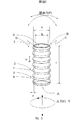
第1図は、本発明のアクチュエータ素子の一実施態様例についての概略斜視図である。
第2図は、第1図のアクチュエータ素子についての概略縦断面図である。
第3図は、本発明のアクチュエータ素子の一実施態様例についての概略斜視図である。FIG. 1 is a schematic perspective view of an embodiment of an actuator element according to the present invention.
FIG. 2 is a schematic longitudinal sectional view of the actuator element of FIG.
FIG. 3 is a schematic perspective view of an embodiment of the actuator element of the present invention.
以下、本発明について図を参照して説明するが、本発明は図に示された実施形態に限定されるものではない。
(アクチュエータ素子)
図1は、アクチュエータ素子の一実施態様例についての概略斜視図である。アクチュエータ素子1は、アクチュエータ素子が屈曲する方向に面する表面に凹凸を備え、前記凹凸が屈曲を容易にするための波形形状を形成するアクチュエータ素子である。アクチュエータ素子1は、管状であり、凸部2及び凹部3を備え、端部Aと端部Bの両方に開口部4を備えている。凸部2及び凹部3を具備する前記アクチュエータ素子の外側面は、略円筒状を形成していることから、4方向である屈曲方向に面することができる。
図1中のアクチュエータ素子1は、アクチュエータ素子の外側面に凹凸が形成されている。前記外側面において、前記凹凸が周方向Xに沿ってアクチュエータ素子の周囲を一巡する連続した凹凸が形成されている。前記アクチュエータ素子は、全体として蛇腹状に形成され、屈曲運動の幅方向に直行する軸Yの方向に対してアクチュエータ素子全体に波形形状が形成されている。
本発明のアクチュエータ素子は、アクチュエータ素子が屈曲する方向に面する表面に凹凸を備え、前記凹凸が屈曲を容易にするための波形形状を形成していれば、特に限定されるものではない。前記波形形状は、屈曲運動の先端となる端部付近(例えば図1のA付近)またはその反対側の端部付近(例えば図1のB付近)の一部分に形成されてもよく、屈曲運動の幅方向に直行する軸Yの方向に対してアクチュエータ素子の略全体に形成されても良い。また、アクチュエータ素子の屈曲が、例えば振幅のような、特定の方向にのみ屈曲運動する場合には、当該屈曲運動の方向に面する表面にのみ前記波形形状を形成することが、製造を容易にするために好ましい。本発明のアクチュエータ素子をカテーテル等のアクチュエータとして用いる場合など、先端部分が方向に制限されることなく大きな屈曲をすることが要求される用途に用いる場合には、本発明のアクチュエータ素子の波形形状は、周方向に沿ってアクチュエータ素子の周囲を一巡する連続した凹凸により形成されることが好ましい。前記表面は、略平面であっても良く、図1の様に曲面であっても良い。
本発明のアクチュエータ素子において、波形形状に形成されている部分がアクチュエータ素子の一部分である場合には、アクチュエータ素子の両方の端部のうち少なくともどちらか一の端部付近において波形形状に形成された部分が備えられていることが好ましい。アクチュエータ素子の両方の端部のうちのどちらか一の端部付近において波形形状に形成された部分が備えられ、前記波形形状に形成された端部が支持体等に固定された場合には、波形形状の部分が比較的短くても、他の端部は大きく変位することができるからである。特に前記アクチュエータ素子がカテーテルの先端に用いられる場合には、カテーテルの誘導を容易に行うことができるようにするために、カテーテルの最先端部分の対応する端部が蛇腹状に形成されていることが好ましい。
図1に示すように、凹凸により波形形状が形成されたアクチュエータ素子は、アクチュエータ素子である管状体に交互に凸部と凹部とが形成されて、蛇腹状を形成している。前記アクチュエータ素子は、屈曲する方向に面する表面に凹凸を備え、前記凹凸が屈曲を容易にするための波形形状を形成するアクチュエータ素子の一態様でもある。
図2は、図1に示したアクチュエータ素子1の概略縦断面図である。アクチュエータ素子1には電極層5と固体電解質層6とを備えている。本発明の蛇腹状に形成された管状のアクチュエータ素子は、湾曲若しくは変形が可能なアクチュエータ素子であって、全体または部分的に蛇腹状に形成されたアクチュエータ素子であれば、構成が特に限定されるものではないが、図2に示すように、湾曲を可能とするために電極層と固体電解質層とを備えていることが好ましい。本発明のアクチュエータ素子は、蛇腹状に形成されているので、蛇腹状に形成されて部分についても電極層と固体電解質層とを備えている。前記電極層に通電することにより前記固体電解質層が屈曲若しくは変位を生じるのである。前記電極層は、アクチュエータ素子1が屈曲可能な様に形成されていれば良い。特に、屈曲可能な素子を容易に形成することができることから、前記アクチュエータ素子の電極層は、軸方向に形成された絶縁溝を備えることにより互いに絶縁された2以上の電極層であることが好ましい。前記電極層は、軸方向に形成された絶縁溝により電極層が円周方向に互いに絶縁された状態で分割されることが、軸Yに垂直方向に自由に屈曲できるために好ましい。分割された一の電極層が軸方向に形成された前記絶縁溝により他の電極層と互いに絶縁されることにより、アクチュエータ素子1は、軸Yに垂直方向に自由に屈曲できる。
図3は、本発明のアクチュエータ素子であって、螺旋状に形成されているアクチュエータ素子1’を示す概略斜視図である。本発明は、アクチュエータ素子が屈曲する方向に面する表面に凹凸を備え、前記凹凸が屈曲を容易にするための波形形状を形成するアクチュエータ素子の一態様であり、表面の凹凸が螺旋状に形成されたアクチュエータ素子でもある。螺旋状に形成された管状のアクチュエータ素子1’は、図1の蛇腹状に形成された管状のアクチュエータ素子1を同様に、凸部2’及び凹部3’を備え、端部A’と端部B’の両方に開口部4’を備えている。
図3のアクチュエータ素子1’は、アクチュエータ素子の略全体が螺旋状に形成されている。本発明の螺旋状に形成されたアクチュエータ素子は、蛇腹状に形成されたアクチュエータ素子と同様に、大きな屈曲をすることができるのでアクチュエータ素子1’のように屈曲運動の幅方向に直行する軸方向の略全体に形成されることが好ましい。また、本発明のアクチュエータ素子は、螺旋状に形成されている部分がアクチュエータ素子の一部分である場合には、蛇腹状に形成されたアクチュエータ素子と同様に、アクチュエータ素子の両方の端部のうち少なくともどちらか一の端部付近に螺旋状に形成された部分が備えられていることが好ましい。アクチュエータ素子1’は、図1のアクチュエータ素子1と同様に、外側面に電極層を備える。また、アクチュエータ素子1’は、図1のアクチュエータ素子1と同様の理由により、絶縁溝を備えることが好ましい。
本発明のアクチュエータ素子は、図1〜3のアクチュエータ素子1及びアクチュエータ素子1’では中空管状の形状をしているが、中空管状の形状に限定されるものではない。本発明のアクチュエータ素子は、屈曲する方向に面する表面に凹凸を備え、前記凹凸が屈曲を容易にするための波形形状を形成するアクチュエータ素子であれば、形状について特に限定されず、例えば、球状、立方、柱状、錐状、棒状、管状、筒状等の立体形状が蛇腹状に形成されたものであってもよい。特に、本発明のアクチュエータ素子は、長手方向を有する立体形状物であることが、屈曲運動を容易にすることができ、より大きな機械的エネルギーを得ることができるので好ましい。前記長手方向を有する立体形状物としては、柱状体、錐状体、棒状体、管状体及び筒状体を例示することができ、中空であってもよい。本発明のアクチュエータ素子が、中空の管状または筒状である場合には、屈曲する方向に面する表面に備えられた凹凸が形成する波形形状が外周面に形成されていても内周面に形成されていても良いが、より大きな屈曲をすることができるので、前記波形形状が外周面及び内周面の両方に形成されていることがより好ましく、さらに波形形状が蛇腹状若しくは螺旋状に形成されていることが特に好ましい。
本発明のアクチュエータ素子について、アクチュエータ素子が屈曲する方向に面する表面に凹凸を備え、前記凹凸が屈曲を容易にするための波形形状を形成するアクチュエータ素子の形成方法は、特に限定されるものではなく、公知の形成方法で形成することができる。例えば、前記波形形状が形成された管状のアクチュエータ素子は、金型等で蛇腹状の管状に形成されたイオン交換樹脂成形品に、公知の方法によりメッキを施して金属の電極層を形成することにより得ることができるが、以下の方法で得ることが好ましい。
即ち、アクチュエータ素子の製造方法であって、イオン交換樹脂成形品にワイヤーを捲きつけることのより表面に螺旋状の凹凸を設ける工程、この凹凸を設けたイオン交換樹成形品に金属錯体を吸着させる工程、前記イオン交換樹脂成形品に吸着された金属錯体に還元剤を作用させることにより前記イオン交換樹脂の表面に金属を析出させる工程、及び金属が析出したイオン交換樹脂を洗浄液で洗浄する工程、
を含むアクチュエータ素子の製造方法により、前記アクチュエータ素子を容易な作業により形成することができる。
また、本発明である螺旋状に形成された管状アクチュエータ素子は、蛇腹状に形成された管状のアクチュエータ素子と同様に、全体または一部分に螺旋状に形成された部分を備えているが、この螺旋状に形成さている部分の形成方法、特に限定されるものではなく、公知の形成方法で形成することができる。例えば、蛇腹状に形成された管状のアクチュエータ素子は、固体電解質の管状体として、蛇腹状の管状のイオン交換樹脂成形品に公知の方法によりメッキを施して金属の電極層を形成することにより簡単に得ることができるが、以下の方法で得ることが好ましい。
蛇腹状に形成されたアクチュエータ素子の製造方法としては、管状体であるイオン交換樹脂成形品に所定の直径のワイヤーを捲きつけて管状体の表面に蛇腹状の凹凸を設ける工程、この凹凸を設けた管状のイオン交換樹成形品に金属錯体を吸着させる工程、前記イオン交換樹脂成形品に吸着された金属錯体に還元剤を作用させることにより前記イオン交換樹脂の表面に金属を析出させる工程、及び、金属が析出したイオン交換樹脂を洗浄液で洗浄する工程を含むアクチュエータ素子の製造方法を用いることにより、本発明である蛇腹状に形成されたアクチュエータ素子を簡便な方法で形成することができる。なお、前記ワイヤーの直径は、所望の凹凸を管状のアクチュエータ素子に与えるために、適宜選択されれば良い。
また、螺旋状に形成された管状アクチュエータ素子を得る方法としては、アクチュエータ素子の製造方法であって、イオン交換樹脂成形品にワイヤーを捲きつけることのより表面に螺旋状の凹凸を設ける工程、この凹凸を設けたイオン交換樹成形品に金属錯体を吸着させる工程、前記イオン交換樹脂成形品に吸着された金属錯体に還元剤を作用させることにより前記イオン交換樹脂の表面に金属を析出させる工程、及び金属が析出したイオン交換樹脂を洗浄液で洗浄する工程を含むアクチュエータ素子の製造方法である。
本発明である蛇腹状に形成された管状のアクチュエータ素子及び螺旋状に形成された管状アクチュエータ素子は、凸部及び凹部を備えているが、凸部の頂部と凹部の底部が、角を形成していても曲面を形成していても良いが、凸部の頂部と凹部の底部とにも容易にメッキを施すこができ、アクチュエータ素子の屈曲または変位の際に前記頂部若しくは前記底部とにおいての電極層の断線が生じにくいので、凸部の頂部と凹部の底部とが曲面を形成していることが好ましい。また、前記アクチュエータ素子における凹凹間ピッチ(図1または図3におけるdまたはd’)は、特に限定されるものではないが、管状体の直径0.8mmに対して0.1〜0.3mmであれば凸部の頂部と凹部の底部とにも容易にメッキを施すこができるので好ましい。また、凸部の頂部と凹部の底部との差である凹凸の深さ(図1または3におけるeまたはe’)は、特に限定されるものではないが、アクチュエータ素子の厚さ(図1または図3におけるa−b、またはa’−b’)に対して10%〜200%であることが好ましい。
(固定電解質層及び電極層)
また、本願における発明であるアクチュエータ素子が屈曲する方向に面する表面に凹凸を備え、前記凹凸が屈曲を容易にするための波形形状を形成するアクチュエータ素子は、図2に示すように、屈曲可能な構造を容易に形成することができることから、固定電解質層と電極層とを備えていることが好ましい。前記固体電極層としては、特に限定されるものではなく、イオン交換樹脂を用いることが好ましい。特に、前記固体電解質層は、耐久性のためにフッ素系イオン交換樹脂を用いることがより好ましい。前記電極層についても特に限定されるものではなく、通電性を有する層であれば特に限定されるものではないが、固体電解質にメッキを施すことにより簡単に電極層を形成することができることから、金属電極層であることが好ましく、通電性の良い銅(Cu)、金(Au)、銀(Ag)、白金(Pt)などの電導性金属を主として含む電極層であることがより好ましい。
(用途)
前記アクチュエータ素子は、多数の部品を必要としないために、構造が簡単であり、屈曲が大きく、しかも軽量であることから、種々の装置の駆動部または押圧部に好適に用いることができる。つまり、アクチュエータ素子が屈曲する方向に面する表面に凹凸を備え、前記凹凸が屈曲を容易にするための波形形状を形成するアクチュエータ素子は、位置決め装置、姿勢制御装置、昇降装置、搬送装置、移動装置、調節装置、調整装置、誘導装置、及び関節装置として好適である。また、前記アクチュエータ素子は押圧装置として好適である。
前記アクチュエータ素子は、OA機器、アンテナ、ベッドや椅子等の人を乗せる装置、医療機器、エンジン、光学機器、固定具、サイドトリマ、車両、昇降器械、食品加工装置、清掃装置、測定機器、検査機器、制御機器、工作機械、加工機械、電子機器、電子顕微鏡、電気かみそり、電動歯ブラシ、マニピュレータ、マスト、遊戯装置、アミューズメント機器、乗車用シミュレーション装置、車両乗員の押さえ装置及び航空機用付属装備展張装置において、円弧部からなるトラック型の軌道を移動するための駆動力を発生する駆動部、または曲線的な動作をする押圧部として好適に用いることができる。前記アクチュエータは、例えば、OA機器や測定機器等の上記機器等を含む機械全般に用いられる弁、ブレーキ及びロック装置において、円弧部からなるトラック型の軌道を移動するための駆動力を発生する駆動部、または曲線的な動作をする押圧部として用いることができる。また、前記アクチュエータ素子は、前記の装置、機器、器械等以外においても、機械機器類全般において、位置決め装置の駆動部、姿勢制御装置の駆動部、昇降装置の駆動部、搬送装置の駆動部、移動装置の駆動部、量や方向等の調節装置の駆動部、軸等の調整装置の駆動部、誘導装置の駆動部、及び押圧装置の押圧部として好適に用いることができる。また、前記アクチュエータ素子は、関節装置における駆動部として、関節部または関節に回転運動を与える駆動部に好適に用いることができる。Hereinafter, the present invention will be described with reference to the drawings, but the present invention is not limited to the embodiments shown in the drawings.
(Actuator element)
FIG. 1 is a schematic perspective view of an embodiment of an actuator element. The
The
The actuator element of the present invention is not particularly limited as long as it has irregularities on the surface facing the direction in which the actuator element bends, and the irregularities form a corrugated shape for facilitating the bending. The corrugated shape may be formed in the vicinity of an end portion (for example, near A in FIG. 1) or a portion near the opposite end portion (for example, in the vicinity of B in FIG. 1) of the bending motion. It may be formed on substantially the entire actuator element with respect to the direction of the axis Y orthogonal to the width direction. Further, when the bending of the actuator element bends only in a specific direction such as amplitude, for example, it is easy to manufacture by forming the corrugated shape only on the surface facing the direction of the bending movement. This is preferable. When the actuator element of the present invention is used as an actuator such as a catheter or the like and used for an application that requires a large bend without restricting the tip portion in the direction, the waveform shape of the actuator element of the present invention is It is preferably formed by continuous unevenness that goes around the circumference of the actuator element along the circumferential direction. The surface may be a substantially flat surface or a curved surface as shown in FIG.
In the actuator element of the present invention, when the portion formed in the waveform shape is a part of the actuator element, it is formed in the waveform shape in the vicinity of at least one of both ends of the actuator element. It is preferred that a portion is provided. When a portion formed in a waveform shape is provided near either one of both ends of the actuator element, and the end portion formed in the waveform shape is fixed to a support or the like, This is because even if the corrugated portion is relatively short, the other end portion can be greatly displaced. In particular, when the actuator element is used at the distal end of the catheter, the corresponding end of the most distal portion of the catheter is formed in a bellows shape so that the catheter can be guided easily. Is preferred.
As shown in FIG. 1, an actuator element having a corrugated shape formed by irregularities has a bellows shape in which convex portions and concave portions are alternately formed in a tubular body that is an actuator element. The actuator element is also an aspect of an actuator element that has unevenness on a surface facing in a bending direction, and the unevenness forms a waveform shape for facilitating bending.
FIG. 2 is a schematic longitudinal sectional view of the
FIG. 3 is a schematic perspective view showing the
In the
The actuator element of the present invention has a hollow tubular shape in the
With respect to the actuator element of the present invention, the method of forming the actuator element is not particularly limited, wherein the actuator element is provided with irregularities on the surface facing the direction in which the actuator element bends, and the irregularities form a corrugated shape for facilitating the bending. However, it can be formed by a known forming method. For example, the tubular actuator element formed with the corrugated shape is formed by plating the ion-exchange resin molded product formed in a bellows-like tubular shape with a mold or the like by a known method to form a metal electrode layer. However, it is preferably obtained by the following method.
That is, a method for manufacturing an actuator element, in which a wire is attached to an ion exchange resin molded product to form a spiral concavo-convex surface, and a metal complex is adsorbed to the ion exchange tree molded product provided with the concavo-convex A step, a step of precipitating a metal on the surface of the ion exchange resin by allowing a reducing agent to act on the metal complex adsorbed on the ion exchange resin molded article, and a step of washing the ion exchange resin on which the metal is precipitated with a cleaning liquid,
The actuator element can be formed by an easy operation by the method for manufacturing an actuator element including:
Further, the tubular actuator element formed in a spiral shape according to the present invention includes a part formed in a spiral shape in whole or in part, like the tubular actuator element formed in a bellows shape. The formation method of the part currently formed in the shape is not specifically limited, It can form with a well-known formation method. For example, a bellows-shaped tubular actuator element can be easily obtained by forming a metal electrode layer by plating a bellows-shaped tubular ion-exchange resin molded product by a known method as a solid electrolyte tubular body. However, it is preferably obtained by the following method.
As a manufacturing method of the actuator element formed in a bellows shape, a step of forming a bellows-like unevenness on the surface of the tubular body by winding a wire having a predetermined diameter on an ion exchange resin molded product that is a tubular body, and providing this unevenness A step of adsorbing a metal complex on a tubular ion-exchange resin molded article, a step of depositing a metal on the surface of the ion-exchange resin by causing a reducing agent to act on the metal complex adsorbed on the ion-exchange resin molded article, and By using the method for manufacturing an actuator element including the step of cleaning the ion exchange resin on which the metal is deposited with a cleaning liquid, the actuator element formed in the bellows shape according to the present invention can be formed by a simple method. The diameter of the wire may be appropriately selected in order to give a desired unevenness to the tubular actuator element.
Moreover, as a method of obtaining a tubular actuator element formed in a spiral shape, a method for manufacturing an actuator element, in which a spiral unevenness is provided on the surface by wire-bonding an ion exchange resin molded product, A step of adsorbing a metal complex on an ion-exchange resin molded article provided with irregularities, a step of depositing a metal on the surface of the ion-exchange resin by acting a reducing agent on the metal complex adsorbed on the ion-exchange resin molded article, And a method of manufacturing an actuator element including a step of cleaning an ion exchange resin on which a metal is deposited with a cleaning liquid.
The tubular actuator element formed in a bellows shape and the tubular actuator element formed in a spiral shape according to the present invention have a convex part and a concave part, but the top part of the convex part and the bottom part of the concave part form a corner. Or the curved surface may be formed, but the top of the convex portion and the bottom of the concave portion can be easily plated, and when the actuator element is bent or displaced, the top portion or the bottom portion Since disconnection of the electrode layer is unlikely to occur, it is preferable that the top part of the convex part and the bottom part of the concave part form a curved surface. The pitch between the concaves and convexes in the actuator element (d or d ′ in FIG. 1 or 3) is not particularly limited, but is 0.1 to 0.3 mm with respect to the diameter of the tubular body of 0.8 mm. If so, it is preferable because plating can be easily applied to the top of the projection and the bottom of the recess. Further, the depth of the unevenness (e or e ′ in FIG. 1 or 3), which is the difference between the top of the convex portion and the bottom of the concave portion, is not particularly limited, but the thickness of the actuator element (FIG. 1 or It is preferable that it is 10%-200% with respect to ab in FIG. 3, or a'-b ').
(Fixed electrolyte layer and electrode layer)
In addition, the actuator element according to the invention of the present application is provided with irregularities on the surface facing the direction of bending, and the actuator elements forming the corrugated shape for facilitating the bending can be bent as shown in FIG. Since a simple structure can be easily formed, it is preferable to include a fixed electrolyte layer and an electrode layer. The solid electrode layer is not particularly limited, and an ion exchange resin is preferably used. In particular, the solid electrolyte layer is more preferably made of a fluorine ion exchange resin for durability. The electrode layer is not particularly limited, and is not particularly limited as long as it is a conductive layer, but it is possible to easily form an electrode layer by plating a solid electrolyte. A metal electrode layer is preferable, and an electrode layer mainly including a conductive metal such as copper (Cu), gold (Au), silver (Ag), or platinum (Pt) having good electrical conductivity is more preferable.
(Use)
Since the actuator element does not require a large number of parts, the structure is simple, the bending is large, and the weight is light. Therefore, the actuator element can be suitably used for a driving unit or a pressing unit of various devices. That is, an actuator element that has irregularities on the surface facing the direction in which the actuator element bends, and the irregularities form a waveform shape for facilitating the bending, is a positioning device, a posture control device, a lifting device, a conveying device, a moving device It is suitable as a device, an adjustment device, an adjustment device, a guidance device, and a joint device. The actuator element is suitable as a pressing device.
The actuator element is an OA device, an antenna, a device on which a person such as a bed or a chair is placed, a medical device, an engine, an optical device, a fixture, a side trimmer, a vehicle, a lifting device, a food processing device, a cleaning device, a measuring device, an inspection. Equipment, control equipment, machine tools, processing machines, electronic equipment, electron microscopes, electric razors, electric toothbrushes, manipulators, masts, amusement equipment, amusement equipment, riding simulation equipment, vehicle occupant pressers, and aircraft accessory
以下、本発明の実施例及び比較例を記載するが、これらに特に限定されるものではない。なお、イオン交換樹脂成形品についてのa、b、c、及びdは、図1及び図3に示すように、蛇腹状又は螺旋状の管状体についての、開口部外形、開口部内径、長さ、凹凹間ピッチを示す。
(イオン交換樹脂成形品A及びBの製造例)
イオン交換膜(パーフルオロカルボン酸樹脂、イオン交換容量1.80meq/g、商品名「フレミオン」、旭硝子社製)を用いて公知の射出成形方法によりa=0.8mm、b=0.5mm、c=20mm、d=1.5mmの蛇腹状の管状体であるイオン交換樹脂成形品Aを得た。イオン交換膜(パーフルオロカルボン酸樹脂、イオン交換容量1.80meq/g、商品名「フレミオン」、旭硝子社製)を用いて公知の射出成形方法により、a=0.6mm、b=0.4mm、c=20mm、d=1.5mmの蛇腹状の管状体であるイオン交換樹脂成形品Bを得た。
(イオン交換樹脂成形品Cの製造例)
イオン交換膜(パーフルオロカルボン酸樹脂、商品名「フレミオン」、旭硝子社製)を用いて公知の射出成形方法により円筒状の管状体を成形し、その管状体にワイヤーを螺旋状に捲きつけることにより表面に螺旋状の凹凸を設けて、a=0.6mm、b=0.4mm、c=20mm、d=1.5mmのである螺旋状に形成されたイオン交換樹脂成形品を得た。
(イオン交換樹脂成形品Dの製造例)
イオン交換膜(パーフルオロカルボン酸樹脂、商品名「フレミオン」、旭硝子社製)を用いて公知の射出成形方法により円筒状の管状体を成形し、a=0.6mm、b=0.4mm、c=20mmのである円筒状のイオン交換樹脂成形品を得た。Hereinafter, although the Example and comparative example of this invention are described, it does not specifically limit to these. In addition, a, b, c, and d for the ion exchange resin molded product are the outer shape of the opening, the inner diameter of the opening, and the length of the bellows-like or spiral tubular body, as shown in FIGS. , Indicates the pitch between the recesses.
(Production example of ion exchange resin molded products A and B)
Using an ion exchange membrane (perfluorocarboxylic acid resin, ion exchange capacity 1.80 meq / g, trade name “Flemion”, manufactured by Asahi Glass Co., Ltd.), a = 0.8 mm, b = 0.5 mm, An ion exchange resin molded product A which is a bellows-like tubular body with c = 20 mm and d = 1.5 mm was obtained. Using an ion exchange membrane (perfluorocarboxylic acid resin, ion exchange capacity 1.80 meq / g, trade name “Flemion”, manufactured by Asahi Glass Co., Ltd.), a = 0.6 mm, b = 0.4 mm , C = 20 mm, d = 1.5 mm An ion-exchange resin molded product B which is a bellows-like tubular body was obtained.
(Production example of ion exchange resin molded product C)
A cylindrical tubular body is formed by a known injection molding method using an ion exchange membrane (perfluorocarboxylic acid resin, trade name “Flemion”, manufactured by Asahi Glass Co., Ltd.), and a wire is spirally wound around the tubular body. Thus, an ion exchange resin molded article formed in a spiral shape with a = 0.6 mm, b = 0.4 mm, c = 20 mm, and d = 1.5 mm was provided on the surface.
(Production example of ion-exchange resin molded product D)
A cylindrical tubular body is formed by a known injection molding method using an ion exchange membrane (perfluorocarboxylic acid resin, trade name “Flemion”, manufactured by Asahi Glass Co., Ltd.), and a = 0.6 mm, b = 0.4 mm, A cylindrical ion exchange resin molded product having c = 20 mm was obtained.
イオン交換樹脂成形品Aに対して#800のアルミナ粒子で表面粗化を行った後、下記(1)〜(3)の工程を7サイクル繰り返して実施し、イオン交換樹脂成形品表面へ金電極を形成させた。(1)吸着工程:フェナントリン金塩化物水溶液に24時間浸漬し、成形品内にフェナントリン金錯体を吸着させ、(2)析出工程:亜硫酸ナトリウムを含む水溶液中で、吸着したフェナントリン金錯体を還元して、イオン交換樹脂成形品表面に金電極を形成させた。このとき、水溶液の温度を60〜80℃とし、亜硫酸ナトリウムを徐々に添加しながら、6時間フェナントリン金錯体の還元を行った。次いで、(3)洗浄工程:表面に金電極が形成したイオン交換樹脂成形品を取り出し、70℃の水で1時間洗浄し、金電極が形成されたイオン樹脂成形品を得た。この金電極が形成されたイオン樹脂成形品を公知のエキシマレーザー加工装置を用いて長手方向に直線的にレーザー照射することにより合計4本の絶縁溝を形成し、2組の電極対を形成した。この2組の電極対が形成されたイオン交換樹脂成形品を0.5M(C4H9)4NCl水溶液に24時間浸漬することにより実施例1の蛇腹状に形成されたアクチュエータ素子を得た。
(実施例2及び3)
イオン交換樹脂成形品Aの替わりに、イオン交換樹脂成形品Bまたはイオン交換樹脂成形品Cを用いたこと以外は、実施例1と同様の方法によりアクチュエータ素子を得て、それぞれ実施例2または実施例3の蛇腹状または螺旋状に形成されたアクチュエータ素子とした。
(比較例)
イオン交換樹脂成形品Aの替わりに、イオン交換樹脂成形品Dを用いたこと以外は、実施例1と同様の方法によりアクチュエータ素子を得て、比較例1の凹凸のない円筒状のアクチュエータ素子とした。
(評価)
実施例1〜3及び比較例の各アクチュエータ素子について、それぞれの電極にそれぞれリード取り付けて電源と接続した。各アクチュエータ素子について、アクチュエータ素子の一端を支持体で固定して、先端(他端)が鉛直下向きとなるように水中に設置し、鉛直下向き0.1Hzの矩形波で2.0V、2.5V、及び3.0Vの電圧をそれぞれ30秒間印加し、アクチュエータ素子の支持体による固定部分からアクチュエータ素子先端部分までについての曲がりを円に近似して極率半径を測定し、下記の評価基準で評価した。結果は表1に示す。
(評価基準)
○:30秒間の印加による屈曲で、極率半径が6mm以下で良好である。
△:30秒間の印加による屈曲で、極率半径が7mm以上、8mm以下であり、カテーテル等のアクチュエータ素子として実用可能である。
×:30秒間の印加による屈曲で、極率半径が9mm以上であり、カテーテル等の大きな屈曲が要求されるアクチュエータ素子には不向きである。

実施例1及び2のアクチュエータ素子は、蛇腹状に成形された管状のアクチュエータ素子であり、表面に凹凸が形成されていない従来のアクチュエータ素子である比較例のアクチュエータ素子と比べて、30秒という短時間に従来より大きな屈曲が得られ、良好であった。特に、印加電圧3.0Vにおいては、極率半径が約2倍小さく、従来にない大きな屈曲が得られ、優れた屈曲を示した。
実施例3のアクチュエータ素子は、螺旋状に成形された管状のアクチュエータ素子であり、側面に対して凹凸が形成されていない従来のアクチュエータ素子である比較例のアクチュエータ素子と比べて、30秒という短時間に従来より大きな屈曲が得られ、良好であった。特に、印加電圧3.0Vにおいては、極率半径が約2倍小さく、従来にない大きな屈曲が得られ、優れた屈曲を示した。
即ち、本発明のアクチュエータ素子であるアクチュエータ素子が屈曲する方向に面する表面に凹凸を備え、前記凹凸が屈曲を容易にするための波形形状を形成するアクチュエータ素子は、実施例1〜3に示すように優れた屈曲を示した。After surface roughening with # 800 alumina particles on the ion exchange resin molded product A, the following steps (1) to (3) are repeated 7 cycles, and a gold electrode is applied to the surface of the ion exchange resin molded product. Formed. (1) Adsorption step: Immerse in an aqueous solution of phenanthrin gold chloride for 24 hours to adsorb the phenanthrin gold complex in the molded product. (2) Precipitation step: Reduce the adsorbed phenanthrin gold complex in an aqueous solution containing sodium sulfite. Thus, a gold electrode was formed on the surface of the ion exchange resin molded product. At this time, the temperature of the aqueous solution was set to 60 to 80 ° C., and the phenanthrine gold complex was reduced for 6 hours while gradually adding sodium sulfite. Next, (3) washing step: the ion exchange resin molded product with the gold electrode formed on the surface was taken out and washed with 70 ° C. water for 1 hour to obtain an ion resin molded product with the gold electrode formed. A total of four insulating grooves were formed by linearly irradiating the ion resin molded article on which the gold electrode was formed with a known excimer laser processing apparatus in the longitudinal direction, thereby forming two pairs of electrodes. . The ion exchange resin molded article formed with the two pairs of electrodes was immersed in a 0.5 M (C 4 H 9 ) 4 NCl aqueous solution for 24 hours to obtain the actuator element formed in the bellows shape of Example 1. .
(Examples 2 and 3)
An actuator element was obtained in the same manner as in Example 1 except that the ion exchange resin molded product B or the ion exchange resin molded product C was used instead of the ion exchange resin molded product A. The actuator element formed in the bellows shape or the spiral shape in Example 3 was used.
(Comparative example)
Except for using the ion exchange resin molded product D instead of the ion exchange resin molded product A, an actuator element was obtained by the same method as in Example 1, and the cylindrical actuator element having no unevenness of Comparative Example 1 was obtained. did.
(Evaluation)
About each actuator element of Examples 1-3 and a comparative example, each lead was attached to each electrode and it connected with the power supply. For each actuator element, one end of the actuator element is fixed with a support, and the tip (the other end) is placed in water so that the tip is vertically downward. , And a voltage of 3.0 V were applied for 30 seconds, respectively, and the radius of curvature was measured by approximating the bend from the fixed part of the actuator element support to the tip of the actuator element to a circle, and evaluated according to the following evaluation criteria did. The results are shown in Table 1.
(Evaluation criteria)
○: Bending by application for 30 seconds, good with a radius of curvature of 6 mm or less.
(Triangle | delta): It is the bending | flexion by the application for 30 second, and a polar radius is 7 mm or more and 8 mm or less, and it is practical as actuator elements, such as a catheter.
X: Bending by application for 30 seconds, the radius of curvature is 9 mm or more, and is not suitable for an actuator element that requires a large bending such as a catheter.
The actuator elements of Examples 1 and 2 are tubular actuator elements formed in a bellows shape, which is 30 seconds shorter than the actuator element of the comparative example which is a conventional actuator element having no irregularities on the surface. Bending that was larger than before was obtained, and it was good. In particular, at an applied voltage of 3.0 V, the polarity radius was about twice as small, and a large bending that was not possible in the past was obtained, indicating an excellent bending.
The actuator element of Example 3 is a tubular actuator element formed in a spiral shape, which is 30 seconds shorter than the actuator element of the comparative example which is a conventional actuator element in which unevenness is not formed on the side surface. Bending that was larger than before was obtained, and it was good. In particular, at an applied voltage of 3.0 V, the polarity radius was about twice as small, and a large bending that was not possible in the past was obtained, indicating an excellent bending.
That is, the actuator element which is provided with unevenness on the surface facing the direction in which the actuator element which is the actuator element of the present invention is bent, and the unevenness forms a wave shape for facilitating bending, is shown in Examples 1 to 3. Showed excellent bending.
本発明のアクチュエータ素子は、アクチュエータの駆動部に用いることができ、従来のアクチュエータ素子に比べて同一電圧での変位量が大きいので、電気エネルギーを機械的エネルギーに変換する効率が高く、同一電圧でよりアクチュエータとしての大きな駆動力を得ることができる。また、前記アクチュエータ素子は、変位速度も速いために、アクチュエータ素子の金属電極に電圧をかけてから変形が終了するまでの時間が短いので、変形の指示に対する応答性が速く、アクチュエータとしての操作性も良好となる。
本発明のアクチュエータ素子が高分子アクチュエータ素子である場合には、マイクロサージェリー技術におけるピンセット、ハサミ、鉗子、スネア、レーザメス、スパチュラ、クリップなどの医療器具、検査や補修等を行う各種センサー若しくは補修用工具など、健康器具、湿度計、湿度計コントロール装置、ソフトマニュピュレーター、水中バルブ、ソフト運搬装置などの工業用機器、金魚などの水中モービル、または動く釣り餌や推進ヒレなどのホビー用品などの水中で用いられる物品についても好適に使用することができる。
また、前記アクチュエータ素子は、多数の部品を必要としないために、構造が簡単であり、屈曲が大きく、しかも軽量であることから、位置決め装置、姿勢制御装置、昇降装置、搬送装置、移動装置、調節装置、調整装置、誘導装置、関節装置、及び押圧装置として好適である。The actuator element of the present invention can be used in the actuator drive unit and has a large displacement amount at the same voltage compared to the conventional actuator element. Therefore, the efficiency of converting electrical energy into mechanical energy is high, and the same voltage is used. A greater driving force as an actuator can be obtained. In addition, since the actuator element has a high displacement speed, the time from when voltage is applied to the metal electrode of the actuator element to the end of deformation is short, so the response to the deformation instruction is fast and the operability as an actuator is high. Will also be good.
When the actuator element of the present invention is a polymer actuator element, medical instruments such as tweezers, scissors, forceps, snare, laser knife, spatula and clip in microsurgery technology, various sensors for inspection and repair, or for repair Tools, health equipment, hygrometers, hygrometer control devices, soft manipulators, underwater valves, soft transporters and other industrial equipment, underwater mobiles such as goldfish, or hobby items such as moving fishing baits and propeller fins Articles used in water can also be suitably used.
In addition, since the actuator element does not require a large number of parts, the structure is simple, the bending is large, and the weight is low, so that the positioning device, the attitude control device, the lifting device, the conveying device, the moving device, It is suitable as an adjusting device, an adjusting device, a guiding device, a joint device, and a pressing device.
Claims (7)
アクチュエータ素子が屈曲する方向に面する表面に凹凸を備え、
前記凹凸が屈曲を容易にするための波形形状を形成するアクチュエータ素子。A solid metal layer is provided with a pair of metal layers, and the pair of metal layers is formed on the outer surface of the actuator element by insulating grooves along the longitudinal direction,
The surface facing the direction in which the actuator element bends is provided with irregularities,
An actuator element in which the unevenness forms a wave shape for facilitating bending.
イオン交換樹脂成形品にワイヤーを捲きつけることにより表面に螺旋状の凹凸を設ける工程、
この凹凸を設けたイオン交換樹成形品に金属錯体を吸着させる工程、
前記イオン交換樹脂成形品に吸着された金属錯体に還元剤を作用させることにより前記イオン交換樹脂の表面に金属を析出させる工程、及び
金属が析出したイオン交換樹脂を洗浄液で洗浄する工程を含むアクチュエータ素子の製造方法。It is a manufacturing method of the actuator element according to claim 4,
Step of providing a spiral irregularities more surface to give Maki a wire to an ion exchange resin moldings,
A step of adsorbing a metal complex to the ion-exchanged tree molded article provided with the unevenness,
An actuator comprising a step of precipitating a metal on the surface of the ion exchange resin by causing a reducing agent to act on the metal complex adsorbed on the ion exchange resin molded article, and a step of washing the ion exchange resin on which the metal is deposited with a cleaning liquid Device manufacturing method.
Applications Claiming Priority (3)
| Application Number | Priority Date | Filing Date | Title |
|---|---|---|---|
| JP2002274929 | 2002-09-20 | ||
| JP2002274929 | 2002-09-20 | ||
| PCT/JP2003/011959 WO2004026758A1 (en) | 2002-09-20 | 2003-09-19 | Driver and method of producing the same |
Publications (2)
| Publication Number | Publication Date |
|---|---|
| JPWO2004026758A1 JPWO2004026758A1 (en) | 2006-01-12 |
| JP4575774B2 true JP4575774B2 (en) | 2010-11-04 |
Family
ID=32025017
Family Applications (1)
| Application Number | Title | Priority Date | Filing Date |
|---|---|---|---|
| JP2004537991A Expired - Fee Related JP4575774B2 (en) | 2002-09-20 | 2003-09-19 | Driver and manufacturing method thereof |
Country Status (3)
| Country | Link |
|---|---|
| JP (1) | JP4575774B2 (en) |
| AU (1) | AU2003264504A1 (en) |
| WO (1) | WO2004026758A1 (en) |
Families Citing this family (4)
| Publication number | Priority date | Publication date | Assignee | Title |
|---|---|---|---|---|
| JP4661110B2 (en) * | 2004-07-07 | 2011-03-30 | ダイキン工業株式会社 | Polymer actuator |
| JP5281322B2 (en) * | 2007-06-21 | 2013-09-04 | パナソニック株式会社 | Electric telescopic mechanism and actuator |
| WO2013122047A1 (en) * | 2012-02-14 | 2013-08-22 | 国立大学法人信州大学 | Gel actuator and method for producing same |
| JP2016140407A (en) * | 2015-01-30 | 2016-08-08 | 国立研究開発法人産業技術総合研究所 | Catheter system |
Citations (10)
| Publication number | Priority date | Publication date | Assignee | Title |
|---|---|---|---|---|
| JPH0775356A (en) * | 1993-09-02 | 1995-03-17 | Olympus Optical Co Ltd | Mechanochemical actuator |
| JPH0779026A (en) * | 1993-06-30 | 1995-03-20 | Tokin Corp | Piezoelectric actuator and its manufacture |
| JPH07135345A (en) * | 1993-11-09 | 1995-05-23 | Casio Comput Co Ltd | Piezoelectric element |
| JPH08131545A (en) * | 1994-11-10 | 1996-05-28 | Terumo Corp | Internal insertion device having electrically conductive way, and manufacture thereof |
| JPH10258022A (en) * | 1997-01-20 | 1998-09-29 | Suzuki Motor Corp | Hybrid operation system |
| JPH1193827A (en) * | 1997-09-18 | 1999-04-06 | Toshiba Corp | Functional element and actuator |
| JP2961125B2 (en) * | 1998-02-20 | 1999-10-12 | 工業技術院長 | Method for manufacturing polymer actuator |
| JPH11280639A (en) * | 1998-03-30 | 1999-10-15 | Agency Of Ind Science & Technol | High polymer electrolyte ammonium derivative |
| JP2003181250A (en) * | 2001-12-18 | 2003-07-02 | Asahi Glass Engineering Co Ltd | Polymer osmosis membrane assembly |
| JP2004512885A (en) * | 2000-11-02 | 2004-04-30 | ダンフォス アクチーセルスカブ | Actuator and method of manufacturing the same |
Family Cites Families (6)
| Publication number | Priority date | Publication date | Assignee | Title |
|---|---|---|---|---|
| JPH06284750A (en) * | 1993-03-29 | 1994-10-07 | Nippondenso Co Ltd | Laminated electrostatic actuator |
| JPH08216876A (en) * | 1995-02-14 | 1996-08-27 | Nippondenso Co Ltd | In-pipe traveling device |
| US6013024A (en) * | 1997-01-20 | 2000-01-11 | Suzuki Motor Corporation | Hybrid operation system |
| ES2293710T3 (en) * | 1998-02-20 | 2008-03-16 | National Institute Of Advanced Industrial Science And Technology | POLYMERIC ACTUATORS AND PROCEDURES FOR PRODUCERS. |
| JP2000133854A (en) * | 1998-10-27 | 2000-05-12 | Matsushita Electric Works Ltd | Actuator |
| JP2003266392A (en) * | 2002-03-15 | 2003-09-24 | Rigaku Corp | Movement device using fluid responding to magnetic field |
-
2003
- 2003-09-19 WO PCT/JP2003/011959 patent/WO2004026758A1/en active Application Filing
- 2003-09-19 JP JP2004537991A patent/JP4575774B2/en not_active Expired - Fee Related
- 2003-09-19 AU AU2003264504A patent/AU2003264504A1/en not_active Abandoned
Patent Citations (10)
| Publication number | Priority date | Publication date | Assignee | Title |
|---|---|---|---|---|
| JPH0779026A (en) * | 1993-06-30 | 1995-03-20 | Tokin Corp | Piezoelectric actuator and its manufacture |
| JPH0775356A (en) * | 1993-09-02 | 1995-03-17 | Olympus Optical Co Ltd | Mechanochemical actuator |
| JPH07135345A (en) * | 1993-11-09 | 1995-05-23 | Casio Comput Co Ltd | Piezoelectric element |
| JPH08131545A (en) * | 1994-11-10 | 1996-05-28 | Terumo Corp | Internal insertion device having electrically conductive way, and manufacture thereof |
| JPH10258022A (en) * | 1997-01-20 | 1998-09-29 | Suzuki Motor Corp | Hybrid operation system |
| JPH1193827A (en) * | 1997-09-18 | 1999-04-06 | Toshiba Corp | Functional element and actuator |
| JP2961125B2 (en) * | 1998-02-20 | 1999-10-12 | 工業技術院長 | Method for manufacturing polymer actuator |
| JPH11280639A (en) * | 1998-03-30 | 1999-10-15 | Agency Of Ind Science & Technol | High polymer electrolyte ammonium derivative |
| JP2004512885A (en) * | 2000-11-02 | 2004-04-30 | ダンフォス アクチーセルスカブ | Actuator and method of manufacturing the same |
| JP2003181250A (en) * | 2001-12-18 | 2003-07-02 | Asahi Glass Engineering Co Ltd | Polymer osmosis membrane assembly |
Also Published As
| Publication number | Publication date |
|---|---|
| JPWO2004026758A1 (en) | 2006-01-12 |
| WO2004026758A1 (en) | 2004-04-01 |
| AU2003264504A1 (en) | 2004-04-08 |
Similar Documents
| Publication | Publication Date | Title |
|---|---|---|
| US7169822B2 (en) | Polymeric actuator | |
| CN106963494B (en) | Operating robot snakelike joint, surgical instrument and endoscope | |
| US6109852A (en) | Soft actuators and artificial muscles | |
| US20090082723A1 (en) | Medical devices and methods for their fabrication and use | |
| JP3030361B2 (en) | Polymer electrolyte ammonium derivative | |
| JP2961125B2 (en) | Method for manufacturing polymer actuator | |
| JPH04134184A (en) | Actuator by heat operation | |
| JP4575774B2 (en) | Driver and manufacturing method thereof | |
| JP5052777B2 (en) | Polymer actuator assembly, manufacturing method thereof, and operating method thereof | |
| JP2017024117A (en) | Spirally deformable soft device and robot system using the same | |
| JP4646530B2 (en) | Actuator element and driving method | |
| JP3646166B2 (en) | Method for manufacturing actuator element | |
| JP2004330354A (en) | Three-dimensional micromanipulator | |
| JP4154474B2 (en) | Actuator element manufacturing method | |
| JP2005039995A (en) | Flexible element and use thereof | |
| JPH11169394A (en) | Artificial muscle body having metal electrode on surface thereof | |
| JP4551673B2 (en) | Ion exchange resin molded product and actuator element using the same | |
| WO2005001406A1 (en) | Flexible element | |
| JP4288324B2 (en) | Actuator element obtained by using conductive metal pattern formation method on polymer electrolyte structure | |
| JPH06133921A (en) | Curving mechanism for flexible tube and manufacture of actuator thereof | |
| JP2016055079A (en) | Driving device and driving method of the same | |
| JP2016055078A (en) | Driving device and driving method of the same | |
| CN220216830U (en) | Reciprocating rotary mechanism and swinging drill | |
| EP0924846A2 (en) | Process for producing an actuator element and microdevice | |
| CN114735103A (en) | Bow and arrow imitating omnidirectional non-binding soft robot based on electrochemical artificial muscle |
Legal Events
| Date | Code | Title | Description |
|---|---|---|---|
| RD03 | Notification of appointment of power of attorney |
Free format text: JAPANESE INTERMEDIATE CODE: A7423 Effective date: 20060227 |
|
| RD04 | Notification of resignation of power of attorney |
Free format text: JAPANESE INTERMEDIATE CODE: A7424 Effective date: 20060228 |
|
| A621 | Written request for application examination |
Free format text: JAPANESE INTERMEDIATE CODE: A621 Effective date: 20060327 |
|
| A621 | Written request for application examination |
Free format text: JAPANESE INTERMEDIATE CODE: A621 Effective date: 20060327 |
|
| A521 | Request for written amendment filed |
Free format text: JAPANESE INTERMEDIATE CODE: A523 Effective date: 20060602 |
|
| A621 | Written request for application examination |
Free format text: JAPANESE INTERMEDIATE CODE: A621 Effective date: 20060327 |
|
| A131 | Notification of reasons for refusal |
Free format text: JAPANESE INTERMEDIATE CODE: A131 Effective date: 20090825 |
|
| A521 | Request for written amendment filed |
Free format text: JAPANESE INTERMEDIATE CODE: A523 Effective date: 20091020 |
|
| RD03 | Notification of appointment of power of attorney |
Free format text: JAPANESE INTERMEDIATE CODE: A7423 Effective date: 20091020 |
|
| A02 | Decision of refusal |
Free format text: JAPANESE INTERMEDIATE CODE: A02 Effective date: 20100303 |
|
| A521 | Request for written amendment filed |
Free format text: JAPANESE INTERMEDIATE CODE: A523 Effective date: 20100531 |
|
| A911 | Transfer to examiner for re-examination before appeal (zenchi) |
Free format text: JAPANESE INTERMEDIATE CODE: A911 Effective date: 20100604 |
|
| TRDD | Decision of grant or rejection written | ||
| A01 | Written decision to grant a patent or to grant a registration (utility model) |
Free format text: JAPANESE INTERMEDIATE CODE: A01 Effective date: 20100806 |
|
| A01 | Written decision to grant a patent or to grant a registration (utility model) |
Free format text: JAPANESE INTERMEDIATE CODE: A01 |
|
| A61 | First payment of annual fees (during grant procedure) |
Free format text: JAPANESE INTERMEDIATE CODE: A61 Effective date: 20100820 |
|
| R150 | Certificate of patent or registration of utility model |
Free format text: JAPANESE INTERMEDIATE CODE: R150 |
|
| FPAY | Renewal fee payment (event date is renewal date of database) |
Free format text: PAYMENT UNTIL: 20130827 Year of fee payment: 3 |
|
| R250 | Receipt of annual fees |
Free format text: JAPANESE INTERMEDIATE CODE: R250 |
|
| S531 | Written request for registration of change of domicile |
Free format text: JAPANESE INTERMEDIATE CODE: R313531 |
|
| R350 | Written notification of registration of transfer |
Free format text: JAPANESE INTERMEDIATE CODE: R350 |
|
| R250 | Receipt of annual fees |
Free format text: JAPANESE INTERMEDIATE CODE: R250 |
|
| R250 | Receipt of annual fees |
Free format text: JAPANESE INTERMEDIATE CODE: R250 |
|
| LAPS | Cancellation because of no payment of annual fees |