JP4574459B2 - Image capturing apparatus, control method therefor, program, and storage medium - Google Patents
Image capturing apparatus, control method therefor, program, and storage medium Download PDFInfo
- Publication number
- JP4574459B2 JP4574459B2 JP2005169394A JP2005169394A JP4574459B2 JP 4574459 B2 JP4574459 B2 JP 4574459B2 JP 2005169394 A JP2005169394 A JP 2005169394A JP 2005169394 A JP2005169394 A JP 2005169394A JP 4574459 B2 JP4574459 B2 JP 4574459B2
- Authority
- JP
- Japan
- Prior art keywords
- subject
- imaging
- face
- group
- grouping
- Prior art date
- Legal status (The legal status is an assumption and is not a legal conclusion. Google has not performed a legal analysis and makes no representation as to the accuracy of the status listed.)
- Active
Links
Images


Description
人物を被写体とし撮影する際、撮像画像から被写体の顔を認識し、各被写体の顔に合わせた撮影制御を連続的に行い、ユーザが所望する画像を提供する撮像装置に関する。 The present invention relates to an image pickup apparatus that recognizes a face of a subject from a picked-up image and continuously performs shooting control according to the face of each subject to provide a user-desired image when shooting a person as a subject.
デジタルカメラなどの撮像装置は、撮影の失敗を無くすために様々な機能が備えられている。例えば、露出、焦点合わせ、ホワイトバランス、露出など、を被写体に合わせ自動的に設定するようになっている。さらにシャッターボタンを一度押すだけで露出制御・フォーカス制御・ホワイトバランス制御などの設定値を段階的に変えながら撮影する機能も搭載されている。 Imaging devices such as digital cameras are provided with various functions in order to eliminate shooting failures. For example, exposure, focusing, white balance, exposure, etc. are automatically set according to the subject. It also has a function that allows you to shoot while changing the set values of exposure control, focus control, white balance control, etc. step by step by pressing the shutter button once.
また、人物特有の設定モードを特別に備えた撮像装置が提案されている。一般的に、自動で複数の測距点の中から1つを選択し、その選択した測距点に焦点を合わせるカメラにおいては、一番距離が近い測距点に焦点が合ってしまうという問題がある。 In addition, an imaging apparatus that has a special setting mode specific to a person has been proposed. Generally, in a camera that automatically selects one of a plurality of distance measuring points and focuses on the selected distance measuring point, the distance measuring point closest to the distance is in focus. There is.
集合写真を撮影する場合、複数ある測距点の内の1つに、撮影者が意図しない最も近くにある被写体(物体)が入ってしまった場合には、その被写体(物体)に焦点があってしまい、肝心の被写体には焦点が合わないという問題があった。 When taking a group photo, if the closest subject (object) that is not intended by the photographer enters one of the multiple AF points, the subject (object) is in focus. As a result, there was a problem that the focus was not on the subject.
上記の問題を解決するため、被写体の顔を認識し、顔画像から目を検出し、検出された目に合わせて焦点情報を得る方法が提案されている(特許文献1)。 In order to solve the above problem, a method has been proposed in which the face of a subject is recognized, eyes are detected from the face image, and focus information is obtained in accordance with the detected eyes (Patent Document 1).
また、被写体及び撮影シーンを認識して、複数の撮影モードの中から最適な撮影モードを自動的に設定することによって、被写体やシーンにあった良好な写真を撮影する方法が提案されている(特許文献2)。 In addition, a method has been proposed for recognizing a subject and a shooting scene, and automatically setting an optimum shooting mode from a plurality of shooting modes, thereby shooting a good photo according to the subject and the scene ( Patent Document 2).
ここでの撮影モード自動選択は、被写体の状態(被写体の動き、被写体の位置、被写体輝度、撮影時間、人の数)に基づいて、カメラが自動的に撮影モード(Av優先、Tv優先等)の設定を行うものである。
例えば画角内に人の顔が検出された場合、人の数が一名であれば「ポートレートモード」が設定され、その人物にピントが合い、それ以外の背景は極力ぼかすよう被写界深度を浅くする絞り設定を行い撮影する。人の数が3名以下であれば「複数人物モード」が設定され、それぞれの人物のいずれにもピントが合い、それ以外の遠方の背景は極力ぼかすよう被写界深度を深くする絞り設定を行い撮影する。人の数が4名以上であれば「集合写真モード」が設定され、全体的に人物も背景も調和の取れる設定にして撮影するものである。
For example, when a person's face is detected within the angle of view, if the number of people is one, “Portrait Mode” is set, the person is in focus, and the rest of the background is blurred as much as possible. Set the aperture to reduce the depth and shoot. If the number of people is 3 or less, the “multi-person mode” is set, and each person is in focus. Do and shoot. If the number of people is four or more, the “group photo mode” is set, and the whole person and background are set to be in harmony.
しかしながら従来例では、被写界深度が浅く、ピントが合い難い状況下で、画角内に複数の人物が存在する場合、複数の人物に対し、合焦した上、最適な露出制御した画像を撮影することが非常に困難だった。 However, in the conventional example, when there are a plurality of persons within the angle of view in a situation where the depth of field is shallow and it is difficult to focus, an image with an optimal exposure control is obtained after focusing on a plurality of persons. It was very difficult to shoot.
被写界深度が浅く、ピントが合い難い状況の一例としては、運動会、スポーツ写真を撮影する場合などのシチュエーションが考えられる。このようなシチュエーションでは、被写体までの距離が長くなることが予想されるため、望遠レンズを使用し、且つ被写体の動きも通常に比べて大きいため、シャッタースピードを高速化する必要がある。その結果、レンズに入射する光量が少なくなり撮影画像が暗くなるので、入射する光量の総量(露出量)を増やすために絞りを開放する。したがって、被写界深度が浅くなる。 As an example of a situation in which the depth of field is shallow and it is difficult to focus, situations such as sports events and sports photography are conceivable. In such a situation, it is expected that the distance to the subject will be long. Therefore, since a telephoto lens is used and the movement of the subject is larger than usual, it is necessary to increase the shutter speed. As a result, the amount of light incident on the lens is reduced and the captured image becomes dark, so the aperture is opened to increase the total amount of incident light (exposure amount). Therefore, the depth of field becomes shallow.
また、夜景など暗い場所を撮影する際もレンズに入射する光量が少なくなるので、ストロボ発光時において、調光して発光量を設定するが、微妙な調整は絞りを調整することになるめに、被写界深度が浅くなる。 Also, when shooting in dark places such as night scenes, the amount of light entering the lens is reduced, so the flash output is adjusted by the flash when the flash fires. , The depth of field becomes shallower.
また、発光量が足りない(被写体までの距離が遠い又は近すぎる)場合も同様に、絞りを開放するため被写界深度が浅くなる。 Similarly, when the light emission amount is insufficient (the distance to the subject is too far or too close), the depth of field becomes shallow because the aperture is opened.
さらにシャッターボタンを一度押すだけで露出・フォーカス・ホワイトバランス・露出などの設定値を段階的に変えながら撮影するような機能を用いても、各設定値が主被写体の輝度・被写体距離と合致しなければ、撮影者が所望する画像を撮影することができなかった。 Furthermore, even if you use a function that changes the exposure, focus, white balance, exposure, etc. settings step by step by pressing the shutter button once, each setting value matches the brightness and subject distance of the main subject. Without it, the photographer could not capture the desired image.
そこで、本発明は、複数人数存在する被写体の顔を認識し、顔に対する被写体距離・被写体輝度などの撮像パラメータからグループ化を行い、グループ毎に最適な撮像パラメータを設定し、撮影することで、それぞれの被写体にとって最適な撮像パラメータでの撮影を行うことが可能な撮像装置を提供することを目的としている。 Therefore, the present invention recognizes the faces of a plurality of subjects, performs grouping from imaging parameters such as subject distance and subject luminance with respect to the faces, sets optimal imaging parameters for each group, and shoots, An object of the present invention is to provide an imaging device capable of performing imaging with imaging parameters optimum for each subject.
上記課題を解決し目的を達成する為に本発明の撮像装置は、被写体像を電気信号に変換して画像データを得る撮像手段と、前記撮像手段により得られた画像データから被写体が存在する複数の領域を認識する認識手段と、前記認識手段により認識された前記複数の領域の画像データから被写体距離および被写体輝度を算出する算出手段と、前記算出手段によって算出された前記被写体距離および前記被写体輝度に基づき、前記複数の領域をグループ化するグループ化手段と、前記グループ化手段によってグループ化されたグループ毎にそれぞれ撮像パラメータを設定する設定手段とを有し、前記設定手段により設定されたグループ毎の撮像パラメータに基づいて、撮影することを特徴とするものである。 In order to solve the above-described problems and achieve the object, an imaging apparatus of the present invention includes an imaging unit that obtains image data by converting a subject image into an electrical signal, and a plurality of subjects in which the subject exists from the image data obtained by the imaging unit. recognition means for recognizing a region, a calculation unit configured to calculate a subject distance and object luminance from the image data of the recognized plurality of regions by said recognition means, the object distance and the subject luminance calculated by the calculating means Grouping means for grouping the plurality of regions, and setting means for setting imaging parameters for each group grouped by the grouping means, and for each group set by the setting means The imaging is based on the imaging parameters.
上記課題を解決し目的を達成する為に本発明の撮像装置は、被写体像を電気信号に変換して画像データを得る撮像手段と、前記撮像手段により得られた画像データから被写体が存在する複数の領域を認識する認識手段と、前記認識手段により認識された前記複数の領域の画像データから被写体距離および被写体の座標値を算出する算出手段と、前記算出手段によって算出された前記被写体距離および前記被写体の座標値に基づき、前記複数の領域をグループ化するグループ化手段と、前記グループ手段によってグループ化されたグループ毎にそれぞれ撮像パラメータを設定する設定手段とを有し、前記設定手段により設定されたグループ毎の撮像パラメータに基づいて、撮影することを特徴とするものである。 The imaging apparatus of the present invention in order to achieve the object by solving the above problems, an imaging means for obtaining image data by converting an object image into an electrical signal, a plurality of present subject from image data obtained by said image pickup means recognition means for recognizing a region of said calculation means for calculating the coordinate value of the subject distance and the subject from the image data of the recognized plurality of regions by the recognition unit, the object distance and the calculated by the calculation means based on the coordinate value of the subject, the comprises a grouping means for grouping a plurality of areas, and setting means for setting the respective imaging parameters for each grouped group by the group unit, set by the setting means It was based on the imaging parameters for each group, and is characterized in take a picture.
顔を認識し、認識した顔の撮像パラメータからグループ化を行い、グループごとの撮像パラメータを設定することで、それぞれの被写体にとって最適な撮像パラメータでの撮影を行い、好適な撮影画像を得ることが可能になる。 By recognizing faces, grouping from recognized face imaging parameters, and setting imaging parameters for each group, it is possible to perform imaging with imaging parameters that are optimal for each subject and obtain suitable captured images. It becomes possible.
以下、本発明の好適な実施形態について、図面を参照して詳細に説明する。 DESCRIPTION OF EMBODIMENTS Hereinafter, preferred embodiments of the present invention will be described in detail with reference to the drawings.
(第1の実施形態)
図1は本発明の実施形態における撮像装置の一構成例を示したブロック図である。
(First embodiment)
FIG. 1 is a block diagram illustrating a configuration example of an imaging apparatus according to an embodiment of the present invention.
100は顔を認識し、顔に合わせ連続に撮影する機能を有した撮像装置を示す。11は撮影レンズ、10は、撮像装置100のレンズ11を含む撮像部を覆うことにより、撮像部の汚れや破損を防止する保護手段であるレンズバリア、12は絞り機能を備えるシャッター、14はシャッター12を通過した光学像を電気信号に変換する撮像素子、16は撮像素子14のアナログ信号出力をデジタル信号に変換するA/D変換器である。18は撮像素子14、A/D変換器16、D/A変換器26にクロック信号や制御信号を供給するタイミング発生回路であり、メモリ制御回路22及びシステム制御回路50により制御される。
50は撮像装置100全体を制御するシステム制御回路、52はシステム制御回路50の動作用の定数、変数、プログラムなどを記憶するシステムメモリである。
Reference numeral 50 denotes a system control circuit that controls the
20はA/D変換器16からのデータ或いは、後述するメモリ制御回路22からのデータに対して所定の画素補間処理や色変換処理を行う画像処理回路である。また、画像処理回路20においては、撮像した画像データを用いて所定の演算処理を行い、得られた演算結果に基づいてシステム制御回路50が露出制御回路40、測距制御回路42に対して制御を行う、スルー・ザ・レンズ(これよりTTLという)方式のオートフォーカス(これよりAFという)処理、自動露出(これよりAEという)処理、フラッシュプリ発光(これよりEFという)処理を行っている。
An
さらに、画像処理回路20においては、撮像した画像データを用いて所定の演算処理を行い、得られた演算結果に基づいてTTL方式のオートホワイトバランス(これよりAWBという)処理も行っている。
Further, the
22はメモリ制御回路であり、A/D変換器16、タイミング発生回路18、画像処理回路20、画像表示メモリ24、D/A変換器26、メモリ30、圧縮・伸長回路32を制御する。
A memory control circuit 22 controls the A / D converter 16, the timing generation circuit 18, the
24は画像表示メモリ、26はD/A変換器、28はTFT・LCDなどから成る画像表示回路であり、画像表示メモリ24に書き込まれた表示用の画像データはD/A変換器26を介して画像表示部28により表示される。画像表示部28を用いて撮像した画像データを逐次表示すれば、電子ビューファインダー(これよりEVFという)機能を実現することが可能である。また、画像表示部28は、システム制御回路50の指示により任意に表示をON/OFFすることが可能であり、表示をOFFにした場合には撮像装置100の電力消費を大幅に低減することが出来る。
30は撮影した静止画像や動画像を格納するためのメモリであり、所定枚数の静止画像や所定時間の動画像を格納するのに十分な記憶容量を備えている。これにより、複数枚の静止画像を連続して撮影する連写撮影やパノラマ撮影の場合にも、高速かつ大量の画像書き込みをメモリ30に対して行うことが可能となる。また、メモリ30はシステム制御回路50の作業領域としても使用することが可能である。
A/D変換器16のデータが画像処理回路20とメモリ制御回路22を介して、或いはA/D変換器16のデータが直接メモリ制御回路22を介して、画像表示メモリ24或いはメモリ30に書き込まれる。
The data of the A / D converter 16 is written into the
32は適応離散コサイン変換(ADCT)、ウェーブレット変換などにより画像データを圧縮伸長する圧縮・伸長回路であり、メモリ30に格納された画像を読み込んで圧縮処理或いは伸長処理を行い、処理を終えたデータをメモリ30に書き込む。
40は絞り機能を備えるシャッター12を制御する露出制御回路であり、フラッシュ装置48と連携することによりフラッシュ調光機能も有するものである。
Reference numeral 40 denotes an exposure control circuit that controls the
42は撮影レンズ11のフォーカシングを制御する焦点調節回路、44は撮影レンズ11のズーミングを制御するズーム制御回路、46はレンズバリア11の動作を制御するバリア制御回路である。
Reference numeral 42 denotes a focus adjustment circuit that controls focusing of the
48はフラッシュ装置であり、AF補助光の投光機能、フラッシュ調光機能も有する。露出制御回路40、測距制御回路42はTTL方式を用いて制御されており、撮像した画像データを画像処理回路20によって演算した演算結果に基づき、システム制御回路50が露出制御回路40、測距制御回路42に対して制御を行う。
A flash unit 48 has an AF auxiliary light projecting function and a flash light control function. The exposure control circuit 40 and the distance measurement control circuit 42 are controlled using the TTL method. Based on the calculation result obtained by calculating the captured image data by the
99はメモリカードやハードディスクなどの外部記録媒体である。また、外部記録媒体は現在利用可能な空き容量を取得することができるものとする。なお、外部記録媒体99は本実施形態では撮像装置100に内蔵される構成として説明している。
Reference numeral 99 denotes an external recording medium such as a memory card or a hard disk. Further, it is assumed that the external recording medium can acquire the currently available free space. In the present embodiment, the external recording medium 99 is described as being built in the
54はシステム制御回路50でのプログラムの実行に応じて、文字、画像、音声などを用いて動作状態やメッセージなどを表示する液晶表示装置、スピーカーなどの表示部であり、撮像装置100の操作部近辺の視認し易い位置に単数或いは複数個所設置され、例えばLCDやLED、発音素子などの組み合わせにより構成されている。
また、表示部54は、その一部の機能が後述する光学ファインダ29内に設置されている。表示部54の表示内容のうち、LCDなどに表示するものとしては、例えば、シングルショット/連写撮影表示、セルフタイマ表示、圧縮率表示、記録画素数表示、記録枚数表示、残撮影可能枚数表示、シャッタースピード表示、絞り値表示、露出補正表示、フラッシュ表示、赤目緩和表示、マクロ撮影表示、ブザー設定表示、時計用電池残量表示、電池残量表示、エラー表示、複数桁の数字による情報表示、外部記録媒体99の着脱状態表示、通信I/F動作表示、日付・時刻表示、記録媒体に保存されている画像ファイルの表示、記録媒体に保存されている画像ファイル名のリスト表示、外部コンピュータとの接続状態を示す表示、外部デジタルカメラとの接続状態を示す表示、外部コンピュータもしくはデジタルカメラとの画像ファイルなどのデータの送受信の状態を示す表示、などがある。
The
また、表示部54の表示内容のうち、光学ファインダ29内に表示するものとしては、例えば、合焦表示、撮影準備完了表示、手振れ警告表示、フラッシュ充電表示、フラッシュ充電完了表示、シャッタースピード表示、絞り値表示、露出補正表示、記録媒体書き込み動作表示、などがある。
Further, among the display contents of the
さらに、表示部54の表示内容のうち、LEDなどに表示するものとしては、例えば、合焦表示、撮影準備完了表示、手振れ警告表示、手振れ警告表示、フラッシュ充電表示、フラッシュ充電完了表示、記録媒体書き込み動作表示、マクロ撮影設定通知表示、二次電池充電状態表示、などがある。そして、表示部54の表示内容のうち、ランプなどに表示するものとしては、例えば、セルフタイマ通知ランプ、などがある。このセルフタイマ通知ランプは、AF補助光と共用して用いても良い。
Further, among the display contents of the
56は電気的に消去・記録可能な不揮発性メモリであり、例えばEEPROM、フラッシュメモリなどが用いられる。 Reference numeral 56 denotes an electrically erasable / recordable nonvolatile memory such as an EEPROM or a flash memory.
顔認識回路58では被写体像に顔があるかどうかを認識検出するもので、これについてはすでにかなりの手法が顔認識技術として実現されている。 The face recognition circuit 58 recognizes and detects whether or not there is a face in the subject image, and a considerable method has already been realized as a face recognition technique.
例えば、特開昭52−156624号公報では、撮影画像から人の顔を抽出する手法として原画像から肌色データを抽出し、肌色範囲と判断された測光点のクラスタを顔とする方法が提案されている。 For example, Japanese Patent Application Laid-Open No. 52-156624 proposes a method for extracting skin color data from an original image and extracting a cluster of photometric points determined as a skin color range as a method for extracting a human face from a captured image. ing.
また、特開平4−346333号公報では、測光データを色相と彩度に変換し、この2次元ヒストグラムを作成、解析することで顔領域を判断する方法が、特開平8−036597号公報においては、人の顔の形状に相当する顔候補領域を抽出し、その領域内の特徴量から顔領域を決定するという方法が提案されている。 Japanese Patent Laid-Open No. 4-346333 discloses a method in which photometric data is converted into hue and saturation, and a face area is determined by creating and analyzing this two-dimensional histogram. A method has been proposed in which a face candidate area corresponding to the shape of a human face is extracted, and the face area is determined from the feature amount in the area.
さらに、画像から人の顔の輪郭を抽出し、顔領域を決定したり、複数の顔の形状をしたテンプレートを用意して、そのテンプレートと画像の相関を計算し、この相関値より顔候補領域とすることで人の顔を抽出したりといった、手法も提案されている。 Furthermore, the outline of a person's face is extracted from the image, a face area is determined, or a template having a plurality of face shapes is prepared, and the correlation between the template and the image is calculated. As a result, methods such as extracting human faces have been proposed.
画像合成回路59では顔認識回路58で認識検出された画像データを複数入力することにより画像を合成し、1つの画像に合成出力する。 The image synthesis circuit 59 synthesizes an image by inputting a plurality of image data recognized and detected by the face recognition circuit 58, and synthesizes and outputs it as one image.
60、62、64、70及び72は、システム制御回路50の各種の動作指示を入力するための操作装置であり、スイッチやダイアル、タッチパネル、視線検知によるポインティング、音声認識装置などの単数或いは複数の組み合わせで構成される。
ここで、これらの操作装置の具体的な説明を行う。 Here, a specific description of these operating devices will be given.
60は電源スイッチ(メインスイッチ)で、画像処理装置100の電源オン、電源オフの各モードを切り替え設定することが出来る。また、画像処理装置100に接続された各種付属装置の電源オン、電源オフの設定も合わせて切り替え設定することが出来る。
62はシャッタースイッチSW1で、不図示のシャッターボタンを半押し状態にするとONとなり、AF処理、AE処理、AWB処理、EF処理などの動作開始を指示する。 Reference numeral 62 denotes a shutter switch SW1, which is turned on when a shutter button (not shown) is half-pressed and instructs to start operations such as AF processing, AE processing, AWB processing, and EF processing.
64はシャッタースイッチSW2で、不図示のシャッターボタンを全押し状態にするとONとなり、撮像素子12から読み出した信号をA/D変換器16、メモリ制御回路22を介してメモリ30に画像データを書き込む露出処理、画像処理回路20やメモリ制御回路22での演算を用いた現像処理、メモリ30から画像データを読み出し、圧縮・伸長回路32で圧縮を行い、外部記録媒体99に画像データを書き込む記録処理という一連の処理の動作開始を指示する。
A shutter switch SW2 64 is turned on when a shutter button (not shown) is fully pressed, and a signal read from the
70は各種ボタンやタッチパネルなどからなる操作部で、メニューボタン、セットボタン、マクロボタン、マルチ画面再生改ページボタン、フラッシュ設定ボタン、顔認識し連続撮影/単写/連写/セルフタイマ切り替えボタン、メニュー移動+(プラス)ボタン、メニュー移動−(マイナス)ボタン、再生画像移動+(プラス)ボタン、再生画像−(マイナス)ボタン、撮影画質選択ボタン、露出補正ボタン、日付/時間設定ボタン、画像表示ON/OFFボタン、圧縮モードスイッチ、撮影直後に撮影した画像データを画像表示部28を用いて自動再生表示するクイックレビュー機能を設定するクイックレビュースイッチ、撮影及び再生、或いは通信を実行する際に各種機能の選択及び切り替えを設定する選択/切り替えスイッチ、撮影及び再生、或いは通信を実行する際に各種機能やユーザ設定、画像に対するプロパティ設定などの決定及び実行を行う決定/実行スイッチなどがある。なお、画像に対するプロパティの1つには操作の対象となる画像に対する圧縮許可属性が含まれている。
The operation unit 70 includes various buttons and a touch panel. A menu button, a set button, a macro button, a multi-screen playback page break button, a flash setting button, a face recognition and continuous shooting / single shooting / continuous shooting / self-timer switching button, Menu move + (plus) button, menu move-(minus) button, playback image move + (plus) button, playback image-(minus) button, shooting image quality selection button, exposure compensation button, date / time setting button, image display ON / OFF button, compression mode switch, quick review switch for setting a quick review function that automatically reproduces and displays image data taken immediately after photographing using the
圧縮率選択モードスイッチにおいては、例えば、JPEG(Joint Photographic Expert Group)圧縮方式などの圧縮率を選択するため、或いは撮像素子の信号をそのままデジタル化して記録媒体に記録するCCDRAWモードを選択するためのスイッチである。 In the compression rate selection mode switch, for example, to select a compression rate such as a JPEG (Joint Photographic Expert Group) compression method, or to select a CCD RAW mode in which an image sensor signal is digitized and recorded on a recording medium. Switch.
圧縮率の選択モードは、例えばノーマルモードとファインモードとエコノミーモードが用意されている。撮像装置100の利用者は、撮影した画像のデータサイズを重視する場合はノーマルモードまたはエコノミーモードを、撮影した画像の画質を重視する場合はファインモードを、それぞれ選択して撮影を行うことが出来る。
For example, a normal mode, a fine mode, and an economy mode are prepared as compression rate selection modes. The user of the
圧縮率の選択モードに於いては、撮像素子14から読み出されてA/D変換器16、画像処理回路20、メモリ制御回路22を介して、メモリ30に書き込まれた画像データを読み出し、圧縮・伸長回路32により設定した圧縮率に圧縮し、外部記録媒体99に記録を行う。
In the compression rate selection mode, image data read from the image sensor 14 and written in the
CCDRAWモードでは、撮像素子14の色フィルタの画素配列に応じて、ライン毎にそのまま画像データを読み出して、A/D変換器16、メモリ制御回路22を介して、メモリ30に書き込まれた画像データを読み出し、外部記録媒体99に記録を行う。
In the CCD RAW mode, the image data is read as it is for each line in accordance with the pixel arrangement of the color filter of the image sensor 14, and the image data written in the
72はモードダイアルスイッチで、自動撮影モード、撮影モード、パノラマ撮影モード、再生モード、マルチ画面再生・消去モード、PC接続モード、カメラ接続モードなどの各機能モードを切り替え設定することが出来る。
80は電源制御回路で、電池検出回路、DC−DCコンバータ、通電するブロックを切り替えるスイッチ回路などにより構成されており、電池の装着の有無、電池の種類、電池残量の検出を行い、検出結果及びシステム制御回路50の指示に基づいてDC−DCコンバータを制御し、必要な電圧を必要な期間、記録媒体を含む各部へ供給する。 Reference numeral 80 denotes a power control circuit, which includes a battery detection circuit, a DC-DC converter, a switch circuit that switches a block to be energized, and the like. In addition, the DC-DC converter is controlled based on an instruction from the system control circuit 50, and a necessary voltage is supplied to each unit including the recording medium for a necessary period.
82と84はコネクタ、86はアルカリ電池やリチウム電池などの一次電池やNiCd電池やNiMH電池、Li−ion電池などの二次電池、ACアダプターなどからなる電源装置である。 Reference numerals 82 and 84 denote connectors, 86 denotes a primary battery such as an alkaline battery or a lithium battery, a secondary battery such as a NiCd battery, NiMH battery or Li-ion battery, an AC adapter, or the like.
90はメモリカードやハードディスクなどの記録媒体との記録媒体用インターフェースである。 Reference numeral 90 denotes a recording medium interface with a recording medium such as a memory card or a hard disk.
33は通信回路で、RS232CやUSB(Universal Serial Bus)、IEEE1394、モデム、LAN(Local Area Network) などの有線通信、IrDA(Infrared Data Association)などの赤外線通信、光通信などの各種通信機能を有する構成の何れかまたはそれらのうちの複数を備える構成でもよい。
A
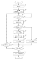
次に図2に示すフローチャートを用いて、本発明の撮影動作について説明する。 Next, the photographing operation of the present invention will be described using the flowchart shown in FIG.
図2は、本実施形態の撮像処理について説明したフローチャート図である。 FIG. 2 is a flowchart illustrating the imaging process of the present embodiment.
本撮像処理は、被写体の顔を検出し認識することにより、顔に合わせた撮像を行うものである。 In this imaging process, imaging according to the face is performed by detecting and recognizing the face of the subject.
ステップS201でシステム制御回路50は、撮像装置の電源をONして、撮像装置は撮影モードで起動する。 In step S201, the system control circuit 50 turns on the power of the imaging apparatus, and the imaging apparatus is activated in the imaging mode.
ステップS202で撮影者が撮影モードを顔認識連続撮影モードに設定をきりかえるとステップS203へ進む。 If the photographer changes the shooting mode to the face recognition continuous shooting mode in step S202, the process proceeds to step S203.
ステップS203では、システム制御回路50はシャッタースイッチSW1が押されたかどうかを判断する。SW1を押下されていなければ、SW1が押下されるまで処理を繰り返す。SW1が押下されていれば、ステップS204へ進む。 In step S203, the system control circuit 50 determines whether the shutter switch SW1 has been pressed. If SW1 is not pressed, the process is repeated until SW1 is pressed. If SW1 is pressed, the process proceeds to step S204.
ステップS204で顔認識回路58は被写体の顔領域を認識する処理を行う。 In step S204, the face recognition circuit 58 performs processing for recognizing the face area of the subject.
ステップS205で顔認識回路58は顔を認識できたかどうかを判断する。顔を認識できていれば、ステップS206へ進み、顔を認識できていなければ、ステップS209へ進む。 In step S205, the face recognition circuit 58 determines whether the face has been recognized. If the face can be recognized, the process proceeds to step S206. If the face cannot be recognized, the process proceeds to step S209.
ステップS206ではステップS204にて認識したそれぞれの顔に対して各種撮像パラメータを算出する。
本実施形態においては、被写体までの距離、顔領域の輝度値すなわち被写体輝度値(これよりBv値という)、露出値(これよりEv値という)、シャッタースピード値(これよりTv値という)、絞り値(これよりAv値という)を撮像パラメータとして算出しているが、撮像パラメータはこれらに限られるものではない。
In step S206, various imaging parameters are calculated for each face recognized in step S204.
In this embodiment, the distance to the subject, the luminance value of the face area, that is, the subject luminance value (hereinafter referred to as Bv value), the exposure value (hereinafter referred to as Ev value), the shutter speed value (hereinafter referred to as Tv value), the aperture Although the value (hereinafter referred to as the Av value) is calculated as the imaging parameter, the imaging parameter is not limited to these.
ステップS207では、ステップS206で算出した各種撮像パラメータ情報に基づき顔のグループ化を行い、かつグループに対して最適な撮像パラメータを設定する処理を行う。 In step S207, face grouping is performed based on the various imaging parameter information calculated in step S206, and processing for setting optimal imaging parameters for the group is performed.
ステップS208では、システム制御回路50は、顔を認識できたことを表示部54を介しユーザに文字・画像などを用いて通知する。また、音声を用いて撮影者に通知してもよい。
In step S208, the system control circuit 50 notifies the user through the
ステップS209では、システム制御回路50は顔を認識できなかったことを表示部54を介しユーザに文字・画像などを用い通知する。また、音声を用いて撮影者に通知してもよい。
In step S209, the system control circuit 50 notifies the user using characters / images or the like via the
ステップS210では、シャッタースイッチSW2が押されたかどうかをシステム制御回路50は判定をし、シャッタースイッチSW2が押下されていなければ、ステップS212へ進み、シャッタースイッチSW1が押下されてから所定時間が経過したかどうかの判定を行う。 In step S210, the system control circuit 50 determines whether or not the shutter switch SW2 has been pressed. If the shutter switch SW2 has not been pressed, the process proceeds to step S212, and a predetermined time has elapsed since the shutter switch SW1 was pressed. Judge whether or not.
ステップS212にて、シャッタースイッチSW1が押下されてから所定時間が経過していなければステップS210へ進み処理を行い、所定時間を超えていればステップS203に戻り処理を行う。 In step S212, if the predetermined time has not elapsed since the shutter switch SW1 was pressed, the process proceeds to step S210, and if the predetermined time has been exceeded, the process returns to step S203 to perform the process.
ステップS210にて、シャッタースイッチSW2が押下されていれば、システム制御回路50はステップS211にてグループ毎に撮像パラメータを設定し、それぞれのグループ毎に撮影を行い、画像を保存する。 If the shutter switch SW2 is pressed in step S210, the system control circuit 50 sets the imaging parameter for each group in step S211, performs shooting for each group, and stores the image.
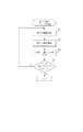
図3は、図2のステップS204の顔認識処理について詳細に説明したフローチャート図である。 FIG. 3 is a flowchart illustrating in detail the face recognition process in step S204 of FIG.
ステップS301では、フォーカシングを制御する焦点調節回路42を用い、システム制御回路50は焦点検出を行う。 In step S301, the focus adjustment circuit 42 that controls focusing is used, and the system control circuit 50 performs focus detection.
ステップS302では、システム制御回路50は撮像素子12から読み出した信号をA/D変換器16、画像処理回路20、メモリ制御回路22を介してメモリ30に画像データを書き込む。
In step S <b> 302, the system control circuit 50 writes the signal read from the
ステップS303では、ステップS302にてメモリ30に書き込まれた画像データから顔認識回路58が顔認識処理を行う。
In step S303, the face recognition circuit 58 performs face recognition processing from the image data written in the
図4は、図2のステップS206における認識した顔に対しての撮像パラメータ算出処理について詳細に説明したフローチャート図である。 FIG. 4 is a flowchart illustrating in detail the imaging parameter calculation processing for the recognized face in step S206 of FIG.
ステップS401では、顔の画像データを用いて所定の演算処理を行い、演算結果に基づいてシステム制御回路50が測距制御回路42に対して制御を行い、認識した顔までの被写体距離を算出する。 In step S401, predetermined calculation processing is performed using the face image data, and the system control circuit 50 controls the distance measurement control circuit 42 based on the calculation result to calculate the subject distance to the recognized face. .
ステップS402では、システム制御回路50は露出制御回路40に対して制御を行い、認識した顔の被写体輝度を算出する。 In step S402, the system control circuit 50 controls the exposure control circuit 40 to calculate the subject brightness of the recognized face.
ステップS403では、システム制御回路50は自動露出処理を行い、Av値・Tv値・利得値(これよりGain値という)を算出する。 In step S403, the system control circuit 50 performs an automatic exposure process to calculate an Av value, a Tv value, and a gain value (hereinafter referred to as a Gain value).
ステップS404では、システム制御回路50は認識した全ての顔に対し撮像パラメータを算出したかどうかを判断する。全ての顔に対し撮像パラメータを算出していなければ、システム制御回路50はステップS401からの処理を繰り返す。全ての顔に対し撮像パラメータを算出していれば、処理を終了する。 In step S404, the system control circuit 50 determines whether imaging parameters have been calculated for all recognized faces. If the imaging parameters have not been calculated for all the faces, the system control circuit 50 repeats the processing from step S401. If the imaging parameters have been calculated for all faces, the process ends.
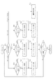
図5は、図2のステップS207における顔のグループ化を行い、グループ化されたグループに対してそれぞれ撮像パラメータを設定する処理について詳細に説明したフローチャート図である。 FIG. 5 is a flowchart illustrating in detail the process of grouping faces in step S207 of FIG. 2 and setting imaging parameters for each grouped group.
ステップS501では、システム制御回路50はステップS206で算出した各顔の撮像パラメータの内、被写体距離を基にしてグループ化を行う。 In step S501, the system control circuit 50 performs grouping based on the subject distance among the imaging parameters of each face calculated in step S206.
ステップS502では、システム制御回路50は、全ての顔に対してグループ化が完了しているかを判定する。全ての顔に対してグループ化が完了していれば、システム制御回路50は、ステップS503に処理を進める。全ての顔に対してグループ化が完了していなければ、システム制御回路50は、ステップ501に処理を戻す。 In step S502, the system control circuit 50 determines whether grouping has been completed for all faces. If grouping has been completed for all faces, the system control circuit 50 advances the process to step S503. If the grouping has not been completed for all the faces, the system control circuit 50 returns the process to step 501.
ステップS503では、システム制御回路50は、被写体距離によってグループ化されたグループ内に存在する顔を、ステップS206にて算出した顔領域に関する各種撮像パラメータの内の輝度値に基づきさらにグループ化する。このように、グループを細分化することにより、グループ毎に分けられた顔に適した撮像パラメータの精度が向上する。 In step S503, the system control circuit 50 further groups the faces existing in the group grouped according to the subject distance based on the luminance values of various imaging parameters related to the face area calculated in step S206. Thus, by subdividing the group, the accuracy of the imaging parameters suitable for the face divided for each group is improved.
ステップS504では、システム制御回路50は、全てのグループに対して、グループの細分化が完了しているかを判定する。全てのグループに対して細分化が完了していれば、システム制御回路50はステップS505に処理を進める。全てのグループに対して細分化が完了していなければ、システム制御回路50は、ステップS503に処理を戻す。 In step S504, the system control circuit 50 determines whether group subdivision has been completed for all groups. If segmentation has been completed for all groups, the system control circuit 50 advances the processing to step S505. If segmentation has not been completed for all groups, the system control circuit 50 returns the process to step S503.
ステップS505では、システム制御回路50はグループに存在する顔領域に関する各種撮像パラメータを算出し設定する。 In step S505, the system control circuit 50 calculates and sets various imaging parameters related to the face area existing in the group.
ステップS506では、システム制御回路50は全てのグループに対し撮像パラメータを設定したか否かを判定する。全てのグループに対し撮像パラメータを設定していれば、システム制御回路50は処理を終了させる。全てのグループに対し撮像パラメータを設定していなければ、システム制御回路50は、ステップS505に処理を戻す。 In step S506, the system control circuit 50 determines whether imaging parameters have been set for all groups. If the imaging parameters are set for all groups, the system control circuit 50 ends the process. If the imaging parameters are not set for all groups, the system control circuit 50 returns the process to step S505.
図6は図5のステップS501における被写体距離についてのグループ化の処理を詳細に説明したフローチャート図である。 FIG. 6 is a flowchart illustrating in detail the grouping process for the subject distance in step S501 of FIG.
ステップS601では、システム制御回路50は、ステップS401にて求めた被写体距離の判定を行う。被写体距離は、“A”が最も近く、“B”・“C”・“D”の順に遠くなり、どのグループにも適用されない被写体距離の場合、システム制御回路50は、ステップS611にてその顔を撮影非対象とする。 In step S601, the system control circuit 50 determines the subject distance obtained in step S401. When the subject distance is “A” which is the closest, and “B”, “C”, and “D” are in this order, and the subject distance is not applied to any group, the system control circuit 50 determines the face in step S611. Is not subject to photography.
被写体距離が“A”〜“B”の場合、ステップS702にて、システム制御回路50は、グループ1が存在するか判定する。グループ1が存在しなければステップS603にて、グループ1を作成し、処理をステップS604に進める。グループ1が存在すればステップS604の処理を行う。ステップS604では、システム制御回路50は、被写体の顔をグループ1に登録する。
If the subject distance is “A” to “B”, the system control circuit 50 determines whether
被写体距離が“B”〜“C”の場合、ステップS605にて、システム制御回路50は、グループ2が存在するか判定する。グループ2が存在しなければステップS606にて、グループ2を作成し、処理をステップS607へ進める。グループ2が存在すればステップS607の処理を行う。ステップS607では、システム制御回路50は、被写体の顔をグループ2に登録する。
If the subject distance is “B” to “C”, the system control circuit 50 determines whether
被写体距離が“C”〜“D”の場合、ステップS608にて、システム制御回路50は、グループ3が存在するか判定する。グループ3が存在しなければステップS609にて、グループ3を作成し、処理をステップS610に進める。グループ3が存在すればステップS610の処理を行う。ステップS610では、システム制御回路50は、被写体の顔をグループ3に登録する。
なお、本実施形態ではグループを3つとその他のグループで4つに分けたが、グループの分割数は4つに限られるわけではない。
When the subject distance is “C” to “D”, in step S608, the system control circuit 50 determines whether the
In the present embodiment, the group is divided into three groups and the other groups into four groups. However, the number of group divisions is not limited to four.
図7は、図5のステップS503における、被写体輝度に応じてグループを細分化する処理について詳細に説明したフローチャート図である。 FIG. 7 is a flowchart illustrating in detail the process of subdividing the group according to the subject brightness in step S503 of FIG.
ステップS701にて、システム制御回路50は、ステップS402にて求めた被写体輝度についての判定を行う。被写体輝度は、“P”が最も暗く、“Q”・“R”・“S”の順に明るくなり、どのグループにも適用されない被写体輝度を持つ顔の場合、ステップS711にて、システム制御回路50はその顔を撮影非対称とする。 In step S701, the system control circuit 50 determines the subject brightness obtained in step S402. As for the subject brightness, in the case of a face having “P” being the darkest and brightening in the order of “Q”, “R”, “S”, and subject brightness not applied to any group, the system control circuit 50 in step S711. Makes the face asymmetric.
被写体輝度が“P”〜“Q”の場合、ステップS702にて、システム制御回路50は、グループ(x)−1が存在するか判定する。グループ(x)−1が存在しなければステップS703にて、グループ(x)−1を作成し、処理をステップS704に進める。グループ(x)−1が存在すればステップS704の処理を行う。ステップS704にて、システム制御回路50は被写体の顔をグループ(x)−1に登録する。 When the subject brightness is “P” to “Q”, the system control circuit 50 determines whether group (x) −1 exists in step S702. If group (x) -1 does not exist, group (x) -1 is created in step S703, and the process proceeds to step S704. If group (x) -1 exists, the process of step S704 is performed. In step S704, the system control circuit 50 registers the face of the subject in the group (x) -1.
被写体輝度が“Q”〜“R”の場合、ステップS705にてシステム制御回路50は、グループ(x)−2が存在するか判定する。グループ(x)−2が存在しなければステップS706にて、グループ(x)−2を作成し、処理をステップS707に進める。グループ(x)−2が存在すればステップS707の処理を行う。ステップS707にて、システム制御部50は、被写体の顔をグループ(x)−2に登録する。 When the subject brightness is “Q” to “R”, the system control circuit 50 determines whether group (x) -2 exists in step S705. If group (x) -2 does not exist, group (x) -2 is created in step S706, and the process proceeds to step S707. If group (x) -2 exists, the process of step S707 is performed. In step S707, the system control unit 50 registers the face of the subject in the group (x) -2.
被写体輝度が“R”〜“S”の場合、ステップS708にてシステム制御部50は、グループ(x)−3が存在するか判定する。グループ(x)−3が存在しなければステップS709にて、グループ(x)−3を作成し、処理をステップS710に進める。グループ(x)−3が存在すればステップS710の処理を行う。ステップS710にてシステム制御部50は、被写体の顔をグループ(x)−3に登録する。 When the subject brightness is “R” to “S”, the system control unit 50 determines whether group (x) -3 exists in step S708. If group (x) -3 does not exist, group (x) -3 is created in step S709, and the process proceeds to step S710. If group (x) -3 exists, the process of step S710 is performed. In step S710, the system control unit 50 registers the face of the subject in the group (x) -3.
ステップS712では、システム制御部50は、グループ内の全ての顔に対してグループ化を行ったか判定する。グループ内の全ての顔に対してグループ化が完了していれば処理を終了する。グループ内の全ての顔に対してグループ化が完了していなければ、システム制御部50は処理をステップS701に戻す。 In step S712, the system control unit 50 determines whether all the faces in the group have been grouped. If grouping has been completed for all faces in the group, the process ends. If grouping has not been completed for all faces in the group, the system control unit 50 returns the process to step S701.
図8は、各グループに対し撮像パラメータを設定する処理を詳細に説明したフローチャート図である。 FIG. 8 is a flowchart illustrating in detail processing for setting imaging parameters for each group.
ステップS801では、システム制御部50は、グループ内の顔の平均輝度値を算出する。 In step S801, the system control unit 50 calculates the average luminance value of the faces in the group.
ステップS802では、システム制御部50は、ステップS801にて算出した輝度値からTv値・Av値・△Gain値を算出する。 In step S802, the system control unit 50 calculates a Tv value, an Av value, and a ΔGain value from the luminance value calculated in step S801.
ステップS803では、システム制御部50は、全てのグループに対し撮像パラメータを設定したかを判定する。システム制御部50が、全てのグループに対し撮像パラメータを設定していなければ、ステップS801からの処理を繰り返す。システム制御部50が、全てのグループに対し撮像パラメータを設定していれば、処理を終了する。なお、ステップS801にて被写体輝度値からTv値・Av値・△Gain値を算出する際に、撮影モードによって、Tv値・Av値・△Gain値を変化させてもよい。例えば、ポートレートモードであれば被写界深度を極力浅くするよう絞りを開放する(Av値を小さくする)設定を行う。またスポーツモードであればシャッタースピードを高速にする(Tv値を小さくする)ような設定を行う。上記以外の撮影モードにおいても撮影者が意図した撮像パラメータを算出するように処理する。 In step S803, the system control unit 50 determines whether imaging parameters have been set for all groups. If the system control unit 50 has not set imaging parameters for all groups, the processing from step S801 is repeated. If the system control unit 50 has set imaging parameters for all groups, the process ends. Note that when calculating the Tv value, Av value, and ΔGain value from the subject luminance value in Step S801, the Tv value, Av value, and ΔGain value may be changed depending on the shooting mode. For example, in the portrait mode, a setting is made to open the aperture (reduce the Av value) so as to make the depth of field as shallow as possible. In the sport mode, setting is made to increase the shutter speed (decrease the Tv value). In other shooting modes, processing is performed so as to calculate the imaging parameters intended by the photographer.
図17は、認識した顔領域に関する各種撮像パラメータをまとめた図の一例である。 FIG. 17 is an example of a diagram summarizing various imaging parameters related to the recognized face area.
構成要素は、顔の被写体距離、被写体輝度Bv値、露出Ev値、シャッター速度Tv値、絞りAv値である。 The components are the subject distance of the face, the subject brightness Bv value, the exposure Ev value, the shutter speed Tv value, and the aperture Av value.
ステップS501にて、被写体距離に基づき顔領域をグループ化するが、グループ1を0.5m〜1.5m、グループ2を1.5m〜2.5m、グループ3を2.5m〜3.5mとし、それ以外は撮影非対称とすると、グループ1は顔1と顔2、グループ2は顔3と顔4、グループ3はなし、撮影非対称は顔5、とグループ化することができる。
In step S501, the face areas are grouped based on the subject distance.
ステップS503にて被写体輝度Bv値から再度、顔をグループ化するが、グループx−1を2〜4、グループx−2を4〜6、グループx−3を6〜9とし、それ以外は撮影非対称とすると、グループ1の顔1と顔2は、グループ1−1はなし、グループ1−2は顔1、グループ1−3は顔2とグループ化することができる。グループ2の顔3と顔4は、グループ1−1はなし、グループ2−2は顔3と顔4、グループ2−3はなしとグループ化することができる。
In step S503, the faces are grouped again from the subject brightness Bv value, but the group x-1 is 2 to 4, the group x-2 is 4 to 6, the group x-3 is 6 to 9, and the others are photographed. If it is asymmetric,
ステップS505では、グループ1−2、グループ1−3、グループ2−2に対し、グループ毎にAv値・Tv値・Gain値を設定する。
そして、撮像パラメータの設定されたグループに対し、それぞれ撮影を行う。
In step S505, an Av value, a Tv value, and a Gain value are set for each of the groups 1-2, 1-3, and 2-2.
Then, photographing is performed for each group in which imaging parameters are set.
なお、本実施形態においては、被写体距離、及び被写体輝度に基づきそれぞれ3つずつにグループ化を行っているが、グループ化の数は3つに限られるわけでなく、距離の幅(最も遠い被写体距離と最も近い被写体距離との差分)や、輝度の幅(最も高い被写体輝度と最も低い被写体輝度との差分)によってグループの数を増減させてもよいし、予めユーザーが設定しておいてもよい。 In the present embodiment, grouping is performed in groups of three based on the subject distance and subject brightness, but the number of groupings is not limited to three, and the distance width (the farthest subject) The number of groups may be increased or decreased according to the difference between the distance and the nearest subject distance) or the brightness width (the difference between the highest subject brightness and the lowest subject brightness), or the user may set in advance Good.
なお、本発明はこれらの実施形態の構成に限定されるものではなく、請求項で示した機能、または実施形態がもつ機能が達成できる構成であれば、どのような形態であってもよいことは言うまでもない。 Note that the present invention is not limited to the configurations of these embodiments, and any configuration may be used as long as the functions indicated in the claims or the functions of the embodiments can be achieved. Needless to say.
またデジタルカメラに適用した例を述べているが、ビデオカメラや複写機などの様々な形態に適用してもよい。 Further, although an example applied to a digital camera is described, the present invention may be applied to various forms such as a video camera and a copying machine.
以上のように本実施形態では、撮像シーンの中から、被写体の顔を認識し、顔に対する被写体距離・被写体輝度などの各種撮像パラメータからグループ化を行い、グループ毎に最適な撮像パラメータを設定し、連続撮影することで、撮影者が所望する主被写体が最適な撮像パラメータで容易に撮影することが可能となる。 As described above, in this embodiment, the face of the subject is recognized from the imaging scene, and grouping is performed from various imaging parameters such as the subject distance to the face and the subject luminance, and the optimum imaging parameter is set for each group. By continuously photographing, it is possible to easily photograph the main subject desired by the photographer with optimum imaging parameters.
(第2の実施形態)
本実施の形態の動作を図面を参照して詳細に説明する。第1の実施形態と同じ処理を行うステップには同じステップ番号が割り当てられる。
(Second Embodiment)
The operation of the present embodiment will be described in detail with reference to the drawings. The same step number is assigned to the step that performs the same processing as in the first embodiment.
本実施形態が第1の実施形態と異なる点は、第1の実施形態が被写体距離、被写体輝度に基づき顔をグループ分けしているのに対して、本実施形態では、被写体距離と顔の座標位置に基づいてグループ分けを行っている点である。 This embodiment is different from the first embodiment in that the first embodiment groups faces based on subject distance and subject brightness, whereas in this embodiment, subject distance and face coordinates are different. The grouping is based on the position.
図9は、本実施形態の撮像処理を説明したフローチャート図である。 FIG. 9 is a flowchart illustrating the imaging process of the present embodiment.
図9は、第1の実施形態の図2の撮像処理を説明したフローチャートにおいて人の顔が検出された場合以降の内容についてが異なっており、それ以外の処理は図2と同じであるので、その部分に相当するステップS201からステップS205とステップS208からステップS209の説明は省略する。 FIG. 9 is different from FIG. 2 in the flowchart describing the imaging processing of the first embodiment when a human face is detected, and the other processing is the same as FIG. A description of steps S201 to S205 and steps S208 to S209 corresponding to this portion will be omitted.
第1の実施形態と同様に被写体の顔を認識できたと判断すると、ステップS901にて、システム制御回路50は、認識した顔領域に関する各種撮像パラメータを算出する。 If it is determined that the subject's face has been recognized as in the first embodiment, in step S901, the system control circuit 50 calculates various imaging parameters relating to the recognized face area.
ステップS902では、システム制御回路50は、ステップS901にて算出した各種撮像パラメータ情報を用い顔のグループ化を行い、各グループに対して撮像パラメータを新たに設定する処理を行う。 In step S902, the system control circuit 50 performs face grouping using the various imaging parameter information calculated in step S901, and performs processing for newly setting imaging parameters for each group.
ステップS210にて、システム制御回路50は、シャッタースイッチSW2が押されたか否かを判定する。ステップS210にて、SW2が押下されていなければ、ステップS212に処理を進め第1の実施形態と同様の処理を繰り返す。 In step S210, system control circuit 50 determines whether or not shutter switch SW2 has been pressed. In step S210, if SW2 is not pressed, the process proceeds to step S212, and the same process as in the first embodiment is repeated.
ステップS210にて、SW2が押下されていれば、システム制御回路50はステップS903へ処理を進める。 If SW2 is pressed in step S210, the system control circuit 50 advances the process to step S903.
ステップS903では、システム制御回路50はグループ毎に撮像パラメータを設定し撮影を行い、画像を保存する。 In step S903, the system control circuit 50 sets an imaging parameter for each group, performs imaging, and stores an image.
図10は、図9のステップS901における認識した顔領域に関する各種撮像パラメータ算出処理について詳細に説明したフローチャート図である。 FIG. 10 is a flowchart illustrating in detail the various imaging parameter calculation processing related to the recognized face area in step S901 in FIG.
ステップS401では、顔の画像データを用いて所定の演算処理を行い、演算結果に基づいてシステム制御回路50が測距制御回路42に対して制御を行い、認識した顔までの被写体距離を算出する。 In step S401, predetermined calculation processing is performed using the face image data, and the system control circuit 50 controls the distance measurement control circuit 42 based on the calculation result to calculate the subject distance to the recognized face. .
ステップS402では、システム制御回路50は露出制御回路40に対して制御を行い、認識した顔の被写体輝度を算出する。 In step S402, the system control circuit 50 controls the exposure control circuit 40 to calculate the subject brightness of the recognized face.
ステップS403では、システム制御回路50は自動露出処理を行い、Av値・Tv値・Gain値を算出する。 In step S403, the system control circuit 50 performs an automatic exposure process to calculate an Av value, a Tv value, and a Gain value.
ステップS1001では、システム制御回路50は認識した顔の座標位置を算出する。 In step S1001, the system control circuit 50 calculates the coordinate position of the recognized face.
ステップS404では、システム制御回路50は認識した全ての顔に対し撮像パラメータを算出したかどうかを判断する。全ての顔に対し撮像パラメータを算出していなければ、システム制御回路50はステップS401からの処理を繰り返す。全ての顔に対し撮像パラメータを算出していれば、処理を終了する。 In step S404, the system control circuit 50 determines whether imaging parameters have been calculated for all recognized faces. If the imaging parameters have not been calculated for all the faces, the system control circuit 50 repeats the processing from step S401. If the imaging parameters have been calculated for all faces, the process ends.
図11は、図9のステップS902における、顔のグループ化を行い、かつグループに対して撮像パラメータを設定する処理を詳細に説明したフローチャート図である。 FIG. 11 is a flowchart illustrating in detail the process of performing face grouping and setting imaging parameters for a group in step S902 of FIG.
ステップS501にて、システム制御回路50はステップS206で算出した各顔の撮像パラメータの内、被写体距離に基づきグループ化を行う。 In step S501, the system control circuit 50 performs grouping based on the subject distance among the imaging parameters of each face calculated in step S206.
ステップS502にて、システム制御回路50は全ての顔に対してグループ化を行ったかを判定する。全ての顔に対してグループ化を行っていれば、ステップS1101の処理を行う。行っていなければ、ステップ501の処理を戻す。
In step S502, the system control circuit 50 determines whether all the faces have been grouped. If all the faces have been grouped, the process of step S1101 is performed. If not, the process of
ステップS1101にて、システム制御回路50はグループ内に存在する顔の座標からグループを細分化する。グループを細分化することにより、顔に適した撮像パラメータの精度が向上する。 In step S1101, the system control circuit 50 subdivides the group from the coordinates of faces existing in the group. By subdividing the group, the accuracy of imaging parameters suitable for the face is improved.
ステップS504にて、システム制御回路50は全てのグループに対しグループの細分化をしたか判断する。全てのグループに対しグループの細分化を行っていれば、ステップS505の処理行う。行っていなければ、ステップS1101の処理を戻す。 In step S504, the system control circuit 50 determines whether the groups have been subdivided for all groups. If group subdivision has been performed for all groups, step S505 is performed. If not, the process of step S1101 is returned.
ステップS505では、システム制御回路50はグループに存在する顔から撮像パラメータを算出し設定する。 In step S505, the system control circuit 50 calculates and sets imaging parameters from the faces present in the group.
ステップS506にて、システム制御回路50は全てのグループに対し撮像パラメータを設定したか判定する。全てのグループ対し撮像パラメータを設定していれば、処理を終了する。設定してなければ、ステップS505の処理を戻す。 In step S506, the system control circuit 50 determines whether imaging parameters have been set for all groups. If imaging parameters have been set for all groups, the process ends. If not set, the process of step S505 is returned.
図12は、図11のステップS1101の被写体の顔座標データに応じてグループを細分化する処理を詳細に説明したフローチャート図である。 FIG. 12 is a flowchart illustrating in detail the process of subdividing the group according to the face coordinate data of the subject in step S1101 of FIG.
ステップS1201では、システム制御回路50は基準となる顔の座標値を取得する。なお、基準となる顔を選択する際に被写体距離によって顔に重み付けしてもよい。また測光方式やフォーカス枠に連動し重み付けを変化させてもよい。 In step S1201, the system control circuit 50 acquires a reference face coordinate value. Note that when selecting a reference face, the face may be weighted by subject distance. Further, the weight may be changed in conjunction with the photometry method or the focus frame.
ステップS1202では、システム制御回路50は顔の存在する範囲に基づき、グループの細分化の数を決定し、グループ化する座標領域を作成する。例えば、基準となる顔の座標(x、y)が(100、200)の場合、X座標プラス100・マイナス100、Y座標プラス100・マイナス100の座標(0、100)〜(300、400)までをグループ化する座標領域とする。
In step S1202, the system control circuit 50 determines the number of group subdivisions based on the range where the face exists, and creates a coordinate area to be grouped. For example, when the coordinate (x, y) of the reference face is (100, 200), the coordinates (0, 100) to (300, 400) of the X coordinate plus 100 /
ステップS1203では、システム制御回路50は画面内の他の顔の座標位置を取得する。 In step S1203, the system control circuit 50 acquires the coordinate positions of other faces in the screen.
ステップS1204では、システム制御回路50は基準の顔とそれ以外の他の顔の座標値とを比較し、グループ化する領域内に存在するかどうかの判定を行う。 In step S <b> 1204, the system control circuit 50 compares the reference face with the coordinate values of other faces and determines whether the face exists in the grouping area.
ステップS1204にて、グループ化する領域内に、グループ化すべき条件を満たす顔が存在しなければ、システム制御回路50は処理をステップS1207へ進める。 In step S1204, if there is no face that satisfies the grouping condition in the area to be grouped, the system control circuit 50 advances the process to step S1207.
ステップS1204にて、グループ化する領域内に、グループ化すべき条件を満たす顔が存在すれば、処理をステップS1206へ進め、システム制御回路50は同一グループとして顔を登録する。 In step S1204, if a face that satisfies the grouping condition exists in the grouping area, the process proceeds to step S1206, and the system control circuit 50 registers the face as the same group.
ステップS1206にて、システム制御回路50は、グループ内の全ての顔に対して座標値をチェックしたかどうかを判定する。 In step S1206, the system control circuit 50 determines whether coordinate values have been checked for all faces in the group.
ステップS1206にて、グループ内の全ての顔に対して座標をチェックしていなければ、処理をステップS1203へ戻す。 If the coordinates have not been checked for all the faces in the group in step S1206, the process returns to step S1203.
ステップS1206にて、グループ内の全ての顔に対して座標をチェックしていれば、処理を終了する。 If the coordinates have been checked for all faces in the group in step S1206, the process ends.
図13は、図11のステップS1101の顔座標データからマトリクス方式にて再度グループ化する処理を詳細に説明したフローチャート図である。 FIG. 13 is a flowchart illustrating in detail the process of grouping again from the face coordinate data in step S1101 of FIG. 11 by the matrix method.
ステップS1301にて、システム制御回路50はマトリクスを作成する。マトリクスとは例えば、縦3分割・横3分割にしたマトリクスを作成し、各マトリクスの座標値をもとめる。 In step S1301, the system control circuit 50 creates a matrix. As the matrix, for example, a matrix that is divided into three vertically and three horizontally is created, and the coordinate value of each matrix is obtained.
ステップS1302にて、システム制御回路50はマトリクス座標と顔の画像を比較する。 In step S1302, the system control circuit 50 compares the matrix coordinates with the face image.
ステップS1303にて、システム制御回路50は顔座標がある1つのマトリクス領域内に存在するかいなか判定する。 In step S1303, the system control circuit 50 determines whether the face coordinates exist within a certain matrix area.
顔座標がある1つのマトリクス領域内に存在する場合は処理をステップS1307へ進める。 If the face coordinates are present within one matrix area, the process advances to step S1307.
ステップS1307にて、システム制御回路50は顔が存在するマトリクスに顔を登録する。 In step S1307, the system control circuit 50 registers the face in the matrix in which the face exists.
一方顔座標がある1つのマトリクス領域内に存在しない場合は処理をステップS1305へ進める。 On the other hand, if the face coordinates do not exist within one matrix area, the process advances to step S1305.
ステップS1305にて、システム制御回路50は各マトリクスに占める顔面積を算出する。 In step S1305, the system control circuit 50 calculates the face area in each matrix.
ステップS1306にて、システム制御回路50は最も面積が広いマトリクスに顔を登録する。 In step S1306, the system control circuit 50 registers the face in the matrix having the largest area.
ステップS1308にて、システム制御回路50は全ての顔をマトリクス座標と比較したか否か判定する。比較していれば処理を終了する。比較していなければ、ステップS1302に処理を戻す。
図17は、認識した顔領域に関する各種撮像パラメータをまとめた一例を示す図である。
In step S1308, system control circuit 50 determines whether all faces have been compared with matrix coordinates. If it is compared, the process is terminated. If not compared, the process returns to step S1302.
FIG. 17 is a diagram illustrating an example of various imaging parameters related to the recognized face area.
顔の被写体距離、座標(x、y)、輝度Bv値、露出Ev値、シャッター速度Tv値、絞りAv値である。 The subject distance of the face, coordinates (x, y), luminance Bv value, exposure Ev value, shutter speed Tv value, and aperture Av value.
1901は撮像装置のモニタであり、縦3分割・横3分割したマトリクスを表している。縦座標を0、500、1000、1500、横座標を0、400、800、1200で分割する。1903は被写体の顔であり、1つのマトリクスに存在する顔である。1902も被写体の顔であるが、複数のマトリクスに跨った顔である。
ここで、複数のマトリックスに跨った被写体の顔1902の座標は(300,200)〜(550,430)であり、(0,0)〜(500,400)、(500,0)〜(1000、400)、(0,400)〜(500、800)、(500,400)〜(1000,800)の4つのマトリクスに跨っている。各マトリクスの面積を求めると、40000、10000、6000、1500となり、(0,0)〜(500,400)のマトリクスが最も広くなる。よって、顔1902は、マトリクス(0,0)〜(500,400)に登録する。
Here, the coordinates of the
ステップS501で被写体距離からグループ化するが、グループ1を0.5m〜1.5m、グループ2を1.5m〜2.5m、グループ3を2.5m〜3.5mとし、それ以外は撮影非対称とすると、グループ1は顔1と顔2、グループ2は顔3と顔4、グループ3はなし、撮影非対称は顔5とグループ化することができる。
In step S501, the subject distance is grouped, but
ステップS1101で座標(x、y)からグループを細分化するが、縦座標を0、500、1000、1500、横座標を0、400、800、1200と、縦3分割・横3分割したマトリクスとすると、グループ1の顔1と顔2は、共にマトリクス(0,0)〜(500,400)に存在する顔であるため、グループ1の細分化の必要はない。
In step S1101, the group is subdivided from the coordinates (x, y), but the ordinate is 0, 500, 1000, 1500, the abscissa is 0, 400, 800, 1200, Then, since the
グループ2の顔3と顔4はそれぞれ、マトリクス(0,0)〜(500,400)とマトリクス(1000,0)〜(1500,400)に存在する顔であるため、グループを細分化する。
結果、グループ1の顔1と顔2、グループ2の顔3、グループ3の顔4といったようにグループが細分化される。
Since the
As a result, the groups are subdivided, such as
ステップS505にて、システム制御回路50はグループ毎にAv値・Tv値・Gain値を設定する。そして、撮像パラメータの設定されたグループに対し、それぞれ撮影を行う。 In step S505, the system control circuit 50 sets an Av value, a Tv value, and a Gain value for each group. Then, photographing is performed for each group in which imaging parameters are set.
図15は、各グループに対し撮像パラメータを設定する処理を詳細に説明したフローチャート図である。 FIG. 15 is a flowchart illustrating in detail processing for setting imaging parameters for each group.
ステップS1501にて、システム制御回路50は、予め登録された顔が撮影した画面内に存在するかどうかを判定する。 In step S1501, the system control circuit 50 determines whether or not a pre-registered face exists in the captured screen.
登録した顔が撮影された画面内に存在するならば、ステップS1502にて、システム制御回路50は登録した顔の属するグループの撮像パラメータとして、登録した顔の撮像パラメータを設定する。なお、同一グループ内に登録した顔が複数ある場合は、複数の顔の撮像パラメータの平均値を求めることで対応する。 If the registered face is present in the captured screen, the system control circuit 50 sets the registered face imaging parameter as the imaging parameter of the group to which the registered face belongs in step S1502. In addition, when there are a plurality of registered faces in the same group, this is dealt with by obtaining an average value of imaging parameters of the plurality of faces.
登録した顔が撮影された画面内に存在しなければ、ステップS801にて、システム制御部50は、グループ内の顔の平均輝度値を算出する。 If the registered face does not exist in the captured screen, the system control unit 50 calculates the average luminance value of the faces in the group in step S801.
ステップS802ではシステム制御部50は、ステップS801にて算出した輝度値からTv値・Av値・△Gain値を算出する。 In step S802, the system control unit 50 calculates a Tv value, an Av value, and a ΔGain value from the luminance value calculated in step S801.
ステップS803ではシステム制御部50は、全てのグループに対し撮像パラメータを設定したかを判定する。システム制御部50が、全てのグループに対し撮像パラメータを設定していなければ、ステップS1501からの処理を繰り返す。システム制御部50が、全てのグループに対し撮像パラメータを設定していれば、処理を終了する。 In step S803, the system control unit 50 determines whether imaging parameters have been set for all groups. If the system control unit 50 has not set imaging parameters for all groups, the processing from step S1501 is repeated. If the system control unit 50 has set imaging parameters for all groups, the process ends.
図14は、撮影画像のExif圧縮データファイル構造を示した図である。 FIG. 14 is a diagram showing an Exif compressed data file structure of a captured image.
1401はJPEG圧縮方式のファイル記録形式であり、ファイルの先頭を表すSOIマーカ直後にアプリケーションマーカセグメント(APP1)を挿入し、APP1にExifの付加情報を記述する。
1402はAPP1の内部の構成であり、APP1はAPP1マーカ、Exifの識別コード、及び付属情報本体から構成される。付属情報は、File Headerを含むTIFF構造をとり、最大2つのIFD(0th IFD,1st IFD)を記録できる。0th IFDには、圧縮されている画像(主画像)に関する付属情報を記録する。1st IFDには、サムネイル画像を記録することができる。 Reference numeral 1402 denotes an internal configuration of APP1, and APP1 includes an APP1 marker, an Exif identification code, and an attached information main body. The attached information takes a TIFF structure including a file header and can record a maximum of two IFDs (0th IFD, 1st IFD). In the 0th IFD, auxiliary information regarding the compressed image (main image) is recorded. A thumbnail image can be recorded in the 1st IFD.
1403は0th IFD に Exif固有の付属情報を記録するためExif IFDである。Exif IFDの付属情報は、バージョンに関するものから始まりユーザ情報を記録することができる。そのユーザ情報内にメーカノート領域があり、メーカノート領域にはメーカが個別の情報を記入し、運用はメーカに任せられている。このメーカノート領域に認識した顔の座標を登録することにより画像再生時に認識した顔をユーザに通知することが可能となる。 1403 is an Exif IFD for recording Exif-specific attached information in the 0th IFD. The information attached to the Exif IFD can be recorded with user information starting from the version information. There is a manufacturer note area in the user information. The manufacturer enters individual information in the manufacturer note area, and the operation is left to the manufacturer. By registering the coordinates of the recognized face in the maker note area, it is possible to notify the user of the recognized face at the time of image reproduction.
図16は、画像再生時に認識した顔をユーザに通知した際のモニターイメージ図である。 FIG. 16 is a monitor image diagram when the user is notified of the face recognized at the time of image reproduction.
なお、本実施形態においては、被写体距離、及び被写の座標位置に基づきグループ化を行い、2回グループ化を行うことでグループの細分化を行っているが、撮影条件によってグループ化の回数を増減させても良い。 In this embodiment, grouping is performed based on the subject distance and the coordinate position of the subject, and grouping is performed by performing grouping twice. However, the number of times of grouping is determined depending on shooting conditions. It may be increased or decreased.
以上のように本実施形態では、複数人存在する被写体の顔を認識し、顔に対する被写体距離及び被写体の座標データなどの撮像パラメータから、近くに存在する顔をグループ化することにより、被写体それぞれに最適な撮影を簡単に行うことができる。 As described above, in the present embodiment, the faces of a plurality of subjects are recognized, and the nearby faces are grouped from the imaging parameters such as the subject distance to the face and the coordinate data of the subjects, so that each subject can be identified. Optimal shooting can be easily performed.
また、認識した顔を撮影者に通知することにより、撮影者が所望する顔を認識したかどうか確認することが可能となり、撮影の失敗を削減することができる。 In addition, by notifying the photographer of the recognized face, it is possible to check whether the photographer has recognized the desired face, thereby reducing shooting failures.
また、上述した各実施形態では顔認識を行うことによりグループ化を行っているが、顔の認識に限定されるわけでなく、公知の被写体認識技術を利用し被写体そのものの認識を行うことで、グループ分けを行っても良い。 Further, in each of the above-described embodiments, grouping is performed by performing face recognition, but it is not limited to face recognition, and by performing recognition of the subject itself using a known subject recognition technique, Grouping may be performed.
このように、本発明は、所定の条件を満たす被写体を複数検出し、これら検出した複数の被写体を別の条件を用いて更に複数のグループに分け、そして、この複数のグループのそれぞれに対して、撮影パラメータを設定して撮影を行う、ことを満たすものであれば上記の実施形態に限定されるものではない。 As described above, the present invention detects a plurality of subjects that satisfy a predetermined condition, further divides the detected plurality of subjects into a plurality of groups using different conditions, and for each of the plurality of groups. The present invention is not limited to the above-described embodiment as long as the shooting parameters are set and shooting is performed.
また、本発明の目的は、前述した実施形態の機能を実現するソフトウェアのプログラムコードを記録した記憶媒体(または記録媒体)を、システムあるいは装置に供給し、そのシステムあるいは装置のコンピュータ(またはCPUやMPU)が記憶媒体に格納されたプログラムコードを読み出し実行することによっても、達成されることは言うまでもない。この場合、記憶媒体から読み出されたプログラムコード自体が前述した実施形態の機能を実現することになり、そのプログラムコードを記憶した記憶媒体は本発明を構成することになる。また、コンピュータが読み出したプログラムコードを実行することにより、前述した実施形態の機能が実現されるだけでなく、そのプログラムコードの指示に基づき、コンピュータ上で稼働しているオペレーティングシステム(OS)などが実際の処理の一部または全部を行い、その処理によって前述した実施形態の機能が実現される場合も含まれることは言うまでもない。ここでプログラムコードを記憶する記憶媒体としては、例えば、フレキシブルディスク、ハードディスク、ROM、RAM、磁気テープ、不揮発性のメモリカード、CD−ROM、CD−R、DVD、光ディスク、光磁気ディスク、MOなどが考えられる。また、LAN(ローカル・エリア・ネットワーク)やWAN(ワイド・エリア・ネットワーク)などのコンピュータネットワークを、プログラムコードを供給するために用いることができる。 Another object of the present invention is to supply a storage medium (or recording medium) in which a program code of software that realizes the functions of the above-described embodiments is recorded to a system or apparatus, and the computer (or CPU or CPU) of the system or apparatus. Needless to say, this can also be achieved by the MPU) reading and executing the program code stored in the storage medium. In this case, the program code itself read from the storage medium realizes the functions of the above-described embodiments, and the storage medium storing the program code constitutes the present invention. Further, by executing the program code read by the computer, not only the functions of the above-described embodiments are realized, but also an operating system (OS) running on the computer based on the instruction of the program code. It goes without saying that a case where the function of the above-described embodiment is realized by performing part or all of the actual processing and the processing is included. Examples of the storage medium for storing the program code include a flexible disk, hard disk, ROM, RAM, magnetic tape, nonvolatile memory card, CD-ROM, CD-R, DVD, optical disk, magneto-optical disk, MO, and the like. Can be considered. Also, a computer network such as a LAN (Local Area Network) or a WAN (Wide Area Network) can be used to supply the program code.
10 レンズバリア
11 撮影レンズ
12 シャッター
14 撮像素子
16 A/D変換器
18 タイミング発生回路
20 画像処理回路
22 メモリ制御回路
24 画像表示メモリ
26 D/A変換器
28 画像表示部
30 メモリ
32 圧縮・伸長回路
33 通信回路
40 露出制御回路
42 測距制御回路
44 ズーム制御回路
46 バリア制御回路
48 フラッシュ装置
50 システム制御回路
52 システムメモリ
54 表示部
56 不揮発性メモリ
58 顔認識回路
59 画像合成回路
60 メインスイッチ
62 シャッタースイッチSW1
64 シャッタースイッチSW2
70 操作部
72 モードダイアルスイッチ
80 電源制御回路
82 コネクタ
86 電源装置
90 記録媒体用インターフェース
99 外部記録媒体
100 撮像装置
DESCRIPTION OF
64 Shutter switch SW2
DESCRIPTION OF SYMBOLS 70
Claims (7)
前記撮像手段により得られた画像データから被写体が存在する複数の領域を認識する認識手段と、
前記認識手段により認識された前記複数の領域の画像データから被写体距離および被写体輝度を算出する算出手段と、
前記算出手段によって算出された前記被写体距離および前記被写体輝度に基づき、前記複数の領域をグループ化するグループ化手段と、
前記グループ化手段によってグループ化されたグループ毎にそれぞれ撮像パラメータを設定する設定手段とを有し、
前記設定手段により設定されたグループ毎の撮像パラメータに基づいて、撮影することを特徴とする撮像装置。 Imaging means for converting the subject image into an electrical signal to obtain image data;
Recognizing means for recognizing a plurality of areas where a subject exists from image data obtained by the imaging means;
Calculation means for calculating subject distance and subject brightness from the image data of the plurality of areas recognized by the recognition means;
Grouping means for grouping the plurality of regions based on the subject distance and the subject brightness calculated by the calculating means;
Setting means for setting imaging parameters for each group grouped by the grouping means,
An imaging apparatus that performs imaging based on imaging parameters for each group set by the setting unit.
前記撮像手段により得られた画像データから被写体が存在する複数の領域を認識する認識手段と、
前記認識手段により認識された前記複数の領域の画像データから被写体距離および被写体の座標値を算出する算出手段と、
前記算出手段によって算出された前記被写体距離および前記被写体の座標値に基づき、前記複数の領域をグループ化するグループ化手段と、
前記グループ化手段によってグループ化されたグループ毎にそれぞれ撮像パラメータを設定する設定手段とを有し、
前記設定手段により設定されたグループ毎の撮像パラメータに基づいて、撮影することを特徴とする撮像装置。 Imaging means for converting the subject image into an electrical signal to obtain image data;
Recognizing means for recognizing a plurality of areas where a subject exists from image data obtained by the imaging means;
Calculating means for calculating a subject distance and a coordinate value of the subject from the image data of the plurality of areas recognized by the recognition means;
Grouping means for grouping the plurality of regions based on the subject distance and the coordinate value of the subject calculated by the calculating means;
Setting means for setting imaging parameters for each group grouped by the grouping means,
An imaging apparatus that performs imaging based on imaging parameters for each group set by the setting unit.
前記撮像工程において得られた画像データから被写体が存在する複数の領域を認識する認識工程と、
前記認識工程において認識された前記複数の領域の画像データから被写体距離および被写体輝度を算出する算出工程と、
前記算出工程において算出された前記被写体距離および前記被写体輝度に基づき、前記複数の領域をグループ化するグループ化工程と、
前記グループ化工程においてグループ化されたグループ毎にそれぞれ撮像パラメータを設定する設定工程と、
前記設定工程において設定されたグループ毎の撮像パラメータに基づいて、撮影を行う撮影工程とを有することを特徴とする撮像装置の制御方法。 An imaging step of converting a subject image into an electrical signal to obtain image data;
A recognition step for recognizing a plurality of regions where a subject exists from the image data obtained in the imaging step;
A calculation step of calculating subject distance and subject luminance from the image data of the plurality of regions recognized in the recognition step;
A grouping step of grouping the plurality of regions based on the subject distance and the subject luminance calculated in the calculation step;
A setting step of setting imaging parameters for each group grouped in the grouping step;
An imaging apparatus control method comprising: an imaging process for performing imaging based on an imaging parameter for each group set in the setting process.
前記撮像工程において得られた画像データから被写体が存在する複数の領域を認識する認識工程と、
前記認識工程において認識された前記複数の領域の画像データから被写体距離および被写体の座標値を算出する算出工程と、
前記算出工程において算出された前記被写体距離および前記被写体の座標値に基づき、前記複数の領域をグループ化するグループ化工程と、
前記グループ化工程においてグループ化されたグループ毎にそれぞれ撮像パラメータを設定する設定工程と、
前記設定工程において設定されたグループ毎の撮像パラメータに基づいて、撮影を行う撮影工程とを有することを特徴とする撮像装置の制御方法。 An imaging step of converting a subject image into an electrical signal to obtain image data;
A recognition step for recognizing a plurality of regions where a subject exists from the image data obtained in the imaging step;
A calculation step of calculating a subject distance and a coordinate value of the subject from the image data of the plurality of regions recognized in the recognition step;
A grouping step for grouping the plurality of regions based on the subject distance and the coordinate value of the subject calculated in the calculation step;
A setting step of setting imaging parameters for each group grouped in the grouping step;
An imaging apparatus control method comprising: an imaging process for performing imaging based on an imaging parameter for each group set in the setting process .
Priority Applications (1)
| Application Number | Priority Date | Filing Date | Title |
|---|---|---|---|
| JP2005169394A JP4574459B2 (en) | 2005-06-09 | 2005-06-09 | Image capturing apparatus, control method therefor, program, and storage medium |
Applications Claiming Priority (1)
| Application Number | Priority Date | Filing Date | Title |
|---|---|---|---|
| JP2005169394A JP4574459B2 (en) | 2005-06-09 | 2005-06-09 | Image capturing apparatus, control method therefor, program, and storage medium |
Publications (3)
| Publication Number | Publication Date |
|---|---|
| JP2006345254A JP2006345254A (en) | 2006-12-21 |
| JP2006345254A5 JP2006345254A5 (en) | 2008-07-24 |
| JP4574459B2 true JP4574459B2 (en) | 2010-11-04 |
Family
ID=37641870
Family Applications (1)
| Application Number | Title | Priority Date | Filing Date |
|---|---|---|---|
| JP2005169394A Active JP4574459B2 (en) | 2005-06-09 | 2005-06-09 | Image capturing apparatus, control method therefor, program, and storage medium |
Country Status (1)
| Country | Link |
|---|---|
| JP (1) | JP4574459B2 (en) |
Families Citing this family (17)
| Publication number | Priority date | Publication date | Assignee | Title |
|---|---|---|---|---|
| JP5023757B2 (en) * | 2007-03-28 | 2012-09-12 | カシオ計算機株式会社 | Imaging apparatus and program |
| JP4750063B2 (en) * | 2007-03-28 | 2011-08-17 | 富士フイルム株式会社 | Imaging apparatus and imaging method |
| JP4888191B2 (en) * | 2007-03-30 | 2012-02-29 | 株式会社ニコン | Imaging device |
| JP5019939B2 (en) | 2007-04-19 | 2012-09-05 | パナソニック株式会社 | Imaging apparatus and imaging method |
| JP2009156888A (en) * | 2007-12-25 | 2009-07-16 | Sanyo Electric Co Ltd | Speech corrector and imaging apparatus equipped with the same, and sound correcting method |
| JP5239601B2 (en) * | 2007-09-28 | 2013-07-17 | カシオ計算機株式会社 | Imaging apparatus and program |
| JP5381060B2 (en) * | 2008-02-05 | 2014-01-08 | 株式会社リコー | Imaging apparatus and image processing method thereof |
| JP5043736B2 (en) | 2008-03-28 | 2012-10-10 | キヤノン株式会社 | Imaging apparatus and control method thereof |
| US8477207B2 (en) | 2008-06-06 | 2013-07-02 | Sony Corporation | Image capturing apparatus, image capturing method, and computer program |
| JP5251547B2 (en) | 2008-06-06 | 2013-07-31 | ソニー株式会社 | Image photographing apparatus, image photographing method, and computer program |
| EP2527797A1 (en) | 2010-01-20 | 2012-11-28 | Canon Kabushiki Kaisha | Displacement detection device, and error correction method for scale for displacement detection device |
| US8558923B2 (en) | 2010-05-03 | 2013-10-15 | Canon Kabushiki Kaisha | Image capturing apparatus and method for selective real time focus/parameter adjustment |
| JP5914055B2 (en) | 2012-03-06 | 2016-05-11 | キヤノン株式会社 | Imaging device |
| JP5488639B2 (en) * | 2012-04-27 | 2014-05-14 | カシオ計算機株式会社 | Imaging apparatus, imaging method, and program |
| CN102843463B (en) * | 2012-08-02 | 2015-06-24 | 广东欧珀移动通信有限公司 | New photographing interaction method and mobile intelligent terminal |
| JP6281426B2 (en) * | 2014-07-08 | 2018-02-21 | 富士通株式会社 | Image display control device, image display control method, and image display control program |
| US11057573B2 (en) | 2017-12-20 | 2021-07-06 | Texas Instruments Incorporated | Multi camera image processing |
Citations (3)
| Publication number | Priority date | Publication date | Assignee | Title |
|---|---|---|---|---|
| JP2001215403A (en) * | 2000-02-01 | 2001-08-10 | Canon Inc | Image pickup device and automatic focus detection method |
| JP2003344891A (en) * | 2002-05-23 | 2003-12-03 | Canon Inc | Automatic photographing mode setting camera |
| JP2005128156A (en) * | 2003-10-22 | 2005-05-19 | Canon Inc | Focusing device and method |
Family Cites Families (3)
| Publication number | Priority date | Publication date | Assignee | Title |
|---|---|---|---|---|
| JPS52156624A (en) * | 1976-06-22 | 1977-12-27 | Fuji Photo Film Co Ltd | Detection of skin color of color film |
| JP2695067B2 (en) * | 1991-05-23 | 1997-12-24 | 富士写真フイルム株式会社 | Method of extracting data of human face and method of determining exposure amount |
| JP3335419B2 (en) * | 1993-05-25 | 2002-10-15 | オリンパス光学工業株式会社 | Camera ranging device |
-
2005
- 2005-06-09 JP JP2005169394A patent/JP4574459B2/en active Active
Patent Citations (3)
| Publication number | Priority date | Publication date | Assignee | Title |
|---|---|---|---|---|
| JP2001215403A (en) * | 2000-02-01 | 2001-08-10 | Canon Inc | Image pickup device and automatic focus detection method |
| JP2003344891A (en) * | 2002-05-23 | 2003-12-03 | Canon Inc | Automatic photographing mode setting camera |
| JP2005128156A (en) * | 2003-10-22 | 2005-05-19 | Canon Inc | Focusing device and method |
Also Published As
| Publication number | Publication date |
|---|---|
| JP2006345254A (en) | 2006-12-21 |
Similar Documents
| Publication | Publication Date | Title |
|---|---|---|
| JP4574459B2 (en) | Image capturing apparatus, control method therefor, program, and storage medium | |
| JP5046788B2 (en) | Imaging apparatus and control method thereof | |
| JP5004726B2 (en) | Imaging apparatus, lens unit, and control method | |
| JP4799511B2 (en) | Imaging apparatus and method, and program | |
| JP4644883B2 (en) | Imaging device | |
| US20110102621A1 (en) | Method and apparatus for guiding photographing | |
| KR101700366B1 (en) | Digital photographing apparatus and control method thereof | |
| US8610817B2 (en) | Image-capturing apparatus and control method therefor | |
| JP2007282118A (en) | Electronic camera and image processing apparatus | |
| JP2007081732A (en) | Imaging apparatus | |
| JP4725854B2 (en) | Image display device and image display method | |
| JP2006295316A (en) | Imaging apparatus, imaging method, program, and storage medium | |
| JP5075288B2 (en) | Imaging apparatus and control method thereof | |
| JP2008011264A (en) | Imaging apparatus, its control method, program, and storage medium | |
| JP5968386B2 (en) | Imaging apparatus and control method thereof | |
| JP6200194B2 (en) | Imaging apparatus, control method therefor, and program | |
| JP6526270B2 (en) | Image pickup apparatus and control method thereof | |
| JP5224951B2 (en) | Image processing apparatus, method, and program | |
| JP2016167088A (en) | Imaging device and control method of the same | |
| JP5004876B2 (en) | Imaging device | |
| JP2008252321A (en) | Imaging apparatus, imaging method, and imaging program | |
| JP2008011244A (en) | Imaging apparatus, its control method, and program | |
| JP2016208206A (en) | Recording apparatus | |
| JP6278702B2 (en) | Imaging apparatus, control method therefor, and program | |
| JP2015037289A (en) | Image recording device, control method of the same, and program |
Legal Events
| Date | Code | Title | Description |
|---|---|---|---|
| A521 | Request for written amendment filed |
Free format text: JAPANESE INTERMEDIATE CODE: A523 Effective date: 20080606 |
|
| A621 | Written request for application examination |
Free format text: JAPANESE INTERMEDIATE CODE: A621 Effective date: 20080606 |
|
| RD04 | Notification of resignation of power of attorney |
Free format text: JAPANESE INTERMEDIATE CODE: A7424 Effective date: 20100201 |
|
| A977 | Report on retrieval |
Free format text: JAPANESE INTERMEDIATE CODE: A971007 Effective date: 20100607 |
|
| A131 | Notification of reasons for refusal |
Free format text: JAPANESE INTERMEDIATE CODE: A131 Effective date: 20100615 |
|
| RD01 | Notification of change of attorney |
Free format text: JAPANESE INTERMEDIATE CODE: A7421 Effective date: 20100630 |
|
| A521 | Request for written amendment filed |
Free format text: JAPANESE INTERMEDIATE CODE: A523 Effective date: 20100730 |
|
| TRDD | Decision of grant or rejection written | ||
| A01 | Written decision to grant a patent or to grant a registration (utility model) |
Free format text: JAPANESE INTERMEDIATE CODE: A01 Effective date: 20100817 |
|
| A01 | Written decision to grant a patent or to grant a registration (utility model) |
Free format text: JAPANESE INTERMEDIATE CODE: A01 |
|
| A61 | First payment of annual fees (during grant procedure) |
Free format text: JAPANESE INTERMEDIATE CODE: A61 Effective date: 20100818 |
|
| R150 | Certificate of patent or registration of utility model |
Ref document number: 4574459 Country of ref document: JP Free format text: JAPANESE INTERMEDIATE CODE: R150 Free format text: JAPANESE INTERMEDIATE CODE: R150 |
|
| FPAY | Renewal fee payment (event date is renewal date of database) |
Free format text: PAYMENT UNTIL: 20130827 Year of fee payment: 3 |