JP2007081732A - Imaging apparatus - Google Patents
Imaging apparatus Download PDFInfo
- Publication number
- JP2007081732A JP2007081732A JP2005265936A JP2005265936A JP2007081732A JP 2007081732 A JP2007081732 A JP 2007081732A JP 2005265936 A JP2005265936 A JP 2005265936A JP 2005265936 A JP2005265936 A JP 2005265936A JP 2007081732 A JP2007081732 A JP 2007081732A
- Authority
- JP
- Japan
- Prior art keywords
- area
- face
- face detection
- detection
- imaging apparatus
- Prior art date
- Legal status (The legal status is an assumption and is not a legal conclusion. Google has not performed a legal analysis and makes no representation as to the accuracy of the status listed.)
- Pending
Links
Images


Abstract
Description
入射した光を電気信号に変換する撮像素子の出力をデジタル値に変換して画像データを得る撮像装置に関する。 The present invention relates to an imaging device that obtains image data by converting an output of an imaging element that converts incident light into an electrical signal into a digital value.
従来、人物撮影を行う場合において、主被写体である人物とその背景のコントラストの関係から焦点が人物に合わずに、背景に合ってしまうという問題があった。このような問題を解決するために、画面内の顔を検出し、検出した顔の位置に合焦させることで、人物に焦点を合わせる撮像装置が開発されている(特許文献1参照)。 Conventionally, when taking a picture of a person, there is a problem that the focus is not on the person but on the background because of the contrast between the person who is the main subject and the background. In order to solve such a problem, an imaging apparatus that focuses on a person by detecting a face in the screen and focusing on the position of the detected face has been developed (see Patent Document 1).
なお、画像データからの顔検出については、非特許文献1,2に記載されたものが知られている。更に、特許文献2〜5に記載されている手法で目を検出することにより、顔の位置や大きさを推定することもできる。
しかしこのような撮像装置では、画面のどこに人物がいるかわからないため、画面全体を顔検出エリアとして設定していた。このため、顔検出処理に時間が多くかかっていた。このような顔検出に要する時間は直接シャッタータイムラグへ影響するため、顔検出にかかる時間を低減する必要がある。 However, in such an imaging apparatus, the whole screen is set as a face detection area because it is not known where the person is on the screen. For this reason, the face detection process takes a long time. Since the time required for face detection directly affects the shutter time lag, it is necessary to reduce the time required for face detection.
本発明は上記の課題に鑑みてなされたものであり、撮像装置における顔検出にかかる時間を低減させることによりシャッターレリーズタイムラグを低減させることを目的とする。 The present invention has been made in view of the above problems, and an object thereof is to reduce the shutter release time lag by reducing the time required for face detection in the imaging apparatus.
入射した光を電気信号に変換する撮像素子の出力をデジタル値に変換して画像データを得る撮像装置において、
画像データ中の複数の部分領域を示す領域データを保持する保持手段と、
前記保持手段に保持された領域データによって示される部分領域を画像データより切り出す切り出し手段と、
前記切り出し手段で切り出された部分領域内の画像データから顔領域を検出する検出手段と、
前記検出手段で検出された顔領域内の画像データに基づいて当該撮像装置の制御を行う制御手段とを備えることを特徴とする撮像装置。
In an imaging device that obtains image data by converting the output of an imaging device that converts incident light into an electrical signal into a digital value,
Holding means for holding area data indicating a plurality of partial areas in the image data;
Clipping means for cutting out the partial area indicated by the area data held in the holding means from image data;
Detecting means for detecting a face area from the image data in the partial area cut out by the cutting means;
An imaging apparatus comprising: control means for controlling the imaging apparatus based on image data in the face area detected by the detection means.
撮像装置における顔検出にかかる時間を低減させ、シャッターレリーズタイムラグを低減させることができる。 The time required for face detection in the imaging apparatus can be reduced, and the shutter release time lag can be reduced.
以下、添付の図面を参照して本発明の好適な実施形態を説明する。 Hereinafter, preferred embodiments of the present invention will be described with reference to the accompanying drawings.
<第1実施形態>
図1は、第1実施形態による撮像装置の構成例を示すブロック図である。図1において、100は第1実施形態の撮像装置を示している。
<First Embodiment>
FIG. 1 is a block diagram illustrating a configuration example of an imaging apparatus according to the first embodiment. In FIG. 1,
撮像装置100において、撮影レンズ10、絞り機能を備えるシャッター12を通過した光学像は撮像素子14に到達する。撮像素子14は、その撮像面に到達した光学像を電気信号に変換し、アナログ信号を出力する。A/D変換器16は撮像素子14からのアナログ信号出力をディジタル信号に変換する。タイミング発生回路18は、撮像素子14、A/D変換器16、D/A変換器26にクロック信号や制御信号を供給する。また、タイミング発生回路18は、メモリ制御回路22及びシステム制御回路50により制御される。
In the
画像処理回路20は、A/D変換器16からのデータ或いはメモリ制御回路22からのデータに対して所定の画素補間処理や色変換処理を行う。また、画像処理回路20において撮像した画像データを用いて所定の演算処理を行い、システム制御回路50がこの演算結果に基づいて露光制御部40や測距制御部42を制御する。この制御により、TTL(スルー・ザ・レンズ)方式のAF(オートフォーカス)処理、AE(自動露出)処理、EF(フラッシュプリ発光)処理が行われる。さらに、画像処理回路20においては、撮像した画像データを用いて所定の演算処理を行い、得られた演算結果に基づいてTTL方式のAWB(オートホワイトバランス)処理も行っている。
The
メモリ制御回路22は、A/D変換器16、タイミング発生回路18、画像処理回路20、画像表示メモリ24、D/A変換器26、メモリ30、圧縮・伸長回路32を制御する。A/D変換器16のデータが画像処理回路20、メモリ制御回路22を介して、或いはA/D変換器16のデータが直接メモリ制御回路22を介して、画像表示メモリ24或いはメモリ30に書き込まれる。画像表示メモリ24に書き込まれた表示用の画像データはD/A変換器26を介して画像表示部28により表示される。なお、画像表示部28は、例えばTFT液晶表示器等から成る。
The
画像表示部28を用いて撮像した画像データを逐次表示すれば、電子ファインダ機能を実現することが可能である。また、画像表示部28は、システム制御回路50の指示により任意に表示をON/OFFすることが可能であり、表示をOFFにした場合には画像処理装置100の電力消費を大幅に低減することが出来る。
If the image data captured using the
メモリ30は撮影した静止画像や動画像を格納するためのメモリであり、所定枚数の静止画像や所定時間の動画像を格納するのに十分な記憶量を備えている。これにより、複数枚の静止画像を連続して撮影する連射撮影やパノラマ撮影の場合にも、高速かつ大量の画像書き込みをメモリ30に対して行うことが可能となる。また、メモリ30はシステム制御回路50の作業領域としても使用することが可能である。
The
圧縮・伸長回路32は適応離散コサイン変換(ADCT)等により画像データを圧縮伸長する。圧縮・伸長回路32は、メモリ30に格納された画像を読み込んで圧縮処理或いは伸長処理を行い、処理を終えたデータをメモリ30に書き込む。
The compression /
露光制御部40は絞り機能を備えるシャッター12を制御するとともに、フラッシュ48と連携することによりフラッシュ調光機能も有する。測距部42は撮影レンズ10のフォーカシングを制御する。ズーム制御部44は撮影レンズ10のズーミングを制御する。バリア制御部46はバリアである保護部102の動作を制御する。フラッシュ48は、AF補助光の投光機能、フラッシュ調光機能も有する。
The
露光制御部40、測距制御部42はTTL方式を用いて制御されている。すなわち、撮像した画像データを画像処理回路20によって演算した演算結果に基づき、システム制御回路50が露光制御部40、測距制御部42に対して制御を行う。
The
システム制御回路50は撮像装置100の全体を制御する。メモリ52はシステム制御回路50の動作用の定数、変数、プログラム等を記憶するメモリである。表示部54は、システム制御回路50におけるプログラムの実行に応じて、文字、画像、音声等を用いて動作状態やメッセージ等を表示する液晶表示装置やスピーカー等を含む。表示部54は、撮像装置100の操作部近辺の視認し易い位置に単数或いは複数個所設置され、例えばLCDやLED、発音素子等の組み合わせにより構成されている。また、表示部54は、その一部の機能が光学ファインダ104内に設置されている。
A
表示部54の表示内容のうち、LCD等に表示するものとしては、シングルショット/連写撮影表示、セルフタイマー表示、圧縮率表示、記録画素数表示、記録枚数表示、残撮影可能枚数表示、シャッタースピード表示、絞り値表示、露出補正表示、フラッシュ表示、赤目緩和表示、マクロ撮影表示、ブザー設定表示、時計用電池残量表示、電池残量表示、エラー表示、複数桁の数字による情報表示、記録媒体200及び210の着脱状態表示、通信I/F動作表示、日付け・時刻表示、等がある。また、表示部54の表示内容のうち、光学ファインダ104内に表示するものとしては、合焦表示、手振れ警告表示、フラッシュ充電表示、シャッタースピード表示、絞り値表示、露出補正表示、等がある。
Among the display contents of the
不揮発性メモリ56は電気的に消去・記録が可能であり、例えばEEPROM等により構成されている。60、62、64、66、68及び70は、システム制御回路50の各種の動作指示を入力するための指示入力部を構成する。指示入力部は、スイッチやダイアル、タッチパネル、視線検知によるポインティング、音声認識装置等の単数或いは複数の組み合わせで構成される。ここで、これら指示入力部の具体的な説明を行う。
The
モードダイアルスイッチ60は、電源オフ、自動撮影モード、撮影モード、パノラマ撮影モード、再生モード、マルチ画面再生・消去モード、PC接続モード等の各機能モードを切り替え設定することが出来る。
The
シャッタースイッチ62は、シャッターボタンの操作途中(シャッターボタンの半押し)でONとなりSW1信号を発生する。システム制御部50は、このSW1信号により、顔検出処理、AF(オートフォーカス)処理、AE(自動露出)処理、AWB(オートホワイトバランス)処理、EF(フラッシュプリ発光)処理等の動作を開始する。シャッタースイッチ64は、シャッターボタンの操作完了(シャッターボタンの全押し)でONとなり、SW2信号を発生する。このSW2信号により、露光処理、現像処理及び記録処理を含む一連の処理の動作開始を指示する。なお、露光処理では、撮像素子12から読み出された信号が、A/D変換器16、メモリ制御回路22を介して画像データとしてメモリ30に書き込まれる。現像処理では、画像処理回路20やメモリ制御回路22での演算を用いた画像処理が行われる。また、記録処理では、メモリ30から画像データを読み出し、圧縮・伸長回路32で圧縮を行い、記録媒体200或いは210に画像データを書き込む。
The shutter switch 62 is turned on during the operation of the shutter button (half-pressing the shutter button) to generate the SW1 signal. The
画像表示ON/OFFスイッチ66は、画像表示部28のON/OFFを設定することが出来る。この機能により、光学ファインダ104を用いて撮影を行う際に、TFT液晶表示器等から成る画像表示部への電流供給を遮断することができ、省電力を図ることが可能となる。クイックレビューON/OFFスイッチ68は、撮影直後に撮影した画像データを自動再生するクイックレビュー機能を設定する。なお、本実施形態では特に、画像表示部28をOFFとした場合におけるクイックレビュー機能の設定をする機能も備えるものとする。
The image display ON /
操作部70は各種ボタンやタッチパネル等からなる。操作部70が備える操作ボタンとしては、例えば、メニューボタン、セットボタン、マクロボタン、マルチ画面再生改ページボタン、フラッシュ設定ボタン、単写/連写/セルフタイマー切り替えボタン、メニュー移動+(プラス)ボタン、メニュー移動−(マイナス)ボタン、再生画像移動+(プラス)ボタン、再生画像−(マイナス)ボタン、撮影画質選択ボタン、露出補正ボタン、日付/時間設定ボタン、画像削除ボタン、画像削除取消しボタン等がある。 The operation unit 70 includes various buttons and a touch panel. The operation buttons provided in the operation unit 70 include, for example, a menu button, a set button, a macro button, a multi-screen playback page break button, a flash setting button, a single shooting / continuous shooting / self-timer switching button, and a menu movement + (plus) button. , Menu movement-(minus) button, Playback image movement + (plus) button, Playback image-(minus) button, Shooting image quality selection button, Exposure compensation button, Date / time setting button, Image deletion button, Image deletion cancel button, etc. There is.
電源制御部80は、電池検出回路、DC−DCコンバータ、通電するブロックを切り替えるスイッチ回路等により構成されている。これらの構成により、電源制御部80は、電池の装着の有無、電池の種類、電池残量の検出を行い、検出結果及びシステム制御回路50の指示に基づいてDC−DCコンバータを制御し、必要な電圧を必要な期間、記録媒体を含む各部へ供給する。電源部86は、アルカリ電池やリチウム電池等の一次電池やNiCd電池やNiMH電池、Li電池等の二次電池、ACアダプター等からなり、コネクタ82、84を介して電源制御部80に接続される。
The power supply control unit 80 is configured by a battery detection circuit, a DC-DC converter, a switch circuit that switches blocks to be energized, and the like. With these configurations, the power control unit 80 detects the presence / absence of a battery, the type of battery, and the remaining battery level, and controls the DC-DC converter based on the detection result and the instruction of the
インターフェース90及び94はメモリカードやハードディスク等の記録媒体と装置内のバスとを接続する。コネクタ92,96はメモリカードやハードディスク等の記録媒体と接続を行うためのコネクタである。記録媒体着脱検知部98はコネクタ92及び或いはコネクタ96に記録媒体200或いは記録媒体210が装着されているか否かを検知する。なお、本実施形態では記録媒体を取り付けるインタフェース及びコネクタを2系統持つものとして説明している。もちろん、記録媒体を取り付けるインタフェース及びコネクタは、単数或いは複数、いずれの系統数を備える構成としても構わない。また、異なる規格のインタフェース及びコネクタを組み合わせて備える構成としても構わない。
インタフェース及びコネクタとしては、PCMCIAカードやCF(コンパクトフラッシュ(登録商標))カード等の規格に準拠したものを用いて構成して構わない。 The interface and the connector may be configured using a PCMCIA card, a CF (Compact Flash (registered trademark)) card, or the like that conforms to a standard.
さらに、インタフェース90及び94、コネクタ92及び96をPCMCIAカードやCFカード等の規格に準拠して構成した場合、外部装置との通信を可能とする通信カードを用いることができる。すなわち、他のコンピュータやプリンタ等の周辺機器との間で画像データや画像データに付属した管理情報を転送し合うことが出来る。通信カードとしては、例えば、LANカードやモデムカード、USBカード、IEEE1394カード、P1284カード、SCSIカード、PHSカード等が挙げられる。
Furthermore, when the
保護部102は、画像処理装置100のレンズ10を含む撮像部を覆うことにより、撮像部の汚れや破損を防止するバリアとして機能する。光学ファインダ104は、画像表示部28による電子ファインダ機能を使用すること無しに撮影を行うことを可能にする。また、光学ファインダ104内には、表示部54の一部の機能、例えば、合焦表示、手振れ警告表示、フラッシュ充電表示、シャッタースピード表示、絞り値表示、露出補正表示などが設置されている。
The
通信部110は、RS232CやUSB、IEEE1394、P1284、SCSI、モデム、LAN、無線通信、等の各種通信機能を有する。112は通信部110により撮像装置100を他の機器と接続するためのコネクタ(無線通信の場合はアンテナ)である。
The
200,210はメモリカードやハードディスク等の記録媒体である。記録媒体200,210はそれぞれ、半導体メモリや磁気ディスク等から構成される記録部202,212、画像処理装置100とのインタフェース204,214、画像処理装置100と接続を行うコネクタ206,216を備えている。
図2は、撮像装置100の一例としての電子カメラを示す斜視図である。電源ボタン201は、撮像装置100に対する電源ON/OFFのためのボタンである。モード切り替えレバー202は、撮影モード、再生モード、動画撮影モード、静止画撮影モード等の各機能モードを切り替え設定するためのレバーである。シャッターボタン203は、シャッタースイッチ62,64を構成する。液晶でディスプレイ(LCD)204は、カメラの撮影画像等を表示する画像表示部28を構成する。静止画像及び/又は動画像の再生等のための画面もLCD204に表示される。
FIG. 2 is a perspective view showing an electronic camera as an example of the
メニューボタン205は、撮影パラメータやカメラの設定を変更するためのメニュー画面の表示を開始及び終了させるためのボタンである。セットボタン206は、メニュー画面における設定内容の決定等に使用される。削除ボタン207は、画像の削除を指定する野に使用される。DISPボタン208は、LCD204における表示のON/OFFを切り替えるボタンであり、画像表示ON/OFFスイッチ66を構成する。十字ボタン209は、例えば、その上下左右ボタンによりメニュー画面での項目の移動などを指示するのに用いられる。また、再生モードでは十字ボタン209の左右ボタンが、画像送りを行うのに用いられる。
A menu button 205 is a button for starting and ending display of a menu screen for changing shooting parameters and camera settings. The
以上のような構成を備えた撮像装置100による撮影動作について以下に説明する。図4は第1実施形態による撮像動作を説明するフローチャートである。図4に示される処理はシステム制御部50により実行される。例えば、システム制御部50は不図示のCPUを具備し、例えばメモリ52に格納された制御プログラムを実行することにより図4に示される処理を実現する。
An imaging operation by the
図4において、ユーザによりシャッターボタン203が押されると、まずシャッタースイッチ62がONし、信号SW1がONとなる。信号SW1がONになると、ステップS401からステップS402に進み、図1の画像処理部20に顔領域検出処理を実行させる。
In FIG. 4, when the user presses the
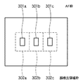
さて、この顔検出処理に要する時間は直接シャッタータイムラグへ影響するため、顔検出処理にかかる時間を低減する必要がある。例えば、図3は3点オートフォーカス(以下AFと略する)を行うカメラのファインダ内の見え方の例を模式的に示した図である。カメラは301a〜301cの3点のAF枠のどこに合焦させるかを判断し、合焦するAF枠を表示する。このような3点AFシステムにおいては画面全体にわたって人物の顔を検出する必要はなく、302a〜302cに示した3つの顔検出領域枠に示されたエリア内でそれぞれ顔検出を行い、顔が判別されたエリアが合焦するようにカメラを制御すればよい。すなわち、AF枠301a〜301cに対応して顔検出領域枠302a〜302cを設定し、これら顔検出領域枠について顔検出を行うことにより、撮像装置の制御(AFやAE等)に対して効果のある顔検出を行うことができる。
Now, since the time required for the face detection process directly affects the shutter time lag, it is necessary to reduce the time required for the face detection process. For example, FIG. 3 is a diagram schematically showing an example of how the camera looks in the viewfinder of a camera that performs three-point autofocus (hereinafter abbreviated as AF). The camera determines where to focus on the three AF frames 301a to 301c, and displays the AF frame to be focused. In such a three-point AF system, it is not necessary to detect a human face over the entire screen. Face detection is performed by performing face detection in the areas indicated by the three face
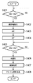
図5は、画像処理部20による顔領域検出処理を説明するフローチャートである。また、図6は画像処理部20による顔領域検出処理のための機能構成を示すブロック図である。以下、画像処理部20による顔領域検出処理の動作を図5及び図6を用いて説明する。
FIG. 5 is a flowchart for explaining face area detection processing by the
システム制御部50の指示により顔検出処理がスタートすると、ステップS501において、エリア設定部601が切り出し領域数と切り出し領域座標を設定する。本実施形態では、図3に示されるように、切り出し領域数は3、切り出し領域座標は顔検出枠302a、302b、302cとなるように設定される。顔検出領域枠は、図6に示すように、例えば予めメモリ52に格納されている。なお、顔検出領域枠は、例えば、枠の左上と右下の座標によって特定される。
When the face detection process is started by an instruction from the
ステップS502において、エリア設定部601は、顔検出枠302aの切り出し座標(例えば、顔検出領域枠302aの右上角(Xs,Ys)と左下角(Xe,Ye)により規定される)を領域切り出し処理部602に渡す。次に、ステップS503において、領域切り出し処理部602は、エリア設定部601より渡された切り出し領域座標に従って領域の切り出しを行う。上記の例では、画像データからまず顔検出領域枠302aの領域が切り出される。切り出された画像データは顔検出処理部603へと送られる。ステップS504において、顔検出処理部603は、領域切り出し処理部602によって切り出された画像データ(顔検出枠301a内の画像データ)について顔検出処理を行なう。ステップS505において、情報格納部604は、顔検出処理部603が検出された顔の数とそれぞれの大きさおよび座標データをメモリ30に格納する。
In step S502, the
次に、ステップS506において、エリア設定部601にて設定されたすべての顔検出枠について顔検出処理を行ったかを判定する。例えば、処理した顔検出枠の数をカウントし、これがステップS501で設定された切り出し領域数と一致するかどうかですべての顔検出枠について顔検出処理を行ったかを判定するようにしてもよい。未処理の顔検出枠があれば処理をステップS502に戻し、未処理の顔検出枠について上述の処理を繰り返す。例えば、エリア設定部601が次の処理対象とすべき顔検出領域枠302bを示す切り出し座標を領域切り出し部602に設定することにより、領域切り出し部602及び顔検出処理部603は顔検出枠302bについて顔検出処理を実行する。
In step S506, it is determined whether face detection processing has been performed for all face detection frames set by the
以上のようにして、図3の顔検出枠302a〜302cの全てについて顔検出処理を終えたならばステップS506より図5に示した画像処理部20の顔検出処理を終了する。こうして、本顔検出処理の終了時には、顔検出枠302a〜302cの全顔検出枠の領域について顔検出処理が行われ、その結果が情報格納部604によりメモリ30に格納される。
As described above, when face detection processing is completed for all of the
なお、上記顔検出処理部603では、顔の位置及び座標と顔の大きさを検出している。顔の位置及び座標の検出方法としては「顔領域抽出に有効な修正HSV表色系の提案」(非特許文献1)、或いは、「静止濃淡情景画像から顔領域を抽出する手法」(非特許文献2)に開示された方法を用いることができる。これらの方法で顔検出および座標位置の検出を行う。或いは、目を検出することにより得られる左目と右目の間隔を用いて顔の大きさや位置の推定を行うこともできる。目の検出には特開平3−17696号公報(特許文献2)、特開平4−255015号公報(特許文献3)、特開平5−300601号公報(特許文献4)、特開平9−251342号公報(特許文献5)の技術を用いることができる。
The face
以上のようにして、ステップS402による顔領域検出が終了すると、ステップS403において、切り出されたエリア(顔検出枠)毎の顔検出情報をもとにAE処理が行われる。以下に顔検出結果を用いたAE処理について説明する。例えば顔検出された領域が図3の顔検出領域枠302bのみであった場合には、顔検出領域枠302bの領域の輝度が適正になるように、絞りとシャッタースピードが決定される。また、顔検出領域枠302aと302bに顔が検出された場合においては、顔検出領域枠302aと302bの領域内の平均輝度が適正になるように絞りとシャッタースピードが決定される。更に、顔検出領域枠302a、302b、302cに顔が検出された場合においては、顔検出領域枠302a、302b、302cの領域の平均輝度が適正になるように絞りとシャッタースピードが決定される。また、何れの顔検出領域枠にも顔が検出されなかった場合には、顔検出領域枠302a、302b、302c内の平均輝度が適正になるように絞りとシャッタースピードが決定される。なお、AE処理自体は、上述したように画像処理部20、システム制御部50及び露光制御部42の協働により実現される。
As described above, when the face area detection in step S402 ends, in step S403, the AE process is performed based on the face detection information for each clipped area (face detection frame). The AE process using the face detection result will be described below. For example, when the face detection area is only the face
以上のようにして、AE処理が終了すると、処理はステップS404へ進み、AF処理が行われる。以下に顔検出結果を用いたAF処理について説明する。図1の測距制御部44により、撮像レンズ10の中にある、フォーカスレンズ位置を一定量動かしながら順に撮像をおこなう。そして、撮像された画像データのうちの、顔が検出された顔検出領域枠内の画像データからバンドパスフィルター処理によりAF信号を作成する。作成されたAF信号が一番大きくなるフォーカスレンズ位置をもとめて、そのフォーカスレンズ位置を合焦点位置とする。
As described above, when the AE process ends, the process proceeds to step S404, and the AF process is performed. The AF process using the face detection result will be described below. The distance
例えば顔検出された領域が顔検出領域枠302bのみであった場合には、顔検出領域枠302b内の画像データを用いてAF信号が作成され、AF信号の最も大きいフォーカスレンズ位置が求められる。また、顔検出領域枠302aと302bに顔が検出された場合においては、顔検出領域枠302aと302bをあわせた領域の画像データを用いてAF信号の最も大きいフォーカスレンズ位置が求められる。更に、顔検出領域枠302a、302b、302cに顔が検出された場合においては、顔検出領域枠302a、302b、302cをあわせた領域の画像データを用いて、AF信号の最も大きいフォーカスレンズ位置が求められる。なお、顔領域検処理により顔が検出されなかった場合には、顔検出領域枠302a、302b、302cをあわせた領域の画像データを用いてAF信号を作成し、最もAF信号の大きいフォーカスレンズ位置が求められる。
For example, when the face detection area is only the face
AF処理が終了するとSW2がONするのを待機する状態になる(ステップS405)。ユーザによりシャッターボタン303が押しこまれ、シャッタースイッチ64がON状態となると、システム制御部50にSW2のON信号が入力される。SW2がONとなると、処理はステップS406へ進み、システム制御部50は、ステップS403、S404で求めた絞り、シャッタースピードおよび、フォーカスレンズ位置にて本露光を行う。本露光によって撮像素子14より出力されたアナログ信号はA/D変換器16によりデジタル信号へと変換され、画像処理部20へ送られる。ステップS407において、画像処理部20は、デジタル信号をYUV信号へ変換し、更に、JPEGフォーマットへと変換し、メモリ30に格納する。そして、ステップS408において、このJPEGフォーマット変換されたデータを、画像ファイルとして記録部202(或いは212)に記録する。
When the AF process ends, the system waits for SW2 to turn on (step S405). When the user presses the shutter button 303 and the shutter switch 64 is turned on, an ON signal of SW2 is input to the
以上説明したように、第1実施形態によれば、撮像素子から取り込まれる画像の全体について顔検出処理を行うのではなく、顔検出領域枠という限定された領域について顔検出処理が行われる。そのため、顔検出処理時間が短縮され、シャッタータイムラグを低減することができる。 As described above, according to the first embodiment, face detection processing is performed on a limited region called a face detection region frame, rather than performing face detection processing on the entire image captured from the image sensor. Therefore, the face detection processing time is shortened and the shutter time lag can be reduced.
なお、複数の顔検出領域枠のうち、顔検出処理を行なうべき所望の一つ又は複数の顔検出領域枠を前もってユーザが選択可能にしてもよい。この場合、ステップS401では、選択された顔検出領域枠のみに対して顔領域検出処理を行うことになる。或いは、ユーザによるAF枠の選択が可能な撮像装置の場合、選択されたAF枠に対応する顔検出領域枠を用いて顔検出を行うようにしてもよい。その場合、エリア設定部601が設定する領域数、切り出し領域座標は、ユーザによって選択された顔検出領域枠、或いは、AF枠の選択に従って選択された顔検出領域枠に関するものとなる。
It should be noted that the user may be able to select in advance one or more desired face detection area frames to be subjected to face detection processing from among the plurality of face detection area frames. In this case, in step S401, the face area detection process is performed only on the selected face detection area frame. Alternatively, in the case of an imaging apparatus that allows the user to select an AF frame, face detection may be performed using a face detection area frame corresponding to the selected AF frame. In this case, the number of areas and the cut-out area coordinates set by the
<第2実施形態>
第1実施形態では、図4のフローチャートに示したようにシャッタースイッチSW1がONした後、顔検出、AE処理、AF処理が終了しないと、シャッタースイッチSW2のON検出に移行することができない。そのため、シャッターレリーズタイムラグが大きくなるという課題が生じることが考えられる。そこで、第2実施形態では、更にシャッターレリーズタイムラグを短縮することを可能とする。
Second Embodiment
In the first embodiment, as shown in the flowchart of FIG. 4, after face switch, AE process, and AF process are not completed after the shutter switch SW1 is turned on, it is not possible to shift to ON detection of the shutter switch SW2. For this reason, a problem that the shutter release time lag increases may be considered. Therefore, in the second embodiment, it is possible to further reduce the shutter release time lag.
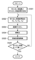
撮像装置の構成等は第1実施形態と同様であるため、ここでは説明を省略する。以下、主として第1実施形態と同異なる部分について説明を行う。図7は第2実施形態の画像処理部20による顔領域検出処理を説明するフローチャートである。また、図8は第2実施形態の画像処理部20による顔領域検出処理のための機能構成を示すブロック図である。なお、図7において図5と同様の処理には同一のステップ番号を付してある。また、図8において図6に示される構成と同様の機能ブロックには同一の参照番号を付してある。また、撮影動作の処理の流れは図4のフローチャートのとおりである。
Since the configuration and the like of the imaging device are the same as those in the first embodiment, description thereof is omitted here. Hereinafter, mainly the same parts as in the first embodiment will be described. FIG. 7 is a flowchart for explaining face area detection processing by the
シャッターボタン303が半押し状態となり、信号SW1がONになると、ステップS401からステップS402へ進み、顔領域検出処理が行われる。第2実施形態では、この顔検出処理が図7のフローチャートに示すものとなる。 When the shutter button 303 is pressed halfway and the signal SW1 is turned on, the process proceeds from step S401 to step S402, and face area detection processing is performed. In the second embodiment, this face detection process is shown in the flowchart of FIG.
ステップS501において、エリア設定部802は切り出し領域数と切り出し領域座標を設定する。第2実施形態においても、図3に示されるように、切り出し領域数は3、切り出し領域座標は顔検出枠302a、302b、302cとなるように設定されるものとする。
In step S501, the
次に、ステップS701において、優先度設定部801(図8)は、切り出し領域の優先度を設定する。顔検出領域枠と設定された優先度を示すデータの例を図8(テーブル810)に示す。ここでは、顔検出領域枠302b、302a、302cの順に優先度が設定されるものとして説明する。なお、優先度設定部801は、十字キーなどの操作に応じて、顔検出領域枠に所望の優先順位を設定する。従って、優先順位の設定状態は書き換えが可能なメモリ30に格納される。それぞれの領域の領域の優先度が設定されると、ステップS702において、エリア設定部802は、設定された優先度の高い順に、領域切り出し処理部602に対して切り出し領域枠の座標を設定する。すなわち、本例では、まず、顔検出領域枠302bの領域が画像データから切り出される。そして、この切り出された画像データが顔検出部603へ送られ、切り出された画像データ内の顔の数とそれぞれの大きさおよび座標データが出力される(ステップS503、S504)。顔検出処理部603にて出力されたデータは情報格納部604により顔検出情報としてメモリ30に格納される(ステップS505)。
Next, in step S701, the priority setting unit 801 (FIG. 8) sets the priority of the cutout area. An example of data indicating the face detection area frame and the set priority is shown in FIG. 8 (table 810). Here, description will be made assuming that the priority is set in the order of the face detection area frames 302b, 302a, and 302c. The
次に、ステップS703において、上記ステップS702、S503〜S505の処理の間に信号SW2がONになったかどうかを判定する。ここで、信号SW2がONになっていれば、直ちに顔検出処理を終了する。一方、信号SW2がONになっていなければ、ステップS506において、エリア設定部802にて設定された領域すべてについて顔検出処理を行ったかを判定する。ここでは、まだ顔検出領域枠302a、302cの顔検出が終了していないため、処理をステップS702に戻す。そして、エリア設定部802は、次の優先度の領域を示す切り出し領域座標を領域切り出し処理部602に設定する。こうして、顔検出領域枠302aに対する顔検出が行われる。このように顔検出領域枠302a、302cの顔検出処理が終了し、情報格納部604により各領域の顔検出情報がメモリ30に格納されると、ステップS506により顔領域検出処理が終了する。
Next, in step S703, it is determined whether or not the signal SW2 has been turned ON during the processing in steps S702 and S503 to S505. If the signal SW2 is ON, the face detection process is immediately terminated. On the other hand, if the signal SW2 is not ON, it is determined in step S506 whether face detection processing has been performed for all the areas set by the
なお、全ての顔検出領域枠について顔検出処理が行われる前に信号SW2がONとなった場合、顔検出が行われなかった領域は、顔が検出されなかったものとして取り扱われる。図4に戻り、ステップS402の顔領域検出処理が終了すると、顔領域検出情報を用いたAE処理およびAF処理が行われる。図4のステップS403以降の動作は第1実施形態と全く同じであるためここでは説明を省略する。 If the signal SW2 is turned on before face detection processing is performed for all face detection area frames, the area where face detection has not been performed is handled as if no face was detected. Returning to FIG. 4, when the face area detection processing in step S <b> 402 ends, AE processing and AF processing using the face area detection information are performed. Since the operation after step S403 in FIG. 4 is exactly the same as in the first embodiment, the description thereof is omitted here.
以上のように、第2実施形態によれば、優先順位の高い顔領域検出枠の順に顔検出処理が行われていく。そして、その途中で、シャッターボタン303が全押し状態となり、信号SW2がONすると、顔検出処理中の顔領域検出枠について処理を終えた後、直ちに顔領域検出を終了する。信号SW2のONにより顔検出処理が打ち切られるので、シャッターレリーズタイムラグを低減することができる。また、優先順位に従って顔検出処理対象となる顔検出領域枠が選択されて顔検出処理が行われるので、未処理の顔検出領域枠が残ったとしても、効果的な顔領域検出結果が得られることになる。また、半押し状態(信号SW1のON状態)の継続時間により、顔領領域の検出数を調整でき、AE,AFの精度を調整できる。 As described above, according to the second embodiment, face detection processing is performed in the order of face area detection frames with higher priority. In the middle of this, when the shutter button 303 is fully pressed and the signal SW2 is turned on, the face area detection immediately ends after the process for the face area detection frame during the face detection process is completed. Since the face detection process is terminated when the signal SW2 is turned on, the shutter release time lag can be reduced. In addition, since the face detection area frame to be face detection processing is selected according to the priority order and the face detection process is performed, an effective face area detection result can be obtained even if an unprocessed face detection area frame remains. It will be. In addition, the number of detected face areas can be adjusted by adjusting the half-pressed state (the signal SW1 is ON), and the accuracy of AE and AF can be adjusted.
なお、顔検出領域枠の優先順位については、固定であってもよいし、ユーザが所望に順位を設定できるようにしてもよい。優先順位が固定の場合は、メモリ52に図8に示したようなテーブル810を保持すればよい。また、顔検出領域が選択的に用いられる場合(ユーザが選択した顔検出領域枠、或いはユーザが選択したAF枠に対応する顔検出領域枠が用いられる場合)にも、優先順位を設定する本実施形態が適用可能であることは明らかである。なお、優先順位が固定であって、顔検出領域枠が選択的に用いられる場合は、その優先順位の相対的な順位関係が保たれるように、選択された顔検出領域に優先順位を設定すればよい。 The priority order of the face detection area frames may be fixed, or the user may set the order as desired. When the priority order is fixed, a table 810 as shown in FIG. In addition, when the face detection area is selectively used (when the face detection area frame selected by the user or the face detection area frame corresponding to the AF frame selected by the user is used), this book for setting the priority order It is clear that the embodiments are applicable. When the priority order is fixed and the face detection area frame is selectively used, the priority order is set for the selected face detection area so that the relative order relationship of the priority order is maintained. do it.
また、上記第2実施形態においては、図7のフローチャートに示したように、信号SW1のON後、すぐに信号SW2がONになっても必ず優先順位が1番目の領域に関しては顔検出処理が行われる。しかしながら、このような処理に限られるものではなく、例えば、図10のように信号SW2がONになっているかの判定を画像切り出しおよび顔検出を行う前に実行する(ステップS702)ようにしてもよい。この場合、信号SW2がONになるタイミングによっては顔検出処理を全く行わないうちに顔領域検出処理が終了することになる。 In the second embodiment, as shown in the flowchart of FIG. 7, even if the signal SW2 is turned on immediately after the signal SW1 is turned on, the face detection process is always performed for the first priority area. Done. However, the present invention is not limited to such processing. For example, as shown in FIG. 10, whether the signal SW <b> 2 is ON is determined before image cutout and face detection (step S <b> 702). Good. In this case, depending on the timing at which the signal SW2 is turned ON, the face area detection process ends before the face detection process is performed at all.
<第3実施形態>
第2実施形態では、シャッタースイッチ64による信号SW2により顔領域検出処理を終了させる構成を説明した。第3実施形態では、複数の顔検出領域枠について、優先順位の高い順に顔検出処理を行ない、顔が検出された場合に顔領域検出処理(ステップS402)を終了する。
<Third Embodiment>
In the second embodiment, the configuration in which the face area detection process is terminated by the signal SW2 from the shutter switch 64 has been described. In the third embodiment, face detection processing is performed in descending order of priority for a plurality of face detection region frames, and the face region detection processing (step S402) ends when a face is detected.
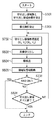
撮像装置の構成等は第1実施形態と同様であるため、ここでは説明を省略する。以下、主として第1実施形態と同異なる部分について説明を行う。図10は第3実施形態の画像処理部20による顔領域検出処理を説明するフローチャートである。なお、撮像装置の動作シーケンスは第1実施形態(図4)と同様であり、画像処理部20における顔検出処理の機能構成は第2実施形態(図8)と同様である。
Since the configuration and the like of the imaging device are the same as those in the first embodiment, description thereof is omitted here. Hereinafter, mainly the same parts as in the first embodiment will be described. FIG. 10 is a flowchart illustrating face area detection processing by the
信号SW1がONとなるとステップS402による顔領域検出処理が行われる。この顔検出処理の動作を図10のフローチャートを用いて説明する。 When the signal SW1 is turned on, face area detection processing in step S402 is performed. The operation of this face detection process will be described using the flowchart of FIG.
ステップS501において、エリア設定部802が切り出し領域数と切り出し領域座標を設定する。第3実施形態においても、図3に示されるように、切り出し領域数は3、切り出し領域座標は顔検出枠302a、302b、302cとなるように設定されるものとする。
In step S501, the
次に、ステップS701において、優先度設定部801(図8)は切り出し領域の優先度を設定する。ここでは、顔検出領域枠302b、302a、302cの順に優先度が設定されるものとして説明する。それぞれの領域の領域の優先度が設定されると、ステップS702において、エリア設定部802は、設定された優先度の高い順に、領域切り出し処理部602に対して切り出し領域枠の座標を設定する。従って、本例では、まず、顔検出領域枠302bの領域が画像データから切り出される。そして、この切り出された画像データが顔検出部603へ送られ、切り出された画像データ内の顔の数とそれぞれの大きさおよび座標データが出力される(ステップS503、S504)。顔検出処理部603にて出力されたデータは情報格納部604により顔検出情報としてメモリ30に格納される(ステップS505)。
Next, in step S701, the priority setting unit 801 (FIG. 8) sets the priority of the clip region. Here, description will be made assuming that the priority is set in the order of the face detection area frames 302b, 302a, and 302c. When the priority of each area is set, in step S702, the
次に、ステップS1001において、上記ステップS702、S503〜S505の処理によって顔が検出されたか否かを判定する。ここで、顔が検出されていれば、直ちに顔検出処理を終了する。一方、ステップS1001で顔が検出されていないと判定された場合は、ステップS506において、エリア設定部802にて設定された領域すべてについて顔検出処理を行ったかを判定する。ここでは、まだ顔検出領域枠302a、302cの顔検出が終了していないため、処理をステップS702に戻す。そして、エリア設定部802は、次の優先度の領域を示す切り出し領域座標を領域切り出し処理部602に設定する。こうして、顔検出領域枠302aに対する顔検出が行われる。このように顔検出領域枠302a、302cの顔検出処理が終了し、情報格納部604により各領域の顔検出情報がメモリ30に格納されると、ステップS506により顔領域検出処理が終了する。
Next, in step S1001, it is determined whether or not a face has been detected by the processing in steps S702 and S503 to S505. Here, if a face is detected, the face detection process is immediately terminated. On the other hand, if it is determined in step S1001 that no face has been detected, it is determined in step S506 whether face detection processing has been performed for all the areas set by the
図4に戻り、ステップS402の顔領域検出処理が終了すると、顔領域検出情報を用いたAE処理およびAF処理が行われる。図4のステップS403以降の動作は第1実施形態と全く同じであるためここでは説明を省略する。 Returning to FIG. 4, when the face area detection processing in step S <b> 402 ends, AE processing and AF processing using the face area detection information are performed. Since the operation after step S403 in FIG. 4 is exactly the same as in the first embodiment, the description thereof is omitted here.
以上説明したように、第3実施形態によれば、顔が検出された時点で顔領域検出処理を終えるので、シャッターレリーズタイムラグを低減することができる。また、優先順位に従って顔検出処理対象となる顔検出領域枠が選択されて顔検出処理が行われるので、顔が検出された時点で顔検出処理を終了しても、撮影に適した顔検出が行われていることになる。すなわち、必要最低限の顔領域検出を行って撮影動作に移行するので、レリーズタイムラグの低減と適切な顔領域の検出を両立させることができる。 As described above, according to the third embodiment, since the face area detection process is completed when a face is detected, the shutter release time lag can be reduced. In addition, since the face detection region frame to be face detection processing target is selected according to the priority order and the face detection processing is performed, even if the face detection processing is terminated when the face is detected, face detection suitable for shooting can be performed. Will be done. In other words, since the minimum necessary face area detection is performed and the shooting operation is performed, it is possible to achieve both reduction of the release time lag and detection of an appropriate face area.
<他の実施形態>
上記第1〜第3実施形態においては、図3に示されるように画像を3つの領域に分割して顔検出する例を示して説明した。しかしながら、顔検出領域枠の設定はこれに限られるものでなく、1つ以上の領域が設定されていれば幾つでも良い。また、図11に示される様に顔検出領域枠が他の顔検出領域枠とオーバーラップするように設定されてもよい。
<Other embodiments>
In the first to third embodiments, the example in which the face is detected by dividing the image into three regions as shown in FIG. 3 has been described. However, the setting of the face detection area frame is not limited to this, and may be any number as long as one or more areas are set. Further, as shown in FIG. 11, the face detection area frame may be set to overlap with other face detection area frames.
以上説明したように、上記実施形態によれば、顔検出を行い最適な撮影条件を求めて撮影するカメラにおいて、画面の必要領域部分のみについて顔検出を行うので、顔検出処理時間が短縮され、レリーズタイムラグを低減することが可能となる。またユーザのシャッタースイッチ操作により顔検出を中断すること、また必要最低限の顔領域検出を行うことでさらにレリーズタイムラグを低減させることが可能となる。 As described above, according to the above-described embodiment, in the camera that performs face detection and obtains an optimal shooting condition and performs shooting, face detection is performed only for a necessary area portion of the screen. The release time lag can be reduced. In addition, it is possible to further reduce the release time lag by interrupting the face detection by the user's shutter switch operation and performing the minimum necessary face area detection.
Claims (10)
画像中における複数の部分領域を示す領域データを保持する保持手段と、
前記保持手段に保持された領域データによって示される部分領域内の画像データから顔領域を検出する検出手段と、
前記検出手段で検出された顔領域内の画像データに基づいて当該撮像装置の制御を行う制御手段とを備えることを特徴とする撮像装置。 An imaging device that obtains image data by converting an output of an imaging device that converts incident light into an electrical signal into a digital value,
Holding means for holding area data indicating a plurality of partial areas in the image;
Detecting means for detecting a face area from image data in a partial area indicated by the area data held in the holding means;
An imaging apparatus comprising: control means for controlling the imaging apparatus based on image data in the face area detected by the detection means.
前記検出手段は、前記選択手段で選択された部分領域の全てについて顔領域の検出を実行することを特徴とする請求項1に記載の撮像装置。 A selection means for selecting a desired partial area from the plurality of partial areas;
The imaging apparatus according to claim 1, wherein the detection unit performs face region detection for all of the partial regions selected by the selection unit.
前記検出手段は、前記優先順位の高い順に部分領域を選択して顔領域の検出を実行し、所定の操作信号の入力に応じて顔領域の検出を終了することを特徴とする請求項1に記載の撮像装置。 Priorities are set for the plurality of partial areas,
2. The detection unit according to claim 1, wherein the detection unit selects a partial area in descending order of priority, executes face area detection, and ends detection of the face area in response to an input of a predetermined operation signal. The imaging device described.
前記検出手段は、前記優先順位の高い順に部分領域を選択して顔領域の検出を実行し、顔領域が検出されたことに応じて顔領域の検出を終了することを特徴とする請求項1に記載の撮像装置。 Priorities are set for the plurality of partial areas,
2. The detection unit according to claim 1, wherein the detection unit selects a partial region in descending order of priority, executes detection of a facial region, and terminates detection of the facial region when the facial region is detected. The imaging device described in 1.
前記複数の部分領域は前記複数のオートフォーカス枠に対応して設定されていることを特徴とする請求項1乃至6のいずれかに記載の撮像装置。 The imaging apparatus has a plurality of autofocus frames,
The imaging apparatus according to claim 1, wherein the plurality of partial areas are set corresponding to the plurality of autofocus frames.
画像中における複数の部分領域を示す領域データを保持するメモリをアクセスして、領域データを取得し、取得された領域データによって示される部分領域内の画像データから顔領域を検出する検出工程と、
前記検出工程で検出された顔領域内の画像データに基づいて当該撮像装置の制御を行う制御工程とを備えることを特徴とする撮像装置の制御方法。 A method for controlling an imaging apparatus that obtains image data by converting an output of an imaging element that converts incident light into an electrical signal into a digital value,
A detection step of accessing a memory holding area data indicating a plurality of partial areas in an image, acquiring the area data, and detecting a face area from the image data in the partial area indicated by the acquired area data;
A control step of controlling the imaging device based on image data in the face area detected in the detection step.
Priority Applications (1)
| Application Number | Priority Date | Filing Date | Title |
|---|---|---|---|
| JP2005265936A JP2007081732A (en) | 2005-09-13 | 2005-09-13 | Imaging apparatus |
Applications Claiming Priority (1)
| Application Number | Priority Date | Filing Date | Title |
|---|---|---|---|
| JP2005265936A JP2007081732A (en) | 2005-09-13 | 2005-09-13 | Imaging apparatus |
Publications (2)
| Publication Number | Publication Date |
|---|---|
| JP2007081732A true JP2007081732A (en) | 2007-03-29 |
| JP2007081732A5 JP2007081732A5 (en) | 2008-10-16 |
Family
ID=37941580
Family Applications (1)
| Application Number | Title | Priority Date | Filing Date |
|---|---|---|---|
| JP2005265936A Pending JP2007081732A (en) | 2005-09-13 | 2005-09-13 | Imaging apparatus |
Country Status (1)
| Country | Link |
|---|---|
| JP (1) | JP2007081732A (en) |
Cited By (8)
| Publication number | Priority date | Publication date | Assignee | Title |
|---|---|---|---|---|
| JP2008294788A (en) * | 2007-05-25 | 2008-12-04 | Sharp Corp | Imaging apparatus with multi-step zoom function, for imaging multiple areas |
| JP2009020163A (en) * | 2007-07-10 | 2009-01-29 | Casio Comput Co Ltd | Imaging apparatus and program therefor |
| JP2009141538A (en) * | 2007-12-05 | 2009-06-25 | Casio Comput Co Ltd | Imaging apparatus, image playback device, and program for them |
| JP2009145622A (en) * | 2007-12-14 | 2009-07-02 | Sanyo Electric Co Ltd | Electronic camera |
| JP2010050950A (en) * | 2008-07-23 | 2010-03-04 | Victor Co Of Japan Ltd | Imaging apparatus |
| JP2010541398A (en) * | 2007-09-24 | 2010-12-24 | ジェスチャー テック,インコーポレイテッド | Enhanced interface for voice and video communication |
| US8823864B2 (en) | 2007-06-28 | 2014-09-02 | Sony Corporation | Image capturing apparatus and associated methodology for auto-focus and facial detection |
| JP2022043749A (en) * | 2020-09-04 | 2022-03-16 | 株式会社セルシス | Information processing device, information processing system, information processing method, and program |
Citations (1)
| Publication number | Priority date | Publication date | Assignee | Title |
|---|---|---|---|---|
| JP2001264621A (en) * | 2000-03-15 | 2001-09-26 | Olympus Optical Co Ltd | Range-finding device |
-
2005
- 2005-09-13 JP JP2005265936A patent/JP2007081732A/en active Pending
Patent Citations (1)
| Publication number | Priority date | Publication date | Assignee | Title |
|---|---|---|---|---|
| JP2001264621A (en) * | 2000-03-15 | 2001-09-26 | Olympus Optical Co Ltd | Range-finding device |
Cited By (9)
| Publication number | Priority date | Publication date | Assignee | Title |
|---|---|---|---|---|
| JP2008294788A (en) * | 2007-05-25 | 2008-12-04 | Sharp Corp | Imaging apparatus with multi-step zoom function, for imaging multiple areas |
| US8823864B2 (en) | 2007-06-28 | 2014-09-02 | Sony Corporation | Image capturing apparatus and associated methodology for auto-focus and facial detection |
| JP2009020163A (en) * | 2007-07-10 | 2009-01-29 | Casio Comput Co Ltd | Imaging apparatus and program therefor |
| JP2010541398A (en) * | 2007-09-24 | 2010-12-24 | ジェスチャー テック,インコーポレイテッド | Enhanced interface for voice and video communication |
| US8830292B2 (en) | 2007-09-24 | 2014-09-09 | Qualcomm Incorporated | Enhanced interface for voice and video communications |
| JP2009141538A (en) * | 2007-12-05 | 2009-06-25 | Casio Comput Co Ltd | Imaging apparatus, image playback device, and program for them |
| JP2009145622A (en) * | 2007-12-14 | 2009-07-02 | Sanyo Electric Co Ltd | Electronic camera |
| JP2010050950A (en) * | 2008-07-23 | 2010-03-04 | Victor Co Of Japan Ltd | Imaging apparatus |
| JP2022043749A (en) * | 2020-09-04 | 2022-03-16 | 株式会社セルシス | Information processing device, information processing system, information processing method, and program |
Similar Documents
| Publication | Publication Date | Title |
|---|---|---|
| JP4448039B2 (en) | Imaging apparatus and control method thereof | |
| JP4481842B2 (en) | Imaging apparatus and control method thereof | |
| JP4035543B2 (en) | Imaging device | |
| JP4574459B2 (en) | Image capturing apparatus, control method therefor, program, and storage medium | |
| JP5424732B2 (en) | Imaging apparatus, control method thereof, and program | |
| JP5366584B2 (en) | Imaging apparatus, image processing method, and program | |
| JP2009177328A (en) | Imaging device | |
| JP4891270B2 (en) | Image editing apparatus, image editing method and program | |
| JP2006323374A (en) | Imaging apparatus and control method therefor | |
| JP2007081732A (en) | Imaging apparatus | |
| JP5207918B2 (en) | Image processing apparatus, imaging apparatus, and image processing method | |
| JP2009060291A (en) | Image processing apparatus, image processing method and program | |
| JP2009038750A (en) | Image processing apparatus, method, and program | |
| JP2015097322A (en) | Imaging apparatus, control method of the same, program, and storage medium | |
| JP2007036587A (en) | Imaging apparatus and its control method | |
| JP2009177358A (en) | Image processor, image processing method, and program | |
| JP5116494B2 (en) | Imaging device | |
| JP4401974B2 (en) | Imaging apparatus and control method thereof | |
| JP2006039203A (en) | Imaging apparatus, and its control method | |
| JP2008060844A (en) | Image processor and image processing method | |
| JP2005134532A (en) | Imaging apparatus, display control method and display control program | |
| JP4667251B2 (en) | Imaging apparatus and white balance control method | |
| JP2009043169A (en) | Image processor, and image processing method and program | |
| JP2005110128A (en) | Imaging apparatus and imaging control method | |
| JP2010093392A (en) | Imaging apparatus, control method therefor, and program |
Legal Events
| Date | Code | Title | Description |
|---|---|---|---|
| A521 | Request for written amendment filed |
Free format text: JAPANESE INTERMEDIATE CODE: A523 Effective date: 20080901 |
|
| A621 | Written request for application examination |
Free format text: JAPANESE INTERMEDIATE CODE: A621 Effective date: 20080901 |
|
| A977 | Report on retrieval |
Free format text: JAPANESE INTERMEDIATE CODE: A971007 Effective date: 20101021 |
|
| A131 | Notification of reasons for refusal |
Free format text: JAPANESE INTERMEDIATE CODE: A131 Effective date: 20101029 |
|
| A02 | Decision of refusal |
Free format text: JAPANESE INTERMEDIATE CODE: A02 Effective date: 20110325 |