JP4574162B2 - Data storage - Google Patents
Data storage Download PDFInfo
- Publication number
- JP4574162B2 JP4574162B2 JP2003391064A JP2003391064A JP4574162B2 JP 4574162 B2 JP4574162 B2 JP 4574162B2 JP 2003391064 A JP2003391064 A JP 2003391064A JP 2003391064 A JP2003391064 A JP 2003391064A JP 4574162 B2 JP4574162 B2 JP 4574162B2
- Authority
- JP
- Japan
- Prior art keywords
- data
- storage device
- information
- data storage
- area
- Prior art date
- Legal status (The legal status is an assumption and is not a legal conclusion. Google has not performed a legal analysis and makes no representation as to the accuracy of the status listed.)
- Expired - Fee Related
Links
Images


Classifications
-
- G—PHYSICS
- G06—COMPUTING; CALCULATING OR COUNTING
- G06F—ELECTRIC DIGITAL DATA PROCESSING
- G06F21/00—Security arrangements for protecting computers, components thereof, programs or data against unauthorised activity
- G06F21/70—Protecting specific internal or peripheral components, in which the protection of a component leads to protection of the entire computer
- G06F21/78—Protecting specific internal or peripheral components, in which the protection of a component leads to protection of the entire computer to assure secure storage of data
- G06F21/79—Protecting specific internal or peripheral components, in which the protection of a component leads to protection of the entire computer to assure secure storage of data in semiconductor storage media, e.g. directly-addressable memories
-
- G—PHYSICS
- G06—COMPUTING; CALCULATING OR COUNTING
- G06F—ELECTRIC DIGITAL DATA PROCESSING
- G06F21/00—Security arrangements for protecting computers, components thereof, programs or data against unauthorised activity
- G06F21/70—Protecting specific internal or peripheral components, in which the protection of a component leads to protection of the entire computer
- G06F21/78—Protecting specific internal or peripheral components, in which the protection of a component leads to protection of the entire computer to assure secure storage of data
-
- G—PHYSICS
- G06—COMPUTING; CALCULATING OR COUNTING
- G06F—ELECTRIC DIGITAL DATA PROCESSING
- G06F21/00—Security arrangements for protecting computers, components thereof, programs or data against unauthorised activity
- G06F21/70—Protecting specific internal or peripheral components, in which the protection of a component leads to protection of the entire computer
- G06F21/88—Detecting or preventing theft or loss
-
- H—ELECTRICITY
- H04—ELECTRIC COMMUNICATION TECHNIQUE
- H04N—PICTORIAL COMMUNICATION, e.g. TELEVISION
- H04N1/00—Scanning, transmission or reproduction of documents or the like, e.g. facsimile transmission; Details thereof
- H04N1/44—Secrecy systems
- H04N1/4406—Restricting access, e.g. according to user identity
- H04N1/4426—Restricting access, e.g. according to user identity involving separate means, e.g. a server, a magnetic card
-
- H—ELECTRICITY
- H04—ELECTRIC COMMUNICATION TECHNIQUE
- H04N—PICTORIAL COMMUNICATION, e.g. TELEVISION
- H04N1/00—Scanning, transmission or reproduction of documents or the like, e.g. facsimile transmission; Details thereof
- H04N1/44—Secrecy systems
- H04N1/4406—Restricting access, e.g. according to user identity
- H04N1/444—Restricting access, e.g. according to user identity to a particular document or image or part thereof
-
- G—PHYSICS
- G06—COMPUTING; CALCULATING OR COUNTING
- G06F—ELECTRIC DIGITAL DATA PROCESSING
- G06F2221/00—Indexing scheme relating to security arrangements for protecting computers, components thereof, programs or data against unauthorised activity
- G06F2221/21—Indexing scheme relating to G06F21/00 and subgroups addressing additional information or applications relating to security arrangements for protecting computers, components thereof, programs or data against unauthorised activity
- G06F2221/2111—Location-sensitive, e.g. geographical location, GPS
-
- G—PHYSICS
- G06—COMPUTING; CALCULATING OR COUNTING
- G06F—ELECTRIC DIGITAL DATA PROCESSING
- G06F2221/00—Indexing scheme relating to security arrangements for protecting computers, components thereof, programs or data against unauthorised activity
- G06F2221/21—Indexing scheme relating to G06F21/00 and subgroups addressing additional information or applications relating to security arrangements for protecting computers, components thereof, programs or data against unauthorised activity
- G06F2221/2143—Clearing memory, e.g. to prevent the data from being stolen
-
- H—ELECTRICITY
- H04—ELECTRIC COMMUNICATION TECHNIQUE
- H04N—PICTORIAL COMMUNICATION, e.g. TELEVISION
- H04N1/00—Scanning, transmission or reproduction of documents or the like, e.g. facsimile transmission; Details thereof
- H04N1/00127—Connection or combination of a still picture apparatus with another apparatus, e.g. for storage, processing or transmission of still picture signals or of information associated with a still picture
- H04N1/00347—Connection or combination of a still picture apparatus with another apparatus, e.g. for storage, processing or transmission of still picture signals or of information associated with a still picture with another still picture apparatus, e.g. hybrid still picture apparatus
-
- H—ELECTRICITY
- H04—ELECTRIC COMMUNICATION TECHNIQUE
- H04N—PICTORIAL COMMUNICATION, e.g. TELEVISION
- H04N2201/00—Indexing scheme relating to scanning, transmission or reproduction of documents or the like, and to details thereof
- H04N2201/0077—Types of the still picture apparatus
- H04N2201/0087—Image storage device
-
- H—ELECTRICITY
- H04—ELECTRIC COMMUNICATION TECHNIQUE
- H04N—PICTORIAL COMMUNICATION, e.g. TELEVISION
- H04N2201/00—Indexing scheme relating to scanning, transmission or reproduction of documents or the like, and to details thereof
- H04N2201/0077—Types of the still picture apparatus
- H04N2201/0094—Multifunctional device, i.e. a device capable of all of reading, reproducing, copying, facsimile transception, file transception
Description
本発明は、データを記憶するデータ記憶装置に関するものである。 The present invention relates to a data storage device for storing data.
近年、機器の位置情報に基づき、機器に格納されるデータへのアクセス制御を行う技術が開発されている。例えばコンピュータ内部に記憶された自宅で作成した特定ファイルに関して、コンピュータの位置(例えばGPS(Global Positioning System)機能を利用して得る)が自宅以外の場合は、その特定のファイル(例えば日記のファイル)に対してアクセスできなくするという技術である。
また、同様の技術として、半導体製造装置の設置場所の緯度経度情報と、リモートアクセスを許可すべきユーザ装置の設置場所の緯度経度情報とを比較・照合して、不正な設置場所データであると判断した場合にはリモートアクセスを切断するという技術が開示されている(例えば、特許文献1参照。)。
In recent years, a technique for controlling access to data stored in a device based on the position information of the device has been developed. For example, regarding a specific file created at home stored in the computer, if the location of the computer (for example, obtained using the GPS (Global Positioning System) function) is other than home, the specific file (for example, a diary file) It is a technology that makes it inaccessible.
In addition, as a similar technique, the latitude / longitude information of the installation location of the semiconductor manufacturing apparatus is compared with the latitude / longitude information of the installation location of the user device that should be permitted remote access, and it is illegal installation location data. A technique of disconnecting remote access when it is determined is disclosed (for example, see Patent Document 1).
また、画像データが格納されている画像保管装置を示す特定情報を管理し、外部装置より画像データの要求があった場合に、該格納されている特定情報に基づいて該画像データが格納されている画像保管装置を特定することにより、画像データの保管場所の変更などが、利用者の利便を損なうこと無く、自由かつ簡便に行えるようにするという技術が開示されている(例えば、特許文献2参照。)。
また、近年、ハードディスクをはじめとする外部記憶装置が小型・大容量になり、大量のデータを外部記憶装置に格納して任意の場所に持ち出し/移動がより容易になってきている。また、例えば社内LANなどのネットワークに接続された複合機などの各種OA(Office Automation)機器が、処理データを記憶するハードディスクを内蔵したり、ネットワークに接続された外部記憶装置を利用したりする技術が開発されている。
Also, it manages specific information indicating the image storage device in which the image data is stored. When there is a request for image data from an external device, the image data is stored based on the stored specific information. A technique has been disclosed in which an image storage device is specified so that image data storage location can be changed freely and easily without impairing the convenience of the user (for example, Patent Document 2). reference.).
In recent years, external storage devices such as hard disks have become smaller and larger in capacity, and a large amount of data has been stored in the external storage device and can be taken out / moved to any location more easily. In addition, for example, various OA (Office Automation) devices such as MFPs connected to a network such as an in-house LAN have a built-in hard disk for storing processing data or use an external storage device connected to the network. Has been developed.
しかしながら、小型・大容量化の負の側面として機密データを管理する場所に設置された外部記憶装置(データ記憶装置)を、悪意のある者が外部に持ち出すことによるデータ漏洩が起こるかもしれないという問題がある。そして、この問題に対処する技術の向上の要望がより切実なものになってきている。
また、ネットワークに接続された各OA機器(データ処理装置)にて管理すべきデータが分散して保存/処理されると、データ容量の増大とともにデータの管理がより複雑かつ困難になってしまうという問題がある。
However, as a negative aspect of downsizing and increasing capacity, data leakage may occur when a malicious person takes out an external storage device (data storage device) installed in a place where confidential data is managed. There's a problem. And the demand for improving the technology to cope with this problem has become more urgent.
In addition, if data to be managed is distributed and stored / processed by each OA device (data processing device) connected to the network, data management becomes more complicated and difficult as the data capacity increases. There's a problem.
本発明は、上述した事情を考慮してなされたもので、予め定められた場所以外でデータ記憶装置が利用された場合にはデータ漏洩を防ぐ処理を行うことができるデータ記憶装置を提供することを目的とする。 The present invention has been made in consideration of the above-described circumstances, and provides a data storage device capable of performing processing for preventing data leakage when the data storage device is used at a place other than a predetermined location. For the purpose .
この発明は、上述した課題を解決すべくなされたもので、本発明は、データを記憶する記憶媒体を具備するデータ記憶装置であって、異なる属性を有する複数の区域を示す区域情報を格納する情報格納手段と、外部からの信号を受信して位置を特定する位置特定手段と、前記位置特定手段によって特定される位置が第1の属性を有する第1の区域内でなければ、前記記憶媒体に記憶されているデータの読み出しを不能にする制御を行い、前記位置特定手段によって特定される位置が第2の属性を有する第2の区域内でなければ、前記情報格納手段に格納されている区域情報の変更を不能にする制御を行う制御手段とを具備し、前記制御手段は、前記位置特定手段によって特定される位置が前記第1の区域内ではなく、前記第2の区域内である場合、前記記憶媒体に記憶されているデータの読み出しを不能にする制御を行い、前記情報格納手段に格納されている区域情報の変更を可能にする制御を行うことを特徴とする。
また、本発明は、データを記憶する記憶媒体を具備するデータ記憶装置であって、異なる属性を有する複数の区域を示す区域情報を格納する情報格納手段と、外部から位置情報を受信する受信手段と、前記受信手段により受信される位置情報が示す位置が第1の属性を有する第1の区域内でなければ、前記記憶媒体に記憶されているデータの読み出しを不能にする制御を行い、前記受信手段により受信される位置情報が示す位置が第2の属性を有する第2の区域内でなければ、前記情報格納手段に格納されている区域情報の変更を不能にする制御を行う制御手段とを具備し、前記制御手段は、前記受信手段により受信される位置情報が示す位置が前記第1の区域内ではなく、前記第2の区域内である場合、前記記憶媒体に記憶されているデータの読み出しを不能にする制御を行い、前記情報格納手段に格納されている区域情報の変更を可能にする制御を行うことを特徴とする。
The present invention has been made to solve the above problems, the present invention is a data storage device having a storage medium for storing data, the area information indicating a plurality of areas having different attributes Information storing means for storing, position specifying means for receiving a signal from the outside to specify a position, and if the position specified by the position specifying means is not within the first area having the first attribute, Control is performed to disable reading of data stored in the storage medium, and if the position specified by the position specifying means is not within the second area having the second attribute, it is stored in the information storage means. Control means for performing control to disable the change of the area information, the control means is located in the second area instead of the position specified by the position specifying means in the first area. Is If, performs control to disable the reading of data stored in the storage medium, and performs control that enables the change area information stored in said information storing means.
The present invention is also a data storage device comprising a storage medium for storing data, an information storage means for storing area information indicating a plurality of areas having different attributes, and a receiving means for receiving position information from the outside And, if the position indicated by the position information received by the receiving means is not within the first area having the first attribute, performs control to disable reading of data stored in the storage medium, and Control means for performing control to disable change of the area information stored in the information storage means if the position indicated by the position information received by the receiving means is not within the second area having the second attribute; And when the position indicated by the position information received by the receiving means is not in the first area but in the second area, the control means stores data stored in the storage medium. Performs control to disable read, and performs control that enables the change area information stored in said information storing means.
本発明によるデータ記憶装置は、データを記憶する記録媒体(記憶媒体)を具備するデータ記憶装置であって、特定した位置に応じて記録媒体に記憶されているデータの読み出しを不能にする制御を行うので、予め定められた場所以外でデータ記憶装置が利用された場合にはデータ漏洩を防ぐ処理を行うことができる。 Data storage device according to the present invention is a data storage device having a recording medium for storing data (storage medium), a control to disable the reading of data stored in the recording medium in accordance with the specified position Therefore, when the data storage device is used at a place other than a predetermined location, a process for preventing data leakage can be performed .
以下、図面を用いて本発明の実施形態について説明する。
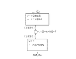
まず、本発明の一実施形態であるデータ記憶装置及びネットワーク機器(データ処理装置)を備える情報処理システムの概略構成について説明する。図1は、本発明の一実施形態であるデータ記憶装置及びネットワーク機器(データ処理装置)を備える情報処理システムの概略構成を示す図である。
Hereinafter, embodiments of the present invention will be described with reference to the drawings.
First, a schematic configuration of an information processing system including a data storage device and a network device (data processing device) according to an embodiment of the present invention will be described. FIG. 1 is a diagram showing a schematic configuration of an information processing system including a data storage device and a network device (data processing device) according to an embodiment of the present invention.
図1において、103a〜103c、104は、ネットワーク機器としてのデータ処理装置であり、例えばMFP(Multi Function Peripheral)と呼ばれる多目的な機能を有する複合機である。これらのネットワーク機器103a〜103c、104は、ネットワーク101に接続されている。本実施形態において、ネットワーク機器104はフルカラーでスキャン、プリントなどが可能なカラーMFPであり、以下MFP104とする。同様に、ネットワーク機器103a〜103cは、モノクロでスキャン、プリントなどを行う白黒MFPであり、以下MFP103とする。105は、コンピュータ端末であり、ネットワーク101に接続する機能や、データ記憶装置102及びMFP103、104を利用する機能を備え、利用者が文書作成などに利用する一般的なコンピュータ端末である。尚、コンピュータ端末105は、CRT(CaThode Ray Tube)や液晶ディスプレイなどの表示装置やキーボードやマウスなどの利用者が操作可能な入力装置を具備する。
In FIG. 1,
102は、データ記憶装置であり、ネットワーク101に接続可能であり、種々のデータを格納する記録媒体を備える装置である。具体的には、データ記憶装置102は、記録媒体としてハードディスクを具備し、iSCSIプロトコルを用いてネットワーク101に接続する。このiSCSIプロトコルとは、記憶装置とコンピュータの通信に使うSCSI(Small Computer System Interface)コマンドを、IP(Internet Protocol)ネットワーク経由で送受信するためのプロトコルである。このiSCSIプロトコルを利用することで、社内LAN(Local Area Network)などのTCP/IP(Transmission Control Protocol/Internet Protocol)ネットワーク上に大容量ハードディスクなどのデータ記憶装置を直に接続して、複数のコンピュータから共用することができるようになる。
以上により、データ記憶装置102は、ネットワーク101を経由してMFP103、104から送られてきた各種データを保存/格納する。100−A〜100−Fは、位置情報提供端子であり、図5に示すように、無線を使った近接通信によりデータ記憶装置102やMFP103、104へ位置情報を提供する装置である。また、位置情報提供端子100−A〜100−Fは、各位置情報提供端子100−A〜100−Fが設置されている場所を特定する位置情報としてフロア階情報(例えば、設置されているフロアの階数及び居室番号)を格納しており、このフロア階情報を位置情報としてデータ記憶装置102やMFP103、104からの要求に応じて送信する。尚、この位置情報は、上述したフロア階情報に限定されるものではなく、データ記憶装置102の設置位置について管理したい範囲や目的に応じて、例えば緯度経度に関する情報や、居室内に仮想的な座標を設けてその座標に関する情報など種々の情報を位置情報として用いて好適である。
As described above, the
[MFP103、104の構成例]
次に、MFP103、104の内部構成例について説明する。
図2は、MFP103、104の内部構成例を示す図である。但し、MFP104とMFP103の差は処理可能な画像/文書がカラーかモノクロかの差であり、色処理以外の部分ではMFP104とMFP103の構成は同等であるため、以下の説明ではMFP104の構成として図2の説明を行い、必要に応じて、随時MFP103の説明を加えることとする。
[Configuration Example of MFPs 103 and 104]
Next, an internal configuration example of the
FIG. 2 is a diagram illustrating an internal configuration example of the
3は、MFP機器内ハードディスクであり、MFP104が具備するハードディスクであり、必要に応じて種々のデータを保存する。5は、操作部であり、MFP104を利用者が操作する際に注視する画面を備える表示部と、その表示部の表示に応じて利用者が操作するボタン等の操作部とから構成される。6は、フォーマッタ部であり、PDL(Page Description Language)データを画像データに展開する。
201は、スキャナ部であり、原稿から画像読み取りを行う。202は、スキャナIP(Image Processor)部であり、スキャナ部201が読み取った画像データに対して画像処理を行う。203は、FAX部であり、ファクシミリなどに代表される電話回線を利用した画像の送受信を行う。204は、NIC(Network Interface Card)部であり、ネットワーク101を介して画像データや装置情報を送受信する。205は、PDL部であり、コンピュータ側から送られてきたページ記述言語(PDL)を画像信号(例えばビットマップ画像信号)に展開する。206は、コア部であり、MFP104の使い方に応じて、各部を制御したり、画像信号を一時保存したり、データの入出経路を決定する。このコア部206には、MFP機器内ハードディスク3、操作部5、フォーマッタ部6及び位置情報取得部9が接続されている。
A
コア部206から出力された画像データは、プリンタIP(Image Processor)部207及びPWM(Pulse Width Mdulation)部208を経由して処理されプリンタ部209に入力される。プリンタ部209は、用紙(印刷媒体)に対して画像データに応じた画像形成(印刷)を行い、フィニッシャ部210は、印刷された用紙の出力及び仕上げの処理を行う。また、位置情報取得部9は、無線通信により、位置情報提供端子100−A〜100−Fの内の一番近接した端子から位置情報を取得しコア部206に伝達する。このように、MFP103およびMFP104が位置情報取得部9を具備することで、MFP103やMFP104の設置場所の変更または、MFP103やMFP104を利用する組織の変更(人の移動)が起きた場合に、ネットワーク101の管理者等が印刷時に利用可能なMFPの位置情報を設定しておくことで、利用者が変更前のMFPを誤って利用してしまうことを防ぐことができる。
The image data output from the
[コア部206の説明]
図3は、図2に示したコア部206のハードウェア構成例及びその周辺構成を示すブロック図である。コア部206は、デジタルビデオI/F(インタフェース)121を備え、上述したスキャナIP部202とデジタルビデオI/F121を介して接続される。また一方でコア部206は、バス125及びI/F(インタフェース)120を介して図2に示したMFP機器内ハードディスク3、操作部5、フォーマッタ部6、NIC部204及び位置情報取得部9と接続される。
[Description of Core Unit 206]
FIG. 3 is a block diagram illustrating a hardware configuration example of the
スキャナ部201にて読み込まれた画像データは、スキャナIP部202、デジタルビデオI/F121及びバス125を介してデータ処理部124へ転送されるとともに、スキャナ部201からの制御コマンドはスキャナIP部202、デジタルビデオI/F121及びバス125を介してCPU(中央演算装置)122へ転送される。データ処理部124は画像の回転処理や変倍処理などの画像処理を行う画像処理手段である。スキャナ部201から転送されデータ処理部124にて処理された画像データは、画像データと同時にCPU122に転送される制御コマンドに応じて、バス125及びI/F120を介してMFP内ハードディスク3またはNIC部204へ転送される。
Image data read by the
また、図1に示したコンピュータ端末105よりNIC部204を介してプリント要求コマンド(PDLデータを含む)が送られてくると、I/F120を介してそのプリント要求コマンドを受信したCPU122は、同時に送られてきたPDLデータをI/F120を介してフォーマッタ部6へ転送する。その後PDLデータはフォーマッタ部6で画像データに展開されI/F120を介して、データ処理部124に転送される。データ処理部124は、フォーマッタ部6から受信した画像データに画象処理を行い、画象処理後の画像データをI/F120を介してプリンタIP部207へ転送する。これにより、プリンタIP部207、PWM部208、プリンタ部209及びフィニッシャ部210を経て画像データがプリント出力される。
When a print request command (including PDL data) is sent from the
上述した処理の間、CPU122は、フォーマッタ部6でのステータスやプリンタIP部207、PWM部208、プリンタ部209及びフィニッシャ部210でのステータスを適時確認し、I/F120を介してNIC部204や位置情報取得部9または、操作部5に対してプリントに関するステータスを伝える。また、CPU122は、メモリ123に記憶されている制御プログラム、及びスキャナ部201から転送された制御コマンドに従って上述したような制御を行う。また、メモリ123はCPU122の作業領域としても使われる。
During the processing described above, the
このように、コア部206は、スキャナ部201及びスキャナIP部202や、MFP機器内ハードディスク3、NIC部204及びフォーマッタ部6に対して、各部間のデータの流れを制御し、原稿画像の読み取り、画像のプリント、コンピュータ端末105とのデータの送受信などの機能を複合させた処理を行うことが可能である。
As described above, the
[データ記憶装置102の内部構成]
図4は、図1に示したデータ記憶装置102の内部構成例を示すブロック図である。図4において、401は、位置情報取得部であり、無線の近接通信で最寄りとなる位置情報提供端子100−A〜100−Fのいずれか一つから図5で示す位置情報を取得する。402は、記憶媒体部であり、データを格納する大容量のハードディスクである。また、記憶媒体部402は、位置情報を用いたアクセス制御情報を格納している。403は、ネットワークインタフェース部であり、iSCSIプロトコルを利用してネットワーク101に接続可能であり、ネットワーク101を介してデータの送受信を行う。404は、操作部であり、データ記憶装置102の状態やエラーなどに関する情報を表示する表示部と、データ記憶装置102の動作を利用者が操作するための操作ボタンとから構成されている。
[Internal Configuration of Data Storage Device 102]
FIG. 4 is a block diagram showing an example of the internal configuration of the
405は、CPUであり、データ記憶装置102の処理全体を統括するとともに内部に暗号化用の暗号鍵を保持している。CPU405は、必要に応じて、この暗号鍵を用いて記憶媒体部402へデータを書き込み/データの読み取りを行う際に、データの暗号化/復号化を行う。また、CPU405は、バス407及びI/F(インタフェース)408を介して、位置情報取得401、記憶媒体部402、ネットワークインタフェース403及び操作部404を制御する。尚、CPU405がデータの暗号化/復号化を行う場合の詳細については後述する。406は、メモリであり、CPU405のワークメモリである。また、データ記憶装置102の構成は、この限りではなく、少なくとも、データを記憶して、記憶したデータをコンピュータ読取可能とする機能と、位置情報を取得する機能と、取得した位置情報に応じて記憶したデータに対して種々の処理を行う機能とを有する構成であればよい。
[データ記憶装置102内部に保持するアクセス制御情報例]
データ記憶装置102内部に保持するアクセス制御情報例について以下に説明する。
図6は、データ記憶装置102内部に保持するアクセス制御情報例を示す図である。図6において、現在位置情報600は、位置情報取得部401が取得した位置情報であって、データ記憶装置102の現在位置に関する情報である。図6に示すように、「31居室(窓側)」というフロア階情報が現在位置情報600として格納されている。ここで、31居室とは、3階の1号室の居室であることを示す。すなわち、2桁目の数字が階数を示し、1桁目の数字が部屋番号を示し、最後の文字「居室」が部屋の種類を示している。例えば、「42実験室」であれば、4階の2号室である実験室を示す。また、上述した(窓側)とは、例えば、図1の位置情報提供端子100−C、100−Fのように窓側にある端子から位置情報を取得した場合に必要に応じて付与される情報である。以下、本実施形態の位置情報としては、上述した「31居室」や「42実験室」と同様のフロア階情報により表現した位置情報を用いる。
[Example of access control information held in the data storage device 102]
An example of access control information held in the
FIG. 6 is a diagram illustrating an example of access control information held in the
ネットワーク稼動許可位置情報601は、データ記憶装置102をネットワーク101に接続して稼動させるエリアを規定している情報である。図6においては、「31居室」が規定されている。位置情報取得部401が取得した位置情報が、このネットワーク稼動許可位置情報601で規定された場所以外である場合には、ネットワーク接続ができないようにデータ記憶装置102自身で制御を行う。
The network operation permission position information 601 is information that defines an area in which the
ハードディスク設置許可位置情報602はデータ記憶装置102を持ち出せる範囲を規定する情報である。図6においては、「31居室、32居室、42実験室、43実験室」の4部屋が規定されている。データ記憶装置102の設定を変更したり修理したりする場合はこのハードディスク設置許可位置情報602で規定されるエリア内部で行う必要がある。もし、位置情報取得部401が取得した位置情報が上述したエリア外であった場合には、「所定の条件」を満たすとデータの漏洩を防ぐ処理として、例えばCPU405内に保持した暗号鍵を廃棄したり、記憶媒体部402に保持したデータを消去したりする処理を行うことで、データの機密保全を行う。尚、上述したデータの漏洩を防ぐ処理を行う為の「所定の条件」の具体例や詳細な処理動作については後述する。
The hard disk installation permission position information 602 is information defining a range in which the
グループ機器設置位置情報603は、データ記憶装置102に対しiSCSIプロトコルを用いてアクセスするMFP103、104の設置位置を規定する情報である。具体的には、MFP103、104の機器グループ(部署単位や設置位置単位などのデータ共有のグループ)を特定するグループIDに、そのグループIDに属する機器の設置位置を特定する位置情報を関連付けた情報である。図6においては、グループID「NATTO1」に位置情報「31居室、32居室、42実験室、43実験室」が関連付けられている。
The group device installation position information 603 is information that defines the installation positions of the
また、グループIDとアクセスキーの対応情報とは、機器グループを特定する情報であるグループID604と、該グループID604に対応する機器グループへハードウェア記憶装置に対するアクセス許可を提供するためのキー(例えば文字列)であるアクセスキー605とを定義する情報である。図6においては、グループID604とアクセスキー606の対応情報として、「NATTO1」と「XXX」及び、「NATTO2」と「YYY」の組み合わせを示している。 The correspondence information between the group ID and the access key includes a group ID 604 that is information for identifying a device group, and a key (for example, a character for providing access permission to the hardware storage device to the device group corresponding to the group ID 604) Column) is an information defining an access key 605. In FIG. 6, as correspondence information between the group ID 604 and the access key 606, combinations of “NATOTO1” and “XXX” and “NATOTO2” and “YYY” are shown.
[MFP103、104内部に保持するアクセス制御情報例]
MFP103、104内部に保持するアクセス制御情報例について以下に説明する。
図7−1及び図7−2は、MFP103及びMFP104内部に保持するアクセス制御情報例を示す図である。ここで、図7−1について説明する。図7−1において、現在位置情報700は、位置情報取得部9が取得した位置情報であって、MFP103の現在位置に関する情報である。具体的には、図7−1に示すように、「31居室(窓側)」というフロア階情報が現在位置情報として格納されている。また、グループ機器設置位置情報501とは、MFPなどの装置が属する上述した機器グループにおいて、その装置の設置位置を規定する情報である。図7−1に示すように、MFP103は、「31居室、32居室、42実験室、43実験室」において設置可能である。
[Example of access control information stored in the MFPs 103 and 104]
An example of access control information held in the
FIGS. 7A and 7B are diagrams illustrating examples of access control information stored in the MFP 103 and the
また、グループIDとアクセスキーの対応情報とは、機器グループを特定する情報であるグループID502と、該グループID502に対応する機器グループに含まれるハードウェア記憶装置に対するアクセス許可を得るためのキー(例えば文字列)であるアクセスキー503とを定義する情報である。図7−1においては、グループID502とアクセスキー503の対応情報として、「NATTO1」と「XXX」の組み合わせを示している。また、BOX識別情報504とは、データ記憶装置102を識別するための情報であり、本実施形態ではハードディスクID(以下、HDID)を用いる。図7−1においては、データ記憶装置102を識別するハードディスクID「共有BOX−A」がBOX識別情報504として格納されている。
The correspondence information between the group ID and the access key includes a group ID 502 that is information for identifying a device group, and a key for obtaining access permission to the hardware storage device included in the device group corresponding to the group ID 502 (for example, This is information that defines an access key 503 that is a character string. FIG. 7A shows a combination of “NATOTO1” and “XXX” as correspondence information between the group ID 502 and the access key 503. The BOX identification information 504 is information for identifying the
次に、図7−2に示す情報例は、図7−1に示したMPF103に関する情報例と同種類のMPF104に関する情報例であり、説明を省略する。尚、MFP103、104は、グループID502及びアクセスキー503を一組として、各装置のグループID502に応じたアクセスキー503をデータ記憶装置102より取得する。この時、MFP103、104は、上述したグループ機器設置位置情報501で規定される位置に設置されている場合のみ、データ記憶装置102からアクセスキー503(データ記憶装置102内においては図6のアクセスキー605)を取得することができる。
Next, the information example illustrated in FIG. 7B is an information example regarding the
次に、図1に示した情報処理システムにおいてデータ記憶装置102の電源を起動した場合の処理について説明する。具体的には、データ記憶装置102の起動処理と、それに応じて、ネットワーク101に接続されるMFP103、104において行われるBOX増設処理とを説明する。ここで、BOX増設処理とは、MPF103、104において、データ記憶装置102を、データの書込み/読み出し可能なハードディスクとして登録する処理である。すなわち、以下の説明においてBOXとは、MFP103、104において、MPF103、104から利用可能に登録されたデータ記憶装置102を示すものである。
Next, processing when the
図8−1は、図1に示した情報処理システムにおいてデータ記憶装置102の電源を起動した場合の処理を示すフローチャートである。利用者がデータ記憶装置102の電源を起動すると、図8−1に示すように、まず、ステップS801において、データ記憶装置102は、位置情報取得部401にて、近接の位置情報端子100から図5に示す位置情報の取得処理を行う。次に、ステップS802において、データ記憶装置102は、位置情報取得部401が位置情報を取得できたか否かを判定する。ここで、位置情報を取得できた場合(ステップS802のYes)には、データ記憶装置102は、図6に示した現在位置情報600に取得した位置情報を現在位置の情報として設定し、ステップS804に進む。また、位置情報が取得できなかった場合(ステップS802のNo)には、データ記憶装置102は、ステップS801に戻り、再度、位置情報の取得処理を行う。すなわち、データ記憶装置102は、起動後に位置情報を取得するまでは、位置情報の取得処理を繰り返し、データにアクセスできない状態となる。
FIG. 8A is a flowchart illustrating processing when the
次に、ステップS804において、データ記憶装置102は、取得した位置情報(現在位置情報600に設定した情報)が、ハードディスク設置許可位置情報602に合致しているか否かを判定する。ここで、合致していると判定した場合(ステップS804のYes)には、データ記憶装置102は、ステップS806に進み、合致していないと判定した場合(ステップS804のNo)には、データ処理装置102は、図8−2(a)に示すステップS805−7の処理を行う。このステップS805−7ではデータが外部に漏洩しないような、データ機密保全の処理を行う。
Next, in step S804, the
ここで、図8−2(a)に示す処理について説明する。
図8−2(a)は、データ記憶装置が設置許可位置外で起動された場合のデータ機密保全の処理例を示すフロー図である。図8−2(a)に示すように、ステップS805−7において、データ記憶装置102は、CPU405で保持している暗号鍵を廃棄するとともに、記憶媒体部402に記憶しているデータを消去する処理を行う。次に、ステップS805−8において、データ記憶装置102は、電源をオフする等の停止処理を行う。以上により、図6に示したハードディスク設置許可位置情報602で規定されている場所以外で、データ記憶装置102が起動された場合には、不正な起動と見なして暗号鍵や記憶しているデータを消去することで、データ機密を保全することができる。
Here, the process shown in FIG.
FIG. 8-2 (a) is a flowchart showing an example of data security processing when the data storage device is activated outside the installation permission position. As shown in FIG. 8-2 (a), in step S805-7, the
図8−1の処理の説明に戻り、ステップS806において、データ記憶装置102は、現在位置情報600の位置情報がネットワーク稼動許可位置情報601に合致しているか否かを判定する。ここで、合致していると判定した場合(ステップS806のYes)には、データ記憶装置102は、ステップS807へ移行し、合致していないと判定した場合(ステップS806のNo)には、データ記憶装置102は、図9に示すステップS901〜S903の処理を行う。この図9の処理については詳細を後述する。
Returning to the description of the processing in FIG. 8A, in step S806, the
次に、ステップS807において、データ記憶装置102は、MFP103、104に対して、現在位置情報600及びハードディスクID(HDID)を同報送信する。尚、以下の説明では、MFP104における、データ記憶装置102から現在位置情報600及びHDIDを受信した場合の処理について説明する。まず、MFP104は、ステップS810において、データ記憶装置102から送られてきた、現在位置情報600及びHDIDを受信する。次に、ステップS811において、MFP104は、データ記憶装置102の現在位置情報600がグループ機器設置位置情報501に合致するか否かを判定する。ここで、合致していると判定した場合(ステップS811のYes)には、MFP103は、ステップS812へ進み、MFP104の現在位置情報700及びグループID502をデータ記憶装置102に送信する。これにより、データ記憶装置102は、MFP104の現在位置情報700及びグループID502を受信し、ステップS808の処理を行う。また、合致していないと判定した場合(ステップS811のNo)には、MFP104は、ステップS810に戻り、データ記憶装置102からの現在位置情報600及びHDIDの受信を待つ。
In step S <b> 807, the
次に、ステップS808において、データ記憶装置102は、MFP104から送信された現在位置情報700とグループID502とを受信し、その値がデータ記憶装置102内部に保持するアクセス制御情報のグループ機器設置位置情報603に合致しているか否かを判定する。ここで、合致していると判定した場合(ステップS808のYes)には、データ記憶装置102は、ステップS809へ移行し、合致していないと判定した場合(ステップS808のNo)には、データ記憶装置102は、起動処理を終了して、通常処理に移行する。
In step S <b> 808, the
次に、ステップS809において、データ記憶装置102は、グループID502及び現在位置情報700を送信して来たMFP104に対し、グループID502と同じグループID604と、対応するアクセスキー605とを一組として送信する。これにより、ステップS813において、MFP104は、データ記憶装置102のグループID604及びアクセスキー605を取得し、これをグループID502及びアクセスキー503として保存する。次に、MFP104は、ステップS814において、データ記憶装置102をBOXとして増設処理して、データ記憶装置102のHDID「共有BOX−A」を、図11で示すように操作部5が備える操作画面5aのBOX識別情報表示エリア1100に表示する。以上により、MFP104において、データ記憶装置102へのデータ格納が可能な状態(BOX増設処理終了)となる。尚、MFP103及びMFP104のそれぞれが、図8−1に示す処理を行う。
In step S809, the
図11は、図1に示したMPF103、104の操作画面例を示す図である。図11に示す様に、操作画面5aには、BOX識別情報表示エリア1100にHDIDが表示されたデータ記憶装置102の設置位置に関する情報「32居室」も合わせて表示されている。また、操作画面5aには、スキャナ部201で原稿を読取開始して、読み取った画像データを共有BOX−A(=データ記憶装置102)へ記録するよう指示するスキャン指示ボタン1101が含まれる。更に、操作画面5aには、共有BOX−A(=データ記憶装置102)に記憶している画像データをプリンタ部209で印刷するよう指示する印刷指示ボタン1102及び、共有BOX−A(=データ記憶装置102)に記憶している画像データをFAX部203で送信するよう指示する送信指示ボタン1103を含む。
FIG. 11 is a diagram showing an example of the operation screen of the
以上に示すように、本実施形態におけるデータ記憶装置102は、起動時に自身の設置位置を確認するとともに、MFP103、104と互いに設置位置を確認した上で、MFP103、104からのデータの書込み/読み出しが可能となる。すなわち、ネットワーク上の機器(データ記憶装置102及びMFP103、104)の相互の位置が保証された状態でデータの送受信を行うことができる。特に、本実施形態における情報処理システムにおいては、起動時のデータ記憶装置102自身の設置位置が適切であるか否かの確認(第1のチェック)と、データ記憶装置102の設置位置がMFP103、104にとって適切な位置であるか否かの確認(第2のチェック)と、MFP103,104の設置位置がデータ記憶装置102にとって適切な位置であるか否かの確認(第3のチェック)との3重のチェックを行うことで、予め定められた場所以外でデータ記憶装置102に格納されるデータが利用されることを防ぐことができる。また、図8−2に示すように、予め定められた場所以外でデータ記憶装置102が利用された場合には、データ記憶装置102自身でデータ漏洩を防ぐ処理を行うことができる。
As described above, the
次に、上述した実施形態においては、データ漏洩を防ぐ処理として図8−2(a)に示す処理を行ったが、この限りではなく、図8−2(b)に示す処理を行っても良い。以下に、図8−2(b)に示すデータ漏洩を防ぐ他の処理について説明する。
図8−2(b)は、図8−1のステップS804でNoである場合のデータ漏洩を防ぐ他の処理例を示す図である。まず、ステップS805−1において、データ記憶装置102は、操作部5の操作画面5aに図14に示すメッセージを表示してアクセス不可を利用者に伝えるとともに、データアクセス復帰のためのパスワードの入力を要求する復帰パスワード入力欄1401を表示する。
Next, in the above-described embodiment, the process illustrated in FIG. 8B is performed as a process for preventing data leakage. However, the present invention is not limited to this, and the process illustrated in FIG. good. Hereinafter, another process for preventing data leakage shown in FIG. 8B will be described.
FIG. 8B is a diagram illustrating another example of processing for preventing data leakage in the case of No in step S804 in FIG. First, in step S805-1, the
次に、ステップS805−2において、データ記憶装置102は、記憶媒体部402内部のファイル管理テーブルを、CPU405内部に保持している暗号鍵で暗号化する。これにより、記憶媒体部402内部のデータ漏洩の危険性をさらに低減することができる。次に、ステップS805−3において、データ記憶装置102は、利用者からの復帰パスワード入力欄1401へのパスワードの入力(復帰操作)を待つ。尚、このような場合には、ステップS805−3においてデータ記憶装置102が利用者からの復帰操作を待つ間に、利用者は、適切な位置にデータ記憶装置102を移動させることができる。また、このパスワードは、データ記憶装置102の正規の利用者にあらかじめ伝えられている情報である。
In step S805-2, the
ここで、復帰パスワード入力欄1401に正しいパスワードが入力された場合(ステップS805−3のYes)には、データ記憶装置102は、ステップS805−4の処理に移行する。また、復帰パスワード入力欄1401に正しいパスワードが入力されずに一定時間が経過した場合(ステップS805−3のNo)には、データ記憶装置102は、上述したステップS805−7のデータ消去処理へ移行する。尚、図8−2(b)のステップS805−7〜S805−8の処理は、上述した図8−2(a)のステップS805−7〜S805−8の処理と同等の処理なので、説明を省略する。
If a correct password is entered in the return password input field 1401 (Yes in step S805-3), the
ステップS805−4において、データ記憶装置102の位置情報取得部401は、近接の位置情報端子100から図5に示す位置情報を取得する。これにより、図6に示した現在位置情報600に取得した位置情報が設定される。次に、ステップS805−5において、データ記憶装置102は、取得した位置情報(現在位置情報600に設定した位置情報)が、ハードディスク設置許可位置情報602に合致しているか否かを判定する。ここで、合致していると判定した場合(ステップS805−5のYes)には、データ記憶装置102は、ステップS805−6に進み、合致していないと判定した場合(ステップS805−5のNo)には、データ処理装置102は、ステップS805−3の処理に戻る。
In step S <b> 805-4, the position
ステップS805−6において、データ記憶装置102は、ステップS805−2で暗号化されたデータ記憶装置102内部のファイル管理テーブルを、CPU405内部に保持している暗号鍵で復号化する。ステップS805−6の処理の後は、図8−1のステップS806へ進む。
In step S805-6, the
以上に示したように、データ記憶装置102が規定外の場所で起動された場合には、暗号化やデータ消去などデータ漏洩を防ぐための種々の対応をデータ記憶装置102の状況に応じて行うことが可能である。
As described above, when the
次に、図8−1のステップS806のNoである場合に、データ記憶装置102がネットワーク稼動許可位置情報601を変更する処理例について説明する。
図9は、図8−1のステップS806のNoである場合に、データ記憶装置102がネットワーク稼動許可位置情報601を変更する処理例を示すフローチャートである。まず、ステップS901において、データ記憶装置102は、図12で示すメッセージ及び設定変更のGUI(Graphical User Interface)を操作部404の操作画面404aに表示する。ここでメッセージとは、例えば図12に示すようにデータ記憶装置102の設置位置がネットワーク稼動許可の位置ではないことを伝えるメッセージである。また、図12において、1200は、更新設定入力エリアであり、更新設定位置及び位置更新パスワードの入力を利用者に促す。また、1201は、設定エリア変更ボタンであり、図6に示したネットワーク稼動許可位置情報601、ハードディスク設置許可位置情報602及びグループ機器設置位置情報603をGUIにより設定する図13に示す画面を表示するためのボタンである。尚、図13については詳細を後述する。
Next, an example of processing in which the
FIG. 9 is a flowchart illustrating a processing example in which the
ここで、図12の更新設定入力エリア1200に利用者が更新設定位置及び位置更新パスワードを入力した場合、ステップS902において、データ記憶装置102は、新たなネットワーク稼動許可位置情報601を変更する情報として、更新設定位置及び位置更新パスワードを受け付ける。次に、ステップS903において、データ記憶装置102は、ステップS902で受け付けた位置更新パスワードの妥当性をチェックするとともに新たなネットワーク稼動許可位置情報601(更新設定位置)がハードディスク設置許可位置情報602の範囲内であるか否かを判定する。ここで位置更新パスワードが妥当でかつ範囲内であると判定した場合(ステップS903のYes)には、ステップS904において、データ記憶装置102は、ネットワーク稼動許可位置情報601を更新する。また、位置更新パスワードが妥当でない及び/または範囲内でないと判定した場合(ステップS903のNo)には、ステップS902に戻る。
Here, when the user inputs the update setting position and the position update password in the update setting
以上に示すように、データ記憶装置102は、ネットワーク接続位置の更新についてもあらかじめ定められた範囲内(ハードディスク設置許可位置の範囲)でのみ設定可能とすることで、予想しない場所でデータ記憶装置102がネットワーク101に接続されることを避けることができるので、データ漏洩の危険性を低減することができる。
As described above, the
[MFP104からデータ記憶装置102へのデータ書き込み]
次に、図8−1に示した処理を終えることで、データ記憶装置102がMFP104のBOXとして設定された場合の、MFP104からデータ記憶装置102へのデータ書き込みを行う際の処理例について説明する。
図10は、MFP104からデータ記憶装置102へのデータ書き込みを行う際の処理例を示すフローチャートである。まず、利用者が図11に示した操作部5の操作画面5aにおけるスキャン指示ボタン1101を押下すると、ステップS1004において、MFP104は、BOX(データ記憶装置102)へのスキャナデータの書き込み指示と認識する。尚、この指示には、紙原稿をスキャン処理する指示も含まれている。
[Data writing from
Next, an example of processing when data is written from the
FIG. 10 is a flowchart illustrating an example of processing when data is written from the
次に、ステップS1005において、MFP104は、ステップS1004で認識した指示に応じて、紙原稿をスキャナ部201で読み取り、BOXへの格納対象となるデータファイルを作成する。次に、ステップS1006において、MFP104は、作成したデータファイルにMFP104のグループID502及びグループID502に対応するデータ記憶装置102のアクセスキー503を付加する。具体的には、MFP104は、データファイルの属性情報中にグループID502及びアクセスキー503を格納する。次に、ステップS1007において、MFP104は、作成したデータファイルを、iSCSIプロトコルを用いてデータ記憶装置102へ送信する。以上により、MFP104は、BOX(データ記憶装置102)へのデータ格納処理を終了する。
In step S1005, the
次に、ステップS1001において、データ記憶装置102は、MFP104からのデータファイルを受信する。次に、ステップS1002において、データ記憶装置102は、受信したデータファイルの属性情報を参照して、付加されているグループID502及びアクセスキー503が妥当であるか否かを判断する。ここで、妥当であると判断した場合(ステップS1002のYes)には、ステップS1003に進み、データ記憶装置102は、グループID502に対応するハードディスク(記憶媒体部402)の格納領域にデータファイルを格納する。
In step S <b> 1001, the
以上に示したように、MFP104は、データ記憶装置102をBOXとして登録することで、データ記憶装置102をあたかも内蔵ハードディスクのように利用することができる。
As described above, the
[設置エリア設定画面例]
図13は、データ記憶装置102に関する種々の設定エリアを表示/変更するための画面例を示す図である。この図13に示す画面例は、上述したように図12に示す操作画面404aの設定エリア変更ボタン1201を利用者が押下することで、表示される画面例である。図13に示すように、3階フロアにある31居室および32居室におけるデータ記憶装置102の設定エリアとして、ネットワーク稼動許可エリア132、ハードディスク設置許可エリア131及びグループ危機設置エリア130を設定可能である。これらの、ネットワーク稼動許可エリア132、ハードディスク設置許可エリア131及びグループ危機設置エリア130は、図6に示したネットワーク稼動許可位置情報601、ハードディスク設置許可位置情報602及びグループ機器設置位置情報603で特定されるエリアである。この画面において、利用者は、GUIにより設定エリアを変更することができる。このように、設定エリアを視覚的に表示することで、利用者は、グループ機器の設置エリアとデータ記憶装置102の相互の位置関係を把握することが容易となる。
[Installation area setting screen example]
FIG. 13 is a diagram showing an example of a screen for displaying / changing various setting areas related to the
尚、図8−1のステップS810〜S814に示す処理及び図10のステップS1004〜S1007に示す処理は、MFP103、104のCPU122が各処理を実現するためのプログラムを実行することで実現している。また、図8−1のステップS801〜S809に示す処理と、図8−2のステップS805−1〜S805−8に示す処理と、図9のステップS901〜S904に示す処理と、図10のステップS1001〜S1003に示す処理は、データ記憶装置102のCPU405が各処理を実現するためのプログラムを実行することで実現している。
The processes shown in steps S810 to S814 in FIG. 8A and the processes shown in steps S1004 to S1007 in FIG. 10 are realized by the
また、上述したデータ記憶装置102は、データを記憶する手段としてハードディスクを用いていたが、これに限定されるものではなく、フラッシュメモリ等の不揮発性のメモリなど種々の記録媒体を、データを記憶する手段として用いて好適である。また、上述したデータ記憶装置102は、表示部を備えた操作部404を具備していたが、この限りではなく、例えば、図1のコンピュータ端末105が、操作部404の代わりの機能を担ってもよい。即ち、コンピュータ端末105が、データ記憶装置102からステータス情報やアクセス制御情報などを取得して、図12や図13に示した画面を表示してもよい。
The
また、上述した実施形態では、データ記憶装置102及びMFP103、104における図8−1、図8−2、図9及び図10に示した種々の処理を実現する為のプログラムをメモリより読み出してCPUが実行することにより、その処理機能を実現させるものであったが、この限りではなく、各処理の全部または一部の機能を専用のハードウェアにより実現してもよい。
In the above-described embodiment, the program for realizing the various processes shown in FIGS. 8A, 8B, 9C, and 10 in the
また、上述したメモリは、光磁気ディスク装置、フラッシュメモリ等の不揮発性のメモリや、CD−ROM等の読み出しのみが可能な記録媒体、RAM以外の揮発性のメモリ、あるいはこれらの組み合わせによるコンピュータ読み取り、書き込み可能な記録媒体より構成されてもよい。 The above-mentioned memory is a non-volatile memory such as a magneto-optical disk device or a flash memory, a recording medium such as a CD-ROM that can only be read, a volatile memory other than a RAM, or a computer read by a combination thereof. The recording medium may be a writable recording medium.
また、上述したデータ記憶装置102及びMFP103、104において各種処理を行う機能の一部を実現する為のプログラムをコンピュータ読み取り可能な記録媒体に記録して、この記録媒体に記録されたプログラムをコンピュータシステムに読み込ませ、実行することにより一部の処理を行っても良い。なお、ここでいう「コンピュータシステム」とは、OSや周辺機器等のハードウェアを含むものとする。
Further, a program for realizing a part of the functions for performing various processes in the
また、上記プログラムは、このプログラムを記憶装置等に格納したコンピュータシステムから、伝送媒体を介して、あるいは、伝送媒体中の伝送波により他のコンピュータシステムに伝送されてもよい。ここで、プログラムを伝送する「伝送媒体」は、インターネット等のネットワーク(通信網)や電話回線等の通信回線(通信線)のように情報を伝送する機能を有する媒体のことをいう。 The program may be transmitted from a computer system storing the program in a storage device or the like to another computer system via a transmission medium or by a transmission wave in the transmission medium. Here, the “transmission medium” for transmitting the program refers to a medium having a function of transmitting information, such as a network (communication network) such as the Internet or a communication line (communication line) such as a telephone line.
また、上記プログラムは、前述した機能の一部を実現する為のものであっても良い。さらに、前述した機能をコンピュータシステムに既に記録されているプログラムとの組み合わせで実現できるもの、いわゆる差分ファイル(差分プログラム)であっても良い。 The program may be for realizing a part of the functions described above. Furthermore, what can implement | achieve the function mentioned above in combination with the program already recorded on the computer system, and what is called a difference file (difference program) may be sufficient.
また、上記のプログラムを記録したコンピュータ読み取り可能な記録媒体等のプログラムプロダクトも本発明の実施形態として適用することができる。
以上、この発明の実施形態について図面を参照して詳述してきたが、具体的な構成はこの実施形態に限られるものではなく、この発明の要旨を逸脱しない範囲の設計等も含まれる。
また、本実施形態に係るデータ記憶装置、情報処理システム及びデータ記憶方法は、データを記憶する記録媒体(記憶媒体)を具備するデータ記憶装置において、特定した位置に応じて記録媒体に記憶されているデータの読み出しを不能にする制御を行うので、予め定められた場所以外でデータ記憶装置が利用された場合にはデータ漏洩を防ぐ処理を行うことができる。また、上述したデータ記憶装置及びデータ処理装置がネットワークに接続された構成である情報処理システムにおいて、データ処理装置で利用するデータをデータ記憶装置に格納して一元管理することで、ネットワークに接続された複数のデータ処理装置で利用するデータの管理を簡便にすることができる。
A program product such as a computer-readable recording medium in which the above program is recorded can also be applied as an embodiment of the present invention.
The embodiment of the present invention has been described in detail with reference to the drawings. However, the specific configuration is not limited to this embodiment, and includes designs and the like that do not depart from the gist of the present invention.
In addition, the data storage device, the information processing system, and the data storage method according to the present embodiment are stored in a recording medium according to a specified position in a data storage device including a recording medium (storage medium) that stores data. Therefore, when the data storage device is used at a place other than a predetermined location, a process for preventing data leakage can be performed. Further, in the information processing system in which the data storage device and the data processing device described above are connected to the network, the data used by the data processing device is stored in the data storage device and managed centrally, thereby being connected to the network. In addition, management of data used by a plurality of data processing devices can be simplified.
5、404 操作部
9、401 位置情報取得部
100−A〜F 位置情報提供端子
101 ネットワーク
102 データ記憶装置
103a〜c MFP(白黒)
104 MFP(カラー)
105 コンピュータ端末
122、405 CPU
123、406 メモリ
124 データ処理部
206 コア部
204 NIC部
402 記憶媒体部
404 ネットワークインタフェース部
5, 404
104 MFP (color)
105
123, 406
Claims (7)
異なる属性を有する複数の区域を示す区域情報を格納する情報格納手段と、
外部からの信号を受信して位置を特定する位置特定手段と、
前記位置特定手段によって特定される位置が第1の属性を有する第1の区域内でなければ、前記記憶媒体に記憶されているデータの読み出しを不能にする制御を行い、前記位置特定手段によって特定される位置が第2の属性を有する第2の区域内でなければ、前記情報格納手段に格納されている区域情報の変更を不能にする制御を行う制御手段と
を具備し、
前記制御手段は、前記位置特定手段によって特定される位置が前記第1の区域内ではなく、前記第2の区域内である場合、前記記憶媒体に記憶されているデータの読み出しを不能にする制御を行い、前記情報格納手段に格納されている区域情報の変更を可能にする制御を行うこと
を特徴とするデータ記憶装置。 A data storage device comprising a storage medium for storing data,
Information storage means for storing area information indicating a plurality of areas having different attributes;
A position specifying means for receiving a signal from the outside and specifying the position;
If the position specified by the position specifying means is not within the first zone having the first attribute, control is performed to disable reading of data stored in the storage medium, and the position specifying means specifies the position. Control means for performing control to disable change of the area information stored in the information storage means if the position to be performed is not within the second area having the second attribute ,
The control means is configured to disable reading of data stored in the storage medium when the position specified by the position specifying means is not in the first area but in the second area. And a control for enabling change of the area information stored in the information storage means .
異なる属性を有する複数の区域を示す区域情報を格納する情報格納手段と、
外部から位置情報を受信する受信手段と、
前記受信手段により受信される位置情報が示す位置が第1の属性を有する第1の区域内でなければ、前記記憶媒体に記憶されているデータの読み出しを不能にする制御を行い、前記受信手段により受信される位置情報が示す位置が第2の属性を有する第2の区域内でなければ、前記情報格納手段に格納されている区域情報の変更を不能にする制御を行う制御手段と
を具備し、
前記制御手段は、前記受信手段により受信される位置情報が示す位置が前記第1の区域内ではなく、前記第2の区域内である場合、前記記憶媒体に記憶されているデータの読み出しを不能にする制御を行い、前記情報格納手段に格納されている区域情報の変更を可能にする制御を行うこと
を特徴とするデータ記憶装置。 A data storage device comprising a storage medium for storing data,
Information storage means for storing area information indicating a plurality of areas having different attributes;
Receiving means for receiving position information from outside;
If the first zone to the position indicated by the positional information that will be received by the receiving means has a first attribute, it performs control to disable the reading of data stored in the storage medium, the receiving means Control means for performing control to disable change of the area information stored in the information storage means if the position indicated by the position information received by is not within the second area having the second attribute And
The control means cannot read the data stored in the storage medium when the position indicated by the position information received by the receiving means is not in the first area but in the second area. A data storage device characterized by performing control for enabling the change of area information stored in the information storage means .
前記制御手段は、前記位置が前記第2の区域外である場合、前記記憶媒体に記憶されているデータを消去することを特徴とする請求項1乃至3の何れか1項に記載のデータ記憶装置。 4. The data storage according to claim 1, wherein the control unit erases data stored in the storage medium when the position is outside the second area. 5. apparatus.
前記制御手段は、前記記憶媒体に記憶されているデータの読み出しを不能にする処理として、前記記憶媒体中のデータ消去を行う場合には、前記データ格納手段が格納する前記暗号化用データの消去を行うことを特徴とする請求項6に記載のデータ記憶装置。In the case of erasing data in the storage medium as a process for making it impossible to read data stored in the storage medium, the control means erases the encryption data stored in the data storage means The data storage device according to claim 6, wherein:
Priority Applications (3)
| Application Number | Priority Date | Filing Date | Title |
|---|---|---|---|
| JP2003391064A JP4574162B2 (en) | 2003-11-20 | 2003-11-20 | Data storage |
| US10/555,308 US7315925B2 (en) | 2003-11-20 | 2004-11-10 | Disabling access based on location |
| PCT/JP2004/017041 WO2005050458A1 (en) | 2003-11-20 | 2004-11-10 | Data storage apparatus, data processing apparatus, information processing system, and data storage method |
Applications Claiming Priority (1)
| Application Number | Priority Date | Filing Date | Title |
|---|---|---|---|
| JP2003391064A JP4574162B2 (en) | 2003-11-20 | 2003-11-20 | Data storage |
Publications (3)
| Publication Number | Publication Date |
|---|---|
| JP2005157476A JP2005157476A (en) | 2005-06-16 |
| JP2005157476A5 JP2005157476A5 (en) | 2010-03-18 |
| JP4574162B2 true JP4574162B2 (en) | 2010-11-04 |
Family
ID=34616359
Family Applications (1)
| Application Number | Title | Priority Date | Filing Date |
|---|---|---|---|
| JP2003391064A Expired - Fee Related JP4574162B2 (en) | 2003-11-20 | 2003-11-20 | Data storage |
Country Status (3)
| Country | Link |
|---|---|
| US (1) | US7315925B2 (en) |
| JP (1) | JP4574162B2 (en) |
| WO (1) | WO2005050458A1 (en) |
Families Citing this family (26)
| Publication number | Priority date | Publication date | Assignee | Title |
|---|---|---|---|---|
| US7203967B2 (en) * | 2003-09-10 | 2007-04-10 | Qualcomm Incorporated | Methods and apparatus for content protection in a wireless network |
| JP4813872B2 (en) * | 2005-11-21 | 2011-11-09 | 株式会社日立製作所 | Computer system and data replication method of computer system |
| WO2007063437A2 (en) * | 2005-11-29 | 2007-06-07 | Nxp B.V. | Storage media |
| US20070155364A1 (en) * | 2006-01-03 | 2007-07-05 | Stefan Andersson | Method and system for content based obligation enforcement in an electronic equipment |
| CN101047961B (en) * | 2006-03-31 | 2012-10-10 | 联想(北京)有限公司 | Radio network system and moving terminal |
| US8612556B2 (en) * | 2006-05-03 | 2013-12-17 | Comcast Cable Holdings, Llc | Method of provisioning network elements |
| JP4929871B2 (en) * | 2006-06-27 | 2012-05-09 | 富士通株式会社 | Information leakage prevention program, information leakage prevention method and information leakage prevention apparatus |
| JP4960130B2 (en) * | 2007-03-30 | 2012-06-27 | Kddi株式会社 | File management system, file management method and program |
| JP4933327B2 (en) * | 2007-03-30 | 2012-05-16 | Kddi株式会社 | File management system, file management method and program |
| EP2176808A2 (en) * | 2007-08-01 | 2010-04-21 | Nxp B.V. | Mobile communication device and method for disabling applications |
| JP4770814B2 (en) * | 2007-09-03 | 2011-09-14 | 日本電気株式会社 | iSCSI storage system, iSCSI operation method, and iSCSI operation program |
| JP2009093449A (en) | 2007-10-10 | 2009-04-30 | Sony Corp | Recording medium, data use limiting method and program |
| JP2009109940A (en) * | 2007-11-01 | 2009-05-21 | Seiko Epson Corp | Projector and control method thereof |
| JP5020857B2 (en) * | 2008-02-20 | 2012-09-05 | 株式会社日立製作所 | Computer system and terminal |
| JP5304066B2 (en) * | 2008-07-11 | 2013-10-02 | 富士通株式会社 | Information processing apparatus, information processing method, and information processing program |
| JP2010128636A (en) * | 2008-11-26 | 2010-06-10 | Pioneer Electronic Corp | Information recording system and portable recording medium |
| JP5305895B2 (en) * | 2008-12-26 | 2013-10-02 | 三菱電機株式会社 | Reporting device and elevator car |
| JP2010177782A (en) * | 2009-01-27 | 2010-08-12 | Canon Inc | Communication apparatus, and control method thereof |
| US8583924B2 (en) * | 2009-07-01 | 2013-11-12 | Hand Held Products, Inc. | Location-based feature enablement for mobile terminals |
| US10024971B2 (en) | 2013-07-16 | 2018-07-17 | Walter Fields | Apparatus, system and method for locating a lost instrument or object |
| JP5897528B2 (en) * | 2013-09-30 | 2016-03-30 | 京セラドキュメントソリューションズ株式会社 | Security processing apparatus and security processing method |
| JP5922080B2 (en) * | 2013-10-31 | 2016-05-24 | 京セラドキュメントソリューションズ株式会社 | Image forming apparatus |
| US9378383B2 (en) * | 2014-08-21 | 2016-06-28 | Seagate Technology Llc | Location based disk drive access |
| JP6714807B2 (en) * | 2015-09-04 | 2020-07-01 | 富士ゼロックス株式会社 | Information processing apparatus, image forming apparatus and program |
| US10341361B2 (en) | 2017-06-05 | 2019-07-02 | Hewlett Packard Enterprise Development Lp | Transmitting secure information |
| CN112468968A (en) * | 2021-02-03 | 2021-03-09 | 北京电信易通信息技术股份有限公司 | Management method and system of portable equipment |
Citations (6)
| Publication number | Priority date | Publication date | Assignee | Title |
|---|---|---|---|---|
| JPH0981516A (en) * | 1995-09-14 | 1997-03-28 | Toshiba Corp | Information apparatus and information providing method |
| JPH09319662A (en) * | 1996-05-29 | 1997-12-12 | Seiko Epson Corp | Information processor, information providing system, information managing method and recording medium |
| JPH10293728A (en) * | 1997-04-17 | 1998-11-04 | Canon Inc | Data processor, data processing method and storage medium storing program readable by computer |
| JP2002312144A (en) * | 2001-04-12 | 2002-10-25 | Canon Inc | Printing system, printing method, information processing device, program and recording medium |
| JP2003018652A (en) * | 2001-06-29 | 2003-01-17 | Casio Comput Co Ltd | Data processing system and program |
| JP2003099400A (en) * | 2001-09-26 | 2003-04-04 | Fujitsu Ltd | Security-managing device, security-managing method and security-managing program |
Family Cites Families (10)
| Publication number | Priority date | Publication date | Assignee | Title |
|---|---|---|---|---|
| JP4026960B2 (en) | 1998-07-31 | 2007-12-26 | キヤノン株式会社 | Image position management apparatus, image position management method, and storage medium storing computer-readable program |
| US6775023B1 (en) | 1999-07-30 | 2004-08-10 | Canon Kabushiki Kaisha | Center server, information processing apparatus and method, and print system |
| US20030110011A1 (en) | 2000-03-31 | 2003-06-12 | Satoshi Kyotoku | Software unlawful use prevention apparatus |
| JP2001306530A (en) | 2000-04-25 | 2001-11-02 | Canon Inc | Network system, device and method for performing remote access and computer-readable storage medium |
| JP2003085025A (en) * | 2001-09-13 | 2003-03-20 | Seiko Instruments Inc | Attribute control system of storage device |
| JP2003233534A (en) * | 2002-02-07 | 2003-08-22 | Hitachi Ltd | Memory system |
| US7114037B2 (en) * | 2002-07-11 | 2006-09-26 | Oracle International Corporation | Employing local data stores to maintain data during workflows |
| EP1450261A1 (en) * | 2003-02-18 | 2004-08-25 | STMicroelectronics S.r.l. | Semiconductor memory with access protection scheme |
| JP4266725B2 (en) * | 2003-06-27 | 2009-05-20 | 株式会社日立製作所 | Storage system |
| US20050138314A1 (en) * | 2003-12-23 | 2005-06-23 | Ming-Jen Liang | Write-protected micro memory device |
-
2003
- 2003-11-20 JP JP2003391064A patent/JP4574162B2/en not_active Expired - Fee Related
-
2004
- 2004-11-10 US US10/555,308 patent/US7315925B2/en not_active Expired - Fee Related
- 2004-11-10 WO PCT/JP2004/017041 patent/WO2005050458A1/en active Application Filing
Patent Citations (6)
| Publication number | Priority date | Publication date | Assignee | Title |
|---|---|---|---|---|
| JPH0981516A (en) * | 1995-09-14 | 1997-03-28 | Toshiba Corp | Information apparatus and information providing method |
| JPH09319662A (en) * | 1996-05-29 | 1997-12-12 | Seiko Epson Corp | Information processor, information providing system, information managing method and recording medium |
| JPH10293728A (en) * | 1997-04-17 | 1998-11-04 | Canon Inc | Data processor, data processing method and storage medium storing program readable by computer |
| JP2002312144A (en) * | 2001-04-12 | 2002-10-25 | Canon Inc | Printing system, printing method, information processing device, program and recording medium |
| JP2003018652A (en) * | 2001-06-29 | 2003-01-17 | Casio Comput Co Ltd | Data processing system and program |
| JP2003099400A (en) * | 2001-09-26 | 2003-04-04 | Fujitsu Ltd | Security-managing device, security-managing method and security-managing program |
Also Published As
| Publication number | Publication date |
|---|---|
| US20060212664A1 (en) | 2006-09-21 |
| US7315925B2 (en) | 2008-01-01 |
| WO2005050458A1 (en) | 2005-06-02 |
| JP2005157476A (en) | 2005-06-16 |
Similar Documents
| Publication | Publication Date | Title |
|---|---|---|
| JP4574162B2 (en) | Data storage | |
| JP4957732B2 (en) | Access restriction file, restriction file generation device, file generation device control method, file generation program | |
| JP4826828B2 (en) | Output system, network device, output control program, and output method | |
| JP4938011B2 (en) | File management system and method, and portable terminal device | |
| EP3330847B1 (en) | Information processing apparatus, control method for the information processing apparatus, program, and storage program | |
| JP2005014591A (en) | Authentication performing system, authentication printing system, network printer, printer managing terminal, program for printer, program for terminal, and authentication printing method | |
| JP6656112B2 (en) | Printing system, image forming apparatus, printing method, and communication method | |
| JP2007174062A (en) | Data communication apparatus, data communication system, data communication method, and program thereof | |
| JP4684901B2 (en) | Printing system, printing apparatus, printing apparatus control method and program | |
| JP2007334881A (en) | Method and system for monitoring unprocessed operation for image processing | |
| US8370900B2 (en) | Image forming apparatus | |
| JP2008293266A (en) | Image processing system | |
| JP5111974B2 (en) | Communication system and communication apparatus | |
| CN1835456B (en) | Communication system, communication device, and communication method | |
| JP2005348250A (en) | Image forming device, data encipher method, program, and recording medium | |
| JP2009026038A (en) | Information processor, program, and recording medium | |
| JP2002342061A (en) | Image forming system and method, computer readable recording medium having the program recorded thereon, image forming apparatus and program | |
| JP7248947B2 (en) | Image forming device and home screen display program | |
| US11553104B2 (en) | Information processing apparatus capable of controlling a document stored in a memory not to leak to a network not permitted to access and non-transitory computer readable medium | |
| EP3606122B1 (en) | Information processing method and information processing system | |
| JP2013003933A (en) | Information processor, information management method and information management program | |
| JP2007179140A (en) | Printing system, printer, and printing controller | |
| US20240069816A1 (en) | System including first device copying shortcut information to portable memory, and second device performing shortcut related process based on the shortcut information stored in the portable memory | |
| JP5223553B2 (en) | Information processing apparatus, image processing apparatus, information processing method, and information processing program | |
| JP2006227832A (en) | Service providing device, information terminal device, service providing system, and service providing method |
Legal Events
| Date | Code | Title | Description |
|---|---|---|---|
| A521 | Request for written amendment filed |
Free format text: JAPANESE INTERMEDIATE CODE: A523 Effective date: 20061106 |
|
| A621 | Written request for application examination |
Free format text: JAPANESE INTERMEDIATE CODE: A621 Effective date: 20061106 |
|
| A521 | Request for written amendment filed |
Free format text: JAPANESE INTERMEDIATE CODE: A523 Effective date: 20100203 |
|
| A131 | Notification of reasons for refusal |
Free format text: JAPANESE INTERMEDIATE CODE: A131 Effective date: 20100420 |
|
| A521 | Request for written amendment filed |
Free format text: JAPANESE INTERMEDIATE CODE: A523 Effective date: 20100617 |
|
| TRDD | Decision of grant or rejection written | ||
| A01 | Written decision to grant a patent or to grant a registration (utility model) |
Free format text: JAPANESE INTERMEDIATE CODE: A01 Effective date: 20100803 |
|
| A01 | Written decision to grant a patent or to grant a registration (utility model) |
Free format text: JAPANESE INTERMEDIATE CODE: A01 |
|
| A61 | First payment of annual fees (during grant procedure) |
Free format text: JAPANESE INTERMEDIATE CODE: A61 Effective date: 20100818 |
|
| R150 | Certificate of patent or registration of utility model |
Free format text: JAPANESE INTERMEDIATE CODE: R150 |
|
| FPAY | Renewal fee payment (event date is renewal date of database) |
Free format text: PAYMENT UNTIL: 20130827 Year of fee payment: 3 |
|
| LAPS | Cancellation because of no payment of annual fees |