JP4573244B2 - Information processing apparatus, control method, and program - Google Patents
Information processing apparatus, control method, and program Download PDFInfo
- Publication number
- JP4573244B2 JP4573244B2 JP2004380790A JP2004380790A JP4573244B2 JP 4573244 B2 JP4573244 B2 JP 4573244B2 JP 2004380790 A JP2004380790 A JP 2004380790A JP 2004380790 A JP2004380790 A JP 2004380790A JP 4573244 B2 JP4573244 B2 JP 4573244B2
- Authority
- JP
- Japan
- Prior art keywords
- information
- imaging
- camera
- detection device
- sensor
- Prior art date
- Legal status (The legal status is an assumption and is not a legal conclusion. Google has not performed a legal analysis and makes no representation as to the accuracy of the status listed.)
- Expired - Fee Related
Links
Images


Description
本発明は、監視カメラの動作を制御する技術に関する。 The present invention relates to a technique for controlling the operation of a surveillance camera.
監視カメラの動作を制御する技術としては、監視が必要な場所に例えば不審者の侵入等のイベントを検知するセンサと監視カメラとを設置し、センサのイベント検知に基づいて監視カメラの動作を制御するカメラ制御装置が提案されている(特許文献1,2)。
As a technology to control the operation of the surveillance camera, a sensor and a surveillance camera that detect an event such as an intrusion of a suspicious person, for example, are installed in a place that requires monitoring, and the operation of the surveillance camera is controlled based on the event detection of the sensor A camera control device has been proposed (
特許文献1には、センサのイベント検知に基づいて監視カメラの動作を制御し、撮影内容とセンサの検出履歴とを記録して、センサの検出履歴を一覧表示することで、オペレータが異常の発生とその時の撮影内容とを容易に知ることのできる構成が開示されている。また、特許文献2には、センサのイベント検知に基づいて監視カメラの動作を制御し、侵入が発生した地点に向けて音声メッセージを出力することで、侵入を発見するとともに、不審者に対して迅速に対応することのできる構成が開示されている。
しかしながら、上記従来の技術においては、状況に合わせて複数の監視カメラの動作を関連づけ、全体として適切な映像を撮影するように監視カメラの動作を制御することができなかった。 However, in the above-described conventional technology, it is impossible to associate the operations of a plurality of surveillance cameras in accordance with the situation and control the operations of the surveillance cameras so as to capture an appropriate video as a whole.
本発明は上記問題に鑑みなされたものであり、複数のセンサと複数の監視カメラを予め定められた優先順位に従って、イベント検知中のセンサとセンサイベントに対応可能な監視カメラを指定し、指定された監視カメラの撮影制御をセンサイベント対応モードに切り替える事により全体として適切な映像を撮影することを可能にする技術を提供することを目的とする。
The present invention has been made in view of the above-described problem. A plurality of sensors and a plurality of surveillance cameras are designated according to a predetermined priority order, and a sensor that can detect an event and a surveillance camera that can respond to the sensor event are designated and designated. It is an object of the present invention to provide a technique that makes it possible to shoot an appropriate video as a whole by switching the shooting control of a surveillance camera to a sensor event response mode .
上記目的を達成するため、例えば本発明による情報処理装置は以下の構成を備える。即ち、
イベント情報を検出する複数の検知装置と、画像を撮像する複数の撮像装置とに接続された情報処理装置であって、
前記複数の検知装置に個別に割り当てられた検知装置識別情報の各々に対して、対応する複数の撮像装置の識別情報と、当該複数の撮像装置の優先順位情報とを設けた第1の管理情報を記憶する第1の記憶手段と、
前記複数の検知装置の1つが前記イベント情報を検知した場合に、当該イベント情報を検知した検知装置の検知装置識別情報を受信する受信手段と、
前記第1の管理情報に基づいて、前記受信した前記検知装置識別情報と対応付けられた複数の撮像装置を選定する第1の選定手段と、
前記第1の選定手段が選定した前記複数の撮像装置の中から、前記第1の管理情報の優先順位情報に基づいて1つの撮像装置を選定する第2の選定手段と、
前記複数の撮像装置に個別に割り当てられた撮像装置識別情報の各々に対して、対応する複数の検知装置の検知装置識別情報と、当該複数の検知装置の優先順位情報とを設けた第2の管理情報を記憶する第2の記憶手段と、
前記受信手段が受信した検知装置識別情報に対応付けられた第1の検知装置と、前記第2の管理情報において前記1つの撮像装置に対応付けられた第2の検知装置との優先順位を、前記第2の管理情報の優先順位情報に基づいて判断する第1の判断手段と、
前記第1の判断手段が、前記第1の検知装置の優先順位が高いと判断した場合に、前記1つの撮像装置を、前記第1の検知装置のイベント情報に対応した制御設定で制御させる第1の撮像装置として指定する指定手段と、
を備える。
In order to achieve the above object, for example, an information processing apparatus according to the present invention comprises the following arrangement. That is,
An information processing apparatus connected to a plurality of detection devices that detect event information and a plurality of imaging devices that capture an image,
First management information provided with identification information of a plurality of corresponding imaging devices and priority information of the plurality of imaging devices for each of the detection device identification information individually assigned to the plurality of detection devices. First storage means for storing
When the one of the plurality of sensing devices, but it detects the event information, the receiving unit that will receive detection device identification information of the detecting device detects the event information,
Based on the first management information, a first selection constant means for selecting a plurality of imaging devices that is associated with said received the detection device identification information,
Second selection means for selecting one imaging device based on priority information of the first management information from among the plurality of imaging devices selected by the first selection means;
A second set of detection device identification information of a plurality of corresponding detection devices and priority order information of the plurality of detection devices is provided for each of the imaging device identification information individually assigned to the plurality of imaging devices. Second storage means for storing management information;
The priority order of the first detection device associated with the detection device identification information received by the reception unit and the second detection device associated with the one imaging device in the second management information, First determination means for determining based on priority information of the second management information;
When the first determination unit determines that the priority order of the first detection device is high, the first image pickup device is controlled with a control setting corresponding to the event information of the first detection device. Designation means for designating as one imaging device ;
Is provided.
本発明によれば、複数のセンサと複数の監視カメラを予め定められた優先順位に従って、イベント検知中のセンサとセンサイベントに対応可能な監視カメラを指定し、指定された監視カメラの撮影制御をセンサイベント対応モードに切り替える事により全体として適切な映像を撮影することを可能にする技術を提供することができる。 According to the present invention, a plurality of sensors and a plurality of monitoring cameras are designated according to a predetermined priority order, a sensor that is detecting an event and a monitoring camera that can respond to the sensor event are designated, and shooting control of the designated monitoring camera is performed. By switching to the sensor event response mode, it is possible to provide a technique that enables an appropriate video to be taken as a whole.
以下、添付図面を参照して本発明に係る実施の形態を詳細に説明する。ただし、この実施の形態に記載されている構成要素はあくまでも例示であり、この発明の範囲をそれらのみに限定する趣旨のものではない。 Embodiments according to the present invention will be described below in detail with reference to the accompanying drawings. However, the constituent elements described in this embodiment are merely examples, and are not intended to limit the scope of the present invention only to them.
<<第1実施形態>>
(システム構成)
図1は本実施形態に対応する情報処理装置を組み込んだ監視カメラシステムの構成を示すブロック図である。
<< First Embodiment >>
(System configuration)
FIG. 1 is a block diagram showing the configuration of a surveillance camera system incorporating an information processing apparatus corresponding to this embodiment.
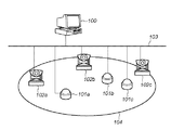
図1に示すように、監視カメラシステムは、サーバ100と、センサ101a、101b、101c(以下、まとめて101で指示する)、監視カメラ(以下、カメラと呼ぶ)102a、102b、102c(以下、まとめて102で指示する)、及び、それらが互いに接続されたネットワーク103から構成されている。104は、監視カメラシステムが監視を行う監視領域である。
As shown in FIG. 1, the surveillance camera system includes a
サーバ100は、センサ101から送られるセンサイベント信号に基づいてカメラ102の動作を制御し、カメラ102より送られてくる動画像を適宜記録する情報処理装置であり、ワークステーション(WS)やパーソナルコンピュータ(PC)等の情報処理装置によって実現される。
The
センサ101は、所定のイベントを検出し、センサイベント信号(イベント検出信号)をサーバ100へ送信する感知装置である。センサ101は、例えば、圧力センサや、熱センサ、衝撃センサ、光センサ、振動センサ、音響センサ、ドアの開閉センサ等が含まれる。カメラ102は、光の入射を検出して動画像を撮像し、撮像した動画像の情報(撮像データ、画像情報)を所定の装置に送出する撮像装置である。カメラ102は、外部からの動作信号を入力することによりパン、チルト、ズーム等の動作を制御することができる。感知装置とは、センサ単体に限らず、周辺回路(例えばレベル変換回路データ記憶回路、バッファ回路、外部インタフェース回路等のいずれか)を含むセンサ装置を含む。
The
ネットワーク103は、典型的には、インターネットであるが、有線/無線を問わず、公衆回線(アナログ回線、ISDN等)やLAN、WAN、無線LAN等のデータ送受信可能な回線であれば、どのような構成でもよい。ネットワークを用いた通信プロトコルは、例えば、TCP/IP等を採用する。本実施形態においては、監視領域104に正当な権限なく侵入した侵入者を検出する場合を想定するが、本実施形態の適用範囲はこれに限られるものではない。
The
(サーバの構成)
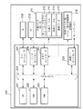
次に、サーバ100の構成について図2を参照して説明する。図2は、本実施形態におけるサーバ100の構成を示すブロック図である。
(Server configuration)
Next, the configuration of the
図2において、201はCPUであり、後述する外部メモリ211に格納されているアプリケーションプログラム、オペレーティングシステム(OS)や制御プログラム等を実行し、RAM202にプログラムの実行に必要な情報、ファイル等を一時的に格納する制御を行う。
In FIG. 2,
202は各種データを一時記憶するためのRAMであり、CPU200の主メモリとして外部メモリ211からロードした制御プログラムを実行し、ワークエリア等としても機能する。なお、RAM202に各種テーブル214の一部のテーブルがロードされる場合があり、テーブルの参照等の処理の高速化に寄与する。203はROMであり、内部には基本I/Oプログラム(BIOSプログラム)等のプログラム等の各種データを記憶する。
A
211は外部メモリであり、本実施形態では大容量メモリとして機能するハードディスク装置(HD)を用いている。尚、外部メモリ211は、例えば、フレキシブルディスク(FD)、CD−ROM、CD−R、CD−RW、PCカード、DVD、ICメモリカード、MO、メモリスティック等のメディア(記録媒体)によって実現してもよい。
外部メモリ211は、OS、制御プログラム等の他、カメラ102の動作を制御するネットワークビデオレコーダプログラム212、カメラ102の動作を定義した定義ファイル213、カメラ102を動作制御する際に用いる各種テーブル214、動画像情報である動画データ215を含む情報を記憶する。
The
216はセンサ101よりセンサイベント信号が入力されたときに、カメラ102より送られてきた動画像情報を一時的に記録するために用いる外部メモリであり、外部メモリ211と同様にHD等により実現される。外部メモリ216に記録した動画像情報は適宜外部メモリ211を含む他の記憶装置に移動して利用することができる。
207は外部メモリ211、216のパフォーマンスを最適化するメモリインタフェースであり、後述するシステムバス204を介してCPU201より入力される制御信号に基づいて外部メモリ211、216の動作を制御する。
209は指示入力装置であり、キーボード(Keyboard:KB)やポインティングデバイス(マウス等)、タッチパネル等がこれに相当する。指示入力装置209を用いて、ユーザは、サーバ100に対して、装置を制御するコマンド等を入力指示する。指示入力装置209は、入力された指示内容を、入力コントローラ205を介してシステムバス204(CPU201)に通信する。
210はディスプレイであり、指示入力装置209から入力したコマンドや、それに対するサーバ100の応答出力等を表示したりするものである。ディスプレイ210はCRTディスプレイや液晶ディスプレイ等によって実現される。ディスプレイ210は、ビデオコントローラ206を介してシステムバス204(CPU201)より通信される情報を表示制御する。以下、210はCRTであるものとして説明を行う。
A
204はシステムバスであり、情報処理装置内のデータの流れを司るものである。208は通信インタフェースコントローラ(以下、通信I/Fコントローラと呼ぶ)であり、この通信I/Fコントローラ208を介してカメラ等の外部装置とのデータのやり取りを行う。
A
尚、以上の各装置と同等の機能を実現するソフトウェアにより、ハードウェア装置の代替として構成することもできる。 In addition, it can also be comprised as an alternative of a hardware apparatus with the software which implement | achieves a function equivalent to the above each apparatus.
本実施形態では、外部メモリ211から本実施形態に係るプログラム(ネットワークビデオレコーダプログラム212等)及び関連データを直接RAM202にロードして実行させる例を示すが、これ以外にも、本実施形態に係るプログラムを動作させる度に、既にプログラムが記録されたメディアからRAM202にロードするようにしてもよい。また、本実施形態に係るプログラムをROM203に記録しておき、これをメモリマップの一部をなすように構成し、直接CPU201で実行することも可能である。
In the present embodiment, an example in which a program (such as the network video recorder program 212) and related data according to the present embodiment are directly loaded into the
また、本実施形態では、説明の便宜のため、サーバ100を1つの情報処理装置で実現した構成について述べるが、複数の装置にリソースを分散した構成によって実現してもよい。例えば、記憶や演算のリソースを複数の装置に分散した形に構成してもよい。
In this embodiment, for convenience of explanation, a configuration in which the
(データの構成)
次に、カメラの動作を制御する際に用いるテーブルについて図3〜8を参照して説明する。サーバ100にはデータベース・ソフトウェアがインストールされており、センサ制御マスタ300とネットワークカメラ管理マスタ500とを含む、カメラの動作を定義したテーブルが格納されている。サーバ100はセンサ101よりセンサイベント信号が入力されるとこれらのテーブルを参照し、その内容に基づいてカメラ102に制御信号を送る。また、カメラ102の動作制御時には後述するカメラ作動状況テーブル700を用いてカメラ102の状況を管理する。
(Data structure)
Next, a table used when controlling the operation of the camera will be described with reference to FIGS. Database software is installed in the
図3は、センサ制御マスタ300の内容を模式的に示した図である。センサ制御マスタ300は、監視カメラシステムに接続されたセンサ101毎に、そのセンサ101よりセンサイベント信号が発せられた場合にどのカメラ102をどのように動作制御するかを定義している。
FIG. 3 is a diagram schematically showing the contents of the
図3において、301はセンサ101の識別子であるセンサNoであり、302はそのセンサ101がイベントを検出した場合に動作を制御するカメラ102の最大数である。303はセンサNo301で識別されるセンサ101がイベントを検出したときに動作制御対象のカメラ102の動作内容を定めた制御設定であり、制御カメラ数302の数だけ存在する。
In FIG. 3, 301 is a sensor number that is an identifier of the
制御設定303は、カメラID(カメラの識別子)304と、TELE側パン(Pan)値、TELE側チルト(Tilt)値、TELE側ズーム(Zoom)値(以下、これらをまとめてTELE側PTZ値と略記する)305、WIDE側パン(Pan)値、WIDE側チルト(Tilt)値、WIDE側ズーム(Zoom)値(以下、これらをまとめてWIDE側PTZ値と略記する)306、TELE優先序列307の各要素より構成されている。
The control setting 303 includes a camera ID (camera identifier) 304, a TELE side pan (Pan) value, a TELE side tilt (Tilt) value, and a TELE side zoom (Zoom) value (hereinafter collectively referred to as a TELE side PTZ value). 305, WIDE side pan (Pan) value, WIDE side tilt (Tilt) value, WIDE side zoom (Zoom) value (hereinafter collectively referred to as WIDE side PTZ values) 306,
本実施形態においては、1つのセンサ101がイベントを検出すると、それに伴って1以上のカメラ102の動作が制御される。この時、1台のカメラ102がTELE側(ズームイン側、ズームアップ側)を撮像するように制御され、その他のカメラ102がWIDE側(ズームアウト側、ズームダウン側)を撮像するように制御される。各カメラ102のTELE側、WIDE側の撮像設定値は、それぞれTELE側PTZ値305、WIDE側PTZ値306に設定される。また、どのカメラ102をTELE側に制御するかについてTELE優先序列307が定義されており、TELE優先序列307の値が小さいものほど優先的にTELE側に制御される。尚、このようにセンサ101がイベントを検出したことに基づいて、カメラが所定の撮像設定値で撮像することをイベント検出時撮像と呼ぶ。イベント検出時撮像時は、サーバ100はカメラ102より送られてくる撮像データを外部メモリ216等の記憶装置に記憶制御する。また、各カメラ102についてイベント検出時撮像を終了するイベントが予め定められており(例えば、イベント検出時撮像の開始から5分経過する等)、そのイベントが発生するとそのカメラ102を平常時の動作に復帰するように制御する。平常時における各カメラ102の動作条件は後述するネットワークカメラ管理マスタ500に記憶されている。
In the present embodiment, when one
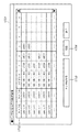
センサ制御マスタ300を構成する各要素について、図4を参照して更に説明する。図4はセンサ制御マスタ300にデータが設定されている様子を例示的に示した図である。
Each element constituting the
図4では、センサNo301がs0001、s0002、s0003の3つのセンサ101について制御設定303が定義されている。センサs0001、s0002、s0003がイベントを検出すると、それぞれ最大3台、1台、2台のカメラ102が動作し得る。以下、あるセンサ101がイベントを検出した時にあるカメラ102の動作が制御され得る場合、そのセンサ101とカメラ102とは関連づけられていると呼ぶ。例えば、センサs0001と、カメラc0001、c0002、c0003とは関連づけられている。また、センサs0002とカメラc0001、センサs0003とカメラc0001、c0002は関連づけられている。
In FIG. 4,
ここでは、一例としてセンサs0003について定義されている内容について説明する。センサs0003には、カメラc0001とc0002が関連づけられている。即ち、センサs0003がイベントを検出すると、カメラc0001とc0002との動作が制御され得る。センサs0003に関して、カメラc0001にはTELE優先序列307として1が、カメラc0002にはTELE優先序列307として2が割り当てられており、カメラc0001が優先的にTELE側に動作制御される。但し、実際にそれぞれのカメラ102がどのように動作制御されるかは、他のセンサ101の状況や、カメラ102の動作状況等により決定される。この動作決定のアルゴリズムについては後述する。
Here, contents defined for the sensor s0003 will be described as an example. Cameras c0001 and c0002 are associated with the sensor s0003. That is, when the sensor s0003 detects an event, the operations of the cameras c0001 and c0002 can be controlled. Regarding the sensor s0003, 1 is assigned to the camera c0001 as the
センサs0003について、カメラc0001のTELE側PTZ値及びWIDE側PTZ値はそれぞれ(パン(Pan),チルト(Tilt),ズーム(Zoom))=(85,−5,12)、(85,−5,1)である。カメラc0002のTELE側PTZ値及びWIDE側PTZ値はそれぞれ(パン,チルト,ズーム)=(−55,−25,10)、(−55,−25,1.5)である。ここで、パン及びチルトの値は、例えば基準位置からの回転角である。また、ズーム値は、例えば基準値に対する倍率である。 For the sensor s0003, the TELE side PTZ value and the WIDE side PTZ value of the camera c0001 are (Pan, Tilt, Zoom) = (85, -5, 12), (85, -5, respectively). 1). The TELE side PTZ value and the WIDE side PTZ value of the camera c0002 are (pan, tilt, zoom) = (− 55, −25, 10) and (−55, −25, 1.5), respectively. Here, the pan and tilt values are, for example, rotation angles from the reference position. The zoom value is a magnification with respect to a reference value, for example.
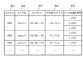
図5は、ネットワークカメラ管理マスタ500の内容を模式的に示した図である。ネットワークカメラ管理マスタ500は、監視カメラシステムに接続されたカメラ102毎にそのIPアドレスや、平常時の動作設定、複数のセンサ101がイベントを検出した場合に、どのセンサイベント信号に基づいて動作を制御するかを定義している。
FIG. 5 is a diagram schematically showing the contents of the network
図5において、501はカメラ102のID(カメラID)でありカメラの識別子として用いられる。502はそのカメラ102に割り当てられた名前(カメラ名)であり、503は、カメラ102のIPアドレスである。504は、カメラ102の平常時の動作設定であり、平常時パン(Pan)値、平常時チルト(Tilt)値、平常時ズーム(Zoom)値(以下、これらをまとめて平常時PTZ値と略記する)から構成される。505は、複数のセンサイベント信号が入力された場合にどのセンサイベント信号に基づいて動作を制御するかを定義しているセンサNo優先序列であり、カメラ102に関連づけられている全てのセンサ101に優先順位が割り当てられている。
In FIG. 5,
本実施形態においては、同時期に2以上のセンサ101がイベントを検出し、イベントを検出したセンサ101に対応するカメラ102が互いに重複する場合、センサNo優先序列505に基づいて、どのセンサイベント信号に基づいて動作を制御するかが決定される。
In the present embodiment, when two or
ネットワークカメラ管理マスタ500を構成する各要素について、図6を参照して更に説明する。図6はネットワークカメラ管理マスタ500にデータが設定されている様子を例示的に示した図である。 図6では、カメラID501がc0001、c0002、c0003の3つのカメラ102について値の設定がなされている。カメラID501がc0001、c0002、c0003のカメラ102は、それぞれカメラ名502がcamera−1、camera−2、camera−3を有しており、それぞれのIPアドレス503は192.168.1.101、192.168.1.102、192.168.1.103である。また、平常時PTZ値504は、それぞれ(パン,チルト,ズーム)=(−10,−10,5)、(70,−15,6)、(30,−15,5)である。
Each element constituting the network
また、カメラc0002に着目すると、センサNo優先序列505としてセンサs0001とセンサ0003とに値が割り当てられている。これは、図4よりカメラc0002はセンサs0001及びs0003に関連づけられているため、同時期にセンサs0001とs0003とがイベントを検出した場合に、どちらに基づいて動作を決定するかを定めたものである。図4の例では、カメラc0002について、センサs0001に1、センサs0003に2が割り当てられているため、カメラc0002はセンサs0001のイベント検出に基づいて優先的に動作する。但し、実際にカメラ102がどのように動作制御されるかは、カメラ102の動作状況等により決定される。この動作決定のアルゴリズムについては後述する。
Further, focusing on the camera c0002, values are assigned to the sensors s0001 and 0003 as the sensor
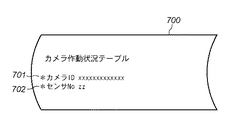
図7は、カメラ作動状況テーブル700の内容を模式的に示した図である。カメラ作動状況テーブル700は、監視カメラシステムを構成する全てのカメラ102についてその動作状況を管理している。図7において、カメラID701はカメラのIDである。センサNo702は、カメラID701で識別されるカメラ102がセンサイベント信号に基づいて動作制御されている場合はそのセンサ101のIDを保持し、センサイベント信号に基づいて動作していない場合、即ち、平常時は値「N」を保持する。
FIG. 7 is a diagram schematically showing the contents of the camera operation status table 700. The camera operation status table 700 manages the operation status of all
図8は、カメラ作動状況テーブル700にデータが設定されている様子を例示的に示した図である。図8では、カメラc0001がセンサs0002に、カメラc0003がセンサs0001に基づいて動作している。カメラc0002の動作はどのセンサイベント信号にも基づいておらず、平常時の動作を行っている。なお、カメラ作動状況テーブル700のセンサNo702は、全てのカメラID701について値「N」に初期化される。
FIG. 8 is a diagram exemplarily showing that data is set in the camera operation status table 700. In FIG. 8, the camera c0001 operates based on the sensor s0002, and the camera c0003 operates based on the sensor s0001. The operation of the camera c0002 is not based on any sensor event signal, and performs a normal operation. Note that sensor No. 702 in the camera operation status table 700 is initialized to a value “N” for all
(監視制御処理)
次に、センサ101がイベントを検出した場合に、サーバ100が行うカメラ102の動作制御処理について説明する。図9は、サーバ100が処理を開始してから終了するまでの、監視カメラシステム全体の処理の流れを示したフローチャートである。
(Monitoring control processing)
Next, an operation control process of the
図9において、サーバ100は処理を開始すると、1以上のカメラ102に対してコントロール情報を送出する(901)。コントロール情報には、パン、チルト、ズーム値(以下、PTZ値と呼ぶ)等の、平常時のカメラ102の動作を制御する情報が含まれている。コントロール情報を受け取ったカメラ102は受け取り確認のための応答をサーバ100へ返す(902)。
In FIG. 9, when the
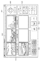
カメラ102における撮像を開始する場合は、サーバ100は撮影要求をカメラ102へ送出する(903)。カメラ102は、撮影要求を受信すると撮影を開始し、撮像して得られた撮像データをサーバ100へ送出する(904)。撮像データとは、CCDの撮影画像を例えばJPEGやMPEG形式に変換したものである。撮像データの送出は、サーバ100から終了の指示がない限り継続して行われる。尚、901〜903の通信は、例えば、TCPプロトコルを用いて行い、904の通信は、例えばUDPプロトコルを用いて行う。サーバ100はカメラ102より受け取った撮像データを、ユーザが映像を容易に理解できるようなユーザインタフェースによって、CRT210に表示制御する。図10は、そのようなユーザインタフェースを例示的に示した図である。ユーザインタフェースのウィンドウ1001において、監視領域104毎にタブ1002を用意して、ユーザが監視領域104を容易に選択可能にしている。ユーザにより選択された監視領域104については、例えば、優先度に応じて様々なサイズのビデオ表示域1003を設け、ユーザが一見して映像を把握できるようにする。なお、センサ101のイベント検出の履歴を表示する表示域1004を設け、センサ101のイベント検出に基づいて撮像され、記憶制御した映像を時系列に沿って容易に選択し、再生できるようにしている。
When imaging with the
図9の説明に戻る。サーバ100は起動中、センサ101からのセンサイベント信号の有無を監視している。センサ101からセンサイベント信号が入力された場合、即ち、センサイベントが発生した場合(ステップS951でYES)、センサ制御マスタ300、及び、ネットワークカメラ管理マスタ500の設定に基づいてカメラ102に送出すべき所定のコントロール情報を決定する(ステップS952)。そして、決定したコントロール情報をカメラ102へ送出する(905)。カメラ102は、コントロール情報を受け取ると、その内容に基づいて動作を制御し、受け取り確認のための応答をサーバ100へ返す(906)。なお、撮像データの送出は継続して行われ、サーバ100はこの撮像データ(映像信号)を外部メモリ216等の記憶装置に記憶制御する(907)。
Returning to the description of FIG. During startup, the
一定時間が経過した等、イベント検出時撮像終了イベントが発生した場合(ステップS953でYES)、サーバ100は平常時の動作設定を含むコントロール情報をカメラ102へ送出し、カメラの動作を平常時に復帰させる(908)。カメラ102は応答情報を返し(909)、引き続き撮像データの送出を継続する(910)。
If an imaging end event occurs when an event is detected (eg, YES in step S953) such as when a certain period of time has elapsed, the
監視カメラシステムの処理はおおむね901〜910の流れに基づいてなされる。処理を終了する場合、サーバ100はカメラ102へ、処理を終了する旨を示す終了通知を送信する(912)。カメラ102は、終了通知を受け取ると、受け取り確認のための終了応答をサーバ100へ返し(913)、処理を終了する。サーバ100は、終了応答を受け取ったことを確認し、処理を終了する。尚、本実施形態においては、どのセンサ101もイベントを検出していない場合、即ち、平常時においてはサーバ100は撮像データを一定時間記録した後は削除するものとする。但し、実施形態によっては平常時に受信した撮像データを全て記憶制御するような構成にしてもよい。
The processing of the surveillance camera system is generally performed based on the flow of 901 to 910. When the process is to be ended, the
次に、センサ101がイベントを検出した場合におけるサーバ100の処理について、図11を参照して説明する。図11は、センサイベント信号を受信した場合のサーバ100の処理を示すフローチャートである。先に述べたように、サーバ100は起動中、センサ101からのセンサイベント信号の有無を監視している。これを図11ではステップS1101で示す。センサイベントが発生した場合(ステップS1101でYES)、ステップS1102へ進み、イベントを検出したセンサ101のIDを取得する。
Next, processing of the
次に、ステップS1103において、サーバ100はセンサNoをキーとしてセンサ制御マスタ300を検索し、イベントを発したセンサ101に対応する制御カメラ数及び制御設定(カメラIDを含む)を取得する。そして、ステップS1104において、ステップS1103で取得したカメラIDをキーとしてネットワークカメラ管理マスタ500を検索し、カメラ102のIPアドレスとセンサNo優先序列505を取得する。この処理はステップS1103で取得した全てのカメラIDについて行う。ステップS1103〜ステップS1104で取得した情報に基づいて、新たにコントロール情報を送出するカメラ102の候補が特定される。
Next, in step S1103, the
これ以降の処理では、センサ制御マスタ300を検索して得られた全てのカメラ102について、TELE優先序列307やセンサNo優先序列505等の関連情報に基づいてその動作を決定する。
In the subsequent processing, the operation of all the
ステップS1105において、RAM202等のメモリの領域を確保し、整数値のカウンタを1で初期化する。また、ブール値のTELEフラグを0で初期化する。また、整数値の実行カメラ数を0で初期化する。但し、カウンタはその値がTELE優先序列307に対応づけられており、ステップS1103で得られた制御設定303に記憶されているカメラIDを識別する。TELEフラグはTELE側に設定されているカメラ102の有無を保持する2値フラグであり、1がTELE側のカメラあり、0がTELE側のカメラなし、を意味する。実行カメラ数は、センサ101のイベント検出に基づいて動作を制御可能なカメラ102の数であり、センサNo優先序列505や機器の故障等により動作を制御できないカメラ102はカウントされない。
In step S1105, a memory area such as the
次に、ステップS1106からステップS1117にかけてループ(繰り返し)処理を実行する。ループ処理の終了条件はカウンタ>制御カメラ数が成り立つことである(ステップS1106)。尚、前述したように、カウンタはその値がTELE優先序列307に対応づけられているため、ループ処理においてはTELE優先序列307の高いカメラから順に評価されることに留意する。
Next, a loop (repetition) process is executed from step S1106 to step S1117. The loop processing end condition is that counter> the number of control cameras is satisfied (step S1106). Note that, as described above, since the counter value is associated with the
まず、ステップS1107において、カウンタの値に対応するカメラ102と所定の通信を行い、そのカメラ102が正常動作を行っているか否かをカメラ102からの応答で判定する。正常動作を行っていない場合(ステップS1107でNO)はステップS1113へ進み、カメラ作動状況テーブル700の、このカメラ102のセンサNo702の値を「N」に設定する。そして、ステップS1117へ進み、カウンタの値を1増加させてステップS1106へ戻る。ステップS1107においてカメラ102が正常動作を行っていると判定された場合(ステップS1107でYES)は、ステップS1108へ進む。
First, in step S1107, predetermined communication is performed with the
ステップS1108においては、カウンタに対応するカメラ102が現にイベント検出時撮像を行っているか否かを判定する。イベント検出時撮像を行っている場合(ステップS1108でYES)はステップS1109へ進み、イベント検出時撮像を行っていない場合(ステップS1108でNO)はステップS1110へ進む。
In step S1108, it is determined whether or not the
ステップS1109においては、カウンタに対応するカメラ102のセンサNo優先序列505を参照し、カウンタに対応するカメラ102をイベント検出時撮像の状態にしているセンサ101のセンサNo優先序列505とステップS1101においてイベントを検出したセンサ101のセンサNo優先序列505とを比較する。ステップS1101においてイベントを検出したセンサ101の方が、カウンタに対応するカメラ102をイベント検出時撮像の状態にしているセンサ101よりも、優先序列が高い(即ち、センサNo優先序列505の値が小さい)場合(ステップS1109でYES)は、ステップS1110へ進む。そうでない場合(ステップS1109でNO)ステップS1110〜S1116の処理をスキップしてステップS1117へ進む。以上の、ステップS1107〜S1109の各工程によって、新たにコントロール情報を送出するカメラ102が決定されている。
In step S1109, the sensor
ステップS1110〜ステップS1116においては、カウンタに対応するカメラ102の動作をセンサ制御マスタ300に定義されている設定内容で動作制御する処理を行う。ステップS1110では、実行カメラ数の値を1増加する。次に、ステップS1111へ進み、カメラ作動状況テーブル700におけるカウンタに対応するカメラ102について、センサNo702の値をステップS1101においてイベントを検出したセンサ101のセンサNoに設定する。
In steps S <b> 1110 to S <b> 1116, processing is performed to control the operation of the
次に、ステップS1112へ進み、TELEフラグの値が0であるか否か、即ち、TELE側に設定されているカメラ102が存在するか否かを判定する。TELE側に設定されているカメラ102が存在しない場合(ステップS1112でYES)はステップS1114へ進み、存在する場合(ステップS1112でNO)はステップS1115へ進む。
Next, the process proceeds to step S1112, and it is determined whether or not the value of the TELE flag is 0, that is, whether or not the
ステップS1114においては、カウンタに対応するカメラ102へTELE側PTZ値305を送信して、そのカメラ102をTELE側の動作に設定する。そして、ステップS1116においてTELEフラグに1を設定し、ステップS1117へ進む。
In step S1114, the TELE
ステップS1115においては、カウンタに対応するカメラ102へWIDE側PTZ値305を送信して、そのカメラ102をWIDE側の動作に設定する。尚、先に述べたように、ループ処理においてはTELE優先序列307の高いカメラから順に評価されるため、ステップS1115の処理が評価される場合には、よりTELE優先序列307の高いカメラ102がTELE側に設定されていることに留意する。ステップS1115の処理が終了するとステップS1117へ進む。
In step S1115, the WIDE
以上、ステップS1106からステップS1117の処理を、イベントを検出したセンサ101に関連づけられている全てのカメラ102について繰り返し実行する。そして、ステップS1118へ進む。
As described above, the processing from step S1106 to step S1117 is repeatedly executed for all the
ステップS1118においては、実行カメラ数の値が1であるか否かを判定する。1である場合(ステップS1118でYES)はステップS1119へ進み、1ではない場合(ステップS1118でNO)はステップS1120へ進む。 In step S1118, it is determined whether the value of the execution camera number is 1. If it is 1 (YES in step S1118), the process proceeds to step S1119. If it is not 1 (NO in step S1118), the process proceeds to step S1120.
本実施形態では、ステップS1101でイベントを検出したセンサ101に関連づけられたカメラのうち、制御可能なカメラ102が1台の場合はそのカメラ102を、より撮影領域の広いWIDE側に設定するものとする。ステップS1119においては、制御可能なカメラ102へWIDE側PTZ値305を送信して、そのカメラ102をWIDE側の動作に設定する。そして、ステップS1120へ進む。
In the present embodiment, when there is one
ステップS1120においては、各カメラ102より送出される撮像データをセンサ101が検出したイベントと関連づけて、カメラ102毎に外部メモリ216等の記憶装置に記憶制御する。尚、センサ101がイベントを検出した時点から遡って一定時間前の時点からの撮像データをも記憶制御するようにしてもよい。
In step S1120, image data transmitted from each
イベント検出時撮像を終了するイベントは予めカメラ102毎又はサーバ100に設定されているものとし、あるカメラ102又はサーバ100についてイベント検出時撮像終了イベントが発生した場合(ステップS1121でYES)は、ステップS1122へ進む。ステップS1122においては、イベント検出時撮像終了イベントが発生したカメラ102に対してネットワークカメラ管理マスタ500に記録されている平常時の動作設定を送出し、平常時の動作に復帰するよう制御する。また、サーバ102はそのカメラ102から送られてくる撮像データの記憶制御を終了する。更にカメラ作動状況テーブル700のセンサNO702について該当カメラ701と対のセンサNOに“N”を代入する。この処理は、センサによるカメラ占有制御が終了した事を記録するためのものである。尚、イベント検出時撮像を終了するイベントは、例えば、録画開始からの一定時間経過等である。
It is assumed that the event for ending the imaging at the time of event detection is set in advance for each
以上のように、センサ101毎にカメラ102の動作を定義したセンサ制御マスタ300を用意し、センサ101がイベントを検出したときに、センサ制御マスタ300の値に基づいてカメラ102の動作を制御することで、複数のカメラ102を用いて映像を撮影することを可能にしている。また、センサ制御マスタ300が、制御設定303がTELE側PTZ値305、WIDE側PTZ値306、及び、TELE優先序列307を含むようにし、TELE優先序列307に基づいてカメラ102の動作を制御することで、状況に合わせて複数の監視カメラの動作を関連づけ、全体として適切な映像を撮影することを可能にしている。具体的には、例えば、詳細な映像を取得するために1台のカメラ102をTELE側に設定しつつ、監視領域104の全体像を見渡すためにそれ以外のカメラ102をWIDE側に設定するといった制御を行うことができる。
As described above, the
更に、カメラ毎にセンサNo優先序列505を定義したネットワークカメラ管理マスタ500を用意し、複数のセンサ102が同時期にイベントを検出した場合にはセンサNo優先序列505に基づいてカメラ102の動作を制御することで、複雑な条件においても複数のカメラ102を用いて全体として適切な映像を撮影することを可能にしている。
Further, a network
尚、本実施形態においては、あるセンサ101がイベントを検出した場合、そのカメラに関連づけられたカメラ102のうち、1台をTELE側に設定し、残りをWIDE側に設定する構成について述べたが、本発明に係る実施形態はこれに限られるものではない。例えば、1台をWIDE側に設定し、残りをTELE側に設定する構成としてもよい。
In the present embodiment, when a
また、センサ制御マスタ300の制御設定を拡張して、TELE側、WIDE側の設定のみならず、例えば、ある軌道を周回して撮影する設定や、ズームインとズームアウトを繰り返すような設定をも可能にし、各カメラ102に動作の優先度を設定して、全体として適した映像が得られる構成としてもよい。
In addition, the control settings of the
<<第2実施形態>>
第1実施形態においては、センサ制御マスタ等のカメラの動作を定義したテーブルには予め値が設定されている場合の動作について説明した。本実施形態においては、ユーザが容易にカメラの動作設定することを可能にする構成について説明する。システム構成、サーバの構成、データの構成は第1実施形態と同様である。尚、センサ制御マスタ300へのセンサNo301の登録と、ネットワークカメラ管理マスタ500へのカメラID501、カメラ名502、IPアドレス503の登録はすでになされているものとする。
<< Second Embodiment >>
In the first embodiment, the operation when values are set in advance in the table defining the operation of the camera such as the sensor control master has been described. In the present embodiment, a configuration that allows the user to easily set the operation of the camera will be described. The system configuration, server configuration, and data configuration are the same as in the first embodiment. It is assumed that registration of sensor No. 301 to the
(動作設定処理)
図12は、サーバ100がカメラの動作設定を行う処理のフローチャートである。まず、ステップS1201において、サーバ100は図15に例示するようなカメラの動作設定・管理画面(以下、動作設定画面と呼ぶ)を表示制御し、ステップS1202へ進む。図15は、カメラの動作設定画面を例示的に示した図である。
(Operation setting process)
FIG. 12 is a flowchart of processing in which the
図15において、1501は動作設定画面のウィンドウであり、撮像データ表示域1502、TELE優先度設定領域1504、カメラコントロール領域1505、カメラ設定領域1506等を含んでいる。カメラ設定領域1506には、センサを選択して呼び出す入力インタフェース(以下、センサ選択I/Fと呼ぶ)と、カメラにTELE側及びWIDE側の座標を適用する入力インタフェース(以下、TW適用I/Fと呼ぶ)が含まれている。カメラコントロール域1505はユーザがPTZ値を容易に設定することのできる入力インタフェース(PTZ設定I/Fと呼ぶ)を含んでいる。ビデオ表示域1502には、センサ選択I/Fにより選択されたセンサ101に関連づけられたカメラ102が撮像し、サーバ100へ送っている撮像データのサムネールを一覧表示している。また、サムネールの近傍にカメラ102に割り当てられているTELE優先序列307を表示している。
In FIG. 15,
ユーザによりポインティングデバイス等でサムネールが選択されると、サーバ100は選択されたサムネールを1503のように強調表示され、更にサムネイル部分は動画表示される。この時、ユーザによりPTZ設定I/Fを操作されると、サーバ100はユーザの操作に基づいてPTZ値を計算し、選択された動画1503を送出しているカメラ102へ送り、カメラ102の撮像条件を更新する。PTZ値はカメラ設定領域1506の下部に表示制御する。撮像条件が更新された後もカメラ102は撮像データをサーバ100へ送り続け、サーバ100はその内容を継続して撮像データ表示域1502に表示制御する。これにより、ユーザはリモコンを操作するように容易にカメラ102の撮像条件を設定することができる。また、1503のように、あるビデオのサムネールが選択されている状態でTW適用I/Fが操作されると、サーバ100は対応するカメラ102について、TELE側PTZ値305、又は、WIDE側PTZ値306を、ビデオ表示域1502に表示されている撮像条件で設定する。
When the user selects a thumbnail with a pointing device or the like, the
また、ユーザによりサムネールがTELE優先度設定領域1504にドラッグ・アンド・ドロップされると、サーバ100は、サムネールに対応するカメラ102のTELE優先序列307をドロップされたTELE優先度の値に設定する。以上のような設定が行われた後、DB登録ボタン1507が選択されると、サーバ100は、設定された値に基づいてセンサ制御マスタ300及びネットワークカメラ管理マスタ500の値を更新する。 図12の説明に戻る。ステップS1202において、ユーザによりセンサ選択I/FからセンサNoが入力されるとステップS1203へ進む。ステップS1203においては、センサ制御マスタ300を検索し、入力されたセンサNoに対応するデータがすでに存在するか、即ち、新規入力であるか否かを判定する。新規入力の場合(ステップS1203でYES)はステップS1206へ進み、新規入力ではない場合(ステップS1203でNO)はステップS1204へ進む。
When the user drags and drops a thumbnail into the TELE
ステップS1204においては、入力されたセンサNoをキーとしてセンサ制御マスタ300を検索し、選択されたセンサ101に関連づけられた全てのカメラ102の制御設定303の値を抽出する。続けて、ステップS1205において、選択されたセンサ101に関連づけられた全てのカメラ102について、カメラIDをキーとしてネットワークカメラ管理マスタ500を検索し、カメラ102のIPアドレスやセンサNo優先序列505等の情報を取得する。そして、ステップS1207へ進む。
In step S1204, the
ステップS1206においては、センサNoで識別されるセンサ101にカメラ102の関連づけを行う処理を行う。この処理の詳細を図13のフローチャートに示す。また、ステップS1206の処理、即ち、図13に示す処理を行う際に、サーバ100は図16に示す新規カメラマーキング画面(以下、マーキング画面と呼ぶ)を表示制御する。
In step S1206, processing for associating the
図16において、1601はマーキング画面のウィンドウであり、カメラ一覧表示領域1602、登録カメラ取得ボタン1603、登録ボタン1604等を含んでいる。ユーザにより登録カメラ取得ボタン1603が押下されると、サーバ100はネットワークカメラ管理マスタ500を参照し、登録されている全カメラの情報をカメラ一覧表示領域1602に表示制御する。この処理は図13のステップS1301に相当する。
In FIG. 16,
カメラ一覧表示領域1602において、「使用」欄はステップS1202で入力されたセンサNoで識別されるセンサ101に、カメラ102が関連づけられているか否かを表示している。図16の例では、カメラc0002が関連づけられている。サーバ100はユーザが使用欄に直接入力することでカメラ102の関連づけ(マーキング)を容易に行えるようにしている。マーキングの処理は図13のステップS1302に相当する。
In the camera
マーキング後、ユーザにより登録ボタン1604が押下されると、サーバ100は入力されたマーキングの情報に基づいてセンサ制御マスタ300の値を更新する。この処理はステップS1303に相当する。この後、図12のステップS1207へ進む。
When the
図12の説明に戻る。ステップS1207においては、この前の処理において取得、又は、設定されたカメラ動作設定の値に基づいて各カメラ102にコントロール情報及び撮像要求を送出する。各カメラ102は受け取った情報に基づいて撮像条件を設定し、撮像を行い、撮像データをサーバ100へ送信する。サーバ100は受信した撮像データに基づいて、図15に例示したような動作設定画面を表示制御する。
Returning to the description of FIG. In step S1207, control information and an imaging request are transmitted to each
先に述べたように、サーバ100はこの画面を介して各カメラ102のPTZ値を設定可能に制御している。この処理(ステップS1208に相当する)の詳細を図14に示す。先に述べたように、ユーザは撮像データのサムネールを選択後、PTZ設定I/Fを用いてそのサムネールを撮像しているカメラ102のPTZ値を更新することができる。この処理はステップS1402に相当する。また、サーバ100は更新されたPTZ値をカメラ102へ送信し、更新された撮像条件に基づいて撮像されたビデオを動作設定画面に表示制御する。この処理はステップS1403に相当する。サーバ100は、ユーザによる設定が終了するまでステップS1401〜S1404の処理を繰り返す。ユーザによる設定が終了したら(例えば、不図示の設定終了ボタンが押下された場合)ステップS1209へ進む。尚、ユーザによる設定は、先に述べたTELE優先度設定領域1504を用いたTELE優先序列307の設定等も含まれる。
As described above, the
図12の説明に戻る。ステップS1209においては、ユーザにより設定されたPTZ値、TELE優先序列307等の値をセンサ制御マスタ300に設定する。尚、この処理は、例えば、ユーザによりDB登録ボタン1507が押下されたタイミングでなされるものとする。
Returning to the description of FIG. In step S1209, values such as the PTZ value and
次に、ステップS1210において、図17に例示するセンサNo優先序列設定画面を表示制御してユーザがカメラ毎のセンサNo優先序列505を設定可能にする処理を行う。図17において、1701はセンサNo優先序列設定画面のウィンドウであり、カメラ一覧表示領域1702、センサNo取得ボタン1703、登録ボタン1704を含んでいる。
Next, in step S1210, the sensor No priority order setting screen illustrated in FIG. 17 is displayed and controlled so that the user can set the sensor No
ユーザによりセンサNo取得ボタン1703が選択されると、サーバ100は全てのカメラ102のIDをキーとしてネットワークカメラ管理マスタ500を参照し、カメラIDに対応するカメラ名、IPアドレス、センサNo優先序列505を取得し、カメラ一覧表示領域1702に表示制御する。サーバ100は、この表示制御の後、同一行に表示制御しているセンサNo優先序列505の値について、ユーザによるドラッグ・アンド・ドロップにより交換可能に制御する。この処理により、ユーザは容易にセンサNo優先序列505を設定することができる。ユーザによる所望の設定後、登録ボタン1704が選択されると、サーバ100は設定された値をネットワークカメラ管理マスタ500に設定する。
When the sensor
次に、ステップS1211において、ユーザにより不図示の設定終了ボタンが選択されたか否かを判定し、設定終了ボタンが選択された場合(ステップS1211でYES)は処理を終了する。選択されていない場合(ステップS1211でNO)はステップS1202へ戻り、さらに設定可能に制御する。 Next, in step S1211, it is determined whether or not a setting end button (not shown) is selected by the user. If the setting end button is selected (YES in step S1211), the process ends. If it is not selected (NO in step S1211), the process returns to step S1202, and is further controlled so as to be settable.
以上のように、ドラッグ・アンド・ドロップを基本とした動作設定画面を提供することにより、ユーザは容易に各カメラ102の動作を設定することができる。
As described above, by providing an operation setting screen based on drag and drop, the user can easily set the operation of each
<<その他の実施形態>>
以上、本発明の実施形態例について詳述したが、本発明は、例えば、システム、装置、方法、プログラムもしくは記憶媒体等としての実施態様を取ることが可能であり、具体的には、複数の機器から構成されるシステムに適用しても良いし、また、一つの機器からなる装置に適用しても良い。
<< Other Embodiments >>
As described above, the exemplary embodiments of the present invention have been described in detail. However, the present invention can take an embodiment as, for example, a system, an apparatus, a method, a program, or a storage medium. You may apply to the system comprised from an apparatus, and may apply to the apparatus which consists of one apparatus.
尚、本発明は、前述した実施形態の機能を実現するプログラムを、システムあるいは装置に直接あるいは遠隔から供給し、そのシステムあるいは装置のコンピュータが該供給されたプログラムコードを読み出して実行することによっても達成される場合を含む。 The present invention can also be achieved by supplying a program that realizes the functions of the above-described embodiment directly or remotely to a system or apparatus, and the computer of the system or apparatus reads and executes the supplied program code. Including the case where it is achieved.
従って、本発明の機能処理をコンピュータで実現するために、該コンピュータにインストールされるプログラムコード自体も本発明の技術的範囲に含まれる。つまり、本発明は、本発明の機能処理を実現するためのコンピュータプログラム自体も含む。 Therefore, since the functions of the present invention are implemented by a computer, the program code installed in the computer is also included in the technical scope of the present invention. That is, the present invention includes a computer program itself for realizing the functional processing of the present invention.
その場合、プログラムの機能を有していれば、オブジェクトコード、インタプリタにより実行されるプログラム、OSに供給するスクリプトデータ等の形態であっても良い。 In that case, as long as it has the function of a program, it may be in the form of object code, a program executed by an interpreter, script data supplied to the OS, or the like.
プログラムを供給するための記録媒体としては、例えば、フロッピー(登録商標)ディスク、ハードディスク、光ディスク、光磁気ディスク、MO、CD−ROM、CD−R、CD−RW、磁気テープ、不揮発性のメモリカード、ROM、DVD(DVD−ROM,DVD−R)などがある。 As a recording medium for supplying the program, for example, floppy (registered trademark) disk, hard disk, optical disk, magneto-optical disk, MO, CD-ROM, CD-R, CD-RW, magnetic tape, nonvolatile memory card ROM, DVD (DVD-ROM, DVD-R) and the like.
その他、プログラムの供給方法としては、クライアントコンピュータのブラウザを用いてインターネットのホームページに接続し、該ホームページから本発明のコンピュータプログラムそのもの、もしくは圧縮され自動インストール機能を含むファイルをハードディスク等の記録媒体にダウンロードすることによっても供給できる。また、本発明のプログラムを構成するプログラムコードを複数のファイルに分割し、それぞれのファイルを異なるホームページからダウンロードすることによっても実現可能である。つまり、本発明の機能処理をコンピュータで実現するためのプログラムファイルを複数のユーザに対してダウンロードさせるWWWサーバも、本発明に含まれるものである。 As another program supply method, a client computer browser is used to connect to an Internet homepage, and the computer program of the present invention itself or a compressed file including an automatic installation function is downloaded from the homepage to a recording medium such as a hard disk. Can also be supplied. It can also be realized by dividing the program code constituting the program of the present invention into a plurality of files and downloading each file from a different homepage. That is, the present invention includes a WWW server that allows a plurality of users to download a program file for realizing the functional processing of the present invention on a computer.
また、本発明のプログラムを暗号化してCD−ROM等の記憶媒体に格納してユーザに配布し、所定の条件をクリアしたユーザに対し、インターネットを介してホームページから暗号化を解く鍵情報をダウンロードさせ、その鍵情報を使用することにより暗号化されたプログラムを実行してコンピュータにインストールさせて実現することも可能である。 In addition, the program of the present invention is encrypted, stored in a storage medium such as a CD-ROM, distributed to users, and key information for decryption is downloaded from a homepage via the Internet to users who have cleared predetermined conditions. It is also possible to execute the encrypted program by using the key information and install the program on a computer.
また、コンピュータが、読み出したプログラムを実行することによって、前述した実施形態の機能が実現される他、そのプログラムの指示に基づき、コンピュータ上で稼動しているOSなどが、実際の処理の一部または全部を行ない、その処理によっても前述した実施形態の機能が実現され得る。 In addition to the functions of the above-described embodiments being realized by the computer executing the read program, the OS running on the computer based on an instruction of the program is a part of the actual processing. Alternatively, the functions of the above-described embodiment can be realized by performing all of them and performing the processing.
さらに、記録媒体から読み出されたプログラムが、コンピュータに挿入された機能拡張ボードやコンピュータに接続された機能拡張ユニットに備わるメモリに書き込まれた後、そのプログラムの指示に基づき、その機能拡張ボードや機能拡張ユニットに備わるCPUなどが実際の処理の一部または全部を行ない、その処理によっても前述した実施形態の機能が実現される。 Furthermore, after the program read from the recording medium is written to a memory provided in a function expansion board inserted into the computer or a function expansion unit connected to the computer, the function expansion board or The CPU or the like provided in the function expansion unit performs part or all of the actual processing, and the functions of the above-described embodiments are also realized by the processing.
Claims (6)
前記複数の検知装置に個別に割り当てられた検知装置識別情報の各々に対して、対応する複数の撮像装置の識別情報と、当該複数の撮像装置の優先順位情報とを設けた第1の管理情報を記憶する第1の記憶手段と、
前記複数の検知装置の1つが前記イベント情報を検知した場合に、当該イベント情報を検知した検知装置の検知装置識別情報を受信する受信手段と、
前記第1の管理情報に基づいて、前記受信した前記検知装置識別情報と対応付けられた複数の撮像装置を選定する第1の選定手段と、
前記第1の選定手段が選定した前記複数の撮像装置の中から、前記第1の管理情報の優先順位情報に基づいて1つの撮像装置を選定する第2の選定手段と、
前記複数の撮像装置に個別に割り当てられた撮像装置識別情報の各々に対して、対応する複数の検知装置の検知装置識別情報と、当該複数の検知装置の優先順位情報とを設けた第2の管理情報を記憶する第2の記憶手段と、
前記受信手段が受信した検知装置識別情報に対応付けられた第1の検知装置と、前記第2の管理情報において前記1つの撮像装置に対応付けられた第2の検知装置との優先順位を、前記第2の管理情報の優先順位情報に基づいて判断する第1の判断手段と、
前記第1の判断手段が、前記第1の検知装置の優先順位が高いと判断した場合に、前記1つの撮像装置を、前記第1の検知装置のイベント情報に対応した制御設定で制御させる第1の撮像装置として指定する指定手段と、
を備えることを特徴とする情報処理装置。 An information processing apparatus connected to a plurality of detection devices that detect event information and a plurality of imaging devices that capture an image,
First management information provided with identification information of a plurality of corresponding imaging devices and priority information of the plurality of imaging devices for each of the detection device identification information individually assigned to the plurality of detection devices. First storage means for storing
When the one of the plurality of sensing devices, but it detects the event information, the receiving unit that will receive detection device identification information of the detecting device detects the event information,
Based on the first management information, a first selection constant means for selecting a plurality of imaging devices that is associated with said received the detection device identification information,
Second selection means for selecting one imaging device based on priority information of the first management information from among the plurality of imaging devices selected by the first selection means;
A second set of detection device identification information of a plurality of corresponding detection devices and priority order information of the plurality of detection devices is provided for each of the imaging device identification information individually assigned to the plurality of imaging devices. Second storage means for storing management information;
The priority order of the first detection device associated with the detection device identification information received by the reception unit and the second detection device associated with the one imaging device in the second management information, First determination means for determining based on priority information of the second management information;
When the first determination unit determines that the priority order of the first detection device is high, the first image pickup device is controlled with a control setting corresponding to the event information of the first detection device. Designation means for designating as one imaging device ;
An information processing apparatus comprising:
前記指定手段が指定した回数を計数する計数手段と、
前記第1の選定手段が選定した前記複数の撮像装置の数と、前記計数手段が計数した回数とを比較して大小を判断する第2の判断手段と、
を更に備え、
前記第2の選定手段は、前記第2の判断手段が前記第1の選定手段が選定した前記複数の撮像装置の数の方が多いと判断した場合に、前記第1の管理手段の優先順位情報に基づいて前記第1の撮像装置の次に優先される撮像装置を選定すること特徴とする請求項1に記載の情報処理装置。 The information processing apparatus includes:
Counting means for counting the number of times designated by the designation means;
A second judging means for judging the size by comparing the number of the plurality of imaging devices selected by the first selecting means with the number of times counted by the counting means;
Further comprising
The second selection unit determines the priority of the first management unit when the second determination unit determines that the number of the plurality of imaging devices selected by the first selection unit is larger. The information processing apparatus according to claim 1, wherein an imaging apparatus that is prioritized next to the first imaging apparatus is selected based on information.
前記イベント情報に基づいて、個別の撮像装置がイベント動作中か否かを管理する第3の管理情報を記憶する第3の記憶手段と、
前記第3の管理情報に基づいて、前記第2の選定手段が選定した前記1つの撮像装置がイベント動作中か否かを判断する第3の判断手段と、
前記第2の検知装置を指定する第2の指定手段と、
を更に備え、
第2の指定手段は、前記第3の判断手段がイベント動作中であると判断した場合に、前記1つの撮像装置をイベント動作中にしている検知装置を第2の検知装置として指定することを特徴とする請求項1又は2に記載の情報処理装置。 The information processing apparatus includes:
Third storage means for storing third management information for managing whether or not the individual imaging device is operating based on the event information;
Third determination means for determining whether or not the one imaging device selected by the second selection means is operating based on the third management information;
Second designating means for designating the second detection device;
Further comprising
When the second determination unit determines that the third determination unit is performing an event operation, the second specification unit specifies the detection device that is performing the event operation on the one imaging device as a second detection device. The information processing apparatus according to claim 1, wherein the information processing apparatus is characterized.
前記情報処理装置は、
前記複数の検知装置に個別に割り当てられた検知装置識別情報の各々に対して、対応する複数の撮像装置の識別情報と、当該複数の撮像装置の優先順位情報とを設けた第1の管理情報と、
前記複数の撮像装置に個別に割り当てられた撮像装置識別情報の各々に対して、対応する複数の検知装置の検知装置識別情報と、当該複数の検知装置の優先順位情報とを設けた第2の管理情報と、
を記憶し、
前記情報処理装置の受信手段が、前記複数の検知装置の1つが前記イベント情報を検知した場合に、当該イベント情報を検知した検知装置の検知装置識別情報を受信する受信工程と、
前記情報処理装置の第1の選定手段が、前記第1の管理情報に基づいて、前記受信した前記検知装置識別情報と対応付けられた複数の撮像装置を選定する第1の選定工程と、
前記情報処理装置の第2の選定手段が、前記第1の選定工程が選定した前記複数の撮像装置の中から、前記第1の管理情報の優先順位情報に基づいて1つの撮像装置を選定する第2の選定工程と、
前記情報処理装置の第1の判断手段が、前記受信工程が受信した検知装置識別情報に対応付けられた第1の検知装置と、前記第2の管理情報において前記1つの撮像装置に対応付けられた第2の検知装置との優先順位を、前記第2の管理情報の優先順位情報に基づいて判断する第1の判断工程と、
前記情報処理装置の指定手段が、前記第1の判断工程が、前記第1の検知装置の優先順位が高いと判断した場合に、前記1つの撮像装置を、前記第1の検知装置のイベント情報に対応した制御設定で制御させる第1の撮像装置として指定する指定工程と、
を含むことを特徴とする制御方法。 A control method for an information processing apparatus connected to a plurality of detection devices that detect event information and a plurality of imaging devices that capture an image,
The information processing apparatus includes:
First management information provided with identification information of a plurality of corresponding imaging devices and priority information of the plurality of imaging devices for each of the detection device identification information individually assigned to the plurality of detection devices. When,
A second set of detection device identification information of a plurality of corresponding detection devices and priority order information of the plurality of detection devices is provided for each of the imaging device identification information individually assigned to the plurality of imaging devices. Management information,
Remember
A receiving step in which the receiving unit of the information processing device receives the detection device identification information of the detection device that has detected the event information when one of the plurality of detection devices detects the event information ;
A first selection step in which a first selection unit of the information processing apparatus selects a plurality of imaging apparatuses associated with the received detection apparatus identification information based on the first management information ;
The second selection unit of the information processing apparatus selects one image pickup apparatus from the plurality of image pickup apparatuses selected by the first selection step based on the priority information of the first management information. A second selection step;
A first determination unit of the information processing apparatus is associated with the first imaging apparatus associated with the identification apparatus identification information received by the reception step and the one imaging apparatus in the second management information. A first determination step of determining a priority with the second detection device based on the priority information of the second management information;
When the first determination unit determines that the priority of the first detection device is high, the designation unit of the information processing device selects the one imaging device as event information of the first detection device. A designation step for designating the first imaging device to be controlled with a control setting corresponding to
That control how to be characterized in that it comprises a.
前記情報処理装置を、
前記複数の検知装置に個別に割り当てられた検知装置識別情報の各々に対して、対応する複数の撮像装置の識別情報と、当該複数の撮像装置の優先順位情報とを設けた第1の管理情報を記憶する第1の記憶手段と、
前記複数の検知装置の1つが前記イベント情報を検知した場合に、当該イベント情報を検知した検知装置の検知装置識別情報を受信する受信手段と、
前記第1の管理情報に基づいて、前記受信した前記検知装置識別情報と対応付けられた複数の撮像装置を選定する第1の選定手段と、
前記第1の選定手段が選定した前記複数の撮像装置の中から、前記第1の管理情報の優先順位情報に基づいて1つの撮像装置を選定する第2の選定手段と、
前記複数の撮像装置に個別に割り当てられた撮像装置識別情報の各々に対して、対応する複数の検知装置の検知装置識別情報と、当該複数の検知装置の優先順位情報とを設けた第2の管理情報を記憶する第2の記憶手段と、
前記受信手段が受信した検知装置識別情報に対応付けられた第1の検知装置と、前記第2の管理情報において前記1つの撮像装置に対応付けられた第2の検知装置との優先順位を、前記第2の管理情報の優先順位情報に基づいて判断する第1の判断手段と、
前記第1の判断手段が、前記第1の検知装置の優先順位が高いと判断した場合に、前記1つの撮像装置を、前記第1の検知装置のイベント情報に対応した制御設定で制御させる第1の撮像装置として指定する指定手段と、
を備えた装置として機能させることを特徴とするプログラム。 A program that can be read and executed by an information processing device connected to a plurality of detection devices that detect event information and a plurality of imaging devices that capture an image,
The information processing apparatus;
First management information provided with identification information of a plurality of corresponding imaging devices and priority information of the plurality of imaging devices for each of the detection device identification information individually assigned to the plurality of detection devices. First storage means for storing
When the one of the plurality of sensing devices, but it detects the event information, the receiving unit that will receive detection device identification information of the detecting device detects the event information,
Based on the first management information, a first selection constant means for selecting a plurality of imaging devices that is associated with said received the detection device identification information,
Second selection means for selecting one imaging device based on priority information of the first management information from among the plurality of imaging devices selected by the first selection means;
A second set of detection device identification information of a plurality of corresponding detection devices and priority order information of the plurality of detection devices is provided for each of the imaging device identification information individually assigned to the plurality of imaging devices. Second storage means for storing management information;
The priority order of the first detection device associated with the detection device identification information received by the reception unit and the second detection device associated with the one imaging device in the second management information, First determination means for determining based on priority information of the second management information;
When the first determination unit determines that the priority order of the first detection device is high, the first image pickup device is controlled with a control setting corresponding to the event information of the first detection device. Designation means for designating as one imaging device ;
Program for causing a device and to function with a.
Priority Applications (1)
| Application Number | Priority Date | Filing Date | Title |
|---|---|---|---|
| JP2004380790A JP4573244B2 (en) | 2004-12-28 | 2004-12-28 | Information processing apparatus, control method, and program |
Applications Claiming Priority (1)
| Application Number | Priority Date | Filing Date | Title |
|---|---|---|---|
| JP2004380790A JP4573244B2 (en) | 2004-12-28 | 2004-12-28 | Information processing apparatus, control method, and program |
Publications (3)
| Publication Number | Publication Date |
|---|---|
| JP2006186895A JP2006186895A (en) | 2006-07-13 |
| JP2006186895A5 JP2006186895A5 (en) | 2009-02-12 |
| JP4573244B2 true JP4573244B2 (en) | 2010-11-04 |
Family
ID=36739629
Family Applications (1)
| Application Number | Title | Priority Date | Filing Date |
|---|---|---|---|
| JP2004380790A Expired - Fee Related JP4573244B2 (en) | 2004-12-28 | 2004-12-28 | Information processing apparatus, control method, and program |
Country Status (1)
| Country | Link |
|---|---|
| JP (1) | JP4573244B2 (en) |
Families Citing this family (8)
| Publication number | Priority date | Publication date | Assignee | Title |
|---|---|---|---|---|
| JP5498155B2 (en) * | 2009-12-30 | 2014-05-21 | 株式会社Tecapo | Work recording apparatus, work recording system, work recording method, and program |
| JP5865613B2 (en) * | 2011-06-27 | 2016-02-17 | セイコーインスツル株式会社 | Terminal device, communication system, and terminal device activation method |
| JP5865612B2 (en) * | 2011-06-27 | 2016-02-17 | セイコーインスツル株式会社 | Terminal device, communication system, and terminal device activation method |
| JP2014039184A (en) * | 2012-08-17 | 2014-02-27 | Hitachi Systems Ltd | Safety monitoring system by a plurality of monitor cameras |
| JP2015207798A (en) * | 2014-04-17 | 2015-11-19 | 株式会社 日立産業制御ソリューションズ | Video data management method, monitoring camera device, and monitoring camera system |
| JP5866522B2 (en) * | 2014-07-08 | 2016-02-17 | パナソニックIpマネジメント株式会社 | Facility management support apparatus, facility management support system, and facility management support method |
| JP6736307B2 (en) * | 2016-02-22 | 2020-08-05 | 株式会社キーエンス | Safety scanner, optical safety system and configuration support device for safety scanner |
| CN107548555A (en) * | 2016-04-28 | 2018-01-05 | 三井不动产株式会社 | Image monitoring method and server and image monitoring system |
Citations (2)
| Publication number | Priority date | Publication date | Assignee | Title |
|---|---|---|---|---|
| JP2003284053A (en) * | 2002-03-27 | 2003-10-03 | Minolta Co Ltd | Monitoring camera system and monitoring camera control device |
| JP2004056502A (en) * | 2002-07-19 | 2004-02-19 | Hitachi Kokusai Electric Inc | Video image monitoring system |
-
2004
- 2004-12-28 JP JP2004380790A patent/JP4573244B2/en not_active Expired - Fee Related
Patent Citations (2)
| Publication number | Priority date | Publication date | Assignee | Title |
|---|---|---|---|---|
| JP2003284053A (en) * | 2002-03-27 | 2003-10-03 | Minolta Co Ltd | Monitoring camera system and monitoring camera control device |
| JP2004056502A (en) * | 2002-07-19 | 2004-02-19 | Hitachi Kokusai Electric Inc | Video image monitoring system |
Also Published As
| Publication number | Publication date |
|---|---|
| JP2006186895A (en) | 2006-07-13 |
Similar Documents
| Publication | Publication Date | Title |
|---|---|---|
| US11196915B2 (en) | Image monitoring system and image monitoring program | |
| JP3748439B2 (en) | Network-connected camera and image display method | |
| JP5875463B2 (en) | Imaging apparatus, mask image setting method, and program | |
| JP6431257B2 (en) | NETWORK SYSTEM, NETWORK DEVICE MANAGEMENT METHOD, NETWORK DEVICE, ITS CONTROL METHOD AND PROGRAM, AND MANAGEMENT SYSTEM | |
| JP3787404B2 (en) | Camera control system and control method thereof | |
| JP4618325B2 (en) | Information processing apparatus, information processing method, and program | |
| JP4573244B2 (en) | Information processing apparatus, control method, and program | |
| JP4684905B2 (en) | Camera control system | |
| KR20210108691A (en) | apparatus and method for multi-channel image back-up based on event, and network surveillance camera system including the same | |
| JP5034256B2 (en) | Conference room control system | |
| JP6490349B2 (en) | Surveillance camera system | |
| JP2005078572A (en) | Display device, image processing device, and image processing system | |
| KR20220003779A (en) | apparatus and method for multi-channel image back-up based on event, and network surveillance camera system including the same | |
| JP6300475B2 (en) | Information processing apparatus, communication device, control method thereof, data transfer method, and program | |
| JP4136129B2 (en) | Camera control system, video transmission terminal, video transmission terminal control method, and storage medium | |
| JP2014011566A (en) | Image display apparatus and monitor camera system | |
| JP4055436B2 (en) | Monitoring device, monitoring method, monitoring program, and computer-readable recording medium recording the monitoring program | |
| JP2015109613A (en) | Monitoring system, monitoring camera, monitoring method, and program | |
| KR200434039Y1 (en) | Centralized Surveillance System | |
| JP4983628B2 (en) | Monitoring device, monitoring method, and monitoring program | |
| JP2000050243A (en) | Camera control system and method, storage medium with execution program for the system stored therein and method and video receiving terminal | |
| JP6362090B2 (en) | How to display the preset position of the network camera | |
| JP2019101783A (en) | Information processing device and method | |
| JP6278678B2 (en) | File management apparatus, control method thereof, and program | |
| JP2006304065A (en) | Server for use in remote conference, client computer, control method and program |
Legal Events
| Date | Code | Title | Description |
|---|---|---|---|
| A621 | Written request for application examination |
Free format text: JAPANESE INTERMEDIATE CODE: A621 Effective date: 20071227 |
|
| RD03 | Notification of appointment of power of attorney |
Free format text: JAPANESE INTERMEDIATE CODE: A7423 Effective date: 20071227 |
|
| A521 | Written amendment |
Free format text: JAPANESE INTERMEDIATE CODE: A523 Effective date: 20081217 |
|
| A131 | Notification of reasons for refusal |
Free format text: JAPANESE INTERMEDIATE CODE: A131 Effective date: 20100416 |
|
| A521 | Written amendment |
Free format text: JAPANESE INTERMEDIATE CODE: A523 Effective date: 20100615 |
|
| TRDD | Decision of grant or rejection written | ||
| A01 | Written decision to grant a patent or to grant a registration (utility model) |
Free format text: JAPANESE INTERMEDIATE CODE: A01 Effective date: 20100730 |
|
| A01 | Written decision to grant a patent or to grant a registration (utility model) |
Free format text: JAPANESE INTERMEDIATE CODE: A01 |
|
| A61 | First payment of annual fees (during grant procedure) |
Free format text: JAPANESE INTERMEDIATE CODE: A61 Effective date: 20100810 |
|
| R150 | Certificate of patent or registration of utility model |
Ref document number: 4573244 Country of ref document: JP Free format text: JAPANESE INTERMEDIATE CODE: R150 Free format text: JAPANESE INTERMEDIATE CODE: R150 |
|
| FPAY | Renewal fee payment (event date is renewal date of database) |
Free format text: PAYMENT UNTIL: 20130827 Year of fee payment: 3 |
|
| FPAY | Renewal fee payment (event date is renewal date of database) |
Free format text: PAYMENT UNTIL: 20140827 Year of fee payment: 4 |
|
| R250 | Receipt of annual fees |
Free format text: JAPANESE INTERMEDIATE CODE: R250 |
|
| R250 | Receipt of annual fees |
Free format text: JAPANESE INTERMEDIATE CODE: R250 |
|
| R250 | Receipt of annual fees |
Free format text: JAPANESE INTERMEDIATE CODE: R250 |
|
| R250 | Receipt of annual fees |
Free format text: JAPANESE INTERMEDIATE CODE: R250 |
|
| R250 | Receipt of annual fees |
Free format text: JAPANESE INTERMEDIATE CODE: R250 |
|
| R250 | Receipt of annual fees |
Free format text: JAPANESE INTERMEDIATE CODE: R250 |
|
| LAPS | Cancellation because of no payment of annual fees |