JP4570876B2 - Circular rotor machine for producing plastic containers using stretch blow - Google Patents
Circular rotor machine for producing plastic containers using stretch blow Download PDFInfo
- Publication number
- JP4570876B2 JP4570876B2 JP2003576172A JP2003576172A JP4570876B2 JP 4570876 B2 JP4570876 B2 JP 4570876B2 JP 2003576172 A JP2003576172 A JP 2003576172A JP 2003576172 A JP2003576172 A JP 2003576172A JP 4570876 B2 JP4570876 B2 JP 4570876B2
- Authority
- JP
- Japan
- Prior art keywords
- preform
- mixing chamber
- container
- fluid
- distributor block
- Prior art date
- Legal status (The legal status is an assumption and is not a legal conclusion. Google has not performed a legal analysis and makes no representation as to the accuracy of the status listed.)
- Expired - Lifetime
Links
Images


Classifications
-
- B—PERFORMING OPERATIONS; TRANSPORTING
- B29—WORKING OF PLASTICS; WORKING OF SUBSTANCES IN A PLASTIC STATE IN GENERAL
- B29C—SHAPING OR JOINING OF PLASTICS; SHAPING OF MATERIAL IN A PLASTIC STATE, NOT OTHERWISE PROVIDED FOR; AFTER-TREATMENT OF THE SHAPED PRODUCTS, e.g. REPAIRING
- B29C49/00—Blow-moulding, i.e. blowing a preform or parison to a desired shape within a mould; Apparatus therefor
- B29C49/42—Component parts, details or accessories; Auxiliary operations
- B29C49/4289—Valve constructions or configurations, e.g. arranged to reduce blowing fluid consumption
-
- B—PERFORMING OPERATIONS; TRANSPORTING
- B29—WORKING OF PLASTICS; WORKING OF SUBSTANCES IN A PLASTIC STATE IN GENERAL
- B29C—SHAPING OR JOINING OF PLASTICS; SHAPING OF MATERIAL IN A PLASTIC STATE, NOT OTHERWISE PROVIDED FOR; AFTER-TREATMENT OF THE SHAPED PRODUCTS, e.g. REPAIRING
- B29C49/00—Blow-moulding, i.e. blowing a preform or parison to a desired shape within a mould; Apparatus therefor
- B29C49/42—Component parts, details or accessories; Auxiliary operations
- B29C49/4268—Auxiliary operations during the blow-moulding operation
-
- C—CHEMISTRY; METALLURGY
- C23—COATING METALLIC MATERIAL; COATING MATERIAL WITH METALLIC MATERIAL; CHEMICAL SURFACE TREATMENT; DIFFUSION TREATMENT OF METALLIC MATERIAL; COATING BY VACUUM EVAPORATION, BY SPUTTERING, BY ION IMPLANTATION OR BY CHEMICAL VAPOUR DEPOSITION, IN GENERAL; INHIBITING CORROSION OF METALLIC MATERIAL OR INCRUSTATION IN GENERAL
- C23C—COATING METALLIC MATERIAL; COATING MATERIAL WITH METALLIC MATERIAL; SURFACE TREATMENT OF METALLIC MATERIAL BY DIFFUSION INTO THE SURFACE, BY CHEMICAL CONVERSION OR SUBSTITUTION; COATING BY VACUUM EVAPORATION, BY SPUTTERING, BY ION IMPLANTATION OR BY CHEMICAL VAPOUR DEPOSITION, IN GENERAL
- C23C4/00—Coating by spraying the coating material in the molten state, e.g. by flame, plasma or electric discharge
-
- B—PERFORMING OPERATIONS; TRANSPORTING
- B29—WORKING OF PLASTICS; WORKING OF SUBSTANCES IN A PLASTIC STATE IN GENERAL
- B29C—SHAPING OR JOINING OF PLASTICS; SHAPING OF MATERIAL IN A PLASTIC STATE, NOT OTHERWISE PROVIDED FOR; AFTER-TREATMENT OF THE SHAPED PRODUCTS, e.g. REPAIRING
- B29C49/00—Blow-moulding, i.e. blowing a preform or parison to a desired shape within a mould; Apparatus therefor
- B29C49/42—Component parts, details or accessories; Auxiliary operations
- B29C49/46—Component parts, details or accessories; Auxiliary operations characterised by using particular environment or blow fluids other than air
- B29C2049/4602—Blowing fluids
- B29C2049/4647—Blowing fluids created by an explosive gas mixture
-
- B—PERFORMING OPERATIONS; TRANSPORTING
- B29—WORKING OF PLASTICS; WORKING OF SUBSTANCES IN A PLASTIC STATE IN GENERAL
- B29C—SHAPING OR JOINING OF PLASTICS; SHAPING OF MATERIAL IN A PLASTIC STATE, NOT OTHERWISE PROVIDED FOR; AFTER-TREATMENT OF THE SHAPED PRODUCTS, e.g. REPAIRING
- B29C49/00—Blow-moulding, i.e. blowing a preform or parison to a desired shape within a mould; Apparatus therefor
- B29C49/42—Component parts, details or accessories; Auxiliary operations
- B29C49/78—Measuring, controlling or regulating
- B29C49/783—Measuring, controlling or regulating blowing pressure
- B29C2049/7831—Measuring, controlling or regulating blowing pressure characterised by pressure values or ranges
-
- B—PERFORMING OPERATIONS; TRANSPORTING
- B29—WORKING OF PLASTICS; WORKING OF SUBSTANCES IN A PLASTIC STATE IN GENERAL
- B29C—SHAPING OR JOINING OF PLASTICS; SHAPING OF MATERIAL IN A PLASTIC STATE, NOT OTHERWISE PROVIDED FOR; AFTER-TREATMENT OF THE SHAPED PRODUCTS, e.g. REPAIRING
- B29C49/00—Blow-moulding, i.e. blowing a preform or parison to a desired shape within a mould; Apparatus therefor
- B29C49/42—Component parts, details or accessories; Auxiliary operations
- B29C49/78—Measuring, controlling or regulating
- B29C49/786—Temperature
- B29C2049/7861—Temperature of the preform
- B29C2049/7862—Temperature of the preform characterised by temperature values or ranges
-
- B—PERFORMING OPERATIONS; TRANSPORTING
- B29—WORKING OF PLASTICS; WORKING OF SUBSTANCES IN A PLASTIC STATE IN GENERAL
- B29C—SHAPING OR JOINING OF PLASTICS; SHAPING OF MATERIAL IN A PLASTIC STATE, NOT OTHERWISE PROVIDED FOR; AFTER-TREATMENT OF THE SHAPED PRODUCTS, e.g. REPAIRING
- B29C49/00—Blow-moulding, i.e. blowing a preform or parison to a desired shape within a mould; Apparatus therefor
- B29C49/42—Component parts, details or accessories; Auxiliary operations
- B29C49/78—Measuring, controlling or regulating
- B29C2049/7874—Preform or article shape, weight, defect or presence
-
- B—PERFORMING OPERATIONS; TRANSPORTING
- B29—WORKING OF PLASTICS; WORKING OF SUBSTANCES IN A PLASTIC STATE IN GENERAL
- B29C—SHAPING OR JOINING OF PLASTICS; SHAPING OF MATERIAL IN A PLASTIC STATE, NOT OTHERWISE PROVIDED FOR; AFTER-TREATMENT OF THE SHAPED PRODUCTS, e.g. REPAIRING
- B29C49/00—Blow-moulding, i.e. blowing a preform or parison to a desired shape within a mould; Apparatus therefor
- B29C49/42—Component parts, details or accessories; Auxiliary operations
- B29C49/78—Measuring, controlling or regulating
- B29C2049/788—Controller type or interface
- B29C2049/78805—Computer or PLC control
-
- B—PERFORMING OPERATIONS; TRANSPORTING
- B29—WORKING OF PLASTICS; WORKING OF SUBSTANCES IN A PLASTIC STATE IN GENERAL
- B29C—SHAPING OR JOINING OF PLASTICS; SHAPING OF MATERIAL IN A PLASTIC STATE, NOT OTHERWISE PROVIDED FOR; AFTER-TREATMENT OF THE SHAPED PRODUCTS, e.g. REPAIRING
- B29C2949/00—Indexing scheme relating to blow-moulding
- B29C2949/07—Preforms or parisons characterised by their configuration
- B29C2949/0715—Preforms or parisons characterised by their configuration the preform having one end closed
-
- B—PERFORMING OPERATIONS; TRANSPORTING
- B29—WORKING OF PLASTICS; WORKING OF SUBSTANCES IN A PLASTIC STATE IN GENERAL
- B29C—SHAPING OR JOINING OF PLASTICS; SHAPING OF MATERIAL IN A PLASTIC STATE, NOT OTHERWISE PROVIDED FOR; AFTER-TREATMENT OF THE SHAPED PRODUCTS, e.g. REPAIRING
- B29C49/00—Blow-moulding, i.e. blowing a preform or parison to a desired shape within a mould; Apparatus therefor
- B29C49/02—Combined blow-moulding and manufacture of the preform or the parison
- B29C49/06—Injection blow-moulding
-
- B—PERFORMING OPERATIONS; TRANSPORTING
- B29—WORKING OF PLASTICS; WORKING OF SUBSTANCES IN A PLASTIC STATE IN GENERAL
- B29C—SHAPING OR JOINING OF PLASTICS; SHAPING OF MATERIAL IN A PLASTIC STATE, NOT OTHERWISE PROVIDED FOR; AFTER-TREATMENT OF THE SHAPED PRODUCTS, e.g. REPAIRING
- B29C49/00—Blow-moulding, i.e. blowing a preform or parison to a desired shape within a mould; Apparatus therefor
- B29C49/28—Blow-moulding apparatus
- B29C49/30—Blow-moulding apparatus having movable moulds or mould parts
- B29C49/36—Blow-moulding apparatus having movable moulds or mould parts rotatable about one axis
-
- B—PERFORMING OPERATIONS; TRANSPORTING
- B29—WORKING OF PLASTICS; WORKING OF SUBSTANCES IN A PLASTIC STATE IN GENERAL
- B29K—INDEXING SCHEME ASSOCIATED WITH SUBCLASSES B29B, B29C OR B29D, RELATING TO MOULDING MATERIALS OR TO MATERIALS FOR MOULDS, REINFORCEMENTS, FILLERS OR PREFORMED PARTS, e.g. INSERTS
- B29K2067/00—Use of polyesters or derivatives thereof, as moulding material
-
- B—PERFORMING OPERATIONS; TRANSPORTING
- B29—WORKING OF PLASTICS; WORKING OF SUBSTANCES IN A PLASTIC STATE IN GENERAL
- B29L—INDEXING SCHEME ASSOCIATED WITH SUBCLASS B29C, RELATING TO PARTICULAR ARTICLES
- B29L2031/00—Other particular articles
- B29L2031/712—Containers; Packaging elements or accessories, Packages
Landscapes
- Engineering & Computer Science (AREA)
- Chemical & Material Sciences (AREA)
- Mechanical Engineering (AREA)
- Manufacturing & Machinery (AREA)
- Chemical Kinetics & Catalysis (AREA)
- Plasma & Fusion (AREA)
- Physics & Mathematics (AREA)
- Materials Engineering (AREA)
- Metallurgy (AREA)
- Organic Chemistry (AREA)
- Blow-Moulding Or Thermoforming Of Plastics Or The Like (AREA)
- Processing And Handling Of Plastics And Other Materials For Molding In General (AREA)
- Closing Of Containers (AREA)
Abstract
Description
本発明は、まず、燃焼室が混合室とプリフォームの内部空間から形成されるようにプリフォームの内部空間に接続することのできる混合室、爆発性の液体を燃焼室に供給するための供給装置、および燃焼室内の爆発性の液体を点火するための点火装置を有する少なくとも1つのディストリビュータブロックを有する、延伸ブローによってプラスチック容器を製造する装置、特に円形ロータ機械、に関する。加えて本発明はまた、気体、芳香性物質等を透過しないバリア層によりプラスチック容器内壁を被覆するための装置、特に円形ロータ機械に関する。この装置では、金型内の容器を少なくとも1種の気体で満たすために延伸ブロー金型が接続部によって弁制御される流体路と接続される。 The present invention firstly provides a mixing chamber that can be connected to the internal space of the preform such that the combustion chamber is formed from the internal space of the mixing chamber and the preform, and a supply for supplying explosive liquid to the combustion chamber. The invention relates to a device for producing plastic containers by stretch blow, in particular a circular rotor machine, having at least one distributor block with an ignition device for igniting an explosive liquid in a combustion chamber. In addition, the invention also relates to an apparatus for coating the inner wall of a plastic container with a barrier layer that is impermeable to gases, aromatics etc., in particular a circular rotor machine. In this apparatus, the stretch blow mold is connected to a fluid path that is valve-controlled by a connection to fill the container in the mold with at least one gas.
プラスチック容器は、多くの場合に延伸ブロー金型により製造される。その工程においては一様に射出成型によりプリフォームを先ず製造する。このプリフォームは通常、その径が製造すべきボトルの径より小さく、その長さは製造すべきボトルの長さより短い。加えてプリフォームは、一様に、製造すべきボトルの口部の形状にすでになっている口部をあらかじめ有する。口部にはねじを切って保持リングを設けることなどもできる。このプリフォームを先ず加熱して、その内部空間が完成容器に相当する延伸ブロー金型に導入する。そして、一様にプリフォームの軸方向に導入される延伸ラムにより、形状を軸方向に延伸する。この操作は、5〜約15バール程度の範囲の内圧をプリフォーム内に発生することを伴う。こうしてプリフォームが延伸された後、プリフォーム内の圧力を大幅に、すなわち30〜50バール程度の範囲に増加し、それによりプリフォームを製造すべき容器の形状になるよう「膨張」させて延伸ブロー金型の内壁に押圧する。 Plastic containers are often manufactured with stretch blow molds. In that process, a preform is first manufactured uniformly by injection molding. This preform is usually smaller in diameter than the bottle to be produced and its length is shorter than the length of the bottle to be produced. In addition, the preform already has a mouth that is already in the shape of the mouth of the bottle to be manufactured. A retaining ring can be provided by cutting a screw at the mouth. This preform is first heated and introduced into a stretch blow mold whose internal space corresponds to a finished container. Then, the shape is stretched in the axial direction by a stretching ram introduced uniformly in the axial direction of the preform. This operation involves generating an internal pressure in the preform in the range of about 5 to about 15 bar. After the preform has been stretched in this way, the pressure in the preform is greatly increased, i.e. in the range of 30-50 bar, so that the preform can be "expanded" into the shape of the container to be produced and stretched. Press against the inner wall of the blow mold.
W098/06559号ではすでに容器製造用装置が開示されている。ここでは、プリフォームを延伸ブロー作業に適切な約100〜120℃までまず加熱する工程によりペットボトルを製造する。このプリフォームを容器形状に相当するツール金型内に導入し、少なくとも2バール、通常5〜10バールの延伸圧を発生させる。このプリフォームは、軸方向で概ね垂直に動くことのできる延伸ラムにより軸方向に延伸される。そこで40バール範囲のブロー圧をプリフォーム内に発生させる。その結果、プリフォームの壁が金型内壁に対して押圧され、容器は金型の形状に整えられる。 In W098 / 06559, an apparatus for manufacturing a container has already been disclosed. Here, a PET bottle is manufactured by the process of first heating the preform to about 100 to 120 ° C. suitable for stretch blow work. This preform is introduced into a tool mold corresponding to the container shape and a stretching pressure of at least 2 bar, usually 5-10 bar, is generated. The preform is stretched in the axial direction by a drawing ram that can move generally vertically in the axial direction. A blow pressure in the range of 40 bar is then generated in the preform. As a result, the preform wall is pressed against the inner wall of the mold, and the container is adjusted to the shape of the mold.
延伸圧は通常圧縮空気を用いて発生させる。これとは対照的に、ブロー圧を発生させるためには、その高圧によって高い安全基準のもとに置かれることが必要となる特別な圧縮空気容器が通常備えられ、このためこの工程は非常に高価である。 Stretching pressure is usually generated using compressed air. In contrast, in order to generate a blow pressure, a special compressed air container is usually provided which requires that the high pressure be placed under high safety standards, so this process is very Expensive.
したがってW098/06559号では、酸水素ガスと不活性ガスの混合物などの爆発性ガス混合物を吹き込むことで延伸圧を生じさせるべきことと、その爆発性ガス混合物を点火することで高ブロー圧を提供することが既に提案されている。この場合、その爆発によるブロー圧がプリフォームまたは部分的に予備成型された容器の壁を延伸ブロー金型の内壁に対し完全に押圧する。この工程はまた、延伸ブロー作業中の爆発により温度の短期上昇が発生し、それにより容器が殺菌されるという利点を有する。 Therefore, in W098 / 06559, it is necessary to generate a stretching pressure by blowing an explosive gas mixture such as a mixture of oxyhydrogen gas and inert gas, and to provide a high blow pressure by igniting the explosive gas mixture. It has already been proposed to do. In this case, the blow pressure due to the explosion completely presses the wall of the preform or partially preformed container against the inner wall of the stretch blow mold. This process also has the advantage that a short-term rise in temperature occurs due to an explosion during the stretch blow operation, thereby sterilizing the container.
しかし、公知の装置を用いて製造された容器は、技術的実現の見地から産業上使用することができないことが見出された。これらは、形状の点でも容積の点でも、また視覚上の見掛けの点でも、適切な品質で製造し再製造することができない。例えばきれいで透明な壁をしたペットボトルなどを製造することは不可能であった。見栄えのしないこの外観は、不十分にしか制御することのできない爆発から発生する好ましからざる温度の影響によって発生すると思われる。 However, it has been found that containers manufactured using known devices cannot be used industrially from the standpoint of technical realization. They cannot be manufactured and remanufactured with adequate quality, both in terms of shape, volume and visual appearance. For example, it was impossible to produce a plastic bottle with a clean and transparent wall. This unattractive appearance appears to be caused by undesired temperature effects arising from explosions that can only be poorly controlled.
そのためDE199 38 724号ではすでに、延伸ブロー成型によってプラスチック容器を製造する装置について記述され、その装置は爆発がよりよく制御され得るように点火装置が装置側の内部空間に配置されている。ここで記述されている装置は、まずプリフォームを円筒型の受入手段の一端に固定せねばならず、プリフォームから離れた側はディストリビュータブロックと係合できるが、点火装置を含むディストリビュータブックの構造が複雑でかさばるため据え置き状態でしか使用することができないため、リニア機に使用されるのみである。加えて、この装置については、最終成型容器が、無視することのできない割合で、通常の品質要件に合致しないこともまた見出された。これは特に、爆発性気体を形成する流体成分の混合が不充分であることのみの結果である。 For this purpose, DE 199 38 724 already describes a device for producing plastic containers by stretch blow molding, in which an ignition device is arranged in the internal space on the device side so that the explosion can be better controlled. In the device described here, the preform must first be fixed to one end of a cylindrical receiving means and the side remote from the preform can be engaged with the distributor block, but the structure of the distributor book including the ignition device Since it is complicated and bulky, it can only be used in a stationary state, so it is only used for linear machines. In addition, it has also been found for this device that the final molded container does not meet normal quality requirements at a non-negligible rate. This is in particular only the result of insufficient mixing of the fluid components forming the explosive gas.
したがって、本発明の目的の1つは本明細書の冒頭に規定する種類の装置を提供することであり、その装置は高度に均質な品質の容器を製造することを可能にし、円形ロータ機械の上で使用することができる。 Accordingly, one of the objects of the present invention is to provide an apparatus of the kind defined at the beginning of the specification, which makes it possible to produce highly homogeneous quality containers, Can be used above.
本発明によればその目的は、ディストリビュータブロックをプリフォームに直接接続することができること、すなわちプリフォームをディストリビュータブロックに接続するための接続装置をディストリビュータブロックが有すること、により達成される。換言すると、プリフォームは、対応する受入手段を介入させずに直接流体と密接な関係でディストリビュータブロックと接続することができる。これには全面的な利点がある。まず、これまで現状の技術では必要と考えられてきたディストリビュータブロックとプリフォームとの間に配置する受入手段を省略することが可能であり、大幅な経費削減に寄与する。他方では、それによりプリフォームの外側にある燃焼室の容積比が軽減される。詳細には、混合室はプリフォームのほぼ直上に配置される。これは、爆発性混合物を形成する気体をよりよく計量して添加することができ、その上プリフォームの中の混合自体が良好に保証されるとの利点を有する。 According to the invention, the object is achieved by the fact that the distributor block can be connected directly to the preform, i.e. the distributor block has a connection device for connecting the preform to the distributor block. In other words, the preform can be directly connected to the distributor block in close relationship with the fluid without the intervention of corresponding receiving means. This has an overall advantage. First, it is possible to omit the receiving means arranged between the distributor block and the preform, which has been considered necessary in the current technology, which contributes to significant cost reduction. On the other hand, it reduces the volume ratio of the combustion chamber outside the preform. In detail, the mixing chamber is arranged almost directly above the preform. This has the advantage that the gas forming the explosive mixture can be better metered in and that the mixing itself in the preform is better guaranteed.
この方策のみによって、ディストリビュータブロックを、複数のプリフォームを受取るための回転可能なカルーセルを有する円形ロータ機械の上に配置することが可能である。この状態で円形ロータ機械は、複数の、好適には6個のディストリビュータブロックを有利に有する。従来現状の技術に公知でいわゆる爆発延伸ブローを使用するリニア機の場合、その限界は1時間当たり最大約6000本迄のボトルであったが、爆発延伸ブロー処理は円形ロータ機械上でも使用することができ、それを用いて1時間当たり約20,000本〜40,000本のボトルの生産が可能である。 With this measure alone, it is possible to place the distributor block on a circular rotor machine with a rotatable carousel for receiving a plurality of preforms. In this state, the circular rotor machine advantageously has a plurality of, preferably six distributor blocks. In the case of a linear machine that is known in the state of the art and uses a so-called explosive stretch blow, the limit was about 6000 bottles per hour, but the explosive stretch blow process should also be used on a circular rotor machine. It can be used to produce about 20,000 to 40,000 bottles per hour.
特に好ましい装置においては、円形ロータ機械においてディストリビュータブロックがカルーセルとともに回転することができるよう配置されること、を条件とする。この方策は、円形ロータ機械を極めて高速で運転することができることを確実にする。 In a particularly preferred arrangement, the distributor block is arranged in a circular rotor machine so that it can rotate with the carousel. This strategy ensures that the circular rotor machine can be operated at very high speeds.
多数の各種試験では驚くべきことに、受入手段の省略またはプリフォームをディストリビュータブロックに直接接続することにより、延伸ブロー成型容器の品質は著しく向上することが見出された。さらなる実験により、特に好ましい実施例では、ディストリビュータブロック内の混合室の容積が50cm3より小さく、好適には25cm3より小さく、特に好適には15cm3より小さいことが示された。したがって本発明によれば、混合室すなわちディストリビュータブロックの中内の燃焼室の一部をできる限り小さくしたものとなる。この手段により、爆発または爆発性気体を形成する個別流体の計量添加を著しく良好に制御することができる。加えて、プリフォームの中における爆発性気体の個別成分の徹底的な混合は著しく均質になる。 Surprisingly, a number of different tests have been found to significantly improve the quality of stretch blow molded containers by omitting the receiving means or connecting the preform directly to the distributor block. Further experiments have shown that in a particularly preferred embodiment, the volume of the mixing chamber in the distributor block is less than 50 cm 3 , preferably less than 25 cm 3 , particularly preferably less than 15 cm 3 . Therefore, according to the present invention, a part of the combustion chamber in the mixing chamber, that is, the distributor block is made as small as possible. By this means, the metering of individual fluids forming explosive or explosive gases can be controlled significantly better. In addition, thorough mixing of the individual components of the explosive gas in the preform becomes significantly homogeneous.
さらに、爆発で発生する反応生成物が、続く爆発過程に不利な効果を与えることがあるのを見出すことが可能である。現状の技術において提供され、加えて円筒形の受入手段によりさらに寸法が増す比較的大きな混合室を用いると、混合室の壁などに凝縮する反応生成物のかなりの割合が、最終的に成型される容器の撤去の際および次のプリフォームの固定に際し、ディストリビュータブロックの中に残るのは避けられず、当該残留反応生成物が次の爆発過程において不純物となることがある。したがって、爆発で発生する反応生成物の残渣の割合は、最終的に成型される容器を新しいプリフォームで置き換えるとき、現状の技術の装置においては本発明による場合より著しく大きい。よって本発明の方策は、爆発過程の制御可能性および特に再製造性をさらに改善することを可能にする。 Furthermore, it is possible to find that the reaction products generated by the explosion can have an adverse effect on the subsequent explosion process. Using a relatively large mixing chamber that is provided in the state of the art and that is further increased in size by a cylindrical receiving means, a significant proportion of the reaction product that condenses on the walls of the mixing chamber, etc., is eventually formed. When the container is removed and when the next preform is fixed, it is unavoidable that it remains in the distributor block, and the residual reaction product may become an impurity in the next explosion process. Therefore, the proportion of reaction product residues generated in the explosion is significantly greater in the state of the art apparatus when replacing the final molded container with a new preform than in the present invention. The strategy of the invention thus makes it possible to further improve the controllability of the explosion process and in particular the remanufacturability.
ディストリビュータブロックがディストリビュータブロック冷却用冷却水路を有する特に好適実施例がさらに与えられる。特に、爆発延伸ブロー工程を、対応する爆発が次から次に迅速に続いて起こされる円形ロータ機械において使用するとき、ディストリビュータブロックは著しい温度上昇を受ける。これはプリフォームとディストリビュータブロックとの間に温度勾配の上昇を与え、これが爆発性能に不利な影響をもたらすことがある。ディストリビュータブロックを適切に冷却できる事実によって、本発明の装置の全作業期間中、同等の処理状態を樹立できる。 A particularly preferred embodiment is further provided in which the distributor block has a cooling water channel for cooling the distributor block. In particular, when using an explosive stretch blow process in a circular rotor machine where the corresponding explosions occur one after the other quickly, the distributor block undergoes a significant temperature rise. This gives rise to a temperature gradient between the preform and the distributor block, which can adversely affect the explosion performance. Due to the fact that the distributor block can be properly cooled, an equivalent processing state can be established during the entire operation of the device according to the invention.
この方策はまた、まさにプリフォームのディストリビュータブロックに対する直接接続との組合せで特別な効果を示す。現状の技術で公知の装置にあるディストリビュータブロックを冷却することも原理的には明らかに可能だろうが、現状の技術では常に追加して設けられる受入手段が、繰返される爆発工程において加熱されるとの事実は変わらないので、この状態は均一な処理状態を意味しない。 This strategy also has a special effect in combination with a direct connection to the preform distributor block. Although it would be possible in principle to cool the distributor block in a device known in the state of the art, additional receiving means always provided in the state of the art would be heated in repeated explosion processes. Since this fact does not change, this state does not mean a uniform processing state.
爆発性流体を直接ディストリビュータブロックに供給することも、原理的に可能であるとしても、特別好適実施例は、ディストリビュータブロックが、それらの混合が爆発性流体を形成する異なる流体2つを供給するため別個の流体供給路少なくとも2つを有する特に好適実施例が与えられる。 Although it is possible in principle to supply explosive fluid directly to the distributor block, a particularly preferred embodiment is that the distributor block supplies two different fluids whose mixing forms an explosive fluid. Particularly preferred embodiments are provided having at least two separate fluid supply paths.
爆発性流体は、爆発性流体がいずれにせよ点火される燃焼室内だけに見出されるので、この手段は装置の安全性を高める。さらに具体的には、爆発性流体のディストリビュータブロックに対する直接供給では、適切に設けられる締切り弁が正しく閉鎖しないことがあり、その場合は、燃焼室内での爆発性流体点火に際して、未だ供給装置内にある爆発性流体もまた点火される。 Since explosive fluid is found only in the combustion chamber where the explosive fluid is ignited anyway, this measure increases the safety of the device. More specifically, in the direct supply of explosive fluid to the distributor block, a properly provided shut-off valve may not close properly, in which case the explosive fluid ignition in the combustion chamber is still in the supply device. Some explosive fluids are also ignited.
ディストリビュータヘッドは少なくとも1つの流体供給路を開閉するためのニードル弁を少なくとも1つ有する別の特に好適実施例が与えられる。これは、流体の特に正確な計量をおこなうことを可能にし、それにより爆発をさらに良好に制御することができる。爆発性流体が、空気と水素などから形成されるのであれば、このニードル弁は水素用供給路を開閉用に望ましく使用される。 Another particularly preferred embodiment is provided in which the distributor head has at least one needle valve for opening and closing at least one fluid supply path. This makes it possible to carry out a particularly accurate metering of the fluid, so that the explosion can be better controlled. If the explosive fluid is formed of air and hydrogen, this needle valve is desirably used for opening and closing the hydrogen supply path.
ニードル弁は、戻り止め弁または逆止弁の形であるのが有利である。これはプリフォームの中が高圧であっても、ニードル弁が不測に開かれないことを確実にする。 The needle valve is advantageously in the form of a check valve or check valve. This ensures that the needle valve does not open unexpectedly even when the preform is at high pressure.
成型される容器の品質は、ディストリビュータヘッドが、爆発性流体の爆発に際し発生する反応生成物を搬出するための流体排出路を有すればさらに向上できる。現状の技術における装置においては、流体排出路を設けていないので、プリフォームを保持する受入手段をディストリビュータヘッドから分離する際に、その時最終形状になっているプリフォームまたは容器の加圧されている内容積が突然大気圧に置かれるか、または流体が供給装置を通って搬出されるか、のいずれかである。しかし、最初の手順には、容器の最終成型の後かなりの量の反応生成物が容器内に残るので、容器の充填に先立って先ず除去しなければならないとの欠点がある。対照的に二番目の手順は、有害な影響を爆発過程に対し及ぼし得る反応生成物が流体供給手段内に逃げ、そこから爆発性流体を供給する次のステップの間に次のプリフォームの中に搬入されて、そのプリフォームに上述の不都合な影響を有し得るとの欠点を有する。 The quality of the molded container can be further improved if the distributor head has a fluid discharge path for carrying out reaction products generated during the explosion of the explosive fluid. In the apparatus in the current technology, since the fluid discharge passage is not provided, when the receiving means for holding the preform is separated from the distributor head, the preform or container in the final shape at that time is pressurized. Either the internal volume is suddenly placed at atmospheric pressure or the fluid is unloaded through the supply device. However, the initial procedure has the disadvantage that a significant amount of reaction product remains in the container after final molding of the container and must first be removed prior to filling the container. In contrast, the second procedure involves the reaction products that can have a detrimental effect on the explosion process escape into the fluid supply means and from there during the next step of supplying the explosive fluid in the next preform. And has the disadvantage of having the above-mentioned adverse effects on the preform.
流体排出路を開閉するための弁がある好適実施例が与えられ、その弁は流体排出路の開放を阻止するロック装置を有するのが好適で、またその弁はロック装置が解除されているとき、爆発性流体の爆発に際して起こる圧力のため自動的に開放されるような設計であるのが好適である。この方策は、弁を極めて廉価な方法で構築することができることを条件とする。実際の爆発延伸ブロー工程の間、流体排出路を開閉するための弁は、ロック装置を用いて閉鎖状態にロックされている。爆発が起こって、それによりプリフォームが延伸ブロー金型の内壁に押し付けられた後、爆発後容器内にある圧力が自動的に弁を開くのに充分であるようにロック装置は解除されるので、それにより爆発で生じた圧力と同時に反応生成物は流体排出路を通って燃焼室を出ることができる。 A preferred embodiment is provided with a valve for opening and closing the fluid discharge passage, which valve preferably has a locking device that prevents the fluid discharge passage from being opened and when the valve is unlocked. Preferably, the design is such that it is automatically released due to the pressure that occurs during the explosion of the explosive fluid. This measure is conditioned on the fact that the valve can be constructed in a very inexpensive way. During the actual explosion stretch blow process, the valve for opening and closing the fluid discharge path is locked in a closed state using a locking device. After the explosion has occurred and the preform has been pressed against the inner wall of the stretch blow mold, the locking device is released so that the pressure in the container is sufficient to automatically open the valve after the explosion. , Thereby allowing the reaction products to exit the combustion chamber through the fluid discharge path simultaneously with the pressure generated by the explosion.
プリフォームを軸方向に延伸するため延伸バーが設けられている場合で、駆動力を備える延伸バーすなわち延伸ラムが混合室を通じて伸長し、装置がプリフォームに接続されているときはその中に伸長する本発明の装置の望ましい実施例が与えられる。その手段は混合室の寸法をさらに軽減する。これはすでに上述のように、爆発工程の制御性に肯定的な効果を有する。この延伸バーは、厚さの異なる部分少なくとも2つを有するほぼ円筒形であるのが有利である。この場合、延伸バーの延伸姿勢において、すなわち延伸バーがプリフォーム内に底まで伸長する状態にあるとき、厚さの小さい部分はプリフォームの中にある一方で、厚さの大きい部分は混合室の中にある。 When a stretch bar is provided to stretch the preform in the axial direction, a stretch bar with a driving force or stretch ram extends through the mixing chamber and extends into the device when it is connected to the preform. A preferred embodiment of the apparatus of the present invention is given. That means further reduces the size of the mixing chamber. As already mentioned above, this has a positive effect on the controllability of the explosion process. The stretch bar is advantageously substantially cylindrical with at least two portions having different thicknesses. In this case, when the stretch bar is in the stretched position, i.e., when the stretch bar is extended to the bottom in the preform, the smaller thickness portion is in the preform while the greater thickness portion is in the mixing chamber. It is in.
点火装置は、ディストリビュータブロックの中または、プリフォームをディストリビュータブロックに接続するときプリフォーム内に伸長する延伸バーの一部内に配置される点火プラグを含むのが好適である。 The ignition device preferably includes a spark plug disposed in the distributor block or in a portion of a stretch bar that extends into the preform when the preform is connected to the distributor block.
燃焼室の中に圧力測定用圧力センサがあるさらに特別好適な実施例が与えられる。この方法で、プリフォーム内に導入される爆発性混合物がすでに点火されたか否かを検出することが可能である。詳細には、十分な高圧が発生しているか否かを確認することが可能である。さもない場合は、容器に適切なマークを付けることができるか、または追加のステップにおいて、爆発性流体を再度プリフォーム内に導入して、再点火を実行することができる。 A further particularly preferred embodiment is provided in which there is a pressure sensor for pressure measurement in the combustion chamber. In this way it is possible to detect whether the explosive mixture introduced into the preform has already been ignited. Specifically, it is possible to confirm whether or not a sufficiently high pressure is generated. Otherwise, the container can be marked appropriately, or in an additional step, the explosive fluid can be reintroduced into the preform and reignition can be performed.
一般論として、爆発性流体は爆発性気体混合物を含む。しかし原理的には、爆発性流体を液体で製造することもまた可能である。しかし、多くの可燃性液体は、気体状態でのみ爆発特性を示す。したがって液体成分を、それがディストリビュータブロックに供給される前に揮発させる試みがすでになされている。しかし、これは必要な加熱のために高価な追加装置を必要とする。 In general terms, explosive fluids include explosive gas mixtures. In principle, however, it is also possible to produce explosive fluids in liquid form. However, many flammable liquids exhibit explosive properties only in the gaseous state. Attempts have therefore already been made to volatilize the liquid component before it is fed to the distributor block. However, this requires expensive additional equipment for the necessary heating.
しかしこれは、噴霧装置に接続されており混合室内に開く流体路を備えるさらに望ましい実施例では回避できる。噴霧装置は液体を、気化器は完全になしで、細かく霧状にし、それをその霧の形でディストリビュータブロックの混合室の中に入れるのに役立つ。このとき霧状の液体は、ほとんど気体の特性を有するので、別の気体成分と共に転換して均質な爆発性気体混合物を形成することができる。これは別個の外部気化器の費用を節約する。 However, this can be avoided in a more preferred embodiment with a fluid path connected to the atomizer and opening into the mixing chamber. The atomizing device serves to finely atomize the liquid, without the vaporizer completely, and put it in the form of the mist into the mixing chamber of the distributor block. At this time, the mist-like liquid has almost gaseous characteristics and can be converted together with another gas component to form a homogeneous explosive gas mixture. This saves the cost of a separate external vaporizer.
この観点は本発明のさらなる側面を導き出す。もっと具体的には、本発明はたブロー成型プラスチック容器の内壁を、気体、芳香性物質等を透過しないバリア層で被覆するための装置にも関係する。この装置においては、金型の中の容器を少なくとも1つの気体で満たし、できれば少なくとも部分的にそれを成型するため、延伸ブロー金型またはすでに最終的に成型済みの容器が、接続部を用いて弁制御流体路に対し接続される。 This aspect leads to a further aspect of the present invention. More specifically, the present invention also relates to an apparatus for coating the inner wall of a blow molded plastic container with a barrier layer that is impermeable to gases, aromatics and the like. In this device, a stretch blow mold or a container which has already been finally molded is used with a connection to fill the container in the mold with at least one gas and possibly mold it at least partially. Connected to the valve control fluid path.
酸素または二酸化炭素などの低分子気体が、そのバリアを通って、十分に遅くペットボトルのプラスチック壁を通過するようにするため、すでに多数の機械装置を用いてペットボトルの壁の内面にバリア状の被覆を作る試みがなされている。これはしたがって、包装液体食品の場合には、飲料がその味、その香りおよびその品質を内部被覆により充分長く保つことができることを条件とする。 In order to allow low-molecular gases such as oxygen or carbon dioxide to pass through the barrier through the plastic wall of the plastic bottle sufficiently slowly, a number of mechanical devices are already used to form a barrier on the inner surface of the plastic bottle wall. Attempts have been made to make coatings. This is therefore conditional on the beverage being able to keep its taste, its scent and its quality long enough by the inner coating in the case of packaged liquid foods.
上述のブロー成型試験では、ペットボトルの中に約40バールの高圧を先ず作り、一般的にプラズマが支援する、被覆作業を実行するため、それを真空に解放する必要があって、これには相当な量の時間を要した。処理時間の長さを別にしても、高圧から真空に切り換えるとき、および機械装置の大型品目の使用により、使用気体のでき高が極めて僅かであることが見出されたので、工業用途の可能性は無かった。 In the blow molding test described above, a high pressure of about 40 bar is first created in a PET bottle, and it is necessary to release it to a vacuum in order to perform a coating operation, typically supported by a plasma. It took a considerable amount of time. Aside from the length of processing time, it was found that the amount of gas used was very small when switching from high pressure to vacuum and by using large items of machinery, so that it can be used in industrial applications. There was no sex.
既述の「爆発延伸ブロー成型」の場合には、現状の技術における爆発性気体混合物は、専ら気体状成分の混合により作成することができたが、被覆作業のため使用されるいわゆる「先駆物質」は、HMDSO(ヘキサメチルシジロキサン)などすでに試験構造で使用されて来た液体成分をあらわす。爆発性気体混合物を作成するのに、再度気体と混合して混合物を形成するためその液体成分を蒸発させる試みが運転可能な構造ですでになされている。このような被覆工程を用いるのでは、装置を所望の作業点に維持するため、温度調節装置の使用など、高価な手段を設けることは、何の役も果たさなかった。対照的に工業上の操作においては、広範囲な密封手段のように、測定および調節の工程に関連するその支出がリスクに相当する。 In the case of the previously described “explosion stretch blow molding”, the explosive gas mixture in the state of the art could be created exclusively by mixing gaseous components, but the so-called “precursor” used for coating operations "Represents liquid components that have already been used in test structures, such as HMDSO (hexamethylsidioxane) . In making explosive gas mixtures, attempts have already been made in operable structures to evaporate the liquid components to again mix with gas to form a mixture. By using such a coating process, providing an expensive means such as the use of a temperature control device did not play any role in order to maintain the device at a desired working point. In contrast, in industrial operations, such as the wide range of sealing means, the expenditure associated with the measurement and adjustment process represents a risk.
したがって、本発明のさらなる目的は、できるだけ簡単で、それを用いて、ペットボトルなどの容器が内部に、別個の気化器を用いることなく成型工程の間およびまたその直後の双方で、バリア層を設ける実用装置を提供することである。 Therefore, a further object of the present invention is as simple as possible, with which a container such as a plastic bottle can be placed inside, both during and immediately after the molding process without the use of a separate vaporizer. It is to provide a practical device to be provided.
本発明の目的は、ディストリビュータブロックの混合室内で流体路が開き、
混合室が容器の内部空間と連通し、
流体路が噴霧装置につながり、
燃焼の目的で、混合室内および容器内部の霧状および/または混合流体に点火する点火装置が設けられている、ことにより、達成される。
The object of the present invention is to open the fluid path in the mixing chamber of the distributor block,
The mixing chamber communicates with the interior space of the container,
The fluid path leads to the spraying device,
This is achieved by providing an ignition device for igniting the mist and / or the mixed fluid in the mixing chamber and inside the container for the purpose of combustion.
その観点で特に好適な実施例においては、容器が直接ディストリビュータブロックに接続されるように構成される。これは、ブロー成型容器を製造するための装置に関連して既に説明した様々な利点を享受する。特に、これが確実にするのは、霧状態のまま容器の内部に到着した霧状流体が混合室の壁部に液状物を事前に集めないことである。爆発を正確に制御して実行するため、先駆物質が容器内部で霧状になることは決定的に重要な事項である。したがって、装置の信頼性は、容器とディストリビュータブロックとを直接に接続する、すなわち現状の技術で必要と見なされている受入手段の介入がないこと、により決定的に改善される。 In a particularly preferred embodiment in that regard, the container is configured to be directly connected to the distributor block. This enjoys the various advantages already described in connection with the apparatus for producing blow molded containers. In particular, this ensures that the mist-like fluid that has reached the inside of the container in a mist state does not collect liquid in advance on the walls of the mixing chamber. In order to carry out the explosion with precise control, it is crucially important that the precursor is atomized inside the container. Thus, the reliability of the device is decisively improved by the direct connection between the container and the distributor block, i.e. no intervention of receiving means as deemed necessary in the state of the art.
装置は、少なくとも部分的に容器を成型することを目的として実現するのが有利である。その観点で、噴霧装置につながる流体路は、少なくとも40バールの内圧を作成するためのポンプから噴霧装置につながるのが好適である。したがって、同一の機械を容器の成型または金型からの撤去のためおよびまた容器の被覆のための双方に使用することができる。ただ1つの爆発工程を用いて、容器の少なくとも部分的成型および容器の被覆を実行することが可能で、個々の工程を別個の爆発を用いて達成することもまた可能である。この観点で、被覆作業は容器成型のステップに先立って、およびまた間および後に開始することができる。 The device is advantageously realized for the purpose of at least partially molding the container. In that respect, the fluid path leading to the spraying device is preferably connected from the pump for creating an internal pressure of at least 40 bar to the spraying device. Thus, the same machine can be used both for container molding or removal from the mold and also for container coating. It is possible to perform at least partial molding of the container and coating of the container using only one explosion process, and it is also possible to achieve the individual processes using separate explosions. In this respect, the coating operation can be started prior to and also during and after the container molding step.
製造すべき容器が成型工程の途中で被覆される実施例において、気体は流体路を通って混合室および容器内部に入り、混ぜ合わされて爆発性気体混合物を形成し点火装置を用いるその燃焼が、一方で形成工程のための高い内圧を与え、他方で容器内面を被覆するため必要な化学反応を与える。気体を寄せ集めることにより点火可能気体混合物を作成することができる一方で、液体形態のみの先駆物質を被覆に利用することができる。本発明にしたがって、その先駆物質はポンプにより少なくとも40バールの圧力に上昇され、その状態で噴霧装置に供給される。その装置により、完全に気化器なしで液体は細かく霧状になり、その霧形態でディストリビュータブロックの混合室に入る。霧状の先駆物質は、ほとんど気体の特性を有するので、別の気体成分と共に均質爆発性気体混合物に転換することができる。別個の外部気化器の費用全てが節減され、それでも容器内面に関して所望のバリア層を、成型工程と同時に、設けることが可能である。新規被覆装置は、実用的で簡単な設計構成とすることができるので、驚くべきことに、大規模様式の運転で工業的にも使用することができる。 In an embodiment where the container to be manufactured is coated in the middle of the molding process, the gas enters the mixing chamber and the container through the fluid path and is mixed to form an explosive gas mixture whose combustion using an igniter, On the one hand, a high internal pressure for the forming process is applied, and on the other hand, a chemical reaction necessary for coating the inner surface of the container is applied. While ignitable gas mixtures can be made by collecting gases, precursors only in liquid form can be used for coating. In accordance with the invention, the precursor is raised by a pump to a pressure of at least 40 bar and is supplied to the spray device in that state. With that device, the liquid is finely atomized without a vaporizer completely, and enters the mixing chamber of the distributor block in that fog form. Since the atomized precursor has almost gaseous properties, it can be converted into a homogeneous explosive gas mixture with other gaseous components. All the costs of a separate external vaporizer are saved, yet it is possible to provide the desired barrier layer on the inner surface of the container simultaneously with the molding process. Since the new coating device can be of a practical and simple design configuration, it can be surprisingly used industrially in large scale operation.
先駆物質の液体成分については、先駆物質をディストリビュータブロックに送り、上述のポンプを用いて少なくとも40バールの圧力に圧縮し、それを噴霧装置に渡すだけでよい。噴霧作業は、ノズルから混合室への射出により好適に実施することができるが、超音波を用いて液体を高速回転の状態にすること、および/または霧状にすることもできる。このとき注意する点は、個別成分をできるだけ完全に混合することで、これは乱流回転効果により好適に達成することができる。加えて、混合室と容器内部との連通により、新たに生成されるガスミスト混合物をもまた製造する容器内に拡散させることが必要である。 For the liquid component of the precursor, it is only necessary to send the precursor to the distributor block, compress it to a pressure of at least 40 bar using the pump described above and pass it to the spray device. The spraying operation can be suitably carried out by injection from the nozzle into the mixing chamber, but the liquid can be brought into a state of high-speed rotation and / or atomized using ultrasonic waves. The point to be noted here is that the individual components are mixed as completely as possible, which can be suitably achieved by the turbulent rotational effect. In addition, due to the communication between the mixing chamber and the interior of the container, it is necessary to diffuse the newly produced gas mist mixture also into the container to be produced.
新規装置は、被覆工程を実施するうえで不可欠なステップの際の手段を使用する際に必要な技術的方策をユーザに与える。 The new equipment provides the user with the technical measures necessary when using the means during the essential steps in carrying out the coating process.
これはまた、被覆操作が成型工程の直後に実行される上述の別の代替案に関してもまた当て嵌まる。この実施例においては、容器を、例えば延伸ブロー成型または爆発延伸ブロー成型などにより、先ずその完成型態にしてから被覆する。延伸ブロー金型は、成型済み容器を再度受け入れることができるか、または成型工程完了後に成型済み容器が依然として延伸ブロー金型内にあるか、いずれかである。本発明により、ディストリビュータブロックは延伸ブロー金型に対して取付けられており、ディストリビュータブロックの混合室が、混合室と連通する容器の内部空間と同じく、同様に少なくとも1つの流体路により供給される。次いで被覆作業用を目的とする媒体が、同様の方法で、混合室に直接接続される噴霧装置に送られる。点火装置を用いて、混合室内および容器内部の霧状流体および/または混合流体が点火され、燃焼して反応生成物を生じ、これが容器内壁上に堆積して所望のバリア層を形成する。点火可能で反応可能な混合物は、各種気体および/または混合室に供給される霧の混合によるか、またはそれ自体の噴霧によるかいずれかにより、生成される。 This is also true for the other alternatives described above where the coating operation is performed immediately after the molding process. In this embodiment, the container is first brought to its finished form, for example by stretch blow molding or explosive stretch blow molding, and then coated. The stretch blow mold can either accept the molded container again or the molded container is still in the stretch blow mold after the molding process is complete. According to the invention, the distributor block is attached to a stretch blow mold, and the mixing chamber of the distributor block is supplied by at least one fluid path as well as the internal space of the container communicating with the mixing chamber. The medium intended for the coating operation is then sent in a similar manner to a spraying device connected directly to the mixing chamber. Using the igniter, the mist fluid and / or mixed fluid in the mixing chamber and inside the container is ignited and burned to produce reaction products that deposit on the inner wall of the container to form the desired barrier layer. The ignitable and reactable mixture is produced either by mixing the various gases and / or mist supplied to the mixing chamber, or by spraying itself.
被覆の役割をする流体、好適には先駆物質の気体、を少なくとも40バールまで圧縮することにより、流体をもまたほとんど気体のように細かく分割する方法で他の気体混合物の中に導入して一様な流れを形成するこができるよう、霧状にすることができる。あるいは、少なくも35バールまで流体圧力を増加することもまた、十分であろう。これまでのところ、40バールを越える圧力で実験を行い、成功している。 By compressing the fluid acting as a coating, preferably the precursor gas, to at least 40 bar, the fluid is also introduced into other gas mixtures in such a way that it is subdivided almost like a gas. It can be atomized so that various flows can be formed. Alternatively, it may also be sufficient to increase the fluid pressure to at least 35 bar. So far, experiments have been carried out successfully at pressures above 40 bar.
特殊実施例においては、気体を混合室に供給し、約10バールを超える圧力が前もって混合室内に発生する方法で、爆発性気体混合物を比較的大量にしたがって比較的長時間にわたって形成する。ポンプを用いる上述の約40バールを超える流体圧力の増加は、圧力がすでに10バールを超えている混合室内に噴霧をすることができるとの利点をさらに有する。本発明による被覆装置は、被覆の役割をする流体の圧力を実際に適用される各々の場合に少なくも40バールまで増加させることにより、十分な噴霧と、したがって点火可能で且つ必要な役割を完全に実行する事実上均質な気体混合物を提供するため、を条件とする。 In a special embodiment, an explosive gas mixture is formed over a relatively long time according to a relatively large quantity in a manner in which gas is fed into the mixing chamber and a pressure above about 10 bar is generated in the mixing chamber in advance. The increase in fluid pressure above about 40 bar as described above using a pump has the further advantage that it can be sprayed into the mixing chamber where the pressure is already above 10 bar. The coating device according to the present invention achieves sufficient spraying and thus ignitable and necessary role by increasing the pressure of the fluid acting as a coating to at least 40 bar in each case where it is actually applied. In order to provide a substantially homogeneous gas mixture that is carried out in
用語「内圧を発生するためのポンプ」は、流体圧を増加するための同等装置を意味するためにも用いられる。したがって、圧縮作業のため、被覆の役割をする流体を推進し、搬送しおよび圧縮するための圧力ボトルに接続される流体などを使用することも可能である。 The term “pump for generating internal pressure” is also used to mean an equivalent device for increasing fluid pressure. Therefore, it is also possible to use a fluid connected to a pressure bottle for propelling, transporting and compressing a fluid acting as a coating for the compression operation.
本発明にしたがって、噴霧装置が液体射出ノズルを有すると有利である。超音波を用いて液体を霧状にすることができることはすでに述べた。しかし、液体射出ノズルは格別簡単なので技術的に取扱容易であり、耐用年数が長く、一般的に保守または修理のための運用停止期間を必要としない。 According to the invention, it is advantageous if the spraying device has a liquid injection nozzle. It has already been mentioned that liquids can be atomized using ultrasound. However, the liquid injection nozzle is exceptionally simple and technically easy to handle, has a long service life, and generally does not require an outage period for maintenance or repair.
さらに本発明にしたがって、駆動力を有する延伸ラムが混合室を通って容器内にまで伸長すると有利である。この場合、混合室内および容器内の圧力は、予備成型作業において2バールから15バールまでの間の領域にある。この延伸ラムは、機械的な動作をするので爆発性気体の放射状の圧力による力を加えて機械的延伸成分を発生する。さらに具体的に説明すると、プラスチック材料の射出成型プリフォームは、公知の方法のように加熱され、次いで容器の内容積が気体によって増加するよう、容器内に吹き込まれる気体により上述の2バールから15バールまでの間の低圧まで予備形成される。容器内の圧力が解放されないときであっても、本発明により装置内で被覆作業をおこなうことができる。被覆の役割をする流体は、10バールを超える圧力が広がる空間すなわち容器の内部にも導入して、霧状にすることもできるからである。 Furthermore, it is advantageous according to the invention if a drawing ram having a driving force extends through the mixing chamber and into the container. In this case, the pressure in the mixing chamber and in the container is in the region between 2 and 15 bar in the preforming operation. Since the stretching ram operates mechanically, a force due to the radial pressure of the explosive gas is applied to generate a mechanical stretching component. More specifically, an injection molded preform of plastic material is heated as in a known manner, and then the above-mentioned 2 bar to 15 bar by the gas blown into the container so that the inner volume of the container is increased by the gas. Pre-formed to low pressure up to bar. Even when the pressure in the container is not released, the coating operation can be performed in the apparatus according to the present invention. This is because the fluid acting as a coating can also be introduced into a space where pressure exceeding 10 bar spreads, that is, the inside of the container, to form a mist.
本発明では、ディストリビュータブロックと延伸ブロー金型がコンベヤに固定され、それらが各種処理領域を通過して動くことができるとさらに有利である。この目的では、直線コンベアが想定される。しかし回転台の形の円型ロータすなわち回転コンベヤが好適である。これは、本発明にしたがってその周辺に複数の被覆装置を備えることができる。そのようにすると、静止基盤面の上に、延伸ブロー金型を有するツールがプリフォームを受取るためにそこまで移動する導入位置などを想定することなどが可能である。それに続いて、コンベヤは、次のステーションに至るまたはそのステーションを通過する連続運動をし、回転コンベヤに上に固定される一個の同じ被覆装置が多種の処理領域を次々に通過するようになる。容器製造機械の生産量は、この配置によって数倍に増加する。 In the present invention, it is further advantageous if the distributor block and the stretch blow mold are fixed to a conveyor and they can move through various processing areas. For this purpose, a straight conveyor is envisaged. However, a circular rotor in the form of a turntable or a rotary conveyor is preferred. This can be provided with a plurality of coating devices around it according to the present invention. By doing so, it is possible to assume an introduction position or the like on which the tool having the stretch blow mold moves to receive the preform on the stationary base surface. Subsequently, the conveyor moves continuously to or through the next station so that one and the same coating device, which is fixed on the rotating conveyor, passes through the various processing areas one after the other. The production volume of the container manufacturing machine increases several times with this arrangement.
本発明では、コンピュータを用いてプログラムすることのできる制御の出力信号によりその開閉処理が制御される絞り弁が、混合室と各流体路との間に設置される限り、流体路が弁制御であるとさらに好ましい。正しい形成工程を備えるため、およびまた形成済み容器の内壁に対しバリア層を同時にまたは引続いて被覆するためには、混合室にそれぞれの流体のそれぞれ正しい量を供給することが重要である。気体のみを供給するときは、絞り弁の使用は、場合毎に自明であるが、対照的に噴霧流体を使用するとき、この配置では未だ絞り弁を使用していない。詳細に説明すると、流体、好適には先駆物質、を少なくも40バールの圧力下で絞り弁に入れ、時間制御の下でそこから供給しなければならない。その後、未だ液体であるままの流体の供給の間に、その噴霧と細かい霧状にしたその流体の混合室への導入を実行しなければならない。良好な弁制御のためには、コンピュータプログラム可能の制御システムを使用するのが望ましい。 In the present invention, as long as the throttle valve whose opening and closing process is controlled by a control output signal that can be programmed using a computer is installed between the mixing chamber and each fluid path, the fluid path is valve-controlled. More preferably. In order to provide the correct forming process and also to coat the inner wall of the formed container simultaneously or subsequently, it is important to supply the correct amount of each fluid to the mixing chamber. When supplying only gas, the use of a throttle valve is obvious from case to case, but in contrast, when using spray fluid, this arrangement does not yet use a throttle valve. In detail, a fluid, preferably a precursor, must be introduced into the throttle valve under a pressure of at least 40 bar and fed from there under time control. Thereafter, during the supply of the fluid that is still liquid, the spray and introduction of the fluid in a fine mist into the mixing chamber must be carried out. It is desirable to use a computer programmable control system for good valve control.
その観点で、本発明によって、コンピュータを用いてプログラムすることのできる制御の出力信号が、コンピュータプログラム可能の制御に供給され且つ燃焼中または燃焼後の流体混合物もしくは燃焼後のバリア層の物理的特性少なくとも1つの測定により生成される入力信号によって制御されるのが、特に望ましいことが立証された。換言すると、コンピュータプログラム可能の制御は、各々の流体の計量のため、絞り弁に対して出力信号を出力する。この弁は制御しなければならない。これは上述の制御システムに供給される入力信号により制御される。これはしたがって、コンピュータプログラム可能の制御である。その制御に供給される入力信号は、計量処理により生成される。これは流体混合物の物理特性少なくとも1つの測定、またはバリア層の測定のいずれかを必要とする。流体混合物の物理特性少なくとも1つは、燃焼中または燃焼後に測定することができる。バリア層の特性は、燃焼後にのみ測定することができる。流体混合物は、燃焼中に異なる色を呈するなどのことがあり得る。色の相違はこのときの物理特性である。化学反応のため燃焼中に着色物質を発生することがあるとの理由のため、燃焼中にこれを測定することができる。色の相違は燃焼後に確実に測定することができる。対照的にバリア層は、燃焼によってのみ発生するので、その物理特性は燃焼後にのみ測定することができる。 In that regard, according to the present invention, a control output signal that can be programmed using a computer is provided to a computer programmable control and the physical properties of the fluid mixture during or after combustion or the barrier layer after combustion. It has proved particularly desirable to be controlled by an input signal generated by at least one measurement. In other words, the computer programmable control outputs an output signal to the throttle valve for metering each fluid. This valve must be controlled. This is controlled by an input signal supplied to the control system described above. This is therefore a computer programmable control. The input signal supplied to the control is generated by a weighing process. This requires either a measurement of at least one physical property of the fluid mixture, or a measurement of the barrier layer. At least one physical property of the fluid mixture can be measured during or after combustion. The properties of the barrier layer can only be measured after combustion. The fluid mixture may exhibit a different color during combustion and the like. The difference in color is a physical property at this time. This can be measured during combustion because of the fact that colored substances may be generated during combustion due to chemical reactions. The color difference can be reliably measured after combustion. In contrast, since the barrier layer is generated only by combustion, its physical properties can only be measured after combustion.
本発明では、少なくとも1つのセンサはツール内で容器の外側に取付けることができる。上述の物理的特性は、そのセンサを用いて測定される。センサがツール内で容器の外側に配置してあると、状況が光線を伴うときなどに、容器内の物理的特性に対応する直接測定を可能にするという利点がある。これらのX線、光線または赤外線により、容器内の物理的特性を直接検出し、後に続く被覆工程に影響を与えるため使用することが可能となる。成型工程に影響を与えることもまた可能であることは理解されるであろう。このようにして、直後に続く工程サイクルの工程パラメータを修正することが可能である。 In the present invention, the at least one sensor can be mounted outside the container within the tool. The physical properties described above are measured using the sensor. The sensor being placed outside the container in the tool has the advantage of allowing direct measurements corresponding to the physical properties in the container, such as when the situation involves light rays. These X-rays, light rays or infrared rays can be used to directly detect the physical properties in the container and influence the subsequent coating process. It will be appreciated that it is also possible to influence the molding process. In this way, it is possible to correct the process parameters of the process cycle that immediately follows.
工程パラメータを言わば自動的に調節または適応させることが可能なので、本発明にしたがう方法により産業上の利用性が与えられる。このように、連続生産中に、遅れて発生する効果を変さらまたは補償することなどが可能である。ツール内で容器の外側に2つ以上のセンサを配置すると、複数のパラメータを測定し以降の工程サイクルにおいて発揮される効果を洗練することが直ちに可能になる。 Since the process parameters can be adjusted or adapted automatically, so-called industrial parameters are provided by the method according to the invention. In this way, it is possible to change or compensate for effects that occur lately during continuous production. Placing two or more sensors outside the container in the tool makes it possible to immediately measure multiple parameters and refine the effect exerted in subsequent process cycles.
少なくとも1つのセンサをディストリビュータブロックに取付けることもまた効果的である。ディストリビュータブロックへのセンサの取付けは、技術的に実行がさらに容易である。この場合、センサは圧力センサ、熱センサまたは音響センサなどとすることができる。容器内の光測定は、明らかにこの方法では実行することができないが、場合によっては圧力および温度から測定される特性により、この機械の運転制御には十分である。 It is also advantageous to attach at least one sensor to the distributor block. The mounting of the sensor on the distributor block is technically easier to implement. In this case, the sensor can be a pressure sensor, a thermal sensor, an acoustic sensor, or the like. The measurement of light in the container is obviously not possible with this method, but in some cases the characteristics measured from pressure and temperature are sufficient to control the operation of this machine.
容器の内壁表面に生成され定着する被覆層を調査することは、明らかに可能である。その観点から、表面積当たりの質量または酸素透過率などが測定される。ここでの定量化は、例えば蛍光X線分析法などにより達成される。しかし本発明の複数の被覆装置を有する機械を、高い生産量レベルで運転しようとするときは、当該製造機械を、工程パラメータの確実かつ連続的調節および/または適応機能と合わせて、高度に自動化すべきである。 Obviously, it is possible to investigate the coating layer that forms and settles on the inner wall surface of the container. From this point of view, the mass per surface area or oxygen permeability is measured. The quantification here is achieved by, for example, fluorescent X-ray analysis. However, when a machine with multiple coating devices according to the invention is to be operated at a high production level, the production machine is highly automated in combination with reliable and continuous adjustment and / or adaptation of process parameters. Should.
本発明では、センサが放射線センサであることもまた有利である。統合的な光強度が感知されれば、リアルタイムで工程をしっかり監視することなどが可能である。これには、燃焼により放射される光強度が関与する。強度のレベルが高い程、それに相応してより先駆成分が反応に関与するようになり、それに相応して生成されるバリア層が厚くなる。特定の事例で、334nmの波長をもつ紫外線―窒素線を放出する光放射を観察した。その放射は、所定量の窒素を先駆気体に添加するとき発生する。具体的に調査した事例では、窒化シリコンの性質を利用して被覆することを、この混合の目的とした。それにより良好なバリア特性を達成することができるのは公知である。別の例は、短命のOH基からの光放出を検出することによるSiOx被覆の調査を必要とした。 In the present invention, it is also advantageous that the sensor is a radiation sensor. If integrated light intensity is detected, the process can be monitored in real time. This involves the light intensity emitted by the combustion. The higher the strength level, the correspondingly the precursor component becomes involved in the reaction, and the correspondingly generated barrier layer is thicker. In a particular case, we observed light emission that emitted ultraviolet-nitrogen radiation with a wavelength of 334 nm. The radiation is generated when a predetermined amount of nitrogen is added to the precursor gas. In the specifically investigated case, the purpose of this mixing was to coat using the properties of silicon nitride. It is known that good barrier properties can thereby be achieved. Another example required investigation of the SiOx coating by detecting light emission from short-lived OH groups.
別の試験は、上述の音響センサを用いての音響放出の監視を必要とした。放出される熱を検出するためIRダイオードを使用することもまた可能である。
放射線センサの使用のため、DLC型被覆(ダイアモンド状炭素)もまた使用した。その場合、炭化水素中間生成物からの光放出を監視した。
本発明にしたがって、完成したバリア層測定用センサが、さらに、
バリア層の厚さ測定用装置、
X線放射源を有する蛍光X線分析装置、
光源を有する色測定装置、
光源を有する光散乱測定用装置、または
光源を有する光強度測定用装置、
であることが望ましい。
Another test required monitoring of acoustic emission using the acoustic sensor described above. It is also possible to use IR diodes to detect the heat released.
A DLC type coating (diamond-like carbon) was also used for the use of the radiation sensor. In that case, light emission from the hydrocarbon intermediate was monitored.
In accordance with the present invention, a completed barrier layer measurement sensor further comprises:
Device for measuring the thickness of the barrier layer,
A fluorescent X-ray analyzer having an X-ray radiation source,
A color measuring device having a light source,
A light scattering measurement device having a light source, or a light intensity measurement device having a light source,
It is desirable that
本発明では、被覆工程の直後に当該センサにより信号を発することが望ましい。例には、蛍光X線により定着した被覆物質の質量を測定することが含まれる。完成容器は、被覆装置を出る前であっても識別することができる。メモリ−プログラム済み制御がこのとき、次の段階において射出されるのに適切な先駆気体の量を調節することができる。環境によっては時間が掛かり過ぎるX線放射測定の代わりに、被覆の厚さのいっそう迅速な測定を検討することが可能である。ここで提案するのは、二酸化炭素の高速赤外線分光法である。 In the present invention, it is desirable to emit a signal by the sensor immediately after the covering step. Examples include measuring the mass of the coating material fixed by fluorescent X-rays. The finished container can be identified even before leaving the coating apparatus. The memory-programmed control can now adjust the amount of precursor gas appropriate to be injected in the next stage. It is possible to consider a more rapid measurement of the coating thickness, instead of an X-ray radiation measurement that takes too long in some circumstances. What is proposed here is high-speed infrared spectroscopy of carbon dioxide.
上述の提案を全部採用した上で、被覆工程自体の放射線、圧力、熱、音響の放出によるリアルタイムの監視、または、上述の蛍光X線放射、被覆の色測定または光散乱などを含む被覆の厚さの測定などによる、被覆工程後の被覆層の迅速な定性化のいずれかで、本発明にしたがう方法は、工程パラメータを調節し、それに基づいて直後の容器が製造および/または被覆されるような、制御システムへのフィードバックメッセージとして使われる信号を、完成し被覆されたばかりの容器から検出される信号として発することを可能にする。 Applying all of the above proposals, real-time monitoring of the coating process itself with radiation, pressure, heat, acoustic emission, or coating thickness including fluorescent X-ray emission, coating color measurement or light scattering as described above With either rapid qualification of the coating layer after the coating process, such as by measuring the thickness, the method according to the present invention adjusts the process parameters so that the immediate container is manufactured and / or coated based thereon. The signal used as a feedback message to the control system can be emitted as a signal detected from a container that has just been completed and coated.
容器(ペットボトル)の成型の間に被覆される好適被覆装置の運転において、極めて良好な結果が達成された。ディストリビュータブロックの片側に配置されている容器を、プリフォームの形で、その内部空間が混合室と連通する方法で先ず固定した上で、ディストリビュータブロックの中の混合室を流体路と計量弁に接続した。第1ステップとして、酸素担体としての空気を混合室に接続し、二番目に、別個の流体路にある水素を混合室に接続した。第三ステップとして、先駆物質用計量弁の出口ノズルを混合室に接続した。先駆物質は、当初液体状で利用し、次いでポンプを用いて40バール以上に圧搾し、約10〜15バールまでの相当な減圧によりノズルの放出端で霧状にした。流体取入れ路は円筒形混合室内に接線方向に開いた。それにより、気体または気体状流体(霧)の全部が、混合室全体に、すなわちプリフォーム内部に広がる過程でより合わされた。これが3つの流体成分の混合を促進したので、実用的に均質な混合物をプリフォームの内部空間に導入することが可能になった。点火装置を混合室内に設け、均質気体混合物の燃焼を開始して、軟化温度(約90〜120℃)まで加熱されたプリフォームの壁が、延伸ブロー金型の内壁に沿った形に膨張できるようにしたことで所望の容器がそのボトル形状に達することができた。燃焼はさらに、形成される容器の内壁に被覆が施されるように、先駆気体の構成成分の反応を促した。冷却段階の後、開閉可能の延伸ブロー金型を開いて、内部被覆を施された完成成型容器(ペットボトル)を取外して搬出することができた。 Very good results have been achieved in the operation of a suitable coating device that is coated during the molding of the container (pet bottle). The container located on one side of the distributor block is first fixed in a preform form in such a way that its internal space communicates with the mixing chamber, and then the mixing chamber in the distributor block is connected to the fluid path and the metering valve. did. As a first step, air as an oxygen carrier was connected to the mixing chamber, and secondly, hydrogen in a separate fluid path was connected to the mixing chamber. As a third step, the outlet nozzle of the precursor metering valve was connected to the mixing chamber. The precursor was initially used in liquid form, then squeezed to 40 bar or higher using a pump, and atomized at the discharge end of the nozzle by a substantial vacuum up to about 10-15 bar. The fluid intake channel opened tangentially into the cylindrical mixing chamber. Thereby, all of the gas or gaseous fluid (mist) was more combined in the process of spreading into the entire mixing chamber, i.e. inside the preform. This facilitated the mixing of the three fluid components so that a practically homogeneous mixture could be introduced into the interior space of the preform. An ignition device is provided in the mixing chamber and combustion of the homogeneous gas mixture is started, so that the wall of the preform heated to the softening temperature (about 90 to 120 ° C.) can be expanded along the inner wall of the stretch blow mold. By doing so, the desired container could reach its bottle shape. Combustion further facilitated the reaction of the precursor gas components so that the inner wall of the vessel formed was coated. After the cooling stage, the stretchable blow mold that can be opened and closed was opened, and the completed molded container (pet bottle) with the inner coating was removed and carried out.
本発明のその上の利点、特徴および可能な用途は、好適実施例の例示の方法による付属図面を参照する以下の記述から明らかであろう。 Further advantages, features and possible applications of the present invention will become apparent from the following description with reference to the accompanying drawings in an exemplary manner of a preferred embodiment.
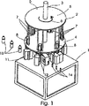
工業使用のための被覆装置6個を有する円形ロータ機械を図1に示す。概略的に示されたフレームテーブル1の上に、駆動軸3を囲み円形基板4と同心のカバー板5を持つ回転コンベア2が支えられている。駆動軸3のフレームテーブル1に対する下向きの視線方向では、回転コンベア2は作業中、湾曲矢印6に相当する反時計回りの方向(回転方向)に定常角速度で駆動可能である。
A circular rotor machine with six coating devices for industrial use is shown in FIG. On the frame table 1 schematically shown, a rotary conveyor 2 is supported which surrounds the
下方基板4は、その周辺に配された垂直支持バー7の対を載置し、一方、各対をなす支持バー7の2本のバーの間には、一様に参照番号9で識別する各被覆器具の延伸ラム(後述)用の各シリンダ8が取り付けられている。回転コンベア2は、6個の被覆装置9を載置しており、そのため図には基板4をカバー板5に接続する6対の垂直支持バー7が示されている。その下に配置される延伸ブロー金型11を有するディストリビュータブロック10は、6個の被覆装置9に対応して、基板4の下でフレームテーブル1の上に取り付けられている。金型11は、成型される容器13の雌型12を内部に有するほぼ平行6面体の片半分2つを含む。その容器13は、図1および2に示すようにボトルの形である。延伸ブロー金型11の片半分もまた、雌型12の片半分のみを含み、2つの雌型12は、延伸ブロー金型が閉じるときに互いに向き合って、完成容器13の空間を形成する。容器は垂直に立つ形で製造され移動される。その製造に必要なプリフォーム14も、開口部を上にして垂直の向きで搬送される。同様の方法で、延伸ブロー金型11の2つの片半分の間の分離面は、下から上方へ垂直に、したがって駆動軸3と平行に伸長する。延伸ブロー金型11のこれら2つの片半分は、互いに離合できるように垂直ヒンジを用い、旋回可能にその片側で接続されている。金型が開いた状態では、作業片の挿入、取出をすることができる。
The lower substrate 4 is placed with a pair of vertical support bars 7 arranged on its periphery, while the two bars of the support bar 7 forming each pair are uniformly identified by reference numeral 9. Each
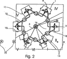
図2に基板4およびカバー板5のない平面図としても示す各被覆装置9は、延伸ブロー金型11の他にディストリビュータブロック10、圧力貯蔵装置15および流体路16を含む。
Each coating device 9, which is also shown in FIG. 2 as a plan view without the substrate 4 and the
図2はさらに、360度までの回転運動6において6個の被覆装置9の各々が一度通過する6個の角度領域を示す。これらには、プリフォーム14を導入するための角度領域Iが含まれる。反時計回り方向に、その角度領域Iにはプリフォーム14の予備ブローおよび予備形成用の大きい角度領域IIが続く。そして点火のための極めて小さい角度領域IIIが続き、その間に燃焼処理も開始されて行われる。冷却処理は、これに続き大きさがほぼ180度の角度領域IVで実行される。角度領域Vでは金型11の半分に再度開かれて、成型および被覆済みの容器13が取出される。角度領域VIは、アイドルステップの役目をしており、何らかの調整手順用の余地を提供する。
FIG. 2 further shows six angular regions through which each of the six coating devices 9 passes once in a rotational motion 6 up to 360 degrees. These include an angular region I for introducing the
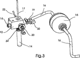
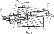
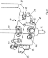
図3は、ディストリビュータブロックの10の下側に固定されたプリフォーム4を示す。延伸ラム17は、プリフォーム14と同心にディストリビュータブロック10から垂直で上向きに突出している。延伸ラム17は垂直に動くことが可能であり、予備ブロー作業において軟らかいプリフォーム14を長さ方向に延伸させるために上述のシリンダ8による直進運動で前後に動かされる。図3に示すように、延伸ラム17の垂直方向に直角に、空気接続18を通ってディストリビュータブロック10に入る空気を経由して、気体酸素が通過する。空気接続18に接続される空気路(流体路とも云う)は、図には特に示されていない。空気接続18と反対であるディストリビュータブロック10の側面では、先駆液体用弁本体19を伴った流体路16が、それに備わる計量弁に先駆物質を入れる。ディストリビュータブロック10の片側にある空気接続18を概念上の線でその反対側の弁本体19に接続すると、その線に直角でかつ延伸ラム17に直角に、水素用のさらなる流体路(図示せず)が、一様に20と識別される水素ノズルに到達し、そして図5に示す混合室21、ディストリビュータブロック10に到達する。加えて、図3は、水素ノズル20と反対であるディストリビュータブロック10の側面に、制御電圧の導入用ケーブル22とのプラグをも示す。
FIG. 3 shows a preform 4 secured to the underside of the
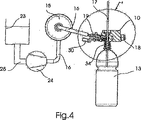
図4は、延伸ブロー金型が省略された被覆装置9の重要部分を図示し、先駆液体用の流体路16の装填を示す。先駆液体は、流体として、出力タンク23の中に大気温度と常用圧力で収容されている。図4で概略的に示されたポンプ24が、流路25を通してタンク23から先駆液体を吸い出し、40バールを超える高圧で流体路16を通って圧力貯蔵装置15に押進める。その先駆液体は、弁本体の中で、図5で概略的に示す弁26まで進められる。噴霧位置28(図5)の界面、混合室21への入口で直接噴噴霧化されるように、やはり図5に示された出口ノズル27を先駆液体が高圧で通ることができるのは、弁本体が開いているときのみである。弁26用の制御信号は、電機接続30を通って弁26に供給された流路29を通りコンピュータプログラム可能な制御(図示せず)から導入される。
FIG. 4 illustrates an important part of the coating device 9 with the stretch blow mold omitted and shows the loading of the
図5および6は、ディストリビュータブロック10の断面図を、被覆装置の特に有利な
部品と共に示す。この機械ではまた重要である垂直方向は、円筒形をした混合室50の中央に配置され、ディストリビュータブロック10中またはその混合室50を通る閉鎖部材31による密封関係で垂直の双方向矢印32の方向に上下に動くことができる延伸ラム17にある。参照番号33は、ディストリビュータブロック10から下向きに垂直に伸長する円筒部分の形をしたホルダを示し、その上には、ボトルネックから下を切取った形で示されたプリフォーム14のボトルネック34が固定されている。プリフォーム14の円筒形の内部も混合室50と直接連通していることがわかるであろう。混合室50は、閉鎖部材31のみによって上下で区切られている。図5の説明図では、視点は水素ノズル20におかれ、左側に先駆液体用出口ノズル27を見ることができる。図6では、水素供給全体を一様に35で示す。図6でそのノズル20は、排出され混合室50に流れこむ水素が螺旋状の線にそって流れはじめるように混合室50に対して接線方向に固定されている。同じことは空気接続18を通って流入する空気流についても適合する。図5では右側に端のねじ止め手段37が示されている。この端部とは空気用流体路36の装置に向かう端部である。図6に示されるように適合するように、ノズル27で噴霧化される先駆物質のために空気も接線方向で混合室50に流入する。その結果、3つの流体は、図5に示す垂直要素のある下向き方向の螺旋状の経路38を形成するので、実質的に均質な気体混合物が一方で混合室内に、他方でプリフォーム14の内部空間に導入される。図5はまたセンサ39を示す。これはディストリビュータブロック10の内部から測定ケーブル40を通って測定データを外部の評価装置(図示せず)に送る。図5に示す弁本体19は、フランジ42を伴ったアダプタ41を用いてディストリビュータブロックに保持される。
FIGS. 5 and 6 show a cross-sectional view of the
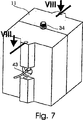
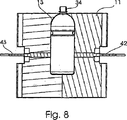
図7および8は、流体混合物の物理的特性を測定する際に関する実施例を示す。ここでは、図8に示す測定プローブ42が容器13の片側に配置されており、光源43が反対側で延伸ブロー金型11の中に配置されている。
Figures 7 and 8 show examples relating to measuring the physical properties of a fluid mixture. Here, the
被覆装置の操作に関して、準備ステップとして、連続的に調節可能な電気モータを高圧ポンプとしてのポンプ24(図4)のための駆動力として設置する。コンピュータプログラム可能制御としてPLC装置を用い、そこからの制御信号が個別の弁、センサ、レギュレータ、およびモータに行く制御ユニットに接続する。このPLCは、先駆液体用タンク23の中の液量に関する設定値、射出圧力に関する値、およびまた射出作業の開始点を制御装置に対して送る。作動手順はそれ相当に制御される方法で発生する。
With regard to the operation of the coating device, as a preparatory step, a continuously adjustable electric motor is installed as the driving force for the pump 24 (FIG. 4) as a high-pressure pump. A PLC device is used as a computer programmable control, and control signals from it connect to control units that go to individual valves, sensors, regulators, and motors. This PLC sends a set value relating to the amount of liquid in the
図2の角度領域を考慮に入れると、回転運動は、湾曲矢印6により示されるように角度領域Iの中で開始することができる。ここで延伸ブロー金型11が開き、等間隔で置かれるプリフォーム14の列の先頭プリフォームが、コンベヤ経路に沿って右から左に図2で移動の後、80〜90℃の軟化温度までの予備加熱と共に、ホルダの中にプリフォームが雌型12の中に導入される位置まで入る。そこで、プリフォームは、円筒形ホルダ33(図5)の上に、図3に示す方法で固定される。その後、延伸ブロー金型は閉じる。回転コンベヤ2は湾曲矢印6の示す方向に定常角速度で回転するので、延伸ブロー金型11が閉じられるまでの間に、装置はプリフォーム14挿入のための角度領域Iの約20度の山型領域を通過して移動している。
Taking into account the angular region of FIG. 2, the rotational movement can start in the angular region I as indicated by the curved arrow 6. Here, the
ここで閉鎖した延伸ブロー金型11は、混合室50内およびプリフォーム14の内部への気体の予備吹き込みが開始される角度領域IIに到達する。15バール以下の圧力下の室温で、空気が空気接続18を通って混合室50に吹き込まれる。次いで水素も水素供給路35を経て、混合室50に含有された酸素を含む空気と水素が流体の螺旋状経路38に対応する螺旋状の線で混合されるように、垂直方向の中心線および延伸ラム17に対し偏心している水素ノズル20を通り、混合室50内に接線方向で吹き込まれる。こうして、延伸ラム17の垂直下方運動とともに、プリフォーム14を膨張させ、究極的に所望する容器13の形状に幾分近づけるために約12〜13バールの圧力が混合室50の中に集められる。
The stretch blow
ここで先駆液体もまた、弁26(図5)が開いたことにより先駆液体用出口ノズル27およびそこの噴霧位置28に入る。約0.5〜1.5リットルの空気を、マイクロリットルの先駆液体のために使用する。その比率の結果として先駆液体の噴霧化と混合が空気と水素がすでに供給された後で開始される。それらの供給時間はやや長く、先駆物質の供給時間は制限されて短い。特に噴霧化位置28において、ポンプ24により生じた圧力とノズル27の幾何学的形状により、霧の生成または気体類似作用を持つ極微細粒子への先駆液体の転換を提供する。例えば延伸ラム17に対し15度など、接線方向に偏心した円筒形混合室50への導入に際し、先駆物質の霧は流体の螺旋状経路38に入ることができ、そこで他の気体とよく混合することができる。混合室50およびプリフォーム14の内部は、激しく渦巻く部屋のように作動する。爆発性の気体混合物(空気、酸素、水素、先駆物質)を用いる容器の最終構成の90%までの予備膨張が、約60度〜80度の角度にわたる角度領域IIを通過した後に終了する。
Here, the precursor liquid also enters the precursor liquid outlet nozzle 27 and its
角度領域IIIを通過する間に、燃焼開始用点火装置を用いて点火を実行する。点火装置は、ディストリビュータブロック10の中または延伸ラム17の中などツールの中に配置される。この角度領域IIIでは最終形成が実行され、プリフォーム14の壁は延伸ブロー金型11の雌型12の内壁に押し付けられる。点火後かつ5度〜25度、好適には15度にわたる角度領域IIIを通過の後、被覆装置は角度領域IVに入る。ここでは、冷却処理が開始され、約180度の角度領域を通過の後に終了する。容器の壁と同時に、内部被覆もまた冷却される。
While passing through the angle region III, ignition is performed using the ignition device for starting combustion. The igniter is placed in a tool such as in the
延伸ブロー金型11がまだ閉じている間に容器は角度領域Vに入る。ここでは、延伸ブロー金型11が開き、容器13を取出せる。次いで容器13は、図2の左下にある直線コンベヤ上に置かれ、左に向かって水平に外部へと移動される。その後、開いている延伸ブロー金型11は、空運転モード角度領域VIを通り、プリフォーム14挿入のための角度領域Iに入って再度プリフォームを受け取ることができる。回転コンベア上の循環がここで新たに開始される。
The container enters the angle region V while the
弁26の開口部による先駆液体の噴射は、弁26が再度閉じるまでに制御されて実行されることは理解されるだろう。ツール、すなわち金型11の上には、センサ42が測定プローブとして、図7の図に相当して配置されている。このセンサは製造過程中、容器13の外側に配置される。光源43が容器13と反対側に、図7に示す光軸上に配置されている。この方法では、容器13の中の例えば流体混合物の色特性を燃焼中または燃焼直後にも測定することが可能である。測定信号は、制御に供給され、次に続く容器の成型および被覆に直ちに影響を与えることができる。1つのセンサ(または複数のセンサ)がディストリビュータブロック10自体に配置されていれば、別の測定処理を採用することも可能である。明らかに、この方法で放射線測定をおこなうことはできないが、この場合は測定計器の設計構成は技術的に簡単である。温度、圧力、音響などに関する測定値から、連続運転工程において次に続く容器の成型および被覆に、完成製品が所望の品質を享受するような方法で影響を与えるために有用なパラメータを入手することもまた可能である。
It will be understood that the injection of the precursor liquid through the opening of the
図1および2に示す実施例においては、6個のステーションが基板4の周辺全体に配置されている。各々に含まれる技術的作業によって、1〜40のステーションを設けることも可能であることは理解されるだろう。 In the embodiment shown in FIGS. 1 and 2, six stations are arranged around the entire periphery of the substrate 4. It will be appreciated that 1 to 40 stations may be provided depending on the technical work involved.
図9〜14は、被覆装置無しで延伸ブローを用いてプラスチック容器を製造するための装置に関する本発明の実施例を示す。これらの図においては、可能な限り、同一または少なくとも同様の構成部品に関しては、用語および参照番号を再使用する。 9-14 show an embodiment of the present invention relating to an apparatus for producing plastic containers using stretch blow without a coating apparatus. In these figures, terminology and reference numbers will be reused wherever possible for identical or at least similar components.
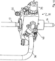
図10は、プリフォーム14に直接接続される本発明のディストリビュータヘッド10を示す。これは、図13の線B−Bに沿った断面図を示す図14で格別明瞭に見られるだろう。
FIG. 10 shows the
ディストリビュータブロック10の密封要素49少なくとも1つに対して直接押し付けられるプリフォーム14を見ることが可能である。プリフォーム14の中に伸長する延伸バーまたは延伸ラム17を見ることもまた可能である。この構成において、プリフォーム14の内部空間と共に、混合室50は燃焼室21を形成する。燃焼室21の容積が、延伸ラム17を囲む容積となって、実質的にプリフォーム14の内容積のみにより形成されているのを明確に理解できる。ディストリビュータブロック10の中にある燃焼室21の容積比は、極めて小さく、ここでは約11cm3である。図14では、ディストリビュータブロック10を通って環状混合室50の中に伸長する点火プラグ48を見ることも可能である。この代わりに、点火装置を延伸ラム17に配置することもできるのは理解されるだろう。
It is possible to see the
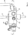
本発明によるディストリビュータブロック10のさらなる詳細は、図11の線分A−Aに沿った図12の断面図でより明らかに見ることができる。この場合も点火プラグ48が中に固定されたディストリビュータブロック10を見ることが可能である。空気供給用流体路36は、空気供給接続18に接続されている。この実施例では戻り止め弁または逆止弁の形の空気供給弁47が、環状混合空間50と関係する空気供給路を開閉する。環状混合空間50は、その中に延伸バーまたは延伸ラム17が配置されるほぼ円筒形の穴により提供される。水素用供給路35を見ることも可能であり、この供給路はニードル弁20を通って混合室50または燃焼室21に接続するができる。ニードル弁20は、この場合も逆止弁の形である。
Further details of the
燃焼室を空気出口接続44に接続する空気出口弁45も見ることが可能である。
An
ここで爆発延伸ブロー処理は次のように機能する。プリフォーム14は、先ず延伸ブロー処理に適切な温度まで加熱され、その内部形状が製造すべき容器に相当する金型(ここでは図示せず)の中に導入される。ここでプリフォームは、軸方向に動く延伸ラムにより軸方向に延伸される。同時に爆発性気体混合物が燃焼室21および混合室50の中に空気供給弁47および水素供給用の弁20を用いて生成される。この場合、気体は約3〜10バールの圧力下に置かれる。その延伸圧により、プリフォームの径も増加する。プリフォームがその軸方向長さに達すると、混合室50の中に伸長する点火プラグ48を用いて爆発性流体が点火される。この爆発により、プリフォーム内部の圧力は30〜50バールの範囲に急激に増加する。このいわゆる膨張圧力によりプリフォーム14が完全に延伸ブロー金型(図示せず)の壁に対して押圧られ、それにより製造されるボトルの形状を得る。爆発の適正な実施は、圧力センサ39を用いて監視し検出することができる。相当する圧力に達した後、空気出口弁45用の制御空気供給47を用いて空気出口弁45を開くので、圧力およびそれと共に爆発で発生する反応生成物の大部分もまた、空気出口接続44を通って外に逃げる。
Here, the explosion stretch blow processing functions as follows. The
特にディストリビュータブロック10を円形ロータ機械で使用すると、爆発の連続が非常に速いので、爆発で発生する爆発エネルギのためディストリビュータブロック10は温度上昇を受ける。
In particular, when the
したがって、ディストリビュータブロック10には閉鎖ねじ53を用いてある程度閉鎖されている冷却通路が設けられる。しかし冷却水は、冷却水入口51を通ってディストリビュータブロックの中に入り、冷却水出口52を通って再び出ることができる。このことが機械運転中に一様な処理状態が広く行き渡ることを確実にする。
Accordingly, the
1 フレームテーブル
2 回転コンベヤ
3 駆動軸
4 基板
5 カバー板
6 湾曲矢印(回転方向)
7 垂直支持バー
8 延伸ラム用シリンダ
9 被覆装置
10 ディストリビュータブロック
11 延伸ブロー金型
12 雌型
13 容器(ペットボトル)
14 プリフォーム
15 圧力貯蔵装置
16 流体路
17 延伸ラム
18 空気接続
19 先駆液体用弁本体
20 水素ノズル
21 燃焼室
22 制御電圧用ケーブル
23 先駆液体用出力タンク
24 ポンプ
25 流路
26 弁
27 先駆液体用出口ノズル
28 噴霧位置
29 制御信号用導線
30 電気接続
31 閉鎖部材
32 垂直双方向矢印
33 円筒形ホルダ
34 ボトルネック
35 流路、例えば空気用流体路
36 空気用流体路
37 スクリュー
38 流体の螺旋経路
39 センサ
40 計量ケーブル
41 アダプタ
42 測定プローブ
43 光源
44 吐出空気
45 空気出口弁
46 空気出口弁用制御
47 空気供給弁
48 点火プラグ
49 シール
50 取付けブロックの内室、混合室
51 冷却水入口
52 冷却水出口
53 閉鎖ねじ
I プリフォーム14挿入のための領域
II プリフォーム14予備膨張のための領域
III プリフォーム14点火のための領域
IV プリフォーム14冷却のための領域
V 容器13取出のための領域
VI 空運転のための領域
1 Frame table 2
7
14
Claims (11)
前記円形ロータ機械(2)は、複数のディストリビュータブロック(10)と、前記複数のディストリビュータブロック(10)及び複数のプリフォーム(14)を支持するとともに回転させる回転台を有しており、 The circular rotor machine (2) has a plurality of distributor blocks (10) and a turntable that supports and rotates the plurality of distributor blocks (10) and the plurality of preforms (14),
前記ディストリビュータブロック(10)は、混合室(50)と、前記混合室(50)に爆発性流体を形成する異なる少なくとも2つの流体を供給する少なくとも2つの別個の通路と、前記爆発性流体に点火するための点火装置とを有しており、 The distributor block (10) includes a mixing chamber (50), at least two separate passages for supplying at least two different fluids forming the explosive fluid to the mixing chamber (50), and igniting the explosive fluid. And an ignition device for
更に、前記ディストリビュータブロック(10)は、前記プリフォーム(14)又は容器に直接接続することができ、前記混合室(50)と前記プリフォーム(14)の内部空間により燃焼室(21)を形成していることを特徴とする機械。 Further, the distributor block (10) can be directly connected to the preform (14) or a container, and a combustion chamber (21) is formed by the mixing chamber (50) and the internal space of the preform (14). A machine characterized by
ロック装置を有し、前記弁は前記爆発性流体の爆発に際して発生する圧力により前記ロック装置が開放されるとき自動的に開くこと、を特徴とする請求項6に記載の装置。 A valve for opening and closing the chain of said fluid discharge passage is provided, wherein the valve has a locking device which prevents opening of the explosive fluid, the valve is the locking device by the pressure generated during detonation of the explosive fluid 7. The device of claim 6, wherein the device automatically opens when opened.
Applications Claiming Priority (3)
| Application Number | Priority Date | Filing Date | Title |
|---|---|---|---|
| DE10211878 | 2002-03-18 | ||
| DE10231345A DE10231345A1 (en) | 2002-03-18 | 2002-07-11 | Device for producing plastic containers by means of stretch blow molding and device for coating the inner walls of a plastic container |
| PCT/EP2003/002736 WO2003078136A2 (en) | 2002-03-18 | 2003-03-17 | Device for the production of plastic containers by means of stretch blow moulding and device for coating the inner walls of a plastic container |
Publications (2)
| Publication Number | Publication Date |
|---|---|
| JP2005520707A JP2005520707A (en) | 2005-07-14 |
| JP4570876B2 true JP4570876B2 (en) | 2010-10-27 |
Family
ID=28042847
Family Applications (1)
| Application Number | Title | Priority Date | Filing Date |
|---|---|---|---|
| JP2003576172A Expired - Lifetime JP4570876B2 (en) | 2002-03-18 | 2003-03-17 | Circular rotor machine for producing plastic containers using stretch blow |
Country Status (14)
| Country | Link |
|---|---|
| US (1) | US7481636B2 (en) |
| EP (1) | EP1487628B1 (en) |
| JP (1) | JP4570876B2 (en) |
| CN (1) | CN100528536C (en) |
| AT (1) | ATE340686T1 (en) |
| AU (1) | AU2003229561B2 (en) |
| BR (1) | BR0308467B1 (en) |
| CA (1) | CA2460670C (en) |
| DE (2) | DE10231345A1 (en) |
| ES (1) | ES2270018T3 (en) |
| MX (1) | MXPA04008941A (en) |
| RU (1) | RU2312016C2 (en) |
| TW (1) | TWI266685B (en) |
| WO (1) | WO2003078136A2 (en) |
Families Citing this family (26)
| Publication number | Priority date | Publication date | Assignee | Title |
|---|---|---|---|---|
| DE10354625A1 (en) * | 2003-11-22 | 2005-06-30 | Sig Technology Ltd. | Method for determining the gas permeability of container walls, containers with surface coating and coating device with measuring device |
| DE102004008400A1 (en) * | 2004-02-20 | 2005-09-08 | Sig Technology Ltd. | Device for processing workpieces |
| FR2872082B1 (en) * | 2004-06-23 | 2006-10-06 | Sidel Sas | INSTALLATION FOR BLOWING CONTAINERS IN THERMOPLASTIC MATERIAL |
| DE102004043384B4 (en) * | 2004-09-08 | 2010-06-17 | Schott Ag | Process for producing a coated hollow body substrate of at least polyethylene terephthalate |
| DE102005015063B4 (en) * | 2005-03-31 | 2008-05-15 | Schott Ag | Apparatus and method for the automatic generation of control instructions for rotary machines |
| FR2917068B1 (en) * | 2007-06-07 | 2012-10-12 | Sidel Participations | POLYMER CONTAINER HAVING A CRYSTALLINITE GRADIENT |
| FR2917004B1 (en) * | 2007-06-07 | 2012-10-26 | Sidel Participations | METHOD OF MANUFACTURING BLOWED CONTAINERS FOR IMPROVING THEIR MECHANICAL STRENGTH |
| DE102008010885A1 (en) | 2008-02-25 | 2009-08-27 | Krones Ag | Apparatus and method for monitoring the operability of a container treatment apparatus |
| DE102008013419A1 (en) | 2008-03-06 | 2009-09-10 | Khs Corpoplast Gmbh & Co. Kg | Method and apparatus for blow molding containers |
| DE102008049905A1 (en) * | 2008-10-02 | 2010-04-08 | Krones Ag | Quick change system for stretching bars |
| DE102009036922A1 (en) | 2009-08-11 | 2011-02-17 | Krones Ag | Blow molding machine with cleaning system |
| KR101390247B1 (en) * | 2009-09-18 | 2014-04-30 | 가부시키가이샤 이엠이 | Fluid filling device |
| US8485810B2 (en) * | 2010-10-06 | 2013-07-16 | Graham Engineering Corporation | Blow molding apparatus |
| DE102010042165A1 (en) * | 2010-10-07 | 2012-04-12 | Krones Aktiengesellschaft | Process for treating at least one container in a container treatment plant |
| DE102011104024A1 (en) | 2011-06-06 | 2012-12-06 | Khs Corpoplast Gmbh | Method and device for sterilizing and device for blow molding of containers |
| JP2014527484A (en) * | 2011-08-08 | 2014-10-16 | ネステク ソシエテ アノニム | Rotating system for simultaneous blow molding from preform to plastic container and filling into this container |
| JP6065266B2 (en) | 2012-11-30 | 2017-01-25 | 株式会社吉野工業所 | Synthetic resin windowed container, preform and preform injection molding device |
| FR3001913B1 (en) * | 2013-02-14 | 2015-02-27 | Sidel Participations | "INSTALLATION FOR FORMING BLOWED CONTAINERS COMPRISING AN IMPROVED DEVICE FOR CONTROLLING A BLOWING FLUID DISPENSING VALVE" |
| WO2015023673A2 (en) | 2013-08-12 | 2015-02-19 | Agr International, Inc. | Blow molder control systems snad methods |
| EP3172029B1 (en) * | 2014-07-21 | 2018-06-06 | Gea Procomac S.p.A. | Moulding device for moulding a container starting with a parison in plastic material and moulding machine comprising this device |
| DE102014010861A1 (en) * | 2014-07-25 | 2016-01-28 | Khs Corpoplast Gmbh | Volume controlled blast air supply |
| CA3210826A1 (en) * | 2015-01-13 | 2016-07-13 | Stackteck Systems Limited | Post-mold cooling method and apparatus with cyclone cooling effect |
| WO2016143772A1 (en) * | 2015-03-09 | 2016-09-15 | 大日本印刷株式会社 | Blow molding machine and sterilization method therefor |
| US20190240889A1 (en) * | 2016-10-18 | 2019-08-08 | Reifenhaeuser Gmbh & Co. Kg Maschinenfabrik | Method and data detection device for providing, retrieving and using a data element in a process for producing plastic sheet material |
| WO2019152365A1 (en) | 2018-02-01 | 2019-08-08 | Agr International, Inc. | Energy effecient blow molder control |
| CN113993682B (en) | 2019-04-09 | 2024-07-19 | 日精Asb机械株式会社 | Apparatus for manufacturing resin container |
Family Cites Families (22)
| Publication number | Priority date | Publication date | Assignee | Title |
|---|---|---|---|---|
| US2892733A (en) * | 1955-09-16 | 1959-06-30 | Plax Corp | Method and apparatus for treating synthetic resin containers |
| US3100910A (en) * | 1958-04-10 | 1963-08-20 | Cons Thermoplastics Company | Apparatus for the explosion treatment of a plastic container |
| US3236080A (en) * | 1961-07-10 | 1966-02-22 | Continental Can Co | Procedure and device for the shaping of containers, container bodies or container parts, from a thin-walled first shape |
| US3252312A (en) | 1962-04-25 | 1966-05-24 | Continental Can Co | Method and apparatus for explosive reshaping of hollow ductile objects |
| US3694424A (en) * | 1970-10-13 | 1972-09-26 | Hunkar Laboratories | Method of internally cooling a blow molded article |
| DE2742693C2 (en) | 1977-09-22 | 1983-08-11 | Gildemeister Corpoplast Gmbh, 2000 Hamburg | Machine for blow molding hollow bodies, in particular bottles, made of thermoplastic material |
| JPS5627330A (en) | 1979-08-15 | 1981-03-17 | Yoshino Kogyosho Co Ltd | Heat treatment for internal wall surface of saturated polyester resin biaxially stretched bottle |
| JPS5627329A (en) | 1979-08-15 | 1981-03-17 | Yoshino Kogyosho Co Ltd | Reducing method for residual strain of biaxially stretched saturated polyester resin bottle |
| DE3312920C1 (en) | 1983-04-11 | 1984-10-11 | ESG Elektronik-System-GmbH, 8000 München | Method for producing a hollow body |
| FR2700293B1 (en) * | 1993-01-08 | 1995-03-24 | Settembrini Antoine Di | Blow molding machine. |
| CH687601A5 (en) | 1994-02-04 | 1997-01-15 | Tetra Pak Suisse Sa | Process for the production of internally sterile packaging with excellent barrier properties. |
| US5565248A (en) | 1994-02-09 | 1996-10-15 | The Coca-Cola Company | Method and apparatus for coating hollow containers through plasma-assisted deposition of an inorganic substance |
| CH691218A5 (en) | 1996-08-14 | 2001-05-31 | Tetra Laval Holdings & Finance | Process for the sterilization of surfaces of any object. |
| NL1003827C2 (en) * | 1996-08-19 | 1998-02-26 | Thomassen & Drijver | Device for remodeling a hollow metal object. |
| PL339616A1 (en) | 1997-09-30 | 2001-01-02 | Tetra Laval Holdings & Finance | Method of and apparatus for treating internal surface of a plastic bottle in a plasma-assisted process |
| DE19938724A1 (en) * | 1999-08-16 | 2001-02-22 | Tetra Laval Holdings & Finance | Device for the production of plastic containers by means of stretch blow molding |
| DE10004274A1 (en) | 2000-02-01 | 2001-08-02 | Tetra Laval Holdings & Finance | Device for coating the inner surface of a hollow body |
| DE10011276A1 (en) * | 2000-03-08 | 2001-09-13 | Wolff Walsrode Ag | Process employing indirect atmospheric plasmatron, surface-treats or coats thin metallic foil or polymer sheet |
| FR2812568B1 (en) | 2000-08-01 | 2003-08-08 | Sidel Sa | BARRIER COATING DEPOSITED BY PLASMA COMPRISING AN INTERFACE LAYER, METHOD FOR OBTAINING SUCH A COATING AND CONTAINER COATED WITH SUCH A COATING |
| DE10065652B4 (en) * | 2000-12-29 | 2007-09-27 | Tetra Laval Holdings & Finance S.A. | Device for the production of plastic containers by stretch blow molding |
| DE10114401B4 (en) * | 2001-03-23 | 2005-03-17 | Tetra Laval Holdings & Finance S.A. | Method for blow molding a container made of plastic and for coating the container interior |
| DE10118242A1 (en) | 2001-06-09 | 2002-12-12 | Andreas Biedermann | Protective coating, for the inner surface of a hollow container, is through detonation of a gas which contains precursors for the coating material |
-
2002
- 2002-07-11 DE DE10231345A patent/DE10231345A1/en not_active Ceased
-
2003
- 2003-03-17 EP EP03722343A patent/EP1487628B1/en not_active Expired - Lifetime
- 2003-03-17 US US10/507,569 patent/US7481636B2/en not_active Expired - Lifetime
- 2003-03-17 RU RU2004130851/12A patent/RU2312016C2/en active
- 2003-03-17 DE DE50305181T patent/DE50305181D1/en not_active Expired - Lifetime
- 2003-03-17 AU AU2003229561A patent/AU2003229561B2/en not_active Expired
- 2003-03-17 WO PCT/EP2003/002736 patent/WO2003078136A2/en not_active Ceased
- 2003-03-17 AT AT03722343T patent/ATE340686T1/en active
- 2003-03-17 CA CA2460670A patent/CA2460670C/en not_active Expired - Lifetime
- 2003-03-17 JP JP2003576172A patent/JP4570876B2/en not_active Expired - Lifetime
- 2003-03-17 TW TW092105800A patent/TWI266685B/en not_active IP Right Cessation
- 2003-03-17 MX MXPA04008941A patent/MXPA04008941A/en active IP Right Grant
- 2003-03-17 CN CNB038015846A patent/CN100528536C/en not_active Expired - Lifetime
- 2003-03-17 ES ES03722343T patent/ES2270018T3/en not_active Expired - Lifetime
- 2003-03-17 BR BRPI0308467-1A patent/BR0308467B1/en active IP Right Grant
Also Published As
| Publication number | Publication date |
|---|---|
| BR0308467B1 (en) | 2012-12-11 |
| TWI266685B (en) | 2006-11-21 |
| RU2004130851A (en) | 2006-01-27 |
| US20060110483A1 (en) | 2006-05-25 |
| US7481636B2 (en) | 2009-01-27 |
| CA2460670C (en) | 2010-08-17 |
| RU2312016C2 (en) | 2007-12-10 |
| MXPA04008941A (en) | 2004-11-26 |
| WO2003078136A2 (en) | 2003-09-25 |
| EP1487628A2 (en) | 2004-12-22 |
| CA2460670A1 (en) | 2003-09-25 |
| EP1487628B1 (en) | 2006-09-27 |
| ES2270018T3 (en) | 2007-04-01 |
| WO2003078136A3 (en) | 2003-12-11 |
| BR0308467A (en) | 2005-01-11 |
| AU2003229561B2 (en) | 2008-03-06 |
| AU2003229561A1 (en) | 2003-09-29 |
| DE10231345A1 (en) | 2003-10-16 |
| CN1602247A (en) | 2005-03-30 |
| JP2005520707A (en) | 2005-07-14 |
| TW200304869A (en) | 2003-10-16 |
| ATE340686T1 (en) | 2006-10-15 |
| DE50305181D1 (en) | 2006-11-09 |
| CN100528536C (en) | 2009-08-19 |
Similar Documents
| Publication | Publication Date | Title |
|---|---|---|
| JP4570876B2 (en) | Circular rotor machine for producing plastic containers using stretch blow | |
| CA2381273C (en) | Device for manufacturing plastics containers by means of stretch blow forming | |
| CN100333892C (en) | Method for blosing forming container made of plastic and for coating the inside of said container | |
| AU2003245890A1 (en) | Multistation coating device and method for plasma coating | |
| WO2004012999A2 (en) | Ultraviolet bottle coating thickness measurement | |
| US6315939B1 (en) | Process for producing stretch blow formed plastic containers | |
| EP0129445A1 (en) | Process for forming tamper-resistant tamper-indicative capsules | |
| GB2149377A (en) | Forming tamper-resistant tamper-indicative capsules | |
| US4466844A (en) | Gripper for capsule welder | |
| CN1516643A (en) | Method and apparatus for treating plastic substrate parts to accept paint with redundancy without adhesion promoters | |
| JP2004292223A (en) | Powder production apparatus | |
| CN208328051U (en) | A kind of production line removed from office for processing automobile | |
| US20040232582A1 (en) | Method and apparatus with redundancies, for treating substrate plastic parts to accept paint without using adhesion promoters | |
| JP4067404B2 (en) | Plastic container manufacturing equipment by stretch blow molding | |
| JP4100084B2 (en) | Container molding method | |
| CN100515730C (en) | Air splitter for plastic stretch blow molding machine | |
| CN119348111A (en) | Container preparation system and preparation method for coupled blow molding and plasma coating | |
| CN120645548A (en) | Beverage cup automatic printing, packaging and marking device | |
| CN101293186A (en) | Micro-nano powder mixing and surface modification equipment | |
| JPS646840A (en) | Powder friction testing device | |
| TH25387A (en) | Finishing machines and methods for producing plastic containers coated with carbon film. | |
| JPH06293055A (en) | Method and device for blow molding hollow body out of thermoplastic material | |
| MXPA03009504A (en) | Method and apparatus, with redundancies, for treating substrate plastic parts to accept paint without using adhesion promoters. |
Legal Events
| Date | Code | Title | Description |
|---|---|---|---|
| A621 | Written request for application examination |
Free format text: JAPANESE INTERMEDIATE CODE: A621 Effective date: 20060207 |
|
| A131 | Notification of reasons for refusal |
Free format text: JAPANESE INTERMEDIATE CODE: A131 Effective date: 20080624 |
|
| A601 | Written request for extension of time |
Free format text: JAPANESE INTERMEDIATE CODE: A601 Effective date: 20080924 |
|
| A602 | Written permission of extension of time |
Free format text: JAPANESE INTERMEDIATE CODE: A602 Effective date: 20081008 |
|
| A521 | Request for written amendment filed |
Free format text: JAPANESE INTERMEDIATE CODE: A523 Effective date: 20081224 |
|
| A131 | Notification of reasons for refusal |
Free format text: JAPANESE INTERMEDIATE CODE: A131 Effective date: 20090217 |
|
| A601 | Written request for extension of time |
Free format text: JAPANESE INTERMEDIATE CODE: A601 Effective date: 20090515 |
|
| A602 | Written permission of extension of time |
Free format text: JAPANESE INTERMEDIATE CODE: A602 Effective date: 20090525 |
|
| A521 | Request for written amendment filed |
Free format text: JAPANESE INTERMEDIATE CODE: A523 Effective date: 20090605 |
|
| TRDD | Decision of grant or rejection written | ||
| A01 | Written decision to grant a patent or to grant a registration (utility model) |
Free format text: JAPANESE INTERMEDIATE CODE: A01 Effective date: 20100720 |
|
| A01 | Written decision to grant a patent or to grant a registration (utility model) |
Free format text: JAPANESE INTERMEDIATE CODE: A01 |
|
| A61 | First payment of annual fees (during grant procedure) |
Free format text: JAPANESE INTERMEDIATE CODE: A61 Effective date: 20100811 |
|
| FPAY | Renewal fee payment (event date is renewal date of database) |
Free format text: PAYMENT UNTIL: 20130820 Year of fee payment: 3 |
|
| R150 | Certificate of patent or registration of utility model |
Ref document number: 4570876 Country of ref document: JP Free format text: JAPANESE INTERMEDIATE CODE: R150 Free format text: JAPANESE INTERMEDIATE CODE: R150 |
|
| R250 | Receipt of annual fees |
Free format text: JAPANESE INTERMEDIATE CODE: R250 |
|
| R250 | Receipt of annual fees |
Free format text: JAPANESE INTERMEDIATE CODE: R250 |
|
| R250 | Receipt of annual fees |
Free format text: JAPANESE INTERMEDIATE CODE: R250 |
|
| R250 | Receipt of annual fees |
Free format text: JAPANESE INTERMEDIATE CODE: R250 |
|
| R250 | Receipt of annual fees |
Free format text: JAPANESE INTERMEDIATE CODE: R250 |
|
| R250 | Receipt of annual fees |
Free format text: JAPANESE INTERMEDIATE CODE: R250 |
|
| R250 | Receipt of annual fees |
Free format text: JAPANESE INTERMEDIATE CODE: R250 |
|
| R250 | Receipt of annual fees |
Free format text: JAPANESE INTERMEDIATE CODE: R250 |
|
| R250 | Receipt of annual fees |
Free format text: JAPANESE INTERMEDIATE CODE: R250 |
|
| R250 | Receipt of annual fees |
Free format text: JAPANESE INTERMEDIATE CODE: R250 |
|
| EXPY | Cancellation because of completion of term |