JP4568263B2 - A prop of protective body such as avalanche and falling rock - Google Patents
A prop of protective body such as avalanche and falling rock Download PDFInfo
- Publication number
- JP4568263B2 JP4568263B2 JP2006271267A JP2006271267A JP4568263B2 JP 4568263 B2 JP4568263 B2 JP 4568263B2 JP 2006271267 A JP2006271267 A JP 2006271267A JP 2006271267 A JP2006271267 A JP 2006271267A JP 4568263 B2 JP4568263 B2 JP 4568263B2
- Authority
- JP
- Japan
- Prior art keywords
- column
- support
- distal end
- receiving
- receiving portion
- Prior art date
- Legal status (The legal status is an assumption and is not a legal conclusion. Google has not performed a legal analysis and makes no representation as to the accuracy of the status listed.)
- Active
Links
Images


Description
本発明は、防護柵等の雪崩・落石等防護体の支柱に関する。 The present invention relates to a support column for a protection body such as an avalanche or falling rock such as a protection fence.
従来から山腹の斜面部等に構築して落石や積雪等を受け止めて道路等への落下、流入を防止する防護柵が知られており、例えば、山腹の斜面部に間隔を置いて縦孔を穿孔し、この縦孔に建て込んだパイプ支柱を並設すると共に、これら各パイプ支柱に複数段のケーブルとともに金網を張設した落石等の防護柵(例えば特許文献1)が提案されている。 Conventionally, protective fences have been known that are constructed on slopes of mountainsides to prevent falling or inflowing on roads etc. by receiving falling rocks and snow, etc.For example, vertical holes are provided at intervals on slopes of mountainsides. There has been proposed a protective fence such as a rock fall (for example, Patent Document 1) in which pipe struts that are drilled and built in the vertical holes are arranged side by side, and a wire mesh is stretched along with a plurality of cables on each of the pipe struts.
また、設定面に間隔をおいて穿孔した複数の縦孔に支柱を建て込み、これら支柱の間に上下に間隔を置いて架設する複数の索条体と共に防護用網体を張設した防護柵(例えば特許文献2)や、セメントを混合した混合材である無収縮モルタルを充填した落石・雪崩等保護構造物用充填鋼管を用い、この充填鋼管を基礎に固定する(例えば特許文献3)ものが知られている。 In addition, a protective fence in which a support net is installed in a plurality of vertical holes drilled at intervals on the setting surface, and a protection net is stretched together with a plurality of cable bodies that are installed with a vertical space between the support columns. (For example, Patent Document 2), or a filled steel pipe for protection structures such as rock fall and avalanche filled with non-shrink mortar which is a mixed material mixed with cement, and this filled steel pipe is fixed to the foundation (for example, Patent Document 3) It has been known.
また、落石などの衝撃を摩擦エネルギーに変換して吸収するものとして、所定の間隔で支柱を設け、各支柱の間に水平ロープ材を水平方向のスライドを許容した状態で係留し、水平ロープ材の両端は固定し、各支柱間を水平ロープ材に掛止させたワイヤ製のネットで遮蔽し、前記水平ロープ材の途上にロープ材を重合させて形成した余長部と、余長部を一定の力で挟持する挟持具とにより、水平ロープ材に設定張力以上の張力が作用したとき、水平ロープ材が一定の摩擦力を保持したまま余長部が伸長して張力を吸収する緩衝部を形成した衝撃吸収柵(例えば特許文献4、特許文献5)が提案されている。 In addition, as a means to absorb impacts such as falling rocks by converting them into frictional energy, support columns are provided at predetermined intervals, and horizontal rope materials are moored in a state that allows horizontal sliding between each support column. Both ends of the cable are fixed, shielded between wires by a wire net hooked on a horizontal rope material, and an extra length portion formed by polymerizing the rope material in the middle of the horizontal rope material, and an extra length portion. A buffer that absorbs tension by extending the extra length of the horizontal rope material while maintaining a constant frictional force when a tension higher than the set tension is applied to the horizontal rope material due to the clamping device that clamps with a constant force A shock absorbing fence (for example, Patent Document 4 and Patent Document 5) in which a slab is formed has been proposed.
また、衝撃吸収杭において、埋設用の筒状体と、上部が地上に突出するように該筒状体に内挿される杭本体と、該筒状体と該杭本体との間に充填される充填材とを備えたもの(例えば特許文献6)がある。
上記特許文献3の防護柵では、斜面に構築した防護柵によって積雪や雪崩等を効果的に受け止めることで、落石や雪崩といった自然災害を抑制することができ、また、特許文献4及び5の衝撃吸収柵では、衝撃を支柱に伝える前に水平ロープ材の一部に形成した緩衝部の摺動により衝撃を吸収することができ、従来に比較して支柱の荷重負荷を軽減できる。
In the protective fence of
ところで、緩衝部を設けても、この種の防護柵において、支柱の強度が荷重に対する性能に大きく寄与し、支柱の強度を向上するには、支柱自体とともに取付強度を向上する必要がある。このため、基礎に形成した縦孔に支柱の下部を建て込み、所定の取付強度を得るようにしている。 By the way, even if it provides a buffer part, in this kind of guard fence, in order to improve the strength of a support | pillar, the intensity | strength of a support | pillar greatly needs to improve attachment strength with support | pillar itself. For this reason, the lower part of a support | pillar is built in the vertical hole formed in the foundation, and predetermined attachment strength is obtained.
そして、防護柵の設定条件により、支柱が長尺となる場合があり、例えば、雪崩予防柵などでは、積雪に応じた上部柵高さとこれに対応した下部部分が必要となり、支柱が長尺となる。一方、鋼管などを支柱の材料に用いる場合、防錆などの面からメッキ処理が施される。 And depending on the setting conditions of the protective fence, the pillar may be long.For example, in an avalanche prevention fence, the upper fence height corresponding to snow accumulation and the lower part corresponding to this are required, and the pillar is long. Become. On the other hand, when a steel pipe or the like is used as the material for the support, plating is performed from the aspect of rust prevention or the like.
そのようなメッキ処理は、メッキ槽に支柱を漬ける所謂どぶ漬けが行われるが、長尺な支柱を処理できるメッキ層が少なく、支柱が長くなると、製作工程と製作コストの面で不利になる。しかし、上記特許文献のものは、いずれも支柱又は杭に一体物を用いており、このような問題が予想される。 In such plating treatment, so-called soaking is performed in which a support is immersed in a plating tank, but there are few plating layers capable of processing a long support, and if the support becomes longer, it is disadvantageous in terms of manufacturing process and manufacturing cost. However, all of the above-mentioned patent documents use an integrated object for a support or a pile, and such a problem is expected.
加えて、メッキ槽内の高温のメッキ液に支柱を漬けるため、熱影響により支柱に歪みが発生すると、製品誤差が大きくなる。さらに、長尺な支柱は、車載寸法に制限を受け易いと共に、現場搬入時にも制約を受け易く、施工性の低下を招き易い。 In addition, since the support is immersed in the high-temperature plating solution in the plating tank, if the support is distorted due to thermal effects, the product error increases. In addition, the long support column is easily limited by the in-vehicle dimensions, and is also easily restricted at the time of carrying in the field, so that the workability is likely to be deteriorated.
一方、製造面から見ると、支柱の使用される条件や場所などによって支柱の長さが異なる場合が多く、支柱上部は標準寸法に設定できても、地山に建て込む支柱下部の長さを、現場に合わせて変えるため、標準寸法で対応することができず、その都度、異なる長さの支柱を製造する必要がある。 On the other hand, when viewed from the manufacturing side, the length of the column often varies depending on the conditions and place where the column is used. In order to change according to the site, it is not possible to cope with standard dimensions, and it is necessary to manufacture struts of different lengths each time.
このため、支柱は、多品種少量生産となり、また、予め標準品を製造しておくことができないため、納期遅れやコストアップを招く問題がある。 For this reason, there is a problem in that the support column is produced in a large variety and in small quantities, and a standard product cannot be manufactured in advance, resulting in a delay in delivery and an increase in cost.
ところで、特許文献6では、筒状体に杭本体を内挿する技術が開示されているが、このように杭本体より大径な筒状体を用いると、この筒状体に合わせて掘削孔を大きくしなければならず、通常の杭本体を用いる場合より、工数および工事費が上昇する問題がある。
By the way, in
そこで、本発明は、支柱の運搬及び搬入が容易で、且つ掘削を伴い現場での作業性を向上することができる雪崩・落石等防護体の支柱を提供することを目的とする。 Therefore, an object of the present invention is to provide a support column for a protection body such as an avalanche and rock fall that can easily carry and carry in the support column and can improve workability on site with excavation.
請求項1の発明は、基礎に固定する断面円形の支柱下部と、この支柱下部の上部に設ける断面円形の支柱上部とを連結した支柱において、前記支柱上部と支柱下部の一方の端部に前記支柱の外径より小さい挿入部を設け、この挿入部を挿入する受部を前記支柱上部と支柱下部の他方の端部に設け、前記挿入部の外周に円周方向等間隔で複数箇所設けられた該挿入部長さ方向のガイド溝と、このガイド溝に挿入され、前記受部の内面に設けられた該受部長さ方向のガイド突条とを備え、前記ガイド突条は、前記受部の端部から内部側に向って高くなる傾斜縁部を有するものである。 According to a first aspect of the present invention, there is provided a strut in which a lower section of a column having a circular cross section fixed to a foundation and an upper section of a column having a circular section provided at an upper portion of the lower section of the column are connected. the outer diameter smaller than the insertion portion of the strut is provided, the receiving portion for inserting the insertion portion provided at the other end of the strut top and post bottom, a plurality of locations set in the circumferential direction at equal intervals on the outer circumference of the insertion portion and the insert length direction of the guide groove which is being inserted into the guide groove, and a receiving portion of the longitudinal guide projection provided on the inner surface of the receiving portion, the guide protrusion, the receiving part It has an inclined edge part which becomes higher from the end part toward the inside .
また、請求項2の発明は、前記挿入部は、先端に該挿入部の外径より外形寸法が小さい先端部を備え、この先端部を挿入する先端受部を前記受部に設けたものである。 According to a second aspect of the present invention, the insertion portion includes a distal end portion whose outer dimension is smaller than the outer diameter of the insertion portion at the distal end, and a distal end receiving portion into which the distal end portion is inserted is provided in the receiving portion. is there.
また、請求項3の発明は、前記先端部と前記先端受部の断面形状が多角形をなすものである。
The invention of
また、請求項4の発明は、前記受部に挿入した前記挿入部と前記受部との間に充填した接合剤により、前記支柱上部と前記支柱下部を接合したものである。 According to a fourth aspect of the present invention, the upper portion of the support column and the lower portion of the support column are joined by a bonding agent filled between the insertion portion inserted into the receiving portion and the receiving portion.
請求項1の構成によれば、挿入部に受部を挿入固定することにより、支柱上部と支柱下部とを一体化することができ、その支柱下部を設置場所に固定することにより、防護体の支柱を立設することができる。また、挿入部が支柱より小さく形成されているため、受部も小さく済み、支柱下部と支柱上部の連結部分で支柱が太くなることがなく、したがって、支柱を挿入する掘削孔が大径になることがない。
According to the configuration of
このようにして、長尺な支柱を、支柱下部と支柱上部に分けて運搬、搬入することができ、現場での据付作業性を向上することができる。また、支柱をメッキ処理する場合では、一体物より支柱上部及び支柱下部は短くなるため、そのメッキ処理を容易に行うことができる。さらに、支柱上部と支柱下部とに分割することにより、支柱上部を標準化して予め製造しておくことができる。 In this way, a long column can be transported and carried in divided into a column lower part and a column upper part, and installation workability at the site can be improved. Further, in the case where the support is plated, the upper part of the support and the lower part of the support are shorter than the single body, so that the plating process can be easily performed. Furthermore, the upper part of a support | pillar can be standardized and manufactured beforehand by dividing | segmenting into a support | pillar upper part and a support | pillar lower part.
また、請求項2の構成によれば、挿入部が受部に挿入されると共に、挿入部の先端部が先端受部に挿入され、このような二重挿入構造により、良好な連結強度が得られる。
According to the configuration of
また、請求項3の構成によれば、多角形に多角形を挿入し、これら多角形の一辺を、支柱が荷重を受けた際の引張領域側に配置することにより、支柱の連結箇所近傍の強度を確保することができる。
Moreover, according to the structure of
また、請求項4の構成によれば、接合剤により、受部に挿入部を所定強度で接合することができる。 Moreover, according to the structure of Claim 4, an insertion part can be joined to a receiving part with predetermined intensity | strength with a joining agent.
また、請求項1の構成によれば、長さ方向のガイド突条をガイド溝に挿入することにより、受部内に挿入部をスムーズに挿入することができる。
Moreover, according to the structure of
本発明における好適な実施の形態について、添付図面を参照しながら詳細に説明する。なお、以下に説明する実施の形態は、特許請求の範囲に記載された本発明の内容を限定するものではない。また、以下に説明される構成の全てが、本発明の必須要件であるとは限らない。各実施例では、従来とは異なる雪崩・落石等防護体の支柱を採用することにより、従来にない雪崩・落石等防護体の支柱が得られ、その雪崩・落石等防護体の支柱を夫々記述する。 Preferred embodiments of the present invention will be described in detail with reference to the accompanying drawings. The embodiments described below do not limit the contents of the present invention described in the claims. In addition, all of the configurations described below are not necessarily essential requirements of the present invention. In each of the examples, by using a different avalanche / falling rock protector support column, conventional avalanche / fall rock protector support columns were obtained, and the avalanche / fall rock protector column was described respectively. To do.
以下、本発明の防護柵の実施例1について図1〜図18を参照して説明する。落石・雪崩等防護柵1は、複数の支柱2,2…を間隔をおいて並設し、それら支柱2,2…間に横ロープ材3,3…を多段に設けると共に、それら支柱2,2…間を、防護面たる網体4により閉塞してなる。
Hereinafter,
また、図中5は、支柱2の上部と、防護壁1の前側の斜面Yとを連結する控えロープ材であり、この控えロープ材5の一端を前記支柱2の上部に連結し、控えロープ5の他端を前記斜面Yにアンカー6により固定している。
次に、前記支柱2の詳細について説明すると、その支柱2は、支柱上部2Uと支柱下部2Sとを連結してなり、それら支柱下部2Sと支柱上部2Uには、一例として、充填鋼.管11が用いられる。
Next, the details of the
図2〜図4に示すように、充填鋼管11は、断面円形の鋼管12内に、断面略三角形状の補強体13を挿入配置して該鋼管12に固定した後、内部に無収縮モルタルなどの充填材14を充填し、養生したものである。前記補強体13は、板材からなる3枚の補強リブ15,15,15をほぼ正三角形に配置し、補強リブ15,15,15の頂部15S,15S,15Sに帯状鋼板16,16,16を溶着してなる。また、前記帯状鋼板16の幅Wは、前記補強リブ15の厚さTの2倍以上である。また、補強体13の帯状鋼板16,16,16は、前記鋼管2の内面と僅かな隙間を介して挿通可能に取付けられている。
As shown in FIGS. 2 to 4, the filled
そして、製造時には、補強体13を組立てた後、鋼管12の一側開口から該補強体13を挿入配置し、溶接棒などが届く開口側で補強体13を鋼管12の内面に溶着固定した後、内部に無収縮充填材14を充填する。また、図4に示すように、補強リブ15の端部は溶接部17により帯状鋼板12に固定される。
And at the time of manufacturing, after assembling the reinforcing
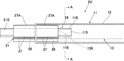
図5及び図8などに示すように、支柱上部2Uの下部には、挿入部21が設けられ、この挿入部21は、長さ方向略中央で対象形状の挿入体22の先端側により構成される。この挿入体22は、前記鋼管12内に基端側を挿入して固定する接続管23を備え、この接続管23は比較的肉厚な鋼管などからなり、その接続管23内に接続補強体24が挿入固定され、この接続補強体24の基端側及び先端側は接続管23の基端及び先端から所定寸法だけ突出し、前記接続用補強体24の先端から突出した先端が、挿入部23の外径より外形寸法が小さい先端部21Sを構成する。また、その接続管23の長さ方向中央には、鍔部25が周設され、この鍔部25は前記支柱上部2Uの鋼管12の下端に当接した状態で固定される。
As shown in FIG. 5 and FIG. 8 and the like, an
図7などに示すように、前記接続補強体24は、前記補強体13より小型の略相似形で略同一構成をなすものであり、その接続補強体24は、板材からなる3枚の補強リブ115,115,115をほぼ正三角形に配置して略三角形状をなし、補強リブ115,115,115の頂部115S,115S,115Sに帯状鋼板116,116,116を溶着してなり、前記補強体13内に挿入可能な大きさを有する。また、前記補強体13の下端13Kは、前記接続管23を鋼管12に挿入する部分に対応して、該鋼管12の下端から離れた位置にある。尚、図示しないが、充填材14は、接続管23の先端まで充填されているが、さらに、接続補強体24の先端まで充填してもよい。
As shown in FIG. 7 and the like, the
また、図6及び図7に示すように、前記接続管23の外周には、鍔部25の両側に、それぞれガイド溝26が設けられ、このガイド溝26は、対をなす細長な案内プレート27
,27の間により構成され、前記ガイド溝26は円周方向等間隔で複数箇所設けられ、この例では3箇所に設けられている。また、前記案内プレート27は、鍔部25側から接続管23の端部側に向って低くなる傾斜縁部27Aを有している。さらに、図2に示すように、支柱上部2Uの鋼管12の下端側内面には、前記ガイド溝26に挿入する細長なガイド突条28が設けられ、このガイド突条28は、前記案内プレート27とほぼ同一長さを有し、鋼管12の端部から内部側に向って高くなる傾斜縁部28Aを有する。
As shown in FIGS. 6 and 7, guide
, 27, and the
そして、ガイド溝26にガイド突条28を合せて、支柱上部2Uの鋼管12の下端に、前記挿入体22の基端側を挿入すると、傾斜縁部27A,28Aにより鋼管12と接続管23との中心軸が位置合わせされ、補強体13内に接続補強体24が挿入され、鋼管12の端部に鍔部25が当接し、この状態で鍔部25を鋼管12に溶着などにより固定する。
Then, when the
尚、図示しないが、充填材14は、接続管23の先端まで充填され、さらに、先端部21Sまで充填してもよい。また、支柱上部2Uは、工場で、鋼管12に挿入体22を溶接などにより固定するから、ガイド突条28とこれに係合するガイド溝26とは必ずしも設ける必要はない。
Although not shown, the
一方、図10に示すように、支柱下部2Sの上部には、前記挿入部21を挿入する受部31が設けられている。この受部31は、前記鋼管12の上端開口により構成され、前記補強体13の上端13Jを、前記接続管23を鋼管2に挿入する部分に対応して、該鋼管12の下端から離れた位置に配置している。そして、前記補強体31の上端13J側により、前記先端部21Sを挿入する先端受部31Sを構成している。
On the other hand, as shown in FIG. 10, a receiving
また、図10、図11及び図13に示すように、支柱下部2Sの補強体13の上部側には、該補強体13の内部を塞ぐ蓋部たる蓋板32が設けられ、この蓋板32は補強体13の形状に対応して、略三角形状をなす。さらに、この蓋板32位置に対応して、前記補強体13と鋼管12との間に蓋部たる三角板33,33,33を設けている。前記鋼管12内には、それら蓋板32と三角板33,33,33により仕切られ、それら蓋板32と三角板33,33,33位置より下部側に前記充填材14が充填されている。また、受部31を構成する鋼管12の上端側内面には、挿入部21の前記ガイド溝26に挿入する細長なガイド突条29が設けられ、このガイド突条29は、前記案内プレート27とほぼ同一長さを有し、鋼管12の端部から内部側に向って高くなる傾斜縁部29Aを有する。
Further, as shown in FIGS. 10, 11 and 13, a
そして、挿入部21のガイド溝26にガイド突条29を合せて、支柱下部2Uの挿入部21に、挿入部21を挿入すると、傾斜縁部27A,29Aにより受部31と挿入部21との中心軸が位置合わせされ、受部31の管12の端部に鍔部25が当接し、受部31に挿入部21が挿入され、さらに、先端受部31Sに先端部21Sが挿入される。図19に示すように、先端受部31Sに先端部21Sとの挿入状態は、上述した図9と同一に表れ、補強用リブ15,115同士が平行をなす。
Then, when the
図14〜図17は、接合補助具41を示し、受部31に挿入部21を挿入した後、支柱上部2Uと支柱下部2Sとの芯合せに用いられると共に、受部31と挿入部21との間に、接合用充填材たる接合剤42の充填とを行うために用いられる。その接合補助具41は、対をなす半割体43,43を備え、この半割体43は、大径半割筒部44とこれより小径な小径半割筒部45とを一体に備えてなる。前記大径半割筒部44の両端には半割鍔部46,46が設けられ、前記小径半割筒部45の端部には半割鍔部47が設けられている。
FIGS. 14 to 17 show the joining
前記大径半割筒部44の周方向端部には接合鍔板48が設けられ、前記大径半割筒部44の周方向端部には接合鍔板49が設けられ、前記大径半割筒部44は前記鋼管12の外径より大きく、前記接合鍔板48,48同士は、突き合わされた状態で、ボルト50を挿通し、ナット50Aを螺合して締め付け固定される。また、前記大径半割筒部44には複数箇所にナット51が固定され、このナット51の雌螺子部51Aに対応して該大径半割筒部44の透孔が穿設され、外側から螺合した位置決め手段たる位置決めボルト52の先端を支柱上部2Uの外面に圧接することができる。
A joining
したがって、図16に示すように、複数の位置決めボルト52,52…の先端位置を調整することにより、接合した大径半割筒部44,44に対する鋼管12の芯出しを行うことができる。尚、位置決めボルト52は、円周方向等間隔で四箇所に設けられ、隣り合う位置決めボルト52が上下に離れて配置されている。
Therefore, as shown in FIG. 16, the
一方、図17に示すように、前記小径半割筒部45は、前記鋼管12の外径と略同一の内径を有し、且つ半円より小さく、前記接合鍔部49,49同士は、離間した状態で、長ボルト53を挿通し、ナット53Aを螺合して締め付けることにより、小径半割筒部45,45が支柱下部2Sの鋼管12の外周に圧接した状態で固定される。
On the other hand, as shown in FIG. 17, the small-diameter
さらに、一方の小径半割筒部45には、接合用充填剤注入口61が形成され、他方の小径半割筒部45には、空気抜き孔62が形成され、これら注入口61と空気抜き孔62に対応して、前記支柱下部2Sの鋼管12には、注入孔61Aと空気抜き孔62Aとが穿設され、これら注入孔61Aと空気抜き孔62Aは、鋼管12の上端近傍に位置する。また、接合用充填剤注入口61と空気抜き孔62とのはそれぞれホース63,63などの管材が接続される。
Further, a
したがって、受部31に挿入部21を挿入した後、支柱上部2Uと支柱下部2Sとの突合せ箇所を挟んで、半割体43,43を外装固定し、上述したように、小径半割筒部45,45は、支柱下部2Sの鋼管12に外嵌固定し、大径半割筒部44,44に螺合した位置決めボルト52,52,52,52により、支柱下部2Sに対する支柱上部2Uの芯合せを行う。この後、ホース63を使って注入口61から、受部31と挿入部21との間に接合剤42を充填し、空気抜き口62から内部の空気を逃がす。尚、図18中、Sは接合剤42の充填範囲を示す。
Therefore, after inserting the
充填材たる接合剤42として、ベースレンジに、エポキシ樹脂、好ましくはビスフェノールA型エポキシ樹脂を用いたエポキシ系接着剤を用い、主剤と硬化剤とからなる二液性で、湿潤面硬化型のものを用いる。このように、接合剤42に湿潤面硬化型のエポキシ系接着剤を用いることにより、湿気処理などが難しい現場においても、施工を行うことができる。
As the
次に、前記防護柵1の施工方法などについて、支柱2を中心として説明する。まず、設置場所で、支柱下部2Sを建て込んだ後、支柱上部2Uを連結する場合について説明すると、図1などに示すように、防護柵1の設置場所である山の斜面Yなどに取付孔71を穿孔し、この穿孔にはボーリングが用いられ、前記取付孔71に支柱下部2Sを挿入して建て込む。
Next, the construction method and the like of the
そして、取付孔71と支柱下部2Sとの間に隙間があれば、この隙間に取付孔用充填材72を充填して支柱下部2Sを設置場所に固定する。このように、支柱2の施工において、長尺な支柱2を、その支柱下部2Sと支柱上部2Uと分けて施工することができ、現場での据付作業性を向上することができる。また、充填材14を充填する前の支柱2を、メッキ処理する場合では、一体物より支柱上部2U及び支柱下部2Sは短くなるため、そのメッキ処理を容易に行うことができる。
If there is a gap between the mounting
このように支柱下部2Sの施工が終わった後、連続して、あるいは時間をおいて、支柱上部2Uの施工を行う。まず、支柱上部2Uを支柱下部2Sに向って下し、挿入部21のガイド溝26にガイド突条29を合せて、支柱上部2S上端の受部31に、支柱上部2U下端の挿入部21を挿入すると、傾斜縁部27A,29Aにより受部31と挿入部21との中心軸が位置合わせされ、受部31の管12の端部に鍔部25が当接し、受部31に挿入部21が挿入され、支柱上部2Uと支柱下部2Sとが連結される。そして、上述したように、小径半割筒部45,45は、支柱下部2Sの鋼管12に外嵌固定し、大径半割筒部44,44に螺合した位置決めボルト52,52,52,52により、支柱下部2Sに対する支柱上部2Uの芯合せを行い、この後、ホース63を使って注入口61から、受部31と挿入部21との間に接合剤42を充填する。
After the construction of the
そして、接合剤42が硬化することにより、支柱上部2Uと支柱下部2Sとが一体化される。この場合、接合剤42による接着により、引抜力も得られ、また、接合剤42に湿潤面硬化型のエポキシ系接着剤を用いることにより、湿気処理などが難しい現場においても、施工を行うことができる。尚、接合補助具41は、接合剤42の充填後、適宜な時期に取り外し、他の支柱2の接合に用いる。
Then, as the
尚、設置場所で、建て込み前に、支柱下部2Sと支柱上部2Uとを連結してもよく、この場合、支柱下部2Sと支柱上部2Uとを別々に設置場所又はその近傍に搬入するから、それらの運搬及び搬入が容易となり、また、設置場所又はその近傍の作業に適した場所で、支柱下部2Sと支柱上部2Uとを一体化することができる。
It should be noted that the pillar
尚、設置場所又はその近傍以外で、工場などにおいて、支柱下部2Sと支柱上部2Uとを連結してもよい。この場合、長尺な支柱2を支柱下部2Sと支柱上部2Uとに分割して製造するため、メッキ処理などの制約を受け難く、また、作業に適した場所で製造するから、安定した製品(支柱2)を製造することができる。
Note that the column
このように本実施例では、請求項1に対応して、基礎たる斜面Yに固定する断面円形の支柱下部2Sと、この支柱下部2Sの上部に設ける断面円形の支柱上部2Uとを連結した支柱2において、支柱上部2Uと支柱下部2Sの一方である支柱上部2Uの端部に支柱2の外径より小さい挿入部21を設け、この挿入部21を挿入する受部31を支柱上部2Uと支柱下部2Sの他方である支柱下部2Sの端部に設け、挿入部21の外周に円周方向等間隔で複数箇所設けられた該挿入部長さ方向のガイド溝26と、このガイド溝26に挿入され、受部31の内面に設けられた該受部長さ方向のガイド突条29とを備え、ガイド突条29は、受部31の端部から内部側に向って高くなる傾斜縁部29Aを有するから、挿入部21に受部31を挿入固定することにより、支柱上部2Uと支柱下部2Sとを一体化することができ、その支柱下部2Uを設置場所に固定することにより、防護体たる防護柵1の支柱2を立設することができる。また、挿入部21の外形形状が支柱2の鋼管12の外形より小さく形成されているため、受部31も小さく済み、支柱下部2Sと支柱上部2Uの連結部分で支柱2が太くなることがなく、したがって、支柱2を挿入する取付孔71が大径になることがない。
As described above, in this embodiment, in accordance with
このようにして、本実施例では、長尺な支柱2を、支柱下部2Sと支柱上部2Uに分けて運搬、搬入することができ、現場での据付作業性を向上することができる。また、支柱2をメッキ処理する場合では、一体物より支柱上部2U及び支柱下部2Sは短くなるため、そのメッキ処理を容易に行うことができる。さらに、支柱上部2Uと支柱下部2Sとに分割することにより、支柱上部2Uを標準化して予め製造しておくことができる。
In this way, in the present embodiment, the
また、このようにして、本実施例では、請求項2に対応して、前記挿入部21の先端に該挿入部21の外径より外形寸法がより小さい先端部21Sを備え、この先端部21Sを挿入する先端受部31Sを受部31に設けたから、挿入部21が受部31に挿入されると共に、挿入部21の先端部21Sが先端受部31Sに挿入され、このような二重挿入構造により、良好な連結強度が得られる。
また、実施例上の効果として、支柱2の長さ方向に長い補強体13の端部により先端受部31Sを構成し、両者の隙間に接合剤42を充填したから、連結強度に優れたものとなる。
Thus, in this embodiment, in correspondence with
Further, as an effect on the embodiment, the
また、このようにして、本実施例では、請求項3に対応して、先端部21Sと先端受部31Sの断面形状が多角形である三角形の形状をなすから、多角形に多角形を挿入し、これら多角形の一辺を、支柱2が荷重を受けた際の引張領域側に配置することにより、支柱2の連結箇所近傍の強度を確保することができる。
Moreover, in this way, in this embodiment, corresponding to claim 3, since the
また、実施例上の効果として、先端部21Sと先端受部31Sの形状が略相似形であり、先端部21Sの間に接合剤42が充填され、先端部21Sと先端受部31Sの間に接合剤42が充填され、先端受部31Sと鋼管12との間に接合剤42が充填され、このように先端部21Sと先端受部31Sと鋼管12の三重構造で、これらに間の接合剤42が拘束されることにより、強度的に優れた接合構造が得られる。さらに、先端部21Sの反対側の接続管23の端部から突出した接続用補強体24の端部を、支柱下部2Sの補強体13内に挿入したから、挿入体22と支柱下部2Sとの一体化が図られる。
Further, as an effect of the embodiment, the shapes of the
また、このようにして、本実施例では、請求項4に対応して、受部31に挿入した挿入部21と受部31との間に充填した接合剤42により、支柱上部2Uと支柱下部2Sを接合したから、接合剤42により、受部31に挿入部21を所定強度で接合することができる。
Thus, in this embodiment, in accordance with the fourth aspect of the present invention, the support
また、このようにして、本実施例では、請求項1に対応して、長さ方向のガイド突条29をガイド溝26に挿入することにより、受部31内に挿入部21をスムーズに挿入することができる。
The insertion Thus, in this embodiment, corresponding to claim 1, the length direction of the guiding
また、実施例上の効果として、案内プレート27は、支柱上部の下端から挿入部21の端部側に向って低くなる傾斜縁部27Aを有し、ガイド突条29は、前記案内プレート27とほぼ同一長さを有し、鋼管12の端部から内部側に向って高くなる傾斜縁部29Aを有するから、受部31に挿入部21を挿入すると、傾斜縁部27A,29Aに案内されて、支柱上部2Uと支柱下部2Sとの芯合せがなされる。
Further, as an effect of the embodiment, the
また、実施例上の効果として、ベースレンジに、エポキシ樹脂、好ましくはビスフェノールA型エポキシ樹脂を用いたエポキシ系接着剤を用い、主剤と硬化剤とからなる二液性で、湿潤面硬化型のものを用いたから、現場での接着性を確保することができ、また、モルタル等に比べて早く接合強度を得ることができる。 In addition, as an effect on the embodiment, an epoxy resin using an epoxy resin, preferably a bisphenol A type epoxy resin, is used for the base range, and is a two-part, wet surface-curing type comprising a main agent and a curing agent. Since a material is used, the on-site adhesion can be secured, and the bonding strength can be obtained faster than mortar and the like.
さらに、施工において接合補助具41を用い、この接合補助具41は、受部31に挿入部21を挿入した後、支柱上部2Uと支柱下部2Sとの芯合せに用いられると共に、受部31と挿入部21との間に、接合用充填材たる接合剤42の充填とを行うために用いられ、その接合補助具41は、対をなす半割体43,43を備え、この半割体43は、大径半割筒部44とこれより小径な小径半割筒部45とを一体に備え、小径半割筒部45を、支柱上部2Uと支柱下部2Sの他方たる支柱下部2Sに外嵌固定し、一方たる支柱上部2Uに大径半割筒部44を外装し、支柱下部2Sに対して支柱上部2Uの芯出しを行う位置決め手段たる位置決めボルト52の先端を支柱上部2Uの外面に圧接するから、支柱下部2Sに対して支柱上部2Uの芯出しを行うことができると共に、小径半割筒部45,45に設けた注入口61と空気抜き孔62とにより、挿入部21と受部31との間に、接合剤42を円滑に注入することができる。
Further, a joining
また、充填鋼管11についての実施例上の効果として、支柱上部2Uと支柱下部2Sは、補強体13を備えた充填鋼管11からなり、断面円形の鋼管12の内部に、断面三角形の補強リブ15,15,15を内接して設けると共に、補強リブ15,15,15の2つの頂点15Sを鋼管の引張領域側に配置したから、鋼管12内部の補強リブ15,15,15により、断面において内部のセメント混合材である充填材14が拘束され、圧縮応力が向上し、引張領域側に補強リブ15,15の2つの頂点15S,15Sを連結するリブ15があるため、これが曲げにより生じる引張力に抗して引張領域側の引張応力が向上し、荷重に対する応力を効果的に向上することができる。
Further, as an effect of the embodiment regarding the filled
以上、本発明の実施例について詳述したが、本発明は、前記実施例に限定されるものではなく、本発明の要旨の範囲内で種々の変形実施が可能である。例えば、実施例では、斜面などの地山に支柱を建て込んだ例を示したが、コンクリートなどの基礎を設けた設置面に支柱を建て込んでもよい。また、先端部と先端受部の形状は三角形以外の四角形などでもよい。 As mentioned above, although the Example of this invention was explained in full detail, this invention is not limited to the said Example, A various deformation | transformation implementation is possible within the range of the summary of this invention. For example, in the embodiment, an example is shown in which a support is built on a natural ground such as a slope, but a support may be built on an installation surface provided with a foundation such as concrete. Further, the shape of the tip portion and the tip receiving portion may be a quadrangle other than a triangle.
1 防護柵(防護体)
2 支柱
2U 支柱上部
2S 支柱下部
11 充填鋼管
12 鋼管
13 補強体
14 充填材(無収縮モルタル)
21 挿入部
21S 先端部
26 ガイド溝(ガイド受け部)
29 ガイド突条(ガイド部)
29A 傾斜縁部
31 受部
31S 先端受部
71 取付孔
1 Guard fence (protector)
2
11 Filled steel pipe
12 Steel pipe
13 Reinforcing body
14 Filler (Non-shrink mortar)
21 Insertion section
21S Tip
26 Guide groove (guide receiving part)
29 Guide ridge (guide section)
29A inclined edge
31 Receiver
31S Tip receiving part
71 Mounting hole
Claims (4)
前記挿入部の外周に円周方向等間隔で複数箇所設けられた該挿入部長さ方向のガイド溝と、このガイド溝に挿入され、前記受部の内面に設けられた該受部長さ方向のガイド突条とを備え、
前記ガイド突条は、前記受部の端部から内部側に向って高くなる傾斜縁部を有することを特徴とする雪崩・落石等防護体の支柱。 In a strut that is connected to the bottom of a column with a circular cross section fixed to the foundation and the top of the column with a circular cross section provided at the top of the bottom of the column, the insertion is smaller than the outer diameter of the column at one end of the top of the column and the bottom of the column A receiving portion for inserting the insertion portion is provided at the other end of the upper portion of the column and the lower portion of the column,
The insertion portion and the insertion section length direction of the guide groove kicked plurality of locations set in the circumferential direction at equal intervals on the outer circumference of, is inserted into the guide groove, receiving portion length direction on the inner surface of the receiving part With guide ridges ,
The said guide protrusion has the inclination edge part which becomes high toward the inner side from the edge part of the said receiving part, The support | pillar of protection bodies, such as an avalanche and falling rock, characterized by the above-mentioned.
Priority Applications (1)
| Application Number | Priority Date | Filing Date | Title |
|---|---|---|---|
| JP2006271267A JP4568263B2 (en) | 2006-10-02 | 2006-10-02 | A prop of protective body such as avalanche and falling rock |
Applications Claiming Priority (1)
| Application Number | Priority Date | Filing Date | Title |
|---|---|---|---|
| JP2006271267A JP4568263B2 (en) | 2006-10-02 | 2006-10-02 | A prop of protective body such as avalanche and falling rock |
Publications (2)
| Publication Number | Publication Date |
|---|---|
| JP2008088713A JP2008088713A (en) | 2008-04-17 |
| JP4568263B2 true JP4568263B2 (en) | 2010-10-27 |
Family
ID=39373141
Family Applications (1)
| Application Number | Title | Priority Date | Filing Date |
|---|---|---|---|
| JP2006271267A Active JP4568263B2 (en) | 2006-10-02 | 2006-10-02 | A prop of protective body such as avalanche and falling rock |
Country Status (1)
| Country | Link |
|---|---|
| JP (1) | JP4568263B2 (en) |
Families Citing this family (1)
| Publication number | Priority date | Publication date | Assignee | Title |
|---|---|---|---|---|
| JP5282557B2 (en) * | 2008-12-18 | 2013-09-04 | 株式会社ライテク | How to repair protective fences and existing protective fences |
Citations (14)
| Publication number | Priority date | Publication date | Assignee | Title |
|---|---|---|---|---|
| JPS48111086U (en) * | 1972-03-23 | 1973-12-20 | ||
| JPS56110107U (en) * | 1980-01-24 | 1981-08-26 | ||
| JPH03166442A (en) * | 1989-11-25 | 1991-07-18 | Daiwa House Ind Co Ltd | Junction device for upper and lower pillars |
| JPH0477637U (en) * | 1990-11-14 | 1992-07-07 | ||
| JPH0554612U (en) * | 1991-12-17 | 1993-07-23 | 日産建設株式会社 | Struts for falling rock protection fence |
| JPH06257324A (en) * | 1993-03-08 | 1994-09-13 | Nippon Steel Corp | Joint type metallic pipe column and short pipe used for this column |
| JPH06280834A (en) * | 1993-03-23 | 1994-10-07 | Nippon Steel Corp | Connecting tool and connecting method using the same |
| JPH0913743A (en) * | 1995-07-03 | 1997-01-14 | Nippon Steel Corp | Joint and joint type steel pipe post |
| JPH09203036A (en) * | 1996-01-30 | 1997-08-05 | Hiroshi Yoshida | Impact absorbing stake and construction method thereof |
| JPH10252219A (en) * | 1997-03-13 | 1998-09-22 | Kajima Corp | Column member and construction method thereof |
| JP2001200596A (en) * | 2000-01-21 | 2001-07-27 | Kubota Corp | Connecting device for steel pipe |
| JP2002115213A (en) * | 2000-10-04 | 2002-04-19 | Yutaka Hosokawa | Guard fence |
| JP2003184835A (en) * | 2001-10-09 | 2003-07-03 | Togo Seisakusho Corp | Connecting tool and handle member provided therewith |
| JP2004011095A (en) * | 2002-06-03 | 2004-01-15 | Sumitomo Metal Steel Products Inc | Steel pipe column and connection structure thereof |
-
2006
- 2006-10-02 JP JP2006271267A patent/JP4568263B2/en active Active
Patent Citations (14)
| Publication number | Priority date | Publication date | Assignee | Title |
|---|---|---|---|---|
| JPS48111086U (en) * | 1972-03-23 | 1973-12-20 | ||
| JPS56110107U (en) * | 1980-01-24 | 1981-08-26 | ||
| JPH03166442A (en) * | 1989-11-25 | 1991-07-18 | Daiwa House Ind Co Ltd | Junction device for upper and lower pillars |
| JPH0477637U (en) * | 1990-11-14 | 1992-07-07 | ||
| JPH0554612U (en) * | 1991-12-17 | 1993-07-23 | 日産建設株式会社 | Struts for falling rock protection fence |
| JPH06257324A (en) * | 1993-03-08 | 1994-09-13 | Nippon Steel Corp | Joint type metallic pipe column and short pipe used for this column |
| JPH06280834A (en) * | 1993-03-23 | 1994-10-07 | Nippon Steel Corp | Connecting tool and connecting method using the same |
| JPH0913743A (en) * | 1995-07-03 | 1997-01-14 | Nippon Steel Corp | Joint and joint type steel pipe post |
| JPH09203036A (en) * | 1996-01-30 | 1997-08-05 | Hiroshi Yoshida | Impact absorbing stake and construction method thereof |
| JPH10252219A (en) * | 1997-03-13 | 1998-09-22 | Kajima Corp | Column member and construction method thereof |
| JP2001200596A (en) * | 2000-01-21 | 2001-07-27 | Kubota Corp | Connecting device for steel pipe |
| JP2002115213A (en) * | 2000-10-04 | 2002-04-19 | Yutaka Hosokawa | Guard fence |
| JP2003184835A (en) * | 2001-10-09 | 2003-07-03 | Togo Seisakusho Corp | Connecting tool and handle member provided therewith |
| JP2004011095A (en) * | 2002-06-03 | 2004-01-15 | Sumitomo Metal Steel Products Inc | Steel pipe column and connection structure thereof |
Also Published As
| Publication number | Publication date |
|---|---|
| JP2008088713A (en) | 2008-04-17 |
Similar Documents
| Publication | Publication Date | Title |
|---|---|---|
| JP4686794B2 (en) | Collapsed sediment protection fence | |
| JP4936232B2 (en) | Protective bodies such as avalanches and rockfalls | |
| JP4338713B2 (en) | Avalanche, rockfall and other protective body support | |
| JP5818213B2 (en) | Guard fence and its construction method | |
| JP2009002023A (en) | Prop for protective structure against avalanche and falling rock | |
| JP2015001149A (en) | Guard fence | |
| JP4656606B2 (en) | Auxiliary tools for the production of support pillars such as avalanches and rockfalls | |
| JP4568263B2 (en) | A prop of protective body such as avalanche and falling rock | |
| KR101581938B1 (en) | The noise barrier foundation and its construction method | |
| JP2009133114A (en) | Reinforcement structure of pole member with wall | |
| JP5670932B2 (en) | Protective fence construction method | |
| KR100756517B1 (en) | Hollow type composite pier | |
| JP2009024479A (en) | Strut of snowslide/rock fall protective body | |
| JP3216357U (en) | Reinforcing structure for supporting fence post | |
| JP6563801B2 (en) | Column reinforcing method and column reinforcing structure | |
| JP4033804B2 (en) | Repair equipment and method for repairing corroded steel pipe columns | |
| JP2007023566A (en) | Impact absorbing structural body | |
| JP3856731B2 (en) | Protective fence | |
| JP5758512B2 (en) | Method for reinforcing rock fall protection fence and rock fall protection fence | |
| JP2013036269A (en) | Sc pile | |
| JP2009002022A (en) | Prop for protective structure against avalanche and falling rock | |
| JP2010222936A (en) | Rockfall-avalanche preventing fence | |
| JP2006348480A (en) | Building and building forming method | |
| JP7287629B2 (en) | protective fence | |
| KR101582885B1 (en) | Unit anchor having strengthened free-length field |
Legal Events
| Date | Code | Title | Description |
|---|---|---|---|
| A621 | Written request for application examination |
Free format text: JAPANESE INTERMEDIATE CODE: A621 Effective date: 20080513 |
|
| A977 | Report on retrieval |
Free format text: JAPANESE INTERMEDIATE CODE: A971007 Effective date: 20100127 |
|
| A131 | Notification of reasons for refusal |
Free format text: JAPANESE INTERMEDIATE CODE: A131 Effective date: 20100506 |
|
| A521 | Request for written amendment filed |
Free format text: JAPANESE INTERMEDIATE CODE: A523 Effective date: 20100702 |
|
| A521 | Request for written amendment filed |
Free format text: JAPANESE INTERMEDIATE CODE: A523 Effective date: 20100705 |
|
| TRDD | Decision of grant or rejection written | ||
| A01 | Written decision to grant a patent or to grant a registration (utility model) |
Free format text: JAPANESE INTERMEDIATE CODE: A01 Effective date: 20100802 |
|
| A01 | Written decision to grant a patent or to grant a registration (utility model) |
Free format text: JAPANESE INTERMEDIATE CODE: A01 |
|
| A61 | First payment of annual fees (during grant procedure) |
Free format text: JAPANESE INTERMEDIATE CODE: A61 Effective date: 20100806 |
|
| R150 | Certificate of patent or registration of utility model |
Ref document number: 4568263 Country of ref document: JP Free format text: JAPANESE INTERMEDIATE CODE: R150 Free format text: JAPANESE INTERMEDIATE CODE: R150 |
|
| FPAY | Renewal fee payment (event date is renewal date of database) |
Free format text: PAYMENT UNTIL: 20130813 Year of fee payment: 3 |
|
| S111 | Request for change of ownership or part of ownership |
Free format text: JAPANESE INTERMEDIATE CODE: R313115 |
|
| FPAY | Renewal fee payment (event date is renewal date of database) |
Free format text: PAYMENT UNTIL: 20130813 Year of fee payment: 3 |
|
| R350 | Written notification of registration of transfer |
Free format text: JAPANESE INTERMEDIATE CODE: R350 |
|
| R250 | Receipt of annual fees |
Free format text: JAPANESE INTERMEDIATE CODE: R250 |
|
| R250 | Receipt of annual fees |
Free format text: JAPANESE INTERMEDIATE CODE: R250 |
|
| R250 | Receipt of annual fees |
Free format text: JAPANESE INTERMEDIATE CODE: R250 |
|
| R250 | Receipt of annual fees |
Free format text: JAPANESE INTERMEDIATE CODE: R250 |
|
| R250 | Receipt of annual fees |
Free format text: JAPANESE INTERMEDIATE CODE: R250 |
|
| R250 | Receipt of annual fees |
Free format text: JAPANESE INTERMEDIATE CODE: R250 |
|
| R250 | Receipt of annual fees |
Free format text: JAPANESE INTERMEDIATE CODE: R250 |
|
| R250 | Receipt of annual fees |
Free format text: JAPANESE INTERMEDIATE CODE: R250 |
|
| R250 | Receipt of annual fees |
Free format text: JAPANESE INTERMEDIATE CODE: R250 |
|
| R250 | Receipt of annual fees |
Free format text: JAPANESE INTERMEDIATE CODE: R250 |
|
| R250 | Receipt of annual fees |
Free format text: JAPANESE INTERMEDIATE CODE: R250 |