JP4566201B2 - Power reserve display mechanism - Google Patents
Power reserve display mechanism Download PDFInfo
- Publication number
- JP4566201B2 JP4566201B2 JP2006551939A JP2006551939A JP4566201B2 JP 4566201 B2 JP4566201 B2 JP 4566201B2 JP 2006551939 A JP2006551939 A JP 2006551939A JP 2006551939 A JP2006551939 A JP 2006551939A JP 4566201 B2 JP4566201 B2 JP 4566201B2
- Authority
- JP
- Japan
- Prior art keywords
- power reserve
- lever
- train
- indicator
- display mechanism
- Prior art date
- Legal status (The legal status is an assumption and is not a legal conclusion. Google has not performed a legal analysis and makes no representation as to the accuracy of the status listed.)
- Expired - Fee Related
Links
Images


Classifications
-
- G—PHYSICS
- G04—HOROLOGY
- G04B—MECHANICALLY-DRIVEN CLOCKS OR WATCHES; MECHANICAL PARTS OF CLOCKS OR WATCHES IN GENERAL; TIME PIECES USING THE POSITION OF THE SUN, MOON OR STARS
- G04B9/00—Supervision of the state of winding, e.g. indicating the amount of winding
-
- G—PHYSICS
- G04—HOROLOGY
- G04B—MECHANICALLY-DRIVEN CLOCKS OR WATCHES; MECHANICAL PARTS OF CLOCKS OR WATCHES IN GENERAL; TIME PIECES USING THE POSITION OF THE SUN, MOON OR STARS
- G04B9/00—Supervision of the state of winding, e.g. indicating the amount of winding
- G04B9/005—Supervision of the state of winding, e.g. indicating the amount of winding by optical indication of the amount of winding
Abstract
Description
この発明は、時計学の分野に関する。より詳細には、この発明は、主ゼンマイからなる動力源を備えたタイプのタイムピースムーブメントに用いられるパワーリザーブ表示機構に関する。従来のように、この発明による機構は、フレーム、パワーリザーブ表示器及び差動歯車装置を含み、この差動歯車装置は、主ゼンマイが巻き上げられているときに回転駆動する輪列に連結された第1の入力装置と、主ゼンマイが解けるときに回転駆動する輪列に連結された第2の入力装置と、さらに、パワーリザーブ表示器に連結された出力装置とを備えている。このような機構においては、パワーリザーブ表示器は、2つの端部位置、すなわち、主ゼンマイが巻き上げられたときに占める第1の端部位置と、主ゼンマイが緩んだときに占める第2の端部位置との間を構成する、既定の角度の範囲に及ぶことができる。 The present invention relates to the field of horology. More specifically, the present invention relates to a power reserve display mechanism used for a timepiece movement of a type having a power source composed of a mainspring. As is conventional, the mechanism according to the present invention includes a frame, a power reserve indicator, and a differential gear device, and this differential gear device is connected to a wheel train that is driven to rotate when the main spring is wound up. A first input device; a second input device connected to a train wheel that is driven to rotate when the mainspring is unwound; and an output device connected to a power reserve display. In such a mechanism, the power reserve indicator has two end positions: a first end position occupied when the main spring is wound up and a second end occupied when the main spring is loosened. A range of pre-determined angles that constitute part positions can be covered.
このタイプの機構は、B.Humbert,Scriptar著、「自動巻き上げスイス製時計(La montre Suisse a remontage automatique)」(Lausanne 1955)の85頁に記載されている。この機構は、差動歯車装置の出力装置に連結された輪列に搭載された摩擦表示器を備えている。表示器が移動する2つの端部位置は停止部材によって既定されている。表示器が、主ゼンマイの最大巻き上げ量又は緩み限界にある、停止部材の一方に到達すると、表示器は固定される。一方、表示器が依然として静止している間に、主ゼンマイが引き続き巻き上げられ、又は、緩められると、輪列は摩擦によってその移動が可能になる。 This type of mechanism is described on page 85 of B. Humbert, Scriptar, "La montre Suisse a remontage automatique" (Lausanne 1955). This mechanism includes a friction indicator mounted on a train wheel connected to the output device of the differential gear device. The two end positions to which the indicator moves are predetermined by the stop member. When the indicator reaches one of the stop members which is at the maximum winding amount or looseness limit of the mainspring, the indicator is fixed. On the other hand, if the main spring continues to be rolled up or loosened while the indicator is still stationary, the train is allowed to move by friction.
したがって、このような解決策は、主ゼンマイの実際の巻上げを推定することを可能にする。しかし、輪列に対する表示器の相対的移動によって、第1のサイクルと次のサイクルとでは著しい相違が生じる可能性がある。 Such a solution thus makes it possible to estimate the actual winding of the mainspring. However, the relative movement of the indicator with respect to the train wheel can cause a significant difference between the first cycle and the next cycle.
この欠点を克服するため、本出願人によりなされた欧州特許出願第1,139,182号明細書には、差動歯車装置の出力装置とパワーリザーブ表示器との間に挿入された中間車列を含む機構が開示されている。この中間車列は弾性成分を備え、この弾性成分は、弾性成分が曲げられることによって、表示器が停止部材に隣接する状態又は停止状態を保持している間に、差動歯車装置が連続して自由に回転するように配置されている。 In order to overcome this drawback, European Patent Application No. 1,139,182 filed by the present applicant describes an intermediate vehicle train inserted between the output device of the differential gear unit and the power reserve indicator. A mechanism is disclosed. The intermediate train row includes an elastic component, and the elastic component is bent, and the differential gear device is continuously operated while the display unit is in a state of being adjacent to or stopped from the stop member. Are arranged to rotate freely.
実際には、この配置は表示器が一方又は他方の端部位置で停止されたときに使用することができる。しかし、主ゼンマイの最大巻き上げ位置を最大パワー残量に対応する表示器の端部位置に完全に一致させることは困難である。表示器が正確な情報を表示するために、組立て中に、特にアフターサービス期間中に、採用される特定の予防措置及び特別の手段が含まれている。 In practice, this arrangement can be used when the indicator is stopped at one or the other end position. However, it is difficult to completely match the maximum winding position of the main spring with the end position of the display corresponding to the maximum remaining power. In order for the indicator to display accurate information, certain precautions and special measures are included that are employed during assembly, especially during after-sales service.
この発明の目的は、前記欧州特許出願に記載の機構によって供される利点を維持しつつ、前記欠点を克服すること、にある。 The object of the present invention is to overcome the disadvantages while maintaining the advantages provided by the mechanism described in the European patent application.
より詳細には、この発明は、フレーム、香箱と香箱に収納された主ゼンマイとから成る動力源、香箱によって駆動する輪列、及び、主ゼンマイの巻き上げ手段を含有するタイプのタイムピースムーブメント用のパワーリザーブ表示器に関する。この機構は、
・車列と、車列によって回転駆動される表示装置とを備えたパワーリザーブ表示器、
・第1の入力装置を介して香箱に運動学的に連結され、第2の入力装置を介して巻き上げ手段に運動学的に連結され、かつ、出力装置を介してパワーリザーブ表示器に運動学的に連結された差動歯車装置、並びに、
・第1の部品及び第2の部品と、このような部品に連結する連結部材とを含む中間車列であって、
第1の部品及び第2の部品は出力装置及びパワーリザーブ表示器の中間車列にそれぞれ運動学的に連結され、
前記主ゼンマイ(14)の巻き上げ量が最大閾値よりも大きいときに達する第1の端部位置と、前記主ゼンマイ(14)の巻き上げ量が最小閾値よりも小さいときに達する第2の端部位置との間の位置を前記パワーリザーブ表示器が占め、前記主ゼンマイ(14)の巻き上げ量が前記最大閾値と前記最小閾値との間にあるときに、前記第1の部品と前記第2の部品とを回転可能に連結するように、配置されて成る中間車列(32)を備えている。
More specifically, the present invention relates to a timepiece movement of a type including a frame, a power source comprising a barrel and a mainspring housed in the barrel, a train wheel driven by the barrel, and a winding means for the mainspring. It relates to a power reserve indicator. This mechanism
A power reserve indicator comprising a train and a display device that is rotationally driven by the train,
-Kinematically connected to the barrel through the first input device, kinematically connected to the winding means via the second input device, and kinematic to the power reserve indicator via the output device Connected differential gear unit, and
An intermediate train including a first part and a second part and a connecting member connected to such a part,
The first part and the second part are kinematically coupled to the intermediate train of the output device and the power reserve indicator, respectively;
A first end position reached when the amount of winding of the main spring (14) is larger than a maximum threshold value, and a second end position reached when the amount of winding of the main spring (14) is smaller than a minimum threshold value The power reserve indicator occupies a position between the first part and the second part when the amount of winding of the main spring (14) is between the maximum threshold value and the minimum threshold value. And an intermediate train row (32) arranged so as to be rotatable.
この発明によれば、連結部材は、表示器が第1の端部位置に到達したときに、第1の部品が第2の部品に対して摩擦しつつ移動可能となるように配置された摩擦機構と、第2の部品に対して第1の部品が移動することによって、表示器が第2の端部位置に到達したときに、屈曲可能となるように配置された弾性要素とを含む。 According to this invention, the connecting member is a friction arranged so that the first part can move while rubbing against the second part when the indicator reaches the first end position. A mechanism and an elastic element arranged to be bendable when the first part moves relative to the second part so that the indicator reaches the second end position.
有利には、この摩擦機構は、部品の一方に固定された停止部材と、部品の他方に取り付けられた摩擦レバーとを含み、
・表示器がその第1の端部位置を占めて、主ゼンマイが巻き上げつづけられるときに、レバーは、停止部材に対して固定されて、固定された部品上を摩擦しつつ回転し、その結果、表示器が固定され、そして、
・主ゼンマイが緩み次第、表示器は、第1の端部位置から離れ、中間車列の第1の部品及び第2の部品を互いに回転させるように、
大きさが調整され、配置される。
Advantageously, the friction mechanism comprises a stop member fixed to one of the parts and a friction lever attached to the other of the parts,
When the indicator occupies its first end position and the mainspring continues to roll up, the lever is fixed relative to the stop member and rotates frictionally on the fixed part; The indicator is fixed, and
As soon as the mainspring is loosened, the indicator is moved away from the first end position so that the first and second parts of the intermediate train are rotated relative to each other.
The size is adjusted and arranged.
レバーは、長手方向に延在し、小歯車に係止する開口に広げられたスロットを備えている。 The lever includes a slot extending in the longitudinal direction and widened in an opening that engages with a small gear.
弾性要素は、停止部材を含む部品に固定されると共に、表示器が第2の端部位置にあるときに表示器は固定される一方で、主ゼンマイが輪列及び差動歯車装置を駆動するように、かつ、主ゼンマイが緩むときに弾性要素が屈曲されて緩むように、レバーと協働する。 The elastic element is fixed to the part including the stop member and the indicator is fixed when the indicator is in the second end position, while the main spring drives the gear train and the differential gear device. And cooperates with the lever so that the elastic element is bent and loosened when the main spring is loosened.
この機構は、さらに、以下の特徴を含む。
・第1の端部で車に固定され、一方、自由端である第2の端部が第1の端部に対してレバーを押圧するように配置された弾性ストリップから成る弾性要素、
・周縁に歯を備えたプレートから成る車、一端部に歯を備えたスリーブから成る小歯車、前記スリーブ上に配置されたスペーサ、及び、スリーブに固定された留め金であり、スペーサ上に回転自在に装着された車を保持するレバーを含む中間歯車列、並びに、
・滑動バネタイプの主ゼンマイ
This mechanism further includes the following features.
An elastic element comprising an elastic strip fixed to the car at the first end, while the second end, which is a free end, is arranged to press the lever against the first end;
A wheel consisting of a plate with teeth on the periphery, a small gear consisting of a sleeve with teeth on one end, a spacer arranged on the sleeve, and a clasp fixed to the sleeve, rotating on the spacer An intermediate gear train including a lever for holding a freely mounted vehicle, and
・ Sliding spring type mainspring
この記述の他利点は、添付の図面を参照して以下の記述を読むことによって、より明らかになるであろう。 Other advantages of this description will become more apparent upon reading the following description with reference to the accompanying drawings.
この発明による機構は、腕時計ムーブメント内に設置されることを目的とする。この機構は、一部が図示されているプレート8に装着される。この機構は、香箱(バレル)10で形成された動力源を含み、この香箱10は、プレート8上で回転する心軸12を中心に回転可能になっている。そして、明白に図示されていないが、香箱10には、滑動バネ(スリッピングスプリング)を備えた主ゼンマイ14が収納されている。心軸12は、図示しない竜頭(クラウン)を巻くことにより回転駆動される角穴車(ラチェットホイール)16を回転移動させ、この角穴車16は主ゼンマイ14を巻く。
The mechanism according to the invention is intended to be installed in a wristwatch movement. This mechanism is mounted on a plate 8 which is partially shown. This mechanism includes a power source formed by a barrel (barrel) 10, and the
香箱10は、図示しない輪列を駆動する。
The
この機構はまた、前記欧州特許出願に詳細に記述されている差動歯車装置(ディファレンシャルギア)18含んでいる。簡単に説明すると、この差動歯車装置は、出力装置に設置された心軸20、及び、心軸20に回転可能に固定され、遊星歯車24を円錐歯で回転駆動する遊星回転駆動体22を備えている。第1の入力装置及び第2の入力装置はそれぞれ、遊星回転駆動体22に回転自在に搭載された第1の車26及び第2の車28によって、形成されている。
This mechanism also includes a differential gear unit 18 which is described in detail in said European patent application. Briefly described, this differential gear device includes a
第1の車26及び第2の車28はそれぞれ、文字aで示されたプレート、このプレートの周縁に備えた歯b、及び、円錐歯dを備えた小歯車(ピニオン)cによって形成されている。第1の車26は、その歯26bを介して、香箱10に噛合している。第2の車28は、その歯28bを介して、それ自体が角穴車に噛合している中間車30に噛合している。最後に、小歯車26cの歯26d及び小歯車28cの歯28dは遊星歯車24に噛合している。
Each of the
香箱10と第1の入力装置車26との歯車比及び角穴車16と第2の入力装置車28との歯車比は等しく、その結果、香箱10と角穴車16とが移動する既定の角度が同じであるため、第1の入力装置車26と第2の入力装置車28とは同じ角度だけ移動する。
The gear ratio between the
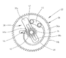
さらに、この機構は、プレート8上で回転可能に搭載された中間車列32を含む。この中間車列32は図2及び図3に詳細に図示されている。中間車列32は、その一端に歯34bを備えたスリーブ34aで形成された小歯車34を備えている。スリーブ34aは、円筒状部分34c及び円錐状部分34dから成り、円筒状部分34c及び円錐状部分34dは円筒状部分34cから外側に向かって広がっている。
Further, this mechanism includes an
中間車列32は、プレート36aから成る車36をさらに備えている。プレート36aの周縁は差動歯車装置18の心軸20に噛合する歯36bを備えている。スペーサ37は、スリーブ34aの円筒状部分34cに嵌め込まれている。車36は、スペーサ37に回転自在に装着され、したがって、小歯車34上で回転可能になっている。
The
この発明によれば、長方形の形状をなし、車36の直径に対して約0.75倍の長さを有するレバー38は、長手方向に延在するスリット41を備えている。このスリット41は、その長さのほぼ三分の二のところに位置する開口42へと広がっている。したがって、レバー38は、開口42のいずれか一方の側に、大アーム38a及び小アーム38bを有している。レバー38は、小歯車34の円錐状部分34d上に固定された留め金であり、車36を軸方向に固定する。このようにして、小歯車34及びレバー38は摩擦機構を形成し、その閾値偶力(threshold couple)はアーム38a及びアーム38bの弾性力によって規定される。
According to the present invention, the
さらに、約270°の角度にわたる円弧状の弾性ストリップからなるスプリング40は、その一端部44を介して、公知の手段で、車36のプレートに固定されている。自由端である、スプリング40の他端部46は、肘部46aに成っている。この肘部46aは、車36の外側に向かって屈曲し、かつ、休止状態においては、開口42の近傍で長アーム38aに接して配置されている。したがって、他端部46は、レバーを弾性ストリップの端部44に向かって押圧した状態を保持している。
Further, the
最後に、図1には、この機構が、プレート8に嵌め込まれた回動軸50に回転可能に装着された表示器用車列48を含んでいることが示されている。表示器用車列48は、周縁に小歯車34に噛合する歯48bを備えたプレート48aと、プレート8の下部にまで延在し、図示しないパワーリザーブ表示器の針を回転駆動する管48cとを有している。
Finally, FIG. 1 shows that this mechanism includes a display vehicle train 48 that is rotatably mounted on a pivot shaft 50 fitted in the plate 8. The display train 48 includes a plate 48a having teeth 48b meshing with the
プレート48aは、パワーリザーブ表示器の針の移動角度に対応する約150°の角度にわたる輪環状の切欠部48dを有している。プレート8に嵌め込まれたピン52は、切欠部48dに係合して、車列48の停止部材として機能し、このようにして、車列48用の、第1の終端位置及び第2の終端位置が規定される。 The plate 48a has an annular notch 48d extending over an angle of about 150 ° corresponding to the angle of movement of the needle of the power reserve indicator. The pin 52 fitted in the plate 8 engages with the notch 48d and functions as a stop member for the train 48, and thus the first end position and the second end for the train 48. A position is defined.
以上説明した機構を備えた腕時計用ムーブメントにおいては、主ゼンマイ14は、緩んでいる間は、従来のように、輪列に噛合する香箱10を回転駆動する。
In the wristwatch movement having the mechanism described above, the
前記欧州特許出願には、主ゼンマイ14の巻き上げ中及び緩み中における差動歯車装置18の動作が詳細に記載されている。したがって、本明細書では、再度説明する必要はないであろう。
The European patent application describes in detail the operation of the differential gear unit 18 during winding and loosening of the
通常の動作においては、すなわち、主ゼンマイがムーブメントの輪列を正確に駆動させるのに十分に巻き上げられ、かつ、表示器用車列がその2つの終端位置の間に構成されるときには、スプリング40は、その端部44と46aとで握持されたレバー38を、端部44を介して、駆動させる。
In normal operation, i.e., when the main spring is sufficiently rolled up to accurately drive the movement train wheel and the indicator train is configured between its two end positions, the
主ゼンマイ14は、輪列を駆動させるにつれて徐々に緩まる。図4に示すように、曲線58aで示される主ゼンマイの偶力(couple)は、閾値60aに達するまで減少する。
The
次いで、パワーリザーブ表示機構は、偶力が使い果たされたことを表示し、表示器用車列が固定されて、切欠部48dの端部はピン52で停止する。 Next, the power reserve display mechanism displays that the couple has been used up, the display vehicle train is fixed, and the end of the notch 48d stops at the pin 52.
前記欧州特許出願に記載された機構のように、腕時計の使用者が主ゼンマイを未だ巻き上げていない場合には、腕時計ムーブメントが駆動している間、主ゼンマイは引き続き緩む。したがって、差動歯車装置18は、引き続き回転し、そのうえ、車36を回転させる。小歯車34は表示器用車列48に噛合しているから、小歯車34の回転は停止される。したがって、車36は小歯車34に対して相対的に移動する。車36は巻き上げられたスプリング40によって小歯車34に連結しているから、車36は相対的に移動可能になる。曲線62aで示されるように、スプリング40によって発生する偶力は、点64から、主ゼンマイ14とスプリング40との偶力が互いに相殺される点65まで増加し、その結果、腕時計が停止する。
If the watch user has not yet rolled up the mainspring, as in the mechanism described in the European patent application, the mainspring will continue to loosen while the watch movement is being driven. Accordingly, the differential gear unit 18 continues to rotate and, in addition, rotates the
次いで、使用者が主ゼンマイを、曲線58bに示されるように、巻き上げる。スプリング40が緩められ(曲線62b)、このようにして、レバー38がその休止位置に復帰すると、主ゼンマイの偶力は点60bのある値に到達し、表示器用車列は再度駆動されて、表示器は文字盤の目盛りに関して移動する。主ゼンマイの巻き上げによるこの作動中において、スプリング40の端部44は、小歯車34上のレバー38の摩擦偶力よりも小さな偶力でレバー38を駆動させ、このようにして、そのうえ小歯車34を駆動させる。次いで、パワーリザーブ表示器が最大負荷を表示すると、表示器用車列は固定される。主ゼンマイ14の対応する偶力は曲線58bにおける点66の位置で示される。その結果、小歯車34は表示器用車列48に噛合しているから、小歯車34の回転は停止される。
Next, the user rolls up the main spring as indicated by the curve 58b. When the
腕時計の使用者が主ゼンマイ14を巻き上げつづけると、使用者は、スリーブ34aに嵌め込まれたレバー38の、曲線58bの部分68で示される抵抗に打ち勝つ必要がある。次いで、スプリング40の端部44に接しているレバー38は、主ゼンマイ14の最大巻き上げ量まで、小歯車34上を回転する。この滑動バネシステムによれば、主ゼンマイ14の偶力は、巻き上げられているにもかかわらず、平坦域70で安定する。表示器機構の種々の要素は、完全に、調整され、又は、順応される。そして、この機構の構成要素が適所に装着されると、採用されるいかなる特別の手段を用いることなく、レバー及び表示器の終端位置と、主ゼンマイの最大巻き上げ量とが一致する。
As the watch user continues to wind up the
このように、主ゼンマイの緩みに続くサイクルが実行される。次いで、再度巻き上げられる間には、第1のサイクルで実現された調整によって、使用者は、表示器がその端部に到達するときに、主ゼンマイが完全に巻き上げられていることを、理解する。 In this way, a cycle following the loosening of the mainspring is executed. Then, while being rolled up again, the adjustment realized in the first cycle allows the user to understand that the main spring is fully rolled up when the indicator reaches its end. .
説明した装置においては、種々の要素を適所に装着するのに特別な手段は、作製及びアフターサービスのいずれの場合も、必要とされない。その理由は、巻き上げられている間はレバー38が小歯車34に摩擦しながら回転し、一方、緩む間は、スプリング40が巻かれているから調整が維持されているという事実によって、表示器はその適正な位置に自動的に調整されることにある。このような調整を可能にするため、スプリング40の巻き偶力は、常に、円錐部34dに嵌め込まれたレバー38の摩擦偶力よりも小さく保持される必要があることは、明白である。
In the apparatus described, no special means are required for mounting the various elements in place, both in production and after service. The reason for this is that the
Claims (7)
・車列(48)と、前記車列によって回転駆動される表示装置とを備えたパワーリザーブ表示器、
・第1の入力装置(26)を介して前記香箱(10)に運動学的に連結され、第2の入力装置(28)を介して前記巻き上げ手段に運動学的に連結され、かつ、出力装置(20)を介して前記パワーリザーブ表示器に運動学的に連結された、差動歯車装置(18)、並びに、
・第1の部品及び第2の部品と、このような部品に連結する連結部材とを含む中間車列(32)であって、
第1の部品及び第2の部品は前記出力装置(20)及び前記パワーリザーブ表示器の前記車列(48)にそれぞれ運動学的に連結され、かつ、
前記主ゼンマイ(14)の巻き上げ量が最大閾値よりも大きいときに達する第1の端部位置と、前記主ゼンマイ(14)の巻き上げ量が最小閾値よりも小さいときに達する第2の端部位置との間の位置を前記パワーリザーブ表示器が占め、前記主ゼンマイ(14)の巻き上げ量が前記最大閾値と前記最小閾値との間にあるときに、前記第1の部品と前記第2の部品とを回転可能に連結するように、配置されて成る中間車列(32)
を備えたタイプのタイムピースムーブメント用のパワーリザーブ表示機構において、
前記連結部材は、前記パワーリザーブ表示器が前記第1の端部位置に到達したときに、前記第1の部品が前記第2の部品に対して摩擦しつつ移動可能となるように配置された摩擦機構と、前記第2の部品に対して前記第1の部品が移動することによって、前記パワーリザーブ表示器が前記第2の端部位置に到達したときに、屈曲可能となるように配置された弾性要素(40)とを含有することを特徴とするパワーリザーブ表示機構。A power source comprising a frame, a barrel (10) and a mainspring (14) housed in the barrel, a train wheel driven by the barrel, and a winding means for the mainspring (14);
A power reserve indicator comprising a vehicle train (48) and a display device driven to rotate by the vehicle train;
-Kinematically connected to the barrel (10) via a first input device (26), kinematically connected to the hoisting means via a second input device (28), and output A differential gearing (18) kinematically coupled to the power reserve indicator via a device (20), and
An intermediate train (32) comprising a first part and a second part and a connecting member connected to such a part,
A first part and a second part are kinematically coupled to the output device (20) and the train (48) of the power reserve indicator, respectively; and
A first end position that is reached when the winding amount of the main spring (14) is larger than a maximum threshold value, and a second end position that is reached when the winding amount of the main spring (14) is smaller than a minimum threshold value The power reserve indicator occupies a position between the first part and the second part when the amount of winding of the main spring (14) is between the maximum threshold value and the minimum threshold value. And an intermediate train row (32) arranged so as to be rotatably connected to each other
In the power reserve display mechanism for the type of timepiece movement with
The connecting member is arranged such that when the power reserve indicator reaches the first end position, the first part can move while being rubbed against the second part. When the first component moves with respect to the friction mechanism and the second component, the power reserve indicator is arranged to be bendable when it reaches the second end position. A power reserve display mechanism comprising: an elastic element (40).
・前記パワーリザーブ表示器が前記第1の端部位置を占めて、前記主ゼンマイ(14)が巻き上げつづけられるときに、前記レバー(38)は、前記止め部材に対して固定され、固定される前記部品上を摩擦しつつ回転して、前記パワーリザーブ表示器は固定状態になり、
・前記主ゼンマイ(14)が緩み次第、前記パワーリザーブ表示器は、前記第1の端部位置から離れ、前記中間車列(32)の前記第1の部品及び前記第2の部品を共に回転するように、大きさが調整され、配置されていることを特徴とする請求項1に記載のパワーリザーブ表示機構。Said friction mechanism, said first and second fixed stop member on one of the parts (44), said first and second part of the lever which is mounted with a friction in the other (38) Including
- the power reserve indicator occupies before Symbol first end position, said main spiral spring (14) when the can continue winding up, the lever (38) is fixed relative to the stop member is fixed Rotating while rubbing on the parts, the power reserve indicator is in a fixed state,
-As soon as the mainspring (14) is loosened, the power reserve indicator moves away from the first end position and rotates both the first and second parts of the intermediate train (32). The power reserve display mechanism according to claim 1, wherein the power reserve display mechanism is adjusted and arranged.
前記第1及び第2の部品の内の前記止め部材(44)を含む方の部品に固定されると共に、前記パワーリザーブ表示器が前記第2の端部位置にあるときに、前記レバー(38)が固定される一方で、前記主ゼンマイ(14)が前記輪列及び前記差動歯車装置を駆動するように、前記レバー(38)と協働し、かつ、
前記主ゼンマイが緩むときに、前記弾性要素(40)は、屈曲されて、緩むことを特徴とする請求項2又は3に記載のパワーリザーブ表示機構。The elastic element (40)
Wherein is fixed to the first and part of the person the containing stop member (44) of the second part, when the power reserve indicator is in said second end position, the lever (38 ) Is fixed, while the mainspring (14) cooperates with the lever (38) to drive the train wheel and the differential gear, and
The power reserve display mechanism according to claim 2 or 3, wherein when the main spring is loosened, the elastic element (40) is bent and loosened.
周縁に歯(36b)を備えたプレート(36a)から成る車(36)、一端部に歯(34b)を備えたスリーブ(34a)から成る小歯車(34)、前記スリーブ(34a)上に配置されたスペーサ(37)、及び、前記スリーブ(34a)に固着され、前記車(36)を前記スペーサ(37)上を自由に回転させる前記レバーを備えることを特徴とし、かつ、前記出力装置(20)に連結された前記部品は前記車(36)であることを特徴とする請求項1〜5のいずれか1項に記載のパワーリザーブ表示機構。The intermediate train row (32)
A wheel (36) consisting of a plate (36a) with teeth (36b) on the periphery, a small gear (34) consisting of a sleeve (34a) with teeth (34b) at one end, arranged on the sleeve (34a) And a spacer (37) fixed to the sleeve (34a) and the lever for freely rotating the wheel (36) on the spacer (37), and the output device ( The power reserve display mechanism according to any one of claims 1 to 5, wherein the component connected to 20) is the vehicle (36).
Applications Claiming Priority (2)
| Application Number | Priority Date | Filing Date | Title |
|---|---|---|---|
| EP04002419A EP1562086B1 (en) | 2004-02-04 | 2004-02-04 | Power reserve indicator mechanism |
| PCT/IB2005/000019 WO2005085963A1 (en) | 2004-02-04 | 2005-01-07 | Run reserve device indicating |
Publications (2)
| Publication Number | Publication Date |
|---|---|
| JP2007520717A JP2007520717A (en) | 2007-07-26 |
| JP4566201B2 true JP4566201B2 (en) | 2010-10-20 |
Family
ID=34673668
Family Applications (1)
| Application Number | Title | Priority Date | Filing Date |
|---|---|---|---|
| JP2006551939A Expired - Fee Related JP4566201B2 (en) | 2004-02-04 | 2005-01-07 | Power reserve display mechanism |
Country Status (9)
| Country | Link |
|---|---|
| US (1) | US7684285B2 (en) |
| EP (2) | EP1562086B1 (en) |
| JP (1) | JP4566201B2 (en) |
| CN (1) | CN100524097C (en) |
| AT (1) | ATE534939T1 (en) |
| HK (1) | HK1076876A1 (en) |
| MY (1) | MY140197A (en) |
| TW (1) | TW200535577A (en) |
| WO (1) | WO2005085963A1 (en) |
Families Citing this family (8)
| Publication number | Priority date | Publication date | Assignee | Title |
|---|---|---|---|---|
| RU2526560C2 (en) * | 2012-11-27 | 2014-08-27 | Общество с ограниченной ответственностью "Константин Чайкин" | Device, clock with device and shabbat time indication method |
| EP2977828B1 (en) * | 2014-07-21 | 2017-08-30 | ETA SA Manufacture Horlogère Suisse | Timepiece power reserve indicator |
| EP3232274A1 (en) * | 2015-01-05 | 2017-10-18 | Citizen Watch Co., Ltd. | Movement for mechanical timepiece |
| CN106502076B (en) * | 2015-09-07 | 2017-12-22 | 天津海鸥表业集团有限公司 | Display mechanism of power reserve |
| EP3333637B1 (en) * | 2016-12-12 | 2021-09-22 | ETA SA Manufacture Horlogère Suisse | Mechanical clock movement with power reserve detection |
| EP3699694B1 (en) * | 2019-02-21 | 2022-10-26 | Patek Philippe SA Genève | Timepiece including a device for displaying power reserve |
| CN111860021B (en) * | 2020-07-29 | 2022-11-29 | 广西科技大学 | Data calling equipment |
| EP4343449A1 (en) | 2022-09-26 | 2024-03-27 | Oris Holding AG | Power reserve indicator |
Family Cites Families (11)
| Publication number | Priority date | Publication date | Assignee | Title |
|---|---|---|---|---|
| CH688879B5 (en) * | 1995-08-10 | 1998-11-13 | Asulab Sa | Timepiece with indication of the power reserve. |
| CH690973A5 (en) * | 1996-12-19 | 2001-03-15 | Asulab Sa | Timepiece whose mechanism is driven by mechanical means and including a power reserve indicator device. |
| JPH11183642A (en) * | 1997-12-22 | 1999-07-09 | Seiko Instruments Inc | Clock with device displaying wound state of spring |
| CN1249449A (en) * | 1998-09-30 | 2000-04-05 | 东方时计株式会社 | Indication mechanism of spiral spring power and clocks and watches |
| EP1074897B1 (en) * | 1999-08-04 | 2009-04-15 | Frédéric Piguet S.A. | Device for displaying the power-reserve of a timepiece |
| JP3460688B2 (en) * | 1999-09-29 | 2003-10-27 | セイコーエプソン株式会社 | Timing device |
| DE60036603T2 (en) * | 2000-03-27 | 2008-07-03 | Vaucher Manufacture Fleurier S.A. | Display mechanism of the power reserve of a watch and clock provided with this mechanism |
| EP1260883A1 (en) * | 2001-05-22 | 2002-11-27 | Parmigiani Mesure et Art du Temps SA | Winding state indicator device |
| US6826124B2 (en) * | 2002-12-04 | 2004-11-30 | Asulab S.A. | Timepiece with power reserve indication |
| EP1498789A1 (en) * | 2003-07-14 | 2005-01-19 | Eterna SA | Winding state indicator mechanism for a mechanical timepiece |
| JP4475630B2 (en) * | 2004-01-27 | 2010-06-09 | セイコーインスツル株式会社 | Timepiece with mainspring winding state display including a deformed segment gear |
-
2004
- 2004-02-04 AT AT04002419T patent/ATE534939T1/en active
- 2004-02-04 EP EP04002419A patent/EP1562086B1/en not_active Expired - Lifetime
-
2005
- 2005-01-07 CN CNB2005800040525A patent/CN100524097C/en not_active Expired - Fee Related
- 2005-01-07 EP EP05702190A patent/EP1711865A1/en not_active Withdrawn
- 2005-01-07 US US10/596,937 patent/US7684285B2/en not_active Expired - Fee Related
- 2005-01-07 WO PCT/IB2005/000019 patent/WO2005085963A1/en not_active Application Discontinuation
- 2005-01-07 JP JP2006551939A patent/JP4566201B2/en not_active Expired - Fee Related
- 2005-01-20 TW TW094101619A patent/TW200535577A/en unknown
- 2005-02-03 MY MYPI20050418A patent/MY140197A/en unknown
- 2005-12-06 HK HK05111163.3A patent/HK1076876A1/en not_active IP Right Cessation
Also Published As
| Publication number | Publication date |
|---|---|
| EP1562086A1 (en) | 2005-08-10 |
| HK1076876A1 (en) | 2006-01-27 |
| CN1914565A (en) | 2007-02-14 |
| CN100524097C (en) | 2009-08-05 |
| US20090161495A1 (en) | 2009-06-25 |
| TW200535577A (en) | 2005-11-01 |
| WO2005085963A1 (en) | 2005-09-15 |
| MY140197A (en) | 2009-11-30 |
| US7684285B2 (en) | 2010-03-23 |
| ATE534939T1 (en) | 2011-12-15 |
| EP1711865A1 (en) | 2006-10-18 |
| JP2007520717A (en) | 2007-07-26 |
| EP1562086B1 (en) | 2011-11-23 |
Similar Documents
| Publication | Publication Date | Title |
|---|---|---|
| JP4566201B2 (en) | Power reserve display mechanism | |
| JP5255008B2 (en) | Clock with chronograph and watch | |
| US7490977B2 (en) | Timepiece including a power reserve indicator device | |
| JP4505054B2 (en) | Device comprising a watch movement and a chronograph module | |
| JP5351916B2 (en) | Power reserve display device integrated with a rotating weight, and a rotating weight for a self-winding watch equipped with the power reserve display device | |
| US7320543B2 (en) | Timepiece including a striking mechanism with instantaneous release | |
| US7322742B2 (en) | Timepiece with a striking mechanism comprising a single barrel | |
| US8760975B2 (en) | Timepiece furnished with a device for displaying determined time periods | |
| JP5145323B2 (en) | Watch movement with retrograde display | |
| JP4671477B2 (en) | Clock power holding amount display device | |
| JP4631839B2 (en) | clock | |
| JP5030091B2 (en) | Clock with improved time setting device | |
| JP2010507087A (en) | Clock hands, movements and timepieces that drive hands | |
| JP4508451B2 (en) | Storage power indicator mechanism and timepiece having the mechanism | |
| JP6180231B2 (en) | Watch movement with power reserve for extended operation | |
| JP5467056B2 (en) | Watch with chronograph mechanism | |
| JP5320368B2 (en) | clock | |
| US8506157B2 (en) | Uncoupling device for a timepiece mechanism and a watch movement comprising the same | |
| JP2009122107A (en) | Toothed wheel for timepiece, corresponding gear system, and timepiece movement | |
| JP7135914B2 (en) | clock | |
| JP5933978B2 (en) | Timepiece with time zone display corresponding to the selected time | |
| JP4622274B2 (en) | Spring remaining amount display mechanism and clock | |
| JP2011164052A (en) | Spiral spring device and time piece | |
| US11868091B2 (en) | Watch | |
| JP3054943B2 (en) | Clock forward / reverse mechanism and power reserve mechanism using the same |
Legal Events
| Date | Code | Title | Description |
|---|---|---|---|
| A621 | Written request for application examination |
Free format text: JAPANESE INTERMEDIATE CODE: A621 Effective date: 20071214 |
|
| A131 | Notification of reasons for refusal |
Free format text: JAPANESE INTERMEDIATE CODE: A131 Effective date: 20100305 |
|
| A521 | Request for written amendment filed |
Free format text: JAPANESE INTERMEDIATE CODE: A523 Effective date: 20100527 |
|
| TRDD | Decision of grant or rejection written | ||
| A01 | Written decision to grant a patent or to grant a registration (utility model) |
Free format text: JAPANESE INTERMEDIATE CODE: A01 Effective date: 20100709 |
|
| A01 | Written decision to grant a patent or to grant a registration (utility model) |
Free format text: JAPANESE INTERMEDIATE CODE: A01 |
|
| A61 | First payment of annual fees (during grant procedure) |
Free format text: JAPANESE INTERMEDIATE CODE: A61 Effective date: 20100803 |
|
| R150 | Certificate of patent or registration of utility model |
Free format text: JAPANESE INTERMEDIATE CODE: R150 |
|
| FPAY | Renewal fee payment (event date is renewal date of database) |
Free format text: PAYMENT UNTIL: 20130813 Year of fee payment: 3 |
|
| LAPS | Cancellation because of no payment of annual fees |