EP3699694B1 - Timepiece including a device for displaying power reserve - Google Patents
Timepiece including a device for displaying power reserve Download PDFInfo
- Publication number
- EP3699694B1 EP3699694B1 EP19158502.5A EP19158502A EP3699694B1 EP 3699694 B1 EP3699694 B1 EP 3699694B1 EP 19158502 A EP19158502 A EP 19158502A EP 3699694 B1 EP3699694 B1 EP 3699694B1
- Authority
- EP
- European Patent Office
- Prior art keywords
- power reserve
- timepiece
- central base
- value
- driving wheel
- Prior art date
- Legal status (The legal status is an assumption and is not a legal conclusion. Google has not performed a legal analysis and makes no representation as to the accuracy of the status listed.)
- Active
Links
- 230000008878 coupling Effects 0.000 claims description 15
- 238000010168 coupling process Methods 0.000 claims description 15
- 238000005859 coupling reaction Methods 0.000 claims description 15
- 238000004804 winding Methods 0.000 claims description 11
- 238000010276 construction Methods 0.000 description 1
- 230000007423 decrease Effects 0.000 description 1
- 210000000056 organ Anatomy 0.000 description 1
- 230000002787 reinforcement Effects 0.000 description 1
Images


Classifications
-
- G—PHYSICS
- G04—HOROLOGY
- G04B—MECHANICALLY-DRIVEN CLOCKS OR WATCHES; MECHANICAL PARTS OF CLOCKS OR WATCHES IN GENERAL; TIME PIECES USING THE POSITION OF THE SUN, MOON OR STARS
- G04B9/00—Supervision of the state of winding, e.g. indicating the amount of winding
- G04B9/005—Supervision of the state of winding, e.g. indicating the amount of winding by optical indication of the amount of winding
-
- G—PHYSICS
- G04—HOROLOGY
- G04B—MECHANICALLY-DRIVEN CLOCKS OR WATCHES; MECHANICAL PARTS OF CLOCKS OR WATCHES IN GENERAL; TIME PIECES USING THE POSITION OF THE SUN, MOON OR STARS
- G04B47/00—Time-pieces combined with other articles which do not interfere with the running or the time-keeping of the time-piece
- G04B47/06—Time-pieces combined with other articles which do not interfere with the running or the time-keeping of the time-piece with attached measuring instruments, e.g. pedometer, barometer, thermometer or compass
- G04B47/066—Time-pieces combined with other articles which do not interfere with the running or the time-keeping of the time-piece with attached measuring instruments, e.g. pedometer, barometer, thermometer or compass with a pressure sensor
-
- G—PHYSICS
- G04—HOROLOGY
- G04B—MECHANICALLY-DRIVEN CLOCKS OR WATCHES; MECHANICAL PARTS OF CLOCKS OR WATCHES IN GENERAL; TIME PIECES USING THE POSITION OF THE SUN, MOON OR STARS
- G04B47/00—Time-pieces combined with other articles which do not interfere with the running or the time-keeping of the time-piece
- G04B47/06—Time-pieces combined with other articles which do not interfere with the running or the time-keeping of the time-piece with attached measuring instruments, e.g. pedometer, barometer, thermometer or compass
- G04B47/068—Time-pieces combined with other articles which do not interfere with the running or the time-keeping of the time-piece with attached measuring instruments, e.g. pedometer, barometer, thermometer or compass with a thermometer
Definitions
- the present invention relates to a timepiece comprising a device for displaying the power reserve of an energy source of the timepiece, comprising a first element consisting of a member for displaying the values of said reserve of power, in particular in the form of a circular sector, and a second element consisting of an index arranged to indicate on the display member a value of said power reserve, one of the first and second elements being fixed and the other being mobile in rotation, said power reserve being able to vary between a minimum possible value and a maximum possible value.
- Such a type of display device can be used in a timepiece for example to display the power reserve of a barrel supplying energy to said timepiece.
- the movement of a timepiece designed to operate for one month has a theoretical power reserve generally estimated at between 32 and 40 days depending on the torque taken and the torques of the barrel springs equipping the timepiece.
- the power reserve on the dial should therefore show only 30 days of operation while the barrel springs continue to disarm so that the power reserve actually shows more than 30 days of operation. The risk is that the movement goes into “degraded” mode.
- Another solution consists of integrating a stop mechanism on the barrel into the movement.
- a stop mechanism on the barrel into the movement.
- such a mechanism is complex to implement.
- the wheel carrying the power reserve index comprises a stop in the high position which makes it possible to precisely define its position.
- the wheel carrying the power reserve index comes into contact with the stop and friction (arm friction, lanterning) is provided to "deactivate” said wheel and thus avoid display false information.
- this system requires the provision of a sliding flange on the barrel spring so as not to desynchronize the information on the power reserve.
- the patent application CH 711 236 discloses a power reserve display mechanism comprising a display board, a drive wheel mounted on the display board, the barrel carrying the power reserve hand passing through the drive wheel.
- the display board and the drive wheel are connected in rotation by a spring whose inner end is fixed to the center of the drive wheel and the outer end is fixed to the outer periphery of the display board , with a maximum angular movement defined so that the power reserve hand is stopped on the minimum scale when the power reserve passes a threshold from which the energy is no longer sufficient to guarantee satisfactory rate precision.
- the remaining days of “low” reserve are not displayed on the dial.
- the mechanism is also designed so that 100% of the scale displayed on the dial corresponds to the maximum winding of the mainspring.
- the drive wheel must have a certain diameter to respect the relationship with the input mobile and the display board and the drive wheel are of substantially identical diameters in order to be able to position a spiral spring having the dimensions required for the proper functioning of the mechanism.
- This display device requiring the superposition of three elements (display board, drive wheel and spring) of substantially the same dimensions is therefore relatively bulky.
- the display device described in the application CH 711 236 displays 100% of the graduation corresponding to the maximum reinforcement.
- the maximum winding is not actually reached when the needle indicates 100%, hence a risk of misleading the user.
- the maximum winding is exceeded when the needle indicates 100%, hence a risk of breaking the mainspring.
- the present invention aims to remedy these drawbacks by proposing a power reserve display device making it possible to display said power reserve over a defined operating range, independently of variations at the start and end of operation.
- the present invention aims to propose a power reserve display device making it possible to display the power reserve over a range of determined values, different from the theoretical maximum winding and total unwinding, and to eliminate the positioning fault. of the power reserve index, without the aid of a complex stopping mechanism, or of friction and sliding flange.
- the present invention also aims to propose a power reserve display device making it possible to occupy a small volume in the already limited space of a timepiece movement of a timepiece, such as a wristwatch.
- the present invention relates to a timepiece comprising a device for displaying the power reserve of an energy source of the timepiece comprising a first element consisting of a value display member of said power reserve and a second element consisting of an index arranged to indicate on the display member a value of said power reserve, one of the first and second elements being fixed and the other being mobile in rotation, said power reserve being able to vary between a minimum possible value and a maximum possible value.
- the display device comprises a drive wheel arranged to receive a power reserve value, a central base mounted free to rotate concentrically on the drive wheel, said central base carrying the first or second element which is movable in rotation, and an elastic coupling element, a first end of which is fixed to the central base and a second end is fixed to the driving wheel, the elastic coupling element being arranged to connect the said driving wheel and the said central base only in rotation when the power reserve evolves within a range delimited by a determined minimum value and a determined maximum value, between the minimum possible value and the maximum possible value, and to separate the drive wheel from the central base when the power reserve is out of said beach.
- the display device makes it possible to display the power reserve only within a determined range, independently of the minimum and maximum possible values.
- the positioning errors and uncertainties of the index relative to the graduations on the display member at the start and end of operation are eliminated.
- the central base preferably having smaller dimensions, and preferably much smaller, than those of the drive wheel, allows a significant and appreciable gain in volume.
- the central base carries a pin and there is provided, on a frame of the timepiece, a first abutment and a second abutment, said first abutment and second abutment being arranged so that, while the base central and the drive wheel are integral in rotation, the pin abuts against said first stop when the determined minimum value is reached and abuts against said second stop when the determined maximum value is reached.
- a first loop concentric with the central base and in which said pin can circulate when the central base and the drive wheel are integral in rotation, the length of said first loop being chosen so that a first end of the first loop constitutes the first abutment and a second end of the first loop constitutes the second abutment.
- the pin is arranged to pass through and emerge from the drive wheel, and the drive wheel comprises a second concentric loop superimposed on the first loop, in which said pin can circulate when the drive wheel is disengaged in rotation of the central plinth.
- the length of the second loop can be chosen so that the pin abuts against a first end of the second loop when the minimum possible value of the power reserve is reached and against a second end of the second loop when the maximum possible value of the power reserve is reached.
- the second end of the elastic coupling element can be fixed to the outer periphery of the drive wheel.
- the drive wheel is kinematically linked to said energy source to be able to rotate in a first direction when the energy source is armed and in a second direction when disarmed. of the energy source.
- the elastic coupling element is a spring, and preferably a spiral spring.
- the display member may comprise graduations according to which the minimum graduation displayed corresponds to the determined minimum value and the displayed maximum scale corresponds to the determined maximum value.
- the display member may comprise graduations offset with respect to the actual value of the power reserve so that the minimum graduation displayed is "0" when the actual values of the power reserve are less than or equal to the determined minimum value and the maximum graduation displayed is equal to the determined maximum value minus the determined minimum value when the actual values of the power reserve are greater than or equal to the determined maximum value.
- the present invention relates to a device for displaying a timepiece arranged to display on a display member, such as a dial, information that can vary between a minimum possible value and a maximum possible value.
- This information relates to the power reserve of an energy source, such as a barrel, of the timepiece.
- a device 1 for displaying the power reserve of a barrel comprising a first element consisting of a display member 2, such as a dial, advantageously in the form of a circular sector, and a second element constituted by an index 4, such as a hand or an indicator disc, arranged to indicate on the display member 2 a value of the power reserve.
- a display member 2 such as a dial
- an index 4 such as a hand or an indicator disc
- the display member 2 is fixed and the index 4 is rotatable, and is arranged to move opposite the display member 2 to display a value of the power reserve within a determined range, as will be described below.
- the display device 1 comprises a drive wheel 6 arranged to receive an instantaneous value of the power reserve.
- the drive wheel is toothed and meshes with the pinion 8 of a mobile 10 kinematically linked to the energy source, such as a barrel, to be able to rotate in a first direction, here in the opposite direction. clockwise, when arming the energy source, and to be rotatable in a second direction, here clockwise, when disarming the energy source .
- the display device 1 also comprises a central base 12 mounted free to rotate concentrically on the drive wheel 6.
- the central base 12 is preferably circular in shape. It comprises a barrel 12a arranged concentrically around a barrel 6a provided on the driving wheel 6. This means that seen from the dial side, the central base 12 is arranged above the driving wheel 6. At the end of the barrel 12a is fixed index 4 (or the display member if it is the latter which is rotatable, the index then being fixed).
- the central base 12 has dimensions different from those of the drive wheel 6, these dimensions being preferably smaller, and preferably much smaller, than those of the drive wheel 6, in order to obtain a significant gain in volume.
- the central base 12 comprises a lug 12b projecting radially in the plane of the central base 12, perpendicular to the barrel 12a.
- Ear 12b carries a pin 14 whose role will be described below.
- the display device also comprises an elastic coupling element 16 of which a first end 16a, that is to say the inner end, is fixed to the base of the lug 12b of the central base 12, and a second end 16b, that is to say the outer end, is fixed to the drive wheel 6.
- the central base 12 with its lug 12b is made in one piece with the elastic coupling element 16.
- the second end 16b of the elastic coupling element 16 is fixed to the outer periphery of the drive wheel 6 by means of a fixing stud 18 integral with the drive wheel 6 and around which is mounted an eyelet 20 provided to the second end 16b of the elastic coupling element 16.
- the elastic coupling element 16 is a spring, and more preferably a spiral spring.
- the elastic coupling element 16 is arranged to connect the drive wheel 6 and the central base 12 in rotation only when the power reserve evolves within a range delimited by a determined minimum value and a determined maximum value. , between the minimum possible power reserve value and the maximum possible power reserve value, and to separate the drive wheel 6 from the central base 12 when the power reserve is outside of said range, so that the drive wheel 6 can continue its rotation independently of the central base 12 when the power reserve is outside said range, without moving the index 4.
- the minimum and maximum values determined are different from the minimum and maximum possible values respectively.
- a first abutment and a second abutment are arranged so that, when the central base 12 and the drive wheel 6 are integral in rotation, the power reserve being within the range delimited by the determined minimum value and the determined maximum value, the pin 14 carried by the central base 12 abuts against the first stop when the determined minimum value of the power reserve gear is reached and abuts against the second stop when the determined maximum value of the power reserve is reached.
- the pin 14 is arranged to project in the direction of the driving wheel 6, and to pass through and emerge from the said driving wheel 6, the said frame then being located under the driving wheel 6, seen from the dial side.
- the frame has a first loop or slot 22 concentric with the central base 12 as shown in the figures 4 to 7 .
- the first loop 22 is positioned relative to the central base 12 so that the pin 14 carried by the central base 12 can circulate in the first loop 22 when the central base 12 and the drive wheel 6 are integral in rotation, the power reserve lying within the range bounded by the determined minimum value and the determined maximum value.
- the length of the first loop 22 is chosen so that a first end 22a of the first loop 22 constitutes the first stop, at the moment when the determined minimum value of the power reserve is reached, and that a second end 22b of the first loop 22 constitutes the second stop, when the determined maximum value of the power reserve is reached.
- the drive wheel 6 comprises a second loop 24, positioned so as to be concentric and superimposed on the first loop 22 provided on the frame and so that the pin 14 carried by the central base 12 passes through the second loop 24 and can circulate therein when the driving wheel 6 is disconnected in rotation from the central base 12 and continues to rotate, the power reserve being outside the range bounded by the determined minimum value and the determined maximum value.
- the length of the second loop 24 is chosen so that the pin 14 abuts against a first end 24a of the second loop 24, when the minimum possible value of the power reserve is reached, and abuts against a second end 24b of the second loop 24 when the maximum possible value of the power reserve is reached.
- This configuration is optional and is not necessary in the case of a power reserve, for example if the driving wheel stops by itself when the maximum possible value of the power reserve is reached at maximum winding of the barrel and when the minimum possible power reserve value is reached, the movement stops due to the complete unwinding of the barrel.
- the display member may include graduations according to which the displayed minimum graduation corresponds to the determined minimum value and the displayed maximum graduation corresponds to the determined maximum value.
- the display member 2 may comprise graduations offset with respect to the real value of the power reserve as represented on the figures 2 and 3 , so that the minimum scale displayed is "0" when the actual values of the power reserve are less than or equal to the minimum value determined and the maximum scale displayed is equal to the maximum value determined minus the minimum value determined when the values of the power reserve are greater than or equal to the determined maximum value.
- the minimum scale displayed is "0" when the actual values of the power reserve are less than or equal to the minimum value determined
- the maximum scale displayed is equal to the maximum value determined minus the minimum value determined when the values of the power reserve are greater than or equal to the determined maximum value.
- the power reserve is displayed over 30 days, the graduation "0" displayed corresponding to the power reserve values between 0 and 5 days, and the “30” graduation corresponding to the power reserve values between 35 and 40 days.
- the display is always clear and precise between 0 and 30 days, with no positioning fault of the index on the display member, because it always displays a power reserve of 30 days even if a watch at the other, the number of turns of the mainspring varies between maximum winding and complete winding.
- the operation of the power reserve display device is as follows: during normal operation of the timepiece, the mainspring of the barrel is progressively disarmed, so that the displayed value of the power reserve on the organ display 2 by the index 4 gradually decreases, the index 4 being rotatable in the direction of clockwise.
- the display device is then in the position shown in the figure 4 .
- the index 4 is here in the form of a disk secured to the barrel 12a of the central base 12 and having on its periphery a tip serving as an index.
- the drive wheel 6, driven by the pinion 8 of the mobile 10 kinematically linked to the barrel, rotates clockwise.
- the stiffness of the spiral spring 16 is such that the rotation of the driving wheel 6 on which the second end 16b of the spiral spring 16 is fixed causes the rotation in the same direction of the central base 12 to which the first end 16a of the spring is fixed.
- balance spring 16 The drive wheel 6 and the central base 12 are integral in rotation via said balance spring 16, as long as the value of the power reserve is included in the range delimited by the determined minimum value and the determined maximum value .
- the pin 14, moving with the drive wheel 6 is stationary with respect to the second loop 24, and moves clockwise in the first loop 22.
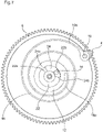
- the display device When the mainspring of the barrel continues to wind down and the power reserve reaches the determined minimum value, for example 5 days, 0 day being the minimum possible value, the display device is in the configuration represented on the figure 5 .
- the configuration of the display member 2 is such that the graduations are shifted so that the index 4 indicates the value 0 when the determined minimum value of 5 days has been reached or is exceeded, as shown in the picture 3 . Due to the length of the first loop 22, the pin 14 abuts against the first end 22a of the loop 22 so that any subsequent rotation of the central base 12 in the clockwise direction is prevented.
- the driving wheel 6 continues to turn clockwise and separates in rotation from the central base 12, blocked by the pin 14 in abutment against the end 22a of loop 22, as shown in figure 6 .
- Index 4 remains in its "0" position of the picture 3 to indicate that the determined minimum value has been reached.
- Drive wheel 6 can continue to rotate clockwise, second loop 24 being movable relative to pin 14. This causes coil spring 16 to wind, only its second end 16b moving with drive wheel 6, its first end 16a, fixed to the central base 12, being stationary.
- the drive wheel 6 can stop on its own if the barrel spring is completely unwinding or continue its rotation in the clockwise direction until the first end 24a of the second loop 24 abuts against the pin 14. The drive wheel 6 is then stopped, the minimum possible value of the power reserve being reached. Index 4 has remained fixed and continues to display that the determined minimum value of the power reserve has been reached.
- the drive wheel 6 When the user winds the barrel spring, the drive wheel 6 is driven in the counter-clockwise direction, the second loop 24 being able to rotate relative to the pin 14.
- the drive wheel 6 drives with it the second end 16b of spiral spring 16 which disarms.
- Said driving wheel 6 remains detached from the central base 12 until the spiral spring 16 returns to its normal configuration in which the driving wheel 6 is again integral in rotation with the central base 12 as long as the value of the power reserve is within the range bounded by the minimum value determined and the maximum value determined.
- the index 4 which had remained immobile can then move with the central base 12.
- the winding of the barrel being continued, the drive wheel 6 continues its rotation in the counterclockwise direction and causes with it the rotation of the central base 12 and of the index 4 also counterclockwise.
- the pin 14, moving with the drive wheel 6 is stationary relative to the second loop 24, and moves counterclockwise in the first loop 22.
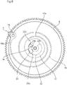
- the display device is then in the configuration represented on the figure 7 .
- the index 4 indicates the value "30" when the determined maximum value of 35 days has been reached or is exceeded, as shown in figure 2 . Due to the length of the first loop 22, the pin 14 abuts against the second end 22b of the loop 22 so that any subsequent rotation of the central base 12 counterclockwise is prevented.
- the drive wheel 6 continues to turn counterclockwise and separates in rotation from the central base 12, blocked by the pin 14 in abutment against the end 22b of the loop 22, as shown in the figure 8 .
- Index 4 remains in its "30" position of the figure 2 to indicate that the determined maximum value has been reached.
- Drive wheel 6 can continue to rotate counterclockwise, second loop 24 being rotatable relative to pin 14. This causes spiral spring 16 to wind, only its second end 16b moving with drive wheel 6 , its first end 16a, fixed to the central base 12, being stationary.
- the drive wheel 6 can stop by itself if the winding of the mainspring of the barrel is complete or continue its rotation in the counterclockwise direction until the second end 24b of the second loop 24 abuts against pin 14. Drive wheel 6 is then stopped, the maximum possible value of the power reserve being reached. Index 4 has remained fixed and continues to display that the determined maximum value of the power reserve has been reached.
- the display device used in the present invention makes it possible to precisely display an instantaneous value of the power reserve when said instantaneous value is comprised within a range delimited by a determined minimum value and a determined maximum value, and to remain on the determined minimum value when the instantaneous value of the power reserve reaches or becomes lower than this determined minimum value and on the determined maximum value when the instantaneous value of the power reserve reaches or becomes higher than this determined maximum value.
- the display device makes it possible to display the power reserve precisely over a range of determined values, by absorbing the variable strokes of the drive wheel 6.
- the present invention thus makes it possible to display the power reserve over a determined number of days, independently of the variable strokes of the drive wheel at the start of winding and at the end of unwinding.
- the display device used in the invention also makes it possible to display the range of values of one's choice.
- the power reserve one could choose to display the power reserve between 1 day and 31 days if one wishes to keep a display over 30 days.
- the display device used in the invention also allows a significant gain in volume.
- the use of the central base 12 arranged above the drive wheel 6 allows a volume gain of about 10% compared to the construction described in the application. CH 711 236 , which represents an interesting gain for the manufacturer.
- the pin 14 could project upwards, in the direction of the dial and be arranged to circulate in a groove provided on the underside of a bridge positioned above the central base 12, the groove being of length appropriate so that its ends constitute the first and second stops corresponding to the determined minimum and maximum values.
- the drive wheel held in position by its barrel held by a bridge or by a bridge, can continue to rotate relative to the base without requiring a loop for the circulation of the pin.
Description
La présente invention concerne une pièce d'horlogerie comprenant un dispositif d'affichage de la réserve de marche d'une source d'énergie de la pièce d'horlogerie, comprenant un premier élément constitué par un organe d'affichage des valeurs de ladite réserve de marche, notamment sous la forme d'un secteur circulaire, et un deuxième élément constitué par un index agencé pour indiquer sur l'organe d'affichage une valeur de ladite réserve de marche, l'un des premier et deuxième éléments étant fixe et l'autre étant mobile en rotation, ladite réserve de marche pouvant évoluer entre une valeur minimale possible et une valeur maximale possible.The present invention relates to a timepiece comprising a device for displaying the power reserve of an energy source of the timepiece, comprising a first element consisting of a member for displaying the values of said reserve of power, in particular in the form of a circular sector, and a second element consisting of an index arranged to indicate on the display member a value of said power reserve, one of the first and second elements being fixed and the other being mobile in rotation, said power reserve being able to vary between a minimum possible value and a maximum possible value.
Un tel type de dispositif d'affichage peut être utilisé dans une pièce d'horlogerie par exemple pour afficher la réserve de marche d'un barillet alimentant en énergie ladite pièce d'horlogerie. Le mouvement d'une pièce d'horlogerie prévue pour fonctionner un mois possède une réserve de marche théorique estimée en général entre 32 et 40 jours selon les prises de couple et les couples des ressorts de barillet équipant la pièce d'horlogerie. La réserve de marche sur le cadran devrait donc afficher seulement 30 jours de fonctionnement alors que les ressorts de barillet continuent de se désarmer de sorte que la réserve de marche affiche en réalité plus de 30 jours de fonctionnement. Le risque est que le mouvement passe en mode « dégradé ».Such a type of display device can be used in a timepiece for example to display the power reserve of a barrel supplying energy to said timepiece. The movement of a timepiece designed to operate for one month has a theoretical power reserve generally estimated at between 32 and 40 days depending on the torque taken and the torques of the barrel springs equipping the timepiece. The power reserve on the dial should therefore show only 30 days of operation while the barrel springs continue to disarm so that the power reserve actually shows more than 30 days of operation. The risk is that the movement goes into “degraded” mode.
Pour résoudre ce problème, il a été proposé des systèmes de réglage direct permettant, lorsque le mouvement est désarmé, de poser l'index de réserve de marche et de le positionner sur le 0, puis de remonter à fond le mouvement. Avec cette solution, il est possible que l'index en position de réserve de marche haute ne soit pas exactement en face de la graduation correspondante. Généralement, les erreurs sont moyennées au moment de la pose de l'index.To solve this problem, direct adjustment systems have been proposed which make it possible, when the movement is unarmed, to set the power reserve index and position it on 0, then to fully wind the movement. With this solution, it is possible that the index in the upper power reserve position is not exactly opposite the corresponding scale. Generally, the errors are averaged at the time the index finger is placed.
Une autre solution consiste à intégrer au mouvement un mécanisme d'arrêtage sur le barillet. Toutefois, un tel mécanisme est complexe à mettre en œuvre.Another solution consists of integrating a stop mechanism on the barrel into the movement. However, such a mechanism is complex to implement.
Il a été également proposé des systèmes avec des frictions et des butées, dans lesquels la roue portant l'index de réserve de marche comprend une butée en position haute qui permet de définir précisément sa position. Quand le ressort de barillet est remonté manuellement au maximum, la roue portant l'index de réserve de marche vient en contact avec la butée et une friction (friction à bras, lanternage) est prévue pour « désactiver » ladite roue et ainsi éviter d'afficher une information fausse. Toutefois, ce système nécessite de prévoir une bride glissante sur le ressort de barillet afin de ne pas désynchroniser l'information sur la réserve de marche.Systems with frictions and stops have also been proposed, in which the wheel carrying the power reserve index comprises a stop in the high position which makes it possible to precisely define its position. When the mainspring is manually wound to the maximum, the wheel carrying the power reserve index comes into contact with the stop and friction (arm friction, lanterning) is provided to "deactivate" said wheel and thus avoid display false information. However, this system requires the provision of a sliding flange on the barrel spring so as not to desynchronize the information on the power reserve.
La demande de brevet
Dans ce mécanisme, la roue d'entrainement doit présenter un certain diamètre pour respecter le rapport avec le mobile d'entrée et la planche d'affichage et la roue d'entrainement sont de diamètres sensiblement identiques afin de pouvoir positionner un ressort spiral présentant les dimensions requises pour le bon fonctionnement du mécanisme. Ce dispositif d'affichage nécessitant la superposition de trois éléments (planche d'affichage, roue d'entrainement et ressort) de sensiblement mêmes dimensions est donc relativement volumineux.In this mechanism, the drive wheel must have a certain diameter to respect the relationship with the input mobile and the display board and the drive wheel are of substantially identical diameters in order to be able to position a spiral spring having the dimensions required for the proper functioning of the mechanism. This display device requiring the superposition of three elements (display board, drive wheel and spring) of substantially the same dimensions is therefore relatively bulky.
En outre, même s'il permet de masquer les jours de « basse » réserve, le dispositif d'affichage décrit dans la demande
La présente invention vise à remédier à ces inconvénients en proposant un dispositif d'affichage de réserve de marche permettant d'afficher ladite réserve de marche sur une plage définie de fonctionnement, indépendamment des variations en début et en fin de fonctionnement.The present invention aims to remedy these drawbacks by proposing a power reserve display device making it possible to display said power reserve over a defined operating range, independently of variations at the start and end of operation.
Notamment la présente invention vise à proposer un dispositif d'affichage de réserve de marche permettant d'afficher la réserve de marche sur une plage de valeurs déterminées, différentes de l'armage maximal et du désarmage total théoriques, et de supprimer le défaut de positionnement de l'index de réserve de marche, sans l'aide de mécanisme d'arrêtage complexe, ou de friction et bride glissante.In particular, the present invention aims to propose a power reserve display device making it possible to display the power reserve over a range of determined values, different from the theoretical maximum winding and total unwinding, and to eliminate the positioning fault. of the power reserve index, without the aid of a complex stopping mechanism, or of friction and sliding flange.
La présente invention vise également à proposer un dispositif d'affichage de réserve de marche permettant d'occuper un faible volume dans l'espace déjà restreint d'un mouvement horloger d'une pièce d'horlogerie, telle qu'une montre-bracelet.The present invention also aims to propose a power reserve display device making it possible to occupy a small volume in the already limited space of a timepiece movement of a timepiece, such as a wristwatch.
A cet effet, la présente invention concerne une pièce d'horlogerie comprenant un dispositif d'affichage de la réserve de marche d'une source d'énergie de la pièce d'horlogerie comprenant un premier élément constitué par un organe d'affichage des valeurs de ladite réserve de marche et un deuxième élément constitué par un index agencé pour indiquer sur l'organe d'affichage une valeur de ladite réserve de marche, l'un des premier et deuxième éléments étant fixe et l'autre étant mobile en rotation, ladite réserve de marche pouvant évoluer entre une valeur minimale possible et une valeur maximale possible.To this end, the present invention relates to a timepiece comprising a device for displaying the power reserve of an energy source of the timepiece comprising a first element consisting of a value display member of said power reserve and a second element consisting of an index arranged to indicate on the display member a value of said power reserve, one of the first and second elements being fixed and the other being mobile in rotation, said power reserve being able to vary between a minimum possible value and a maximum possible value.
Selon l'invention, le dispositif d'affichage comprend une roue menante agencée pour recevoir une valeur de la réserve de marche, un socle central monté libre en rotation concentriquement sur la roue menante, ledit socle central portant le premier ou deuxième élément qui est mobile en rotation, et un élément de couplage élastique dont une première extrémité est solidaire du socle central et une seconde extrémité est solidaire de la roue menante, l'élément de couplage élastique étant agencé pour lier solidairement en rotation ladite roue menante et ledit socle central uniquement lorsque la réserve de marche évolue dans une plage délimitée par une valeur minimale déterminée et une valeur maximale déterminée, comprises entre la valeur minimale possible et la valeur maximale possible, et pour désolidariser la roue menante du socle central lorsque la réserve de marche est en dehors de ladite plage.According to the invention, the display device comprises a drive wheel arranged to receive a power reserve value, a central base mounted free to rotate concentrically on the drive wheel, said central base carrying the first or second element which is movable in rotation, and an elastic coupling element, a first end of which is fixed to the central base and a second end is fixed to the driving wheel, the elastic coupling element being arranged to connect the said driving wheel and the said central base only in rotation when the power reserve evolves within a range delimited by a determined minimum value and a determined maximum value, between the minimum possible value and the maximum possible value, and to separate the drive wheel from the central base when the power reserve is out of said beach.
Ainsi, le dispositif d'affichage selon l'invention permet d'afficher la réserve de marche uniquement dans une plage déterminée, indépendamment des valeurs minimale et maximale possibles. Les erreurs et incertitudes de positionnement de l'index par rapport aux graduations sur l'organe d'affichage en début et en fin de fonctionnement sont supprimées.Thus, the display device according to the invention makes it possible to display the power reserve only within a determined range, independently of the minimum and maximum possible values. The positioning errors and uncertainties of the index relative to the graduations on the display member at the start and end of operation are eliminated.
En outre, le socle central présentant de préférence des dimensions inférieures, et préférentiellement très inférieures, à celles de la roue menante, permet un gain en volume important et appréciable.In addition, the central base preferably having smaller dimensions, and preferably much smaller, than those of the drive wheel, allows a significant and appreciable gain in volume.
D'une manière avantageuse, le socle central porte une goupille et il est prévu, sur un bâti de la pièce d'horlogerie, une première butée et une seconde butée, lesdites première butée et seconde butée étant agencées pour que, alors que le socle central et la roue menante sont solidaires en rotation, la goupille bute contre ladite première butée au moment où la valeur minimale déterminée est atteinte et bute contre ladite seconde butée au moment où la valeur maximale déterminée est atteinte.Advantageously, the central base carries a pin and there is provided, on a frame of the timepiece, a first abutment and a second abutment, said first abutment and second abutment being arranged so that, while the base central and the drive wheel are integral in rotation, the pin abuts against said first stop when the determined minimum value is reached and abuts against said second stop when the determined maximum value is reached.
De préférence, il est prévu, sur le bâti de la pièce d'horlogerie, une première ganse concentrique au socle central et dans laquelle ladite goupille peut circuler lorsque le socle central et la roue menante sont solidaires en rotation, la longueur de ladite première ganse étant choisie pour qu'une première extrémité de la première ganse constitue la première butée et qu'une seconde extrémité de la première ganse constitue la seconde butée.Preferably, there is provided, on the frame of the timepiece, a first loop concentric with the central base and in which said pin can circulate when the central base and the drive wheel are integral in rotation, the length of said first loop being chosen so that a first end of the first loop constitutes the first abutment and a second end of the first loop constitutes the second abutment.
D'une manière particulièrement avantageuse, la goupille est agencée pour traverser et déboucher de la roue menante, et la roue menante comprend une seconde ganse concentrique et superposée à la première ganse, dans laquelle ladite goupille peut circuler lorsque la roue menante est désolidarisée en rotation du socle central.In a particularly advantageous manner, the pin is arranged to pass through and emerge from the drive wheel, and the drive wheel comprises a second concentric loop superimposed on the first loop, in which said pin can circulate when the drive wheel is disengaged in rotation of the central plinth.
Selon les modes de réalisation, la longueur de la seconde ganse peut être choisie pour que la goupille bute contre une première extrémité de la seconde ganse au moment où la valeur minimale possible de la réserve de marche est atteinte et contre une seconde extrémité de la seconde ganse au moment où la valeur maximale possible de la réserve de marche est atteinte.According to the embodiments, the length of the second loop can be chosen so that the pin abuts against a first end of the second loop when the minimum possible value of the power reserve is reached and against a second end of the second loop when the maximum possible value of the power reserve is reached.
De préférence, la seconde extrémité de l'élément de couplage élastique peut être fixée à la périphérie externe de la roue menante.Preferably, the second end of the elastic coupling element can be fixed to the outer periphery of the drive wheel.
Selon une variante de réalisation de l'invention, la roue menante est liée cinématiquement à ladite source d'énergie pour être mobile en rotation dans un premier sens lors de l'armage de la source d'énergie et dans un second sens lors du désarmage de la source d'énergie.According to a variant embodiment of the invention, the drive wheel is kinematically linked to said energy source to be able to rotate in a first direction when the energy source is armed and in a second direction when disarmed. of the energy source.
Avantageusement, l'élément de couplage élastique est un ressort, et de préférence un ressort spiral.Advantageously, the elastic coupling element is a spring, and preferably a spiral spring.
Selon une variante de réalisation de l'invention, l'organe d'affichage peut comporter des graduations selon lesquelles la graduation minimale affichée correspond à la valeur minimale déterminée et la graduation maximale affichée correspond à la valeur maximale déterminée.According to a variant embodiment of the invention, the display member may comprise graduations according to which the minimum graduation displayed corresponds to the determined minimum value and the displayed maximum scale corresponds to the determined maximum value.
Selon une autre variante de réalisation de l'invention, l'organe d'affichage peut comporter des graduations décalées par rapport à la valeur réelle de la réserve de marche de sorte que la graduation minimale affichée est « 0 » lorsque les valeurs réelles de la réserve de marche sont inférieures ou égales à la valeur minimale déterminée et la graduation maximale affichée est égale à la valeur maximale déterminée moins la valeur minimale déterminée lorsque les valeurs réelles de la réserve de marche sont supérieures ou égales à la valeur maximale déterminée.According to another variant embodiment of the invention, the display member may comprise graduations offset with respect to the actual value of the power reserve so that the minimum graduation displayed is "0" when the actual values of the power reserve are less than or equal to the determined minimum value and the maximum graduation displayed is equal to the determined maximum value minus the determined minimum value when the actual values of the power reserve are greater than or equal to the determined maximum value.
D'autres caractéristiques et avantages de la présente invention apparaîtront à la lecture de la description détaillée suivante d'un mode de réalisation de l'invention, donné à titre d'exemple non limitatif, et faite en référence aux dessins annexés dans lesquels :
- la
figure 1 est une vue en perspective d'un dispositif d'affichage de réserve de marche selon l'invention ; - la
figure 2 représente une vue de l'organe d'affichage et de l'index affichant la valeur maximale déterminée ; - la
figure 3 représente une vue de l'organe d'affichage et de l'index affichant la valeur minimale déterminée ; et - les
figures 4 à 8 représentent différents états du dispositif d'affichage selon l'invention en fonction de la valeur de la réserve de marche affichée par l'index.
- the
figure 1 is a perspective view of a power reserve display device according to the invention; - the
picture 2 - the
picture 3 represents a view of the display member and of the index displaying the determined minimum value; and - them
figures 4 to 8 represent different states of the display device according to the invention as a function of the value of the power reserve displayed by the index.
La présente invention concerne un dispositif d'affichage d'une pièce d'horlogerie agencé pour afficher sur un organe d'affichage, tel qu'un cadran, une information pouvant varier entre une valeur minimale possible et une valeur maximale possible. Cette information est relative à la réserve de marche d'une source d'énergie, telle qu'un barillet, de la pièce d'horlogerie.The present invention relates to a device for displaying a timepiece arranged to display on a display member, such as a dial, information that can vary between a minimum possible value and a maximum possible value. This information relates to the power reserve of an energy source, such as a barrel, of the timepiece.
En référence aux
Dans la variante représentée ici, l'organe d'affichage 2 est fixe et l'index 4 est mobile en rotation, et est agencé pour se déplacer en regard de l'organe d'affichage 2 pour afficher une valeur de la réserve de marche dans une plage déterminée, comme cela sera décrit ci-après.In the variant shown here, the
Il est bien évident que dans une variante non représentée, cette configuration pourrait être inversée, l'index étant fixe et l'organe d'affichage 2 étant mobile en rotation.It is obvious that in a variant not shown, this configuration could be reversed, the index being fixed and the
Conformément à la présente invention, le dispositif d'affichage 1 comprend une roue menante 6 agencée pour recevoir une valeur instantanée de la réserve de marche. A cet effet, la roue menante est dentée et engrène avec le pignon 8 d'un mobile 10 lié cinématiquement à la source d'énergie, telle qu'un barillet, pour être mobile en rotation dans un premier sens, ici dans le sens inverse des aiguilles d'une montre, lors de l'armage de la source d'énergie, et pour être mobile en rotation dans un second sens, ici dans le sens des aiguilles d'une montre, lors du désarmage de la source d'énergie.In accordance with the present invention, the
Le dispositif d'affichage 1 comprend également un socle central 12 monté libre en rotation concentriquement sur la roue menante 6. Le socle central 12 est de préférence de forme circulaire. Il comprend un canon 12a disposé concentriquement autour d'un canon 6a prévu sur la roue menante 6. Cela signifie que vu côté cadran, le socle central 12 est disposé au-dessus de la roue menante 6. A l'extrémité du canon 12a est fixé l'index 4 (ou l'organe d'affichage si c'est ce dernier qui est mobile en rotation, l'index étant alors fixe). D'une manière avantageuse, le socle central 12 présente des dimensions différentes de celles de la roue menante 6, ces dimensions étant de préférence inférieures, et préférentiellement très inférieures, à celles de la roue menante 6, afin d'obtenir un gain en volume important.The
Le socle central 12 comprend une oreille 12b faisant saillie radialement dans le plan du socle central 12, perpendiculairement au canon 12a. L'oreille 12b porte une goupille 14 dont le rôle sera décrit ci-après.The
Le dispositif d'affichage comprend également un élément de couplage élastique 16 dont une première extrémité 16a, c'est-à-dire l'extrémité intérieure, est fixée à la base de l'oreille 12b du socle central 12, et une seconde extrémité 16b, c'est-à-dire l'extrémité extérieure, est fixée à la roue menante 6. De préférence, le socle central 12 avec son oreille 12b est réalisé d'une seule pièce avec l'élément de couplage élastique 16.The display device also comprises an
De préférence, la seconde extrémité 16b de l'élément de couplage élastique 16 est fixée à la périphérie externe de la roue menante 6 au moyen d'un tenon de fixation 18 solidaire de la roue menante 6 et autour duquel est monté un œillet 20 prévu à la seconde extrémité 16b de l'élément de couplage élastique 16.Preferably, the
De préférence, l'élément de couplage élastique 16 est un ressort, et plus préférentiellement un ressort spiral.Preferably, the
Conformément à l'invention, l'élément de couplage élastique 16 est agencé pour lier solidairement en rotation la roue menante 6 et le socle central 12 uniquement lorsque la réserve de marche évolue dans une plage délimitée par une valeur minimale déterminée et une valeur maximale déterminée, comprises entre la valeur minimale possible de réserve de marche et la valeur maximale possible de réserve de marche, et pour désolidariser la roue menante 6 du socle central 12 lorsque la réserve de marche est en dehors de ladite plage, de sorte que la roue menante 6 peut poursuivre sa rotation indépendamment du socle central 12 lorsque la réserve de marche est en dehors de ladite plage, sans déplacer l'index 4. De préférence, les valeurs minimale et maximale déterminées sont différentes des valeurs minimale et maximale possibles respectivement.According to the invention, the
Pour cela, il est prévu, sur un bâti (non représenté) de la pièce d'horlogerie, une première butée et une seconde butée, lesdites première et seconde butée étant agencées pour que, lorsque le socle central 12 et la roue menante 6 sont solidaires en rotation, la réserve de marche se situant dans la plage délimitée par la valeur minimale déterminée et la valeur maximale déterminée, la goupille 14 portée par le socle central 12 bute contre la première butée au moment où la valeur minimale déterminée de la réserve de marche est atteinte et bute contre la seconde butée au moment où la valeur maximale déterminée de la réserve de marche est atteinte.For this, there is provided, on a frame (not shown) of the timepiece, a first abutment and a second abutment, said first and second abutments being arranged so that, when the
Selon un mode de réalisation particulièrement préféré, la goupille 14 est agencée pour faire saillie en direction de la roue menante 6, et pour traverser et déboucher de ladite roue menante 6, ledit bâti se situant alors sous la roue menante 6, vu côté cadran. Le bâti présente une première ganse ou fente 22 concentrique au socle central 12 comme représenté sur les
Comme le montre la
Selon un mode de réalisation avantageux, la longueur de la seconde ganse 24 est choisie pour que la goupille 14 bute contre une première extrémité 24a de la second ganse 24, au moment où la valeur minimale possible de la réserve de marche est atteinte, et bute contre une seconde extrémité 24b de la seconde ganse 24 au moment où la valeur maximale possible de la réserve de marche est atteinte. Cette configuration est optionnelle et n'est pas nécessaire dans le cas d'une réserve de marche par exemple si la roue menante s'arrête d'elle-même lorsque la valeur maximale possible de réserve de marche est atteinte à l'armage maximum du barillet et lorsque la valeur minimale possible de réserve de marche est atteinte, le mouvement s'arrêtant en raison du complet désarmage du barillet.According to an advantageous embodiment, the length of the
Selon une variante de réalisation, l'organe d'affichage peut comporter des graduations selon lesquelles la graduation minimale affichée correspond à la valeur minimale déterminée et la graduation maximale affichée correspond à la valeur maximale déterminée.According to a variant embodiment, the display member may include graduations according to which the displayed minimum graduation corresponds to the determined minimum value and the displayed maximum graduation corresponds to the determined maximum value.
Selon une autre variante de réalisation préférée, l'organe d'affichage 2 peut comporter des graduations décalées par rapport à la valeur réelle de la réserve de marche comme représenté sur les
En référence aux
Lorsque le ressort du barillet continue à se désarmer et que la réserve de marche atteint la valeur minimale déterminée, par exemple 5 jours, 0 jour étant la valeur minimale possible, le dispositif d'affichage se trouve dans la configuration représentée sur la
Si le ressort du barillet continue encore à se désarmer, au-delà de 5 jours, la roue menante 6 continue de tourner dans le sens horaire et se désolidarise en rotation du socle central 12, bloqué par la goupille 14 en butée contre l'extrémité 22a de la ganse 22, comme le montre la
Lorsque l'utilisateur remonte le ressort de barillet, la roue menante 6 est entrainée dans le sens inverse des aiguilles d'une montre, la seconde ganse 24 étant mobile en rotation par rapport à la goupille 14. La roue menante 6 entraine avec elle la seconde extrémité 16b du ressort spiral 16 qui se désarme. Ladite roue menante 6 reste désolidarisée du socle central 12 jusqu'à ce que le ressort spiral 16 retrouve sa configuration normale dans laquelle la roue menante 6 est de nouveau solidaire en rotation avec le socle central 12 tant que la valeur de la réserve de marche est comprise dans la plage délimitée par la valeur minimale déterminée et la valeur maximale déterminée. On retrouve la configuration de la
Si l'utilisateur continue de remonter le ressort du barillet, pour avoir une réserve de marche maximale, au-delà de 35 jours, la roue menante 6 continue de tourner dans le sens antihoraire et se désolidarise en rotation du socle central 12, bloqué par la goupille 14 en butée contre l'extrémité 22b de la ganse 22, comme le montre la
Lorsque le mouvement est remis en marche et que le ressort du barillet commence à se désarmer, la roue menante 6 est entrainée dans le sens des aiguilles d'une montre, la seconde ganse 24 étant mobile en rotation par rapport à la goupille 14. La roue menante 6 entraine avec elle la seconde extrémité 16b du ressort spiral 16 qui se désarme. Ladite roue menante 6 reste désolidarisée du socle central 12 jusqu'à ce que le ressort spiral 16 retrouve sa configuration normale dans laquelle la roue menante 6 est de nouveau solidaire en rotation avec le socle central 12 tant que la valeur de la réserve de marche est comprise dans la plage délimitée par la valeur minimale déterminée et la valeur maximale déterminée. On retrouve la configuration de la
Le dispositif d'affichage utilisé dans la présente invention permet d'afficher précisément une valeur instantanée de la réserve de marche quand ladite valeur instantanée est comprise à l'intérieur d'une plage délimitée par une valeur minimale déterminée et une valeur maximale déterminée, et de rester sur la valeur minimale déterminée quand la valeur instantanée de la réserve de marche atteint ou devient inférieure à cette valeur minimale déterminée et sur la valeur maximale déterminée quand la valeur instantanée de la réserve de marche atteint ou devient supérieure à cette valeur maximale déterminée. Ainsi, le dispositif d'affichage permet d'afficher précisément la réserve de marche sur une plage de valeurs déterminées, en absorbant les courses variables de la roue menante 6. La présente invention permet ainsi d'afficher la réserve de marche sur un nombre déterminé de jours, indépendamment des courses variables de la roue menante en début d'armage et en fin de désarmage.The display device used in the present invention makes it possible to precisely display an instantaneous value of the power reserve when said instantaneous value is comprised within a range delimited by a determined minimum value and a determined maximum value, and to remain on the determined minimum value when the instantaneous value of the power reserve reaches or becomes lower than this determined minimum value and on the determined maximum value when the instantaneous value of the power reserve reaches or becomes higher than this determined maximum value. Thus, the display device makes it possible to display the power reserve precisely over a range of determined values, by absorbing the variable strokes of the
Par conséquent, le défaut de positionnement de l'index de réserve de marche est supprimé, sans l'aide de mécanisme d'arrêtage complexe, ou de friction et bride glissante.Consequently, the faulty positioning of the power reserve index is eliminated, without the aid of a complex stopping mechanism, or of friction and sliding flange.
Le dispositif d'affichage utilisé dans l'invention permet également d'afficher la plage de valeurs de son choix. Dans l'exemple ci-dessus de la réserve de marche, on pourrait choisir d'afficher la réserve de marche entre 1 jour et 31 jours si l'on souhaite garder un affichage sur 30 jours.The display device used in the invention also makes it possible to display the range of values of one's choice. In the above example of the power reserve, one could choose to display the power reserve between 1 day and 31 days if one wishes to keep a display over 30 days.
Le dispositif d'affichage utilisé dans l'invention permet également un gain en volume important. L'utilisation du socle central 12 disposé au-dessus de la roue menante 6 permet un gain de volume d'environ 10% par rapport à la construction décrite dans la demande
La présente invention n'est pas limitée à l'exemple décrit ci-dessus. Ainsi, par exemple, la goupille 14 pourrait faire saillie vers le haut, en direction du cadran et être agencée pour circuler dans une gorge prévue sur la face inférieure d'un pont positionné au-dessus du socle central 12, la gorge étant de longueur appropriée pour que ses extrémités constituent les première et seconde butées correspondant aux valeurs minimale et maximale déterminées. Dans ce cas, la roue menante, maintenue en position, par son canon maintenu par un pont ou par un pont, peut continuer à tourner par rapport au socle sans nécessiter de ganse pour la circulation de la goupille.The present invention is not limited to the example described above. Thus, for example, the
Il est également possible de prévoir sur le bâti, à la place de la première ganse 22, deux butées faisant saillie en direction de la goupille 14 et disposées pour constituer les première et seconde butées correspondant aux valeurs minimale et maximale déterminées.It is also possible to provide on the frame, instead of the
Claims (12)
- Timepiece comprising a device (1) for displaying the power reserve of a power source of the timepiece, comprising a first element formed by a member (2) for displaying the values of said power reserve and a second element formed by an index (4) arranged to indicate on the display member (2) a value of said power reserve, one of the first and second elements being fixed and the other being mobile in rotation, said power reserve being able to vary between a possible minimum value and a possible maximum value, the display device (1) comprising a driving wheel (6) arranged to receive a value of the power reserve, a central base (12) mounted to rotate freely and concentrically on the driving wheel (6), said central base (12) bearing the first or second element which is mobile in rotation, and an elastic coupling element (16), a first end (16a) of which is fixed relative to the central base (12) and a second end (16b) of which is fixed relative to the driving wheel (6), characterised in that the elastic coupling element (16) is arranged to connect said driving wheel (6) and said central base (12) for conjoint rotation only when the power reserve varies within a range defined by a determined minimum value and a determined maximum value which are between the possible minimum value and the possible maximum value, and to uncouple the driving wheel (6) from the central base (12) when the power reserve is outside said range.
- Timepiece as claimed in claim 1, characterised in that the central base (12) bears a pin (14) and in that, on a frame of the timepiece, there is provided a first banking and a second banking, said first banking and second banking being arranged so that, when the central base (12) and the driving wheel (6) are connected for conjoint rotation, the pin (14) abuts against said first banking when the determined minimum value is reached and abuts against said second banking when the determined maximum value is reached.
- Timepiece as claimed in claim 2, characterised in that, on the frame of the timepiece, there is provided a first slot (22) concentric with the central base (12) and in which said pin (14) can run when the central base (12) and the driving wheel (6) are connected for conjoint rotation, the length of said first slot (22) being selected so that a first end (22a) of the first slot (22) forms the first banking and that a second end (22b) of the first slot (22) forms the second banking.
- Timepiece as claimed in claim 3, characterised in that said pin (14) is arranged to traverse and emerge from the driving wheel (6), and in that the driving wheel (6) comprises a second slot (24) concentric with, and superimposed on, the first slot (22), and in which said pin (14) can run when the driving wheel (6) is uncoupled in rotation from the central base (12).
- Timepiece as claimed in claim 4, characterised in that the length of the second slot (24) is selected so that the pin (14) abuts against a first end (24a) of the second slot (24) when the possible minimum value of the power reserve is reached and against a second end (24b) of the second slot (24) when the possible maximum value of the power reserve is reached.
- Timepiece as claimed in any one of the preceding claims, characterised in that the central base (12) has dimensions smaller than those of said driving wheel (6).
- Timepiece as claimed in any one of the preceding claims, characterised in that the central base (12) forms one piece with the elastic coupling element (16).
- Timepiece as claimed in any one of the preceding claims, characterised in that the second end (16b) of the elastic coupling element (16) is fixed to the outer periphery of the driving wheel (6).
- Timepiece as claimed in any one of the preceding claims, characterised in that the driving wheel (6) is kinematically connected to said power source so as to be mobile in rotation in a first direction during winding of the power source and in a second direction during letting down of the power source.
- Timepiece as claimed in any one of the preceding claims, characterised in that the elastic coupling element (16) is a spring, preferably a spiral spring.
- Timepiece as claimed in any one of the preceding claims, characterised in that the display member (2) comprises graduations, according to which the minimum graduation displayed corresponds to the determined minimum value and the maximum graduation displayed corresponds to the determined maximum value.
- Timepiece as claimed in any one of claims 1 to 10, characterised in that the display member (2) comprises graduations which are offset with respect to the actual value of the power reserve so that the minimum graduation displayed is "0" when the actual values of the power reserve are less than, or equal to, the determined minimum value and the maximum graduation displayed is equal to the determined maximum value minus the determined minimum value when the actual values of the power reserve are greater than, or equal to, the determined maximum value.
Priority Applications (1)
| Application Number | Priority Date | Filing Date | Title |
|---|---|---|---|
| EP19158502.5A EP3699694B1 (en) | 2019-02-21 | 2019-02-21 | Timepiece including a device for displaying power reserve |
Applications Claiming Priority (1)
| Application Number | Priority Date | Filing Date | Title |
|---|---|---|---|
| EP19158502.5A EP3699694B1 (en) | 2019-02-21 | 2019-02-21 | Timepiece including a device for displaying power reserve |
Publications (2)
| Publication Number | Publication Date |
|---|---|
| EP3699694A1 EP3699694A1 (en) | 2020-08-26 |
| EP3699694B1 true EP3699694B1 (en) | 2022-10-26 |
Family
ID=65520121
Family Applications (1)
| Application Number | Title | Priority Date | Filing Date |
|---|---|---|---|
| EP19158502.5A Active EP3699694B1 (en) | 2019-02-21 | 2019-02-21 | Timepiece including a device for displaying power reserve |
Country Status (1)
| Country | Link |
|---|---|
| EP (1) | EP3699694B1 (en) |
Families Citing this family (1)
| Publication number | Priority date | Publication date | Assignee | Title |
|---|---|---|---|---|
| EP4343449A1 (en) | 2022-09-26 | 2024-03-27 | Oris Holding AG | Power reserve indicator |
Family Cites Families (2)
| Publication number | Priority date | Publication date | Assignee | Title |
|---|---|---|---|---|
| ATE534939T1 (en) * | 2004-02-04 | 2011-12-15 | Vaucher Mft Fleurier Sa | DEVICE FOR POWER RESERVE DISPLAY |
| CH711236A2 (en) | 2015-06-22 | 2016-12-30 | Mft La Joux-Perret Sa | Power reserve display mechanism. |
-
2019
- 2019-02-21 EP EP19158502.5A patent/EP3699694B1/en active Active
Also Published As
| Publication number | Publication date |
|---|---|
| EP3699694A1 (en) | 2020-08-26 |
Similar Documents
| Publication | Publication Date | Title |
|---|---|---|
| EP1470452B1 (en) | Device comprising a movement for a timepiece and a chronograhic module | |
| EP3059643B1 (en) | Chronograph mechanism | |
| EP3612896B1 (en) | Locking device for a timepiece mechanism | |
| CH690973A5 (en) | Timepiece whose mechanism is driven by mechanical means and including a power reserve indicator device. | |
| EP3483663B1 (en) | Drive device for clock calendar system | |
| CH708526A2 (en) | Constant force device, and mechanical watch movement. | |
| EP3699694B1 (en) | Timepiece including a device for displaying power reserve | |
| WO2005085963A1 (en) | Run reserve device indicating | |
| EP3059642B1 (en) | Chronograph mechanism | |
| CH710108B1 (en) | Constant force mechanism, movement and timepiece. | |
| EP2957964B1 (en) | Tilting coupling device for timepiece | |
| EP3196710B1 (en) | Timepiece movement comprising an analogue display | |
| EP2244138B1 (en) | Device for winding an automatic watch including a disengaging system | |
| EP1960846B1 (en) | Clockwork movement | |
| EP1791038A1 (en) | Timepiece movement | |
| CH711236A2 (en) | Power reserve display mechanism. | |
| EP3770694B1 (en) | Timepiece stop-cage comprising two elastic stopping elements | |
| EP3407142A1 (en) | Timepiece movement with stop second function | |
| EP3714336B1 (en) | Support of a mobile holding a display disc | |
| EP3770695B1 (en) | Timepiece stop-cage with blade for stopping the cage | |
| CH710805B1 (en) | Chronograph mechanism. | |
| EP3985448A1 (en) | System for driving and holding the position of a mobile for displaying a time or time-derived information | |
| WO2020234665A1 (en) | Watch movement with automatic windup | |
| EP0851320A1 (en) | Timepiece driven by mechanical means and with reserve power indicating system | |
| CH716525B1 (en) | Self-starting mechanical watch regulator. |
Legal Events
| Date | Code | Title | Description |
|---|---|---|---|
| PUAI | Public reference made under article 153(3) epc to a published international application that has entered the european phase |
Free format text: ORIGINAL CODE: 0009012 |
|
| STAA | Information on the status of an ep patent application or granted ep patent |
Free format text: STATUS: THE APPLICATION HAS BEEN PUBLISHED |
|
| AK | Designated contracting states |
Kind code of ref document: A1 Designated state(s): AL AT BE BG CH CY CZ DE DK EE ES FI FR GB GR HR HU IE IS IT LI LT LU LV MC MK MT NL NO PL PT RO RS SE SI SK SM TR |
|
| AX | Request for extension of the european patent |
Extension state: BA ME |
|
| STAA | Information on the status of an ep patent application or granted ep patent |
Free format text: STATUS: REQUEST FOR EXAMINATION WAS MADE |
|
| 17P | Request for examination filed |
Effective date: 20210211 |
|
| RBV | Designated contracting states (corrected) |
Designated state(s): AL AT BE BG CH CY CZ DE DK EE ES FI FR GB GR HR HU IE IS IT LI LT LU LV MC MK MT NL NO PL PT RO RS SE SI SK SM TR |
|
| RIC1 | Information provided on ipc code assigned before grant |
Ipc: G04B 9/00 20060101AFI20220413BHEP |
|
| GRAP | Despatch of communication of intention to grant a patent |
Free format text: ORIGINAL CODE: EPIDOSNIGR1 |
|
| STAA | Information on the status of an ep patent application or granted ep patent |
Free format text: STATUS: GRANT OF PATENT IS INTENDED |
|
| INTG | Intention to grant announced |
Effective date: 20220524 |
|
| GRAS | Grant fee paid |
Free format text: ORIGINAL CODE: EPIDOSNIGR3 |
|
| GRAA | (expected) grant |
Free format text: ORIGINAL CODE: 0009210 |
|
| STAA | Information on the status of an ep patent application or granted ep patent |
Free format text: STATUS: THE PATENT HAS BEEN GRANTED |
|
| AK | Designated contracting states |
Kind code of ref document: B1 Designated state(s): AL AT BE BG CH CY CZ DE DK EE ES FI FR GB GR HR HU IE IS IT LI LT LU LV MC MK MT NL NO PL PT RO RS SE SI SK SM TR |
|
| REG | Reference to a national code |
Ref country code: GB Ref legal event code: FG4D Free format text: NOT ENGLISH |
|
| REG | Reference to a national code |
Ref country code: CH Ref legal event code: EP |
|
| REG | Reference to a national code |
Ref country code: AT Ref legal event code: REF Ref document number: 1527468 Country of ref document: AT Kind code of ref document: T Effective date: 20221115 |
|
| REG | Reference to a national code |
Ref country code: DE Ref legal event code: R096 Ref document number: 602019020958 Country of ref document: DE |
|
| REG | Reference to a national code |
Ref country code: IE Ref legal event code: FG4D Free format text: LANGUAGE OF EP DOCUMENT: FRENCH |
|
| REG | Reference to a national code |
Ref country code: LT Ref legal event code: MG9D |
|
| REG | Reference to a national code |
Ref country code: NL Ref legal event code: MP Effective date: 20221026 |
|
| REG | Reference to a national code |
Ref country code: AT Ref legal event code: MK05 Ref document number: 1527468 Country of ref document: AT Kind code of ref document: T Effective date: 20221026 |
|
| PG25 | Lapsed in a contracting state [announced via postgrant information from national office to epo] |
Ref country code: NL Free format text: LAPSE BECAUSE OF FAILURE TO SUBMIT A TRANSLATION OF THE DESCRIPTION OR TO PAY THE FEE WITHIN THE PRESCRIBED TIME-LIMIT Effective date: 20221026 |
|
| PG25 | Lapsed in a contracting state [announced via postgrant information from national office to epo] |
Ref country code: SE Free format text: LAPSE BECAUSE OF FAILURE TO SUBMIT A TRANSLATION OF THE DESCRIPTION OR TO PAY THE FEE WITHIN THE PRESCRIBED TIME-LIMIT Effective date: 20221026 Ref country code: PT Free format text: LAPSE BECAUSE OF FAILURE TO SUBMIT A TRANSLATION OF THE DESCRIPTION OR TO PAY THE FEE WITHIN THE PRESCRIBED TIME-LIMIT Effective date: 20230227 Ref country code: NO Free format text: LAPSE BECAUSE OF FAILURE TO SUBMIT A TRANSLATION OF THE DESCRIPTION OR TO PAY THE FEE WITHIN THE PRESCRIBED TIME-LIMIT Effective date: 20230126 Ref country code: LT Free format text: LAPSE BECAUSE OF FAILURE TO SUBMIT A TRANSLATION OF THE DESCRIPTION OR TO PAY THE FEE WITHIN THE PRESCRIBED TIME-LIMIT Effective date: 20221026 Ref country code: FI Free format text: LAPSE BECAUSE OF FAILURE TO SUBMIT A TRANSLATION OF THE DESCRIPTION OR TO PAY THE FEE WITHIN THE PRESCRIBED TIME-LIMIT Effective date: 20221026 Ref country code: ES Free format text: LAPSE BECAUSE OF FAILURE TO SUBMIT A TRANSLATION OF THE DESCRIPTION OR TO PAY THE FEE WITHIN THE PRESCRIBED TIME-LIMIT Effective date: 20221026 Ref country code: AT Free format text: LAPSE BECAUSE OF FAILURE TO SUBMIT A TRANSLATION OF THE DESCRIPTION OR TO PAY THE FEE WITHIN THE PRESCRIBED TIME-LIMIT Effective date: 20221026 |
|
| PGFP | Annual fee paid to national office [announced via postgrant information from national office to epo] |
Ref country code: CH Payment date: 20230307 Year of fee payment: 5 |
|
| PG25 | Lapsed in a contracting state [announced via postgrant information from national office to epo] |
Ref country code: RS Free format text: LAPSE BECAUSE OF FAILURE TO SUBMIT A TRANSLATION OF THE DESCRIPTION OR TO PAY THE FEE WITHIN THE PRESCRIBED TIME-LIMIT Effective date: 20221026 Ref country code: PL Free format text: LAPSE BECAUSE OF FAILURE TO SUBMIT A TRANSLATION OF THE DESCRIPTION OR TO PAY THE FEE WITHIN THE PRESCRIBED TIME-LIMIT Effective date: 20221026 Ref country code: LV Free format text: LAPSE BECAUSE OF FAILURE TO SUBMIT A TRANSLATION OF THE DESCRIPTION OR TO PAY THE FEE WITHIN THE PRESCRIBED TIME-LIMIT Effective date: 20221026 Ref country code: IS Free format text: LAPSE BECAUSE OF FAILURE TO SUBMIT A TRANSLATION OF THE DESCRIPTION OR TO PAY THE FEE WITHIN THE PRESCRIBED TIME-LIMIT Effective date: 20230226 Ref country code: HR Free format text: LAPSE BECAUSE OF FAILURE TO SUBMIT A TRANSLATION OF THE DESCRIPTION OR TO PAY THE FEE WITHIN THE PRESCRIBED TIME-LIMIT Effective date: 20221026 Ref country code: GR Free format text: LAPSE BECAUSE OF FAILURE TO SUBMIT A TRANSLATION OF THE DESCRIPTION OR TO PAY THE FEE WITHIN THE PRESCRIBED TIME-LIMIT Effective date: 20230127 |
|
| P01 | Opt-out of the competence of the unified patent court (upc) registered |
Effective date: 20230521 |
|
| REG | Reference to a national code |
Ref country code: DE Ref legal event code: R097 Ref document number: 602019020958 Country of ref document: DE |
|
| PG25 | Lapsed in a contracting state [announced via postgrant information from national office to epo] |
Ref country code: SM Free format text: LAPSE BECAUSE OF FAILURE TO SUBMIT A TRANSLATION OF THE DESCRIPTION OR TO PAY THE FEE WITHIN THE PRESCRIBED TIME-LIMIT Effective date: 20221026 Ref country code: RO Free format text: LAPSE BECAUSE OF FAILURE TO SUBMIT A TRANSLATION OF THE DESCRIPTION OR TO PAY THE FEE WITHIN THE PRESCRIBED TIME-LIMIT Effective date: 20221026 Ref country code: EE Free format text: LAPSE BECAUSE OF FAILURE TO SUBMIT A TRANSLATION OF THE DESCRIPTION OR TO PAY THE FEE WITHIN THE PRESCRIBED TIME-LIMIT Effective date: 20221026 Ref country code: DK Free format text: LAPSE BECAUSE OF FAILURE TO SUBMIT A TRANSLATION OF THE DESCRIPTION OR TO PAY THE FEE WITHIN THE PRESCRIBED TIME-LIMIT Effective date: 20221026 Ref country code: CZ Free format text: LAPSE BECAUSE OF FAILURE TO SUBMIT A TRANSLATION OF THE DESCRIPTION OR TO PAY THE FEE WITHIN THE PRESCRIBED TIME-LIMIT Effective date: 20221026 |
|
| PG25 | Lapsed in a contracting state [announced via postgrant information from national office to epo] |
Ref country code: SK Free format text: LAPSE BECAUSE OF FAILURE TO SUBMIT A TRANSLATION OF THE DESCRIPTION OR TO PAY THE FEE WITHIN THE PRESCRIBED TIME-LIMIT Effective date: 20221026 Ref country code: AL Free format text: LAPSE BECAUSE OF FAILURE TO SUBMIT A TRANSLATION OF THE DESCRIPTION OR TO PAY THE FEE WITHIN THE PRESCRIBED TIME-LIMIT Effective date: 20221026 |
|
| PLBE | No opposition filed within time limit |
Free format text: ORIGINAL CODE: 0009261 |
|
| REG | Reference to a national code |
Ref country code: DE Ref legal event code: R119 Ref document number: 602019020958 Country of ref document: DE |
|
| STAA | Information on the status of an ep patent application or granted ep patent |
Free format text: STATUS: NO OPPOSITION FILED WITHIN TIME LIMIT |
|
| PG25 | Lapsed in a contracting state [announced via postgrant information from national office to epo] |
Ref country code: MC Free format text: LAPSE BECAUSE OF FAILURE TO SUBMIT A TRANSLATION OF THE DESCRIPTION OR TO PAY THE FEE WITHIN THE PRESCRIBED TIME-LIMIT Effective date: 20221026 |
|
| 26N | No opposition filed |
Effective date: 20230727 |
|
| REG | Reference to a national code |
Ref country code: BE Ref legal event code: MM Effective date: 20230228 |
|
| GBPC | Gb: european patent ceased through non-payment of renewal fee |
Effective date: 20230221 |
|
| PG25 | Lapsed in a contracting state [announced via postgrant information from national office to epo] |
Ref country code: LU Free format text: LAPSE BECAUSE OF NON-PAYMENT OF DUE FEES Effective date: 20230221 |
|
| PG25 | Lapsed in a contracting state [announced via postgrant information from national office to epo] |
Ref country code: SI Free format text: LAPSE BECAUSE OF FAILURE TO SUBMIT A TRANSLATION OF THE DESCRIPTION OR TO PAY THE FEE WITHIN THE PRESCRIBED TIME-LIMIT Effective date: 20221026 |
|
| REG | Reference to a national code |
Ref country code: IE Ref legal event code: MM4A |
|
| PG25 | Lapsed in a contracting state [announced via postgrant information from national office to epo] |
Ref country code: GB Free format text: LAPSE BECAUSE OF NON-PAYMENT OF DUE FEES Effective date: 20230221 |
|
| PG25 | Lapsed in a contracting state [announced via postgrant information from national office to epo] |
Ref country code: IE Free format text: LAPSE BECAUSE OF NON-PAYMENT OF DUE FEES Effective date: 20230221 Ref country code: GB Free format text: LAPSE BECAUSE OF NON-PAYMENT OF DUE FEES Effective date: 20230221 Ref country code: FR Free format text: LAPSE BECAUSE OF NON-PAYMENT OF DUE FEES Effective date: 20230228 Ref country code: DE Free format text: LAPSE BECAUSE OF NON-PAYMENT OF DUE FEES Effective date: 20230901 |
|
| PG25 | Lapsed in a contracting state [announced via postgrant information from national office to epo] |
Ref country code: BE Free format text: LAPSE BECAUSE OF NON-PAYMENT OF DUE FEES Effective date: 20230228 |