JP4565545B2 - Linear motion guidance unit - Google Patents
Linear motion guidance unit Download PDFInfo
- Publication number
- JP4565545B2 JP4565545B2 JP2004087471A JP2004087471A JP4565545B2 JP 4565545 B2 JP4565545 B2 JP 4565545B2 JP 2004087471 A JP2004087471 A JP 2004087471A JP 2004087471 A JP2004087471 A JP 2004087471A JP 4565545 B2 JP4565545 B2 JP 4565545B2
- Authority
- JP
- Japan
- Prior art keywords
- crowning
- casing
- path
- raceway groove
- groove
- Prior art date
- Legal status (The legal status is an assumption and is not a legal conclusion. Google has not performed a legal analysis and makes no representation as to the accuracy of the status listed.)
- Expired - Lifetime
Links
- 238000005096 rolling process Methods 0.000 claims description 83
- 125000006850 spacer group Chemical group 0.000 claims description 30
- 230000005489 elastic deformation Effects 0.000 claims description 19
- 230000002093 peripheral effect Effects 0.000 claims description 19
- 238000000034 method Methods 0.000 claims description 10
- 230000003068 static effect Effects 0.000 claims description 9
- 230000003746 surface roughness Effects 0.000 claims description 6
- 238000005498 polishing Methods 0.000 claims description 5
- 238000003780 insertion Methods 0.000 description 5
- 230000037431 insertion Effects 0.000 description 5
- 239000004519 grease Substances 0.000 description 4
- 210000002445 nipple Anatomy 0.000 description 4
- 230000001133 acceleration Effects 0.000 description 3
- 210000000078 claw Anatomy 0.000 description 3
- 238000013461 design Methods 0.000 description 3
- 238000006073 displacement reaction Methods 0.000 description 3
- 230000000694 effects Effects 0.000 description 2
- 238000005461 lubrication Methods 0.000 description 2
- 238000005259 measurement Methods 0.000 description 2
- 238000012545 processing Methods 0.000 description 2
- 238000013459 approach Methods 0.000 description 1
- 230000015572 biosynthetic process Effects 0.000 description 1
- 238000004364 calculation method Methods 0.000 description 1
- 238000006243 chemical reaction Methods 0.000 description 1
- 238000005516 engineering process Methods 0.000 description 1
- 239000000314 lubricant Substances 0.000 description 1
- 230000001050 lubricating effect Effects 0.000 description 1
- 238000003754 machining Methods 0.000 description 1
- 238000004519 manufacturing process Methods 0.000 description 1
- 238000000465 moulding Methods 0.000 description 1
- 230000036316 preload Effects 0.000 description 1
- 239000004065 semiconductor Substances 0.000 description 1
- 238000012360 testing method Methods 0.000 description 1
Images


Classifications
-
- F—MECHANICAL ENGINEERING; LIGHTING; HEATING; WEAPONS; BLASTING
- F16—ENGINEERING ELEMENTS AND UNITS; GENERAL MEASURES FOR PRODUCING AND MAINTAINING EFFECTIVE FUNCTIONING OF MACHINES OR INSTALLATIONS; THERMAL INSULATION IN GENERAL
- F16C—SHAFTS; FLEXIBLE SHAFTS; ELEMENTS OR CRANKSHAFT MECHANISMS; ROTARY BODIES OTHER THAN GEARING ELEMENTS; BEARINGS
- F16C29/00—Bearings for parts moving only linearly
- F16C29/04—Ball or roller bearings
- F16C29/06—Ball or roller bearings in which the rolling bodies circulate partly without carrying load
- F16C29/0633—Ball or roller bearings in which the rolling bodies circulate partly without carrying load with a bearing body defining a U-shaped carriage, i.e. surrounding a guide rail or track on three sides
- F16C29/0635—Ball or roller bearings in which the rolling bodies circulate partly without carrying load with a bearing body defining a U-shaped carriage, i.e. surrounding a guide rail or track on three sides whereby the return paths are provided as bores in a main body of the U-shaped carriage, e.g. the main body of the U-shaped carriage is a single part with end caps provided at each end
- F16C29/0638—Ball or roller bearings in which the rolling bodies circulate partly without carrying load with a bearing body defining a U-shaped carriage, i.e. surrounding a guide rail or track on three sides whereby the return paths are provided as bores in a main body of the U-shaped carriage, e.g. the main body of the U-shaped carriage is a single part with end caps provided at each end with balls
- F16C29/064—Ball or roller bearings in which the rolling bodies circulate partly without carrying load with a bearing body defining a U-shaped carriage, i.e. surrounding a guide rail or track on three sides whereby the return paths are provided as bores in a main body of the U-shaped carriage, e.g. the main body of the U-shaped carriage is a single part with end caps provided at each end with balls with two rows of balls, one on each side of the rail
-
- F—MECHANICAL ENGINEERING; LIGHTING; HEATING; WEAPONS; BLASTING
- F16—ENGINEERING ELEMENTS AND UNITS; GENERAL MEASURES FOR PRODUCING AND MAINTAINING EFFECTIVE FUNCTIONING OF MACHINES OR INSTALLATIONS; THERMAL INSULATION IN GENERAL
- F16C—SHAFTS; FLEXIBLE SHAFTS; ELEMENTS OR CRANKSHAFT MECHANISMS; ROTARY BODIES OTHER THAN GEARING ELEMENTS; BEARINGS
- F16C29/00—Bearings for parts moving only linearly
- F16C29/04—Ball or roller bearings
- F16C29/06—Ball or roller bearings in which the rolling bodies circulate partly without carrying load
- F16C29/0602—Details of the bearing body or carriage or parts thereof, e.g. methods for manufacturing or assembly
- F16C29/0604—Details of the bearing body or carriage or parts thereof, e.g. methods for manufacturing or assembly of the load bearing section
-
- F—MECHANICAL ENGINEERING; LIGHTING; HEATING; WEAPONS; BLASTING
- F16—ENGINEERING ELEMENTS AND UNITS; GENERAL MEASURES FOR PRODUCING AND MAINTAINING EFFECTIVE FUNCTIONING OF MACHINES OR INSTALLATIONS; THERMAL INSULATION IN GENERAL
- F16C—SHAFTS; FLEXIBLE SHAFTS; ELEMENTS OR CRANKSHAFT MECHANISMS; ROTARY BODIES OTHER THAN GEARING ELEMENTS; BEARINGS
- F16C29/00—Bearings for parts moving only linearly
- F16C29/04—Ball or roller bearings
- F16C29/06—Ball or roller bearings in which the rolling bodies circulate partly without carrying load
- F16C29/0602—Details of the bearing body or carriage or parts thereof, e.g. methods for manufacturing or assembly
- F16C29/0609—Details of the bearing body or carriage or parts thereof, e.g. methods for manufacturing or assembly of the ends of the bearing body or carriage where the rolling elements change direction, e.g. end caps
Landscapes
- Engineering & Computer Science (AREA)
- General Engineering & Computer Science (AREA)
- Mechanical Engineering (AREA)
- Bearings For Parts Moving Linearly (AREA)
Description
この発明は,軌道溝を備えた軌道レール及び該軌道レール上を転動体を介して相対移動するスライダから成る直動案内ユニットに関する。 The present invention relates to a linear guide unit including a track rail having a track groove and a slider that moves relative to the track rail via rolling elements.
従来,転動体がスライダの循環路を循環してなる形式の直動案内ユニットは知られている。該直動案内ユニットは,図14に示すように,スライダを構成するケーシング3の軌道溝7によって形成される負荷路13へ転動体を滑らかに出入りさせるため,負荷路13の入口部39になるスライダを形成するケーシング3の軌道溝7(軌道溝と軌道面とを含み,軌道溝で総称する)の両端部になだらかに傾斜させたクラウニング部43が形成されている。従来の直動案内ユニットにおいて,例えば,負荷路13での転動体の接触位置である垂直断面で見て,負荷路13を両端部の入口部39と,入口部39に続き実質負荷部分である軌道路部38とし,ケーシング3が負荷路13になる軌道溝7が形成されたケーシング3,ケーシング3の両端に配設され方向転換路12が形成されたエンドキャップ4を有したものであり,クラウニング部43は,ケーシング3の軌道溝7の両端部になだらかな直線状の傾斜面に形成されている。また,負荷路13から方向転換路12,又は,方向転換路12から負荷路13へのケーシング3の接続部において,クラウニング部43から方向転換路12の内周部27へのケーシング3の端面8に直線状の面取り部44,言い換えれば,クラウニング部43の先端部に面取り部44が施されていた。
Conventionally, a linear motion guide unit in which a rolling element circulates in a circulation path of a slider is known. As shown in FIG. 14, the linear motion guide unit becomes an
また,直動案内装置において,スライダの接触荷重直動方向成分の転動体の移動に伴う変化を低減させ,摺動抵抗の変化を少なくするため,スライダに直線クラウニングを形成したものが知られている。該直動案内装置は,スライダの軸方向の両端部に直線クラウニングを設け,転動体から受ける直動方向荷重の和の最大値が,片側の直線クラウニングでスライダが転動体1個から受ける直動方向荷重の最大値よりも小さくなっている。また,上記直動案内装置の予圧量は,一般にδ≧0.002Daになっている。また,直動案内装置において,左右同一形状であり,半径Rが一定の円弧クラウニングが示されている(例えば,特許文献1参照)。 Also, in a linear motion guide device, a linear crowning is formed on the slider in order to reduce the change of the contact load linear motion direction component of the slider due to the movement of the rolling element and to reduce the change in sliding resistance. Yes. This linear motion guide device is provided with linear crowning at both ends in the axial direction of the slider, and the maximum value of the sum of the linear motion loads received from the rolling elements is the linear motion that the slider receives from one rolling element with one linear crowning. It is smaller than the maximum value of the directional load. The preload amount of the linear motion guide device is generally δ ≧ 0.002 Da. Further, in the linear motion guide device, an arc crowning having the same left and right shape and a constant radius R is shown (for example, see Patent Document 1).
また,転がり直動案内装置のクラウニング部分についての設計方法が知られている。該設計方法は,クラウニング部分の形状を,転動溝間の転動体が軸方向に移動しても,スライダの垂直方向,水平方向,ローリング方向の一方向に対する剛性が略一定に保たれ,スライダのピッチング方向とヨーイング方向に対する剛性がそれぞれ略一定に保たれる形状に設定されており,玉通過振動を低減できる最適なクラウニング形状で運動精度を高めようとするものである。該転がり直動案内装置は,剛性が一定に保たれる形状になっており,クラウニング形状は,ベき関数曲線,複数の曲線,最小二乗法曲線等の理想的な形状が提案されたものになっている(例えば,特許文献2参照)。 Also, a design method for the crowning portion of the rolling linear motion guide device is known. In this design method, the rigidity of the slider in the vertical direction, horizontal direction and rolling direction is kept substantially constant even when the rolling elements between the rolling grooves move in the axial direction. The pitching direction and yawing direction are set so that the rigidity is kept substantially constant, and the optimal crowning shape that can reduce the ball passing vibration is intended to increase the motion accuracy. The rolling linear motion guide device has a shape in which the rigidity is kept constant, and the crowning shape has been proposed as an ideal shape such as a power function curve, a plurality of curves, or a least-squares curve. (For example, refer to Patent Document 2).
また,案内装置として,スライダの高速運動を達成するため転動体が無負荷領域から負荷領域の引っ掛かりを除去し,スライダと軌道レールとが高速で相対運動する場合に摺動抵抗及び騒音の低減を可能にしたものが知られている。該案内装置は,負荷領域の両端に負荷転走溝に対してクラウニング領域が設けられ,負荷転走溝と転走溝との距離が方向転換路に近づくにつれて除々に広がるように設定され,負荷転走面の縁部が方向転換路の内径側の側壁面に対して低くなるような段部に形成され,案内部の成形誤差や負荷転走溝の形成誤差が存在する場合であっても,負荷転走溝が方向転換路の側壁面よりも軌道レール側に突出するのを防止しており,段部の大きさは,ボール直径に対して5%程度になっている(例えば,特許文献3参照)。
ところで,従来の直動案内ユニットについては,例えば,図14に示すように,ケーシング3におけるクラウニング部43及び面取り部44は,軌道路部として加工された軌道溝7の加工とは別に,研削加工,リューター等で別の加工がされていた。従って,ケーシング3に形成されたクラウニング部43のクラウニング長さLA,及びクラウニング深さHAには,バラツキがあり,また,クラウニング部43と面取り部44との境界は,角張った形状の角部46になっており,転動体の高速走行精度を得るため面取り部44とクラウニング部43との微調整が必要になっていた。また,従来の直動案内ユニットでは,高精度の使用条件によるクラウニング長さLA及びクラウニング深さHAは,試験を繰り返しながらその都度,設定されていた。
By the way, as for the conventional linear motion guide unit, for example, as shown in FIG. 14, the
また,上記のような直動案内装置は,クラウニング長さ及びクラウニング深さが条件設定により求められているものであり,予め決められた所定のクラウニング長さ及びクラウニング深さが開示されているものではなく,また,サーキュラーアーク溝で2点接触形式の構造を有するものであった。 Further, in the linear motion guide device as described above, the crowning length and the crowning depth are obtained by setting conditions, and a predetermined crowning length and crowning depth determined in advance are disclosed. In addition, a circular arc groove has a two-point contact structure.
また,上記のような転がり直動案内装置の設計方法は,クラウニング形状を近年の発展したNC研削加工機などで加工形成するようであるが,複雑な加工形状でなり,また,いろいろ条件設定をしなければならないので,高度な技術が要求されるものになっている。また,上記転がり直動案内装置は,サーキュラーアーク溝で2点接触形式の直動案内装置になっている。 In addition, the rolling linear motion guide design method as described above seems to form the crowning shape with an NC grinding machine that has been developed in recent years. However, it is a complicated machining shape, and various conditions can be set. Therefore, advanced technology is required. The rolling linear motion guide device is a linear motion guide device of a two-point contact type with a circular arc groove.
また,上記のような案内装置では,クラウニング領域が直線状に傾斜したテーパ面に形成され,その傾斜深さはスライドブロックの端面で段部を形成する深さまで傾斜するものになっており傾斜角が大きなものになっており,方向転換路の内径側の側壁面との間に段部が形成されている。例えば,スライドブロックの端面での深さ(クラウニング深さとすると)がどの位になるかを算定してみると,方向転換路の内径側の側壁面と軌道レールの転走溝との距離から負荷転走溝と転走溝との距離を差し引いたものは,高精度な通常の位置合わせにおいて方向転換路の内径側の位置が±0.05mmの許容差で設定されるので,0.1mm程度になり,さらに,段部として,例えば,ボール直径を4.7625mmとすると,その5%は0.238mmをプラスすると,合計で0.338mmになり,急な傾斜になっており,高精度な要求を満足するものになっていない。 Further, in the guide device as described above, the crowning region is formed in a linearly inclined tapered surface, and the inclination depth is inclined to the depth at which the step portion is formed on the end face of the slide block. Is large, and a step portion is formed between the side wall surface on the inner diameter side of the direction change path. For example, when calculating the depth at the end face of the slide block (referred to as the crowning depth), the load is determined from the distance between the side wall surface on the inner diameter side of the direction change path and the rolling groove of the track rail. Subtracting the distance between the rolling groove and the rolling groove is about 0.1 mm because the position on the inner diameter side of the direction change path is set with a tolerance of ± 0.05 mm in high-precision normal alignment. Furthermore, as the stepped portion, for example, if the ball diameter is 4.7625 mm, 5% of the step portion is 0.238 mm plus 0.338 mm in total, resulting in a steep slope and high accuracy. It does not satisfy the requirements.
そこで,直動案内ユニットとして,上記の各種の問題点を解決することが求められており,近年のより高速走行精度でなる高精度な要求,高速高加減速な使用状況の中でも,より良好な耐久性のある長寿命な要求等に応えられ,特殊仕様の直動案内ユニットでなく,標準仕様のものが求められている。即ち,直動案内ユニットについて,近年,軌道路に対して高精度及び高耐久性が求められており,高速高加減速の使用環境にあっても同様に高精度で高耐久性のものが求められている。 Therefore, as a linear motion guide unit, it is required to solve the above-mentioned various problems, and it is better even in recent high demands for high-speed running accuracy and high-speed high acceleration / deceleration usage conditions. In response to demands for durability and long service life, instead of a linear motion guide unit with a special specification, a standard specification is required. In other words, in recent years, high accuracy and high durability have been demanded for linear motion guide units, and high accuracy and high durability are also required in high speed, high acceleration / deceleration environments. It has been.
この発明の目的は,上記の課題を解決して一般的使用で広範囲で使用可能な標準仕様であり,軌道軸を含む軌道レールに対して相対摺動するスライダにおけるケーシングの軌道面を含む軌道溝に形成されたクラウニング部が簡単に形成可能でありながら,高精度であり,高寿命であり,特に,クラウニング深さが従来のものに比較して10分の1以下になるクラウニング部が形成されている直動案内ユニットを提供することである。 An object of the present invention is a standard specification that solves the above-described problems and can be used in a wide range of general uses, and includes a raceway groove including a raceway surface of a casing in a slider that slides relative to the raceway rail including the raceway axis. Although the crowning part formed in the above can be easily formed, the crowning part is formed with high accuracy and long life, and in particular, the crowning part has a crowning depth of one-tenth or less compared to the conventional one. Is to provide a linear motion guidance unit.
この発明は,長手方向に沿って軌道溝が形成された軌道レール,及び前記軌道レールに対して複数の転動体であるボールを介して相対摺動するスライダから成り,前記スライダが,前記軌道レールの前記軌道溝に対向した軌道溝が形成され且つ前記軌道溝間でなる負荷路と該負荷路に平行なリターン路が形成されたケーシング,前記ケーシングの両端面にそれぞれ配設され且つ前記負荷路と前記リターン路とを連通する方向転換路が形成されたエンドキャップ,及び前記負荷路と前記リターン路と一対の前記方向転換路とでなる無限循環路を循環する前記ボールを具備し,前記エンドキャップが,前記方向転換路の外周部を形成するエンドキャップ本体と,該エンドキャップ本体に固定されて前記方向転換路の内周部を形成するスペーサ部を有するスペーサとから構成され,
前記ケーシングの前記軌道溝が,前記軌道レールの前記軌道溝と共に前記ボールと4点接触しているゴシックアーチ溝形状に形成されており,
前記負荷路の出入口部を構成する前記ケーシングの前記軌道溝の両端部には,前記ボールが前記負荷路に出入り可能になる前記方向転換路に向かってクラウニング部が形成されていることから成る直動案内ユニットにおいて,
前記クラウニング部が,前記スライダの走行精度を高めるために,クリープフィード研削方法により前記軌道溝と同時研削加工され前記軌道溝と角部無しで連続して繋がり前記軌道溝の前記出入口部の全体になる略半円周にわたって曲面形状に形成され,前記ボールと前記ケーシングの前記軌道溝とが接触する2ヶ所のそれぞれ接触角方向の断面において,単一の曲率半径から成る前記曲面形状に形成されており,
前記ケーシングの前記長手方向に沿って前記ケーシングの前記端面から前記曲面形状の始点までのクラウニング長さが,前記ボールの直径の実質的に2倍の長さに形成され,前記軌道溝の前記両端部の前記クラウニング長さを合計した長さが前記ケーシングの全長に対して20%〜40%に形成されており,
前記接触角方向に沿って前記曲面形状の前記始点から前記曲面形状と前記ケーシングの前記端面との交点までのクラウニング深さが,前記直動案内ユニットの基本静定格荷重の半分の荷重を負荷したときに前記負荷路における前記ボールと前記軌道溝間との間に,弾性変形が前記軌道溝に生じる前記接触角方向の弾性変形量に相当する値に形成されており,更に,それぞれの前記クラウニング部の前記ケーシングの前記端面側が,前記クラウニングと前記ケーシングの前記端面との接続部分が前記方向転換路の前記内周部の端になる前記スペーサ部の端へ接続する曲面形状のR面取り部に形成され,且つ前記クラウニング部の前記曲面形状と前記R面取り部の前記曲面形状との境界部は連続して角部無しで繋がっている曲面形状に形成されており,
各々の前記R面取り部が,前記方向転換路から前記ゴシックアーチ溝形状になる前記軌道溝の上軌道溝の前記クラウニング部と下軌道溝の前記クラウニング部とに侵入する前記ボールの衝撃力を緩和するために超精密仕上げ研摩テープを使用して超精密に研摩加工された表面粗さが前記ケーシングの前記軌道溝の表面粗さと同等以上の鏡面に形成されていることを特徴とする直動案内ユニットに関する。
The present invention comprises a track rail in which a track groove is formed along a longitudinal direction, and a slider that slides relative to the track rail via balls that are a plurality of rolling elements , the slider being the track rail. A casing formed with a raceway groove facing the raceway groove and having a load path between the raceway grooves and a return path parallel to the load path, respectively disposed on both end faces of the casing and the load path And an end cap formed with a direction change path communicating with the return path, and the ball circulating through an infinite circulation path composed of the load path, the return path, and a pair of the direction change paths. cap, and the end cap body forming an outer peripheral portion of the direction changing passage, the spacer portion is fixed to the end cap body forming an inner peripheral portion of the direction changing passage It is composed of a spacer to be,
The track groove of the casing is formed in a Gothic arch groove shape together with the raceway grooves of the track rail being in contact the ball and 4 points,
A crowning portion is formed at both end portions of the raceway groove of the casing constituting the entrance / exit portion of the load path toward the direction changing path where the balls can enter and exit the load path. In the motion guide unit,
In order to increase the running accuracy of the slider , the crowning portion is ground simultaneously with the raceway groove by a creep feed grinding method, and is continuously connected to the raceway groove without a corner portion. becomes formed over substantially half the circumference in a curved shape, Te respectively contact angle direction section smell two places of said raceway grooves of the said ball casing is in contact, it is formed in the curved surface shape consisting of a single radius of curvature And
The crowning length of from the end face of the longitudinal direction along the casing to the beginning of the curved casing is formed in a substantially double the length of the diameter of the ball, the opposite ends of the raceway groove The total length of the crowning length of the portion is formed to be 20% to 40% with respect to the total length of the casing ,
Crowning depth from the start point to the intersection between the curved surface and the end face of the casing the curved shape along the contact angle direction, was loaded with half of the load of the basic static load rating of the linear motion guide unit An elastic deformation is sometimes formed between the ball and the raceway groove in the load path to a value corresponding to an elastic deformation amount in the contact angle direction generated in the raceway groove, and each of the crowning It said end face side is of the casing parts the crowning and the end face and the connecting portion R chamfered song-sectional shape to connect to an end of the spacer portion made on the edge of the inner peripheral portion of the direction changing passage of the casing It is formed in part, and a boundary portion between the curved surface shape of the curved surface shape and the R-chamfered portion of the crowning portion is formed in a curved shape which is connected without corners in succession Ri,
Wherein R chamfered portion of each, to alleviate the impact force of the ball entering the said crowning portion of the crowned portion and a lower raceway grooves on the track groove of the raceway groove becomes the Gothic arch groove shape from the direction changing passage Therefore, the linear motion guide unit is characterized in that the surface roughness polished with the ultra-precision finishing polishing tape is formed into a mirror surface equal to or greater than the surface roughness of the raceway groove of the casing. About.
この直動案内ユニットは,上記のように構成されており,軌道軸を含む軌道レール,及び軌道レールに転動体を介して摺動自在なスライダから構成され,ボール又はローラの転動体がスライダを無限循環してなるタイプに適用して好ましいものであり,より高精度で,より耐久性の要求にも応えられるものになっており,ケーシングの両端部における負荷路の出入口部の極小な部分であるにもかかわらず,そこにクラウニング部をより簡単に形成して,スライダの摺動特性に効果があり,高精度で高寿命な直動案内ユニットを提供することができる。また,この直動案内ユニットは,例えば,ケーシングにリターン路を形成するため,ケーシングに形成した挿通孔に潤滑油含浸のCスリーブ(チューブ)を挿通したタイプに適用して好ましいものであり,直動案内ユニットにおける転動体の循環性能を向上させることができる。 This linear motion guide unit is configured as described above, and includes a track rail including a track shaft and a slider slidable on the track rail via a rolling element. It is preferable to be applied to the type with infinite circulation, is more accurate and can meet the demand for more durability, and is the smallest part of the entrance and exit of the load path at both ends of the casing. In spite of this, it is possible to provide a linear motion guide unit that is more easily formed with a crowning portion therefor, which has an effect on the sliding characteristics of the slider, and has a high accuracy and a long life. Further, this linear motion guide unit is preferably applied to a type in which a lubricating oil-impregnated C sleeve (tube) is inserted into an insertion hole formed in the casing in order to form a return path in the casing. The circulation performance of the rolling elements in the movement guide unit can be improved.
以下,図面を参照して,この発明による直動案内ユニットの実施例を説明する。この直動案内ユニットは,図では,ボールでなる転動体5が循環する無限循環路40を有しており,スライダ1が軌道レール2に跨架して相対摺動する形式の代表的なものが示されている。この発明による直動案内ユニットは,図示の形式のものに限定されることなく,転動体がローラでなる形式,軌道レールが軌道軸でなるタイプ等の形式のものにも適用できることは勿論である。また,スライダ1の負荷路13の出入口部39に形成されたクラウニング部9及びR面取り部10は,実際は,極小な部分になっており,目で見て分かり難いサイズであるので,図面では,説明のため誇張して拡大して示している。
Embodiments of a linear motion guide unit according to the present invention will be described below with reference to the drawings. In the figure, this linear motion guide unit has an
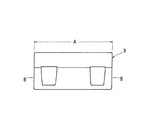
この直動案内ユニットは,特に,無限循環路40における負荷路13の出入口部39に位置するケーシング3の端部の軌道溝7に形成されたクラウニング部9及びR面取り部10に特徴を有しているものである。図2及び図3には,クラウニング部9が形成されるスライダ1を構成するケーシング3が図示されており,図4には,軌道レール2に対して配置されたケーシング3によって形成された軌道溝部分即ち負荷路13の領域を示し,ケーシング3の端部にはクラウニング部9とR面取り部10とが形成された状態を拡大して示している。また,図2で示すリターン路15は,ケーシング3に形成された挿入孔41に挿入された潤滑供給スリーブ16によって形成されている。更に,図5は,図4に示した転動体であるボール5がケーシング3の軌道溝7と接触する接触位置S1,S2と軌道レール2の軌道溝6と接触する接触位置S3,S4とを結ぶ接触角方向の断面,即ち,垂直断面であるA1−A1断面,又はA2−A2断面の一部であるケーシング3の端部とエンドキャップ4を形成するスペーサ11とを示している。
This linear motion guide unit is particularly characterized by the crowning
この直動案内ユニットは,概して,長手方向に沿って軌道面を含む軌道溝6が形成された軌道軸を含む軌道レール2,及び軌道レール2に対して複数のボールでなる転動体5を介して相対摺動するスライダ1から構成されている。スライダ1は,具体的には,軌道溝7及びリターン路15が形成されたケーシング3,ケーシング3の両端に配設され且つ軌道溝7とリターン路15とを連通する方向転換路12が形成されたエンドキャップ4,エンドキャップ4の端面に取り付けられたエンドシール36,及び転動体5を保持する保持バンド37を有している。エンドシール36の端面にはグリースニップル14が配設されている。スライダ1を構成するケーシング3は,軌道レール2の軌道溝6に対向して転動体5と共に負荷を受ける負荷路13を形成する軌道溝7,及び無負荷路でなるリターン路15を有し,また,スライダ1を構成するエンドキャップ4は,負荷路13に続き転動体5が循環する無負荷路40でなる方向転換路12を有する。この直動案内ユニットでは,無限循環路40は,ケーシング3に形成された軌道溝7で構成される軌道路部38,エンドキャップ4に形成された方向転換路12及びケーシング3に形成されたリターン路15から構成されている。また,ケーシング3には,その端面8にエンドキャップ4を位置決めするための位置決め用穴18,及びエンドキャップ4をケーシング3に固定するためのねじ20が螺入する取付け用ねじ穴17が形成されている。
The linear motion guide unit generally includes a
この直動案内ユニットは,特に,負荷路13の出入口部39であるスライダ1の軌道溝7には,転動体5が負荷路13の軌道路部38に滑らかに出入り可能に方向転換路12に向かって緩やかに変化する曲面形状のクラウニング部9が形成されており,更に,スライダ1の軌道溝7の両端部は,曲面形状のR面取り部10がそれぞれ形成されており,クラウニング部9とR面取り部10との境界47は連続的に角部無しの曲面形状で繋がっていることを特徴とする。また,この直動案内ユニットでは,クラウニング部9は,ケーシング3の端面8から軌道溝7の軌道路部38まで,即ち,ケーシング3の端面8からクラウニング部9が形成され始めた軌道溝7までのクラウニング長さLを転動体5の2個分の長さに形成されている。更に,軌道溝7にクラウニング部9が形成される始点45からクラウニング部9の延長線とケーシング3の端面8との交点48までのクラウニング深さHは,基本静定格荷重の半分の荷重を負荷した場合に転動体5によって負荷路13の軌道溝6,7に弾性変形が生じる弾性変形量相当量になるように形成されている。
In particular, the linear motion guide unit is provided in the direction change
また,この直動案内ユニットでは,ケーシング3の軌道溝7は,クラウニング部9と軌道路部38とが同時研削加工されて,クラウニング部9と軌道路部38との表面が同一表面状態に形成され,クラウニング部9の始点45領域での角部が存在していない。クラウニング部9の曲面は,転動体5との接触角方向の断面で見て単一な曲率半径からなる形状に形成されてなる。クラウニング部9は,ケーシング3の長さの20%〜40%に形成することが好ましい。更に,軌道溝7のR面取り部10は,超精密に研磨加工により,曲面形状に形成され,軌道溝7の表面粗さと同等以上の鏡面に形成されてなる。軌道溝7のR面取り部10は,少なくとも垂直断面の曲率半径Rが0.1mm以上の曲面形状に形成されている。また,ケーシング3の軌道溝7は,図4に示すように,軌道レール2の軌道溝6と共に,転動体5と4点(S1,S2,S3,S4)で接触するゴシックアーチ溝形状に形成されている。
In this linear motion guide unit, the
図6〜図9には,スライダ1を構成するエンドキャップ4が示されており,エンドキャップ4はケーシング3の両端面8にそれぞれ配設され(図1),無限循環路40を構成する方向転換路12を備えている。図6と図7には,エンドキャップ4を構成するスペーサ11が図示されており,図8と図9には,エンドキャップ4を構成するエンドキャップ本体30が図示されている。即ち,エンドキャップ4は,エンドキャップ本体30と,エンドキャップ本体30に対向して固定されるスペーサ11とから構成されている。スペーサ11の連結部23は,エンドキャップ本体30に形成された収容凹部32に嵌入し,また,スペーサ11のスペーサ部24は,エンドキャップ本体30に形成された嵌合凹部33に嵌入し,それによってスペーサ11がエンドキャップ本体30に位置決めして取り付けられる。エンドキャップ4の方向転換路12は,スペーサ11に設けた方向転換路12の内周部27と,エンドキャップ本体30に設けた一対の方向転換路12の外周部31とを整合することによってそれぞれ形成される。スペーサ11は,方向転換路12の内周部27を構成する一対のスペーサ部24,及び小さな構成部材であるスペーサ部24をエンドキャップ本体30に一度に組み立て易くするために,それぞれのスペーサ部24を連結する連結部23から構成されている。また,スペーサ部24には,位置決め凸部28及び油孔25が設けられている。スペーサ部24の位置決め凸部28は,ケーシング3に形成した位置決め用穴18に嵌合してエンドキャップ4をケーシング3に位置決め設定される。また,エンドキャップ本体30には,グリースニップル14を取り付けるためのねじ穴34,ねじ穴34に通じる油孔50及び油孔50に通じる油溝51が形成されている。グリースニップル14を通じて供給される潤滑剤は,油孔50,油溝51及び油孔25を通って転動体5へ供給される。
6 to 9 show the
スペーサ11におけるスペーサ部24のリターン路15側の部分には,ケーシング3に形成された挿入孔41の入口部即ち端部に嵌入して転動体5の循環を滑らかに接続する半円筒状の接続管部26が形成されている。また,図8と図9に示されるエンドキャップ本体30の嵌合凹部33には,スペーサ11のスペーサ部24が嵌合して両者が合体でき,内周部27と外周部31とで方向転換路12が完成する。また,方向転換路12の外周部31のリターン路15側の部分には,ケーシング3の挿入孔41の入口部即ち端部に嵌入して転動体5の循環を滑らかに接続する半円筒状の接続管部35が形成され,接続管部35はスペーサ11の接続管部26と整合して円筒状の接続管42に構成される。また,方向転換路12における外周部31の軌道路部38側即ち負荷路13側の部分には,負荷路13から方向転換路12,又は,方向転換路12から負荷路13への転動体5の循環を滑らかに接続するようにすくい爪29が形成され,すくい爪29は,軌道レール2の軌道溝6に摺動可能に嵌入し,その先端部は軌道レール2に形成されている保持バンド37用の挿通溝19に摺動可能に嵌入する状態に配置されている。
A semi-cylindrical connection that smoothly fits in the circulation of the rolling
この直動案内ユニットは,上記したように,負荷路13の端部になるスライダ1におけるケーシング3の軌道溝7の出入口部39には,クラウニング部9及びクラウニング部9の出入口部であるクラウニング部9の端部にR面取り部10が形成されていることを特徴とし,クラウニング部9は,緩やかな曲面形状に形成され,図4に示すように,軌道溝7の出入口部39の全体になるほぼ半周円にわって曲面形状に形成されている。更に,図5に示すクラウニング長さLは,転動体5の2個分の長さに形成されている。また,図5に示すクラウニング深さHは,この直動案内ユニットにおける基本静定格荷重の半分の荷重を負荷した場合に,転動体5によって負荷路13の軌道溝6,7に弾性変形が生じる弾性変形量相当量に形成されている。ここで,基本静定格荷重とは,使用に支障がないように,この直動案内ユニットに予め決められた最大に負荷可能な静的荷重による負荷容量をいう。また,上記弾性変形量相当量は,負荷路13において,転動体5と軌道溝間6,7との間に,弾性変形が軌道溝6,7に生じる接触角方向の弾性変形量に相当する値であり,転動体5と接触して生じる接触角方向における軌道レール2の軌道溝6の弾性変形量とケーシング3の軌道溝7の弾性変形量とを合計した値に成っている。例えば,転動体5であるボールの直径が4.7625mmである直動案内ユニットでは,クラウニング長さLが9.53mmであり,また,クラウニング深さHが0.025mmになる。このようにクラウニング部9は,ケーシング3の軌道溝7における極小部分になっているが,図5では,クラウニング部9を見易くするため,誇張して図示されている。
As described above, the linear motion guide unit includes a
この直動案内ユニットでは,クラウニング深さHは,ケーシング3自体に比較して小さいものであるので,エンドキャップ4のスペーサ部24の内周部27との接続位置Fは,スペーサ部24の位置許容差として±0.05mm程度に設定されるため,クラウニング深さHよりも深くなり(F>H),そこに段差49が形成されることになる。そこで,従来の直動案内ユニットでは,図14に示すように,負荷路13と方向転換路12との接続部には面取り部44が施されていた。この発明による直動案内ユニットは,その接続部になる負荷路13の端面即ちケーシング3の端面8からクラウニング部9へは,角部無しで連続的に繋がる曲面形状になるR面取り部10に形成されているものである。この直動案内ユニットでは,R面取り部10を形成するために,超精密仕上げ研磨テープを使用する専用機で曲面を超精密で研磨加工し,R面取り部10が軌道溝7の表面粗さと同等以上の鏡面に形成されている。また,R面取り部10は,クラウニング部9と同様に,極小な部分になるが,R面取り部10は,ケーシング3の角部に対して少なくとも垂直断面の曲率半径Rが0.1mm以上の曲面形状に形成されている。この実施例では,クラウニング部9とR面取り部10とは,図10に示すように,所定の数値を持つデータに形成されている。図10では,横軸にクラウニング長さLを,縦軸にクラウニング深さHが示されている。
In this linear motion guide unit, the crowning depth H is smaller than that of the
この直動案内ユニットにおけるクラウニング部9は,実質的な負荷を受ける軌道路部38である軌道溝7とクラウニング部9との境界部即ち始点45においても,角部無しで連続的に繋がる曲面形状に形成されている。このことは,ケーシング3の研削加工において,クリープフィード研削方法により軌道溝7からクラウニング部9を同時研削加工しており,それによって軌道路部38とクラウニング部9とは境界の表面において同一曲面状態に形成され,明示的には,軌道路部38とクラウニング部9とが同一表面状態に形成されている。また,クラウニング部9の断面形状は,クリープフィード研削方法により軌道溝7からクラウニング部9を同時研削加工するためにも加工が容易な単一曲面,即ち,単一の曲率半径からなる曲面形状に形成されている。更に,クラウニング部9の役割は,無限循環路40を循環する転動体5が負荷路13である軌道路部38に出入する際に,軌道路部38において負荷された転動体5の数が変化することによって,転動体5によるスライダ1にピッチング,ヨーイング及びローリングの3方向への姿勢変化が生じることになる。そこで,この直動案内ユニットでは,クラウニング部9のクラウニング長さLが転動体5の2個分に設定し且つクラウニング深さHが基本静定格荷重の半分の荷重を負荷した場合に転動体5によって負荷路13の軌道溝6,7に弾性変形が生じる弾性変形量相当量に設定し,それによって,スライダ1の姿勢変化を小さくし,スライダ1の走行精度を高めるものになっている。
The crowning
更に,この直動案内ユニットでは,クラウニング部9は,軌道路部38へ転動体5を滑らかに案内するものになっているので,応力集中も緩和され,耐久性も高いものになり,また,転動体5の転がりも滑らかになるので,スライダ1の摺動抵抗の変動も小さなものになっている。それ故に,クラウニング部9をできるだけ緩やかな曲面形状に形成すれば,上記の転動体5の走行精度が向上することになる。しかしながら,クラウニング部9を緩やかにすればする程,クラウニング長さLは長くなり,限られたスライダ1の負荷路13の長さ,即ち,限られたケーシング長さAからすると,実質の軌道路部38の長さが短くなってしまう。そうすると,スライダ1の所定の定格容量が小さくなってしまい,負荷荷重が小さい軽荷重の使用条件であれば良いが,一般的な仕様に使用できなくなってしまう。
Furthermore, in this linear motion guide unit, the
この直動案内ユニットは,上記のことを考慮して,スライダ1が一般的な仕様の広い範囲に使用可能であり,高精度で,高耐久性のあるものにクラウニング部9を構成するため,クラウニング部9の構成は,ケーシング3の端面8から軌道溝7の軌道路部38までのクラウニング長さLを転動体5の2個分の長さに形成し,且つ軌道溝5の軌道路部38即ち始点45からクラウニング部9の延長線がケーシング3の端面8と交わる交点48までのクラウニング深さHを基本静定格荷重(Coで表す)の半分の荷重(0.5Co)を負荷した場合に転動体5によって負荷路13の軌道溝6,7に弾性変形が生じる弾性変形量相当量に形成したものになっている。即ち,転動体5であるボールの直径が4.7625mmである直動案内ユニットでは,クラウニング長さLが9.53mmであり,クラウニング深さHが0.025mmになっている。このようにクラウニング部9は,目視できない極小部分になって,緩やかな曲面形状に形成されている。
In consideration of the above, the linear motion guide unit can be used in a wide range of general specifications, and the
クラウニング長さLは,今までの試行から導き出されたものになっており,例えば,図12に示すような状態で,軌道レール2に跨架して摺動するスライダ1の走行精度を測定すると,図13に示す各クラウニング仕様での測定結果になっている。図12には,軌道レール2に一つのスライダ1が摺動自在に跨架した状態の直動案内ユニットが示されており,スライダ1の中心から斜め方向に腕を出してスライダ1の姿勢変化を拡大して測定するものであり,その腕の先端位置,即ち,軌道レール2の軸方向中心から150mm離れ,スライダ1中心から軌道レール2の長手方向に200mm離れた位置で,先端の垂直方向及び水平方向の変化を測定するものになっている。図13は,図12に示す直動案内ユニットで測定した結果の一例を示しており,クラウニング深さLが転動体5の2個分の長さに形成されたスライダ1の姿勢変化,即ち,先端の垂直方向及び水平方向の変化を符号J1で示している。また,クラウニング深さLが転動体の1.5個分の長さに形成されたスライダの姿勢変化,即ち,先端の垂直方向及び水平方向の変化を符号J2で示している。更に,面取り部10の状態,即ち,緩やかな傾斜に無く,例えば,クラウニング深さHが大きい状態で,クラウニング部9が形成されていないスライダ1の姿勢変化,即ち,先端の垂直方向及び水平方向の変化を符号J3で示している。また,符号J1及び符号J2でのクラウニング深さHは,上記0.5Co相当分に形成されたものになっている。また,図13において,縦軸は変位(μm)を示し,また,横軸はストローク(mm)を示している。
The crowning length L is derived from previous trials. For example, when the traveling accuracy of the
上記の測定結果から分かるように,クラウニング部9のクラウニング長さLは,転動体5の1.5個分の長さにしたもの(J2)でも走行精度が改善されるが,転動体5の2個分の長さでなるもの(J1)は一層改善されている。即ち,クラウニング部9のクラウニング長さLが2個分の(J1)では,垂直方向及び水平方向の両方とも変位が小さく走行精度が極めて良好であることが分かる。これに対して,軌道溝7のクラウニングが施されていないもの(J3)では,水平方向の変位が大きくなり,走行精度が悪化することが分かる。また,図示しないが,転動体5の3個分の長さでなるものは,更に一層改善される。しかし,クラウニング長さLを転動体5の3個分の長さにすると,直動案内ユニットの定格の負荷容量が小さくなってしまう。勿論,ケーシング長さAが通常よりも長いもの,即ち,スライダ1の軌道溝7の長さが長いものでは影響が小さいものになるので,利用できることは勿論である。ここで,クラウニング部9のクラウニング長さLを,転動体5の2個分の長さにすれば,直動案内ユニットの定格の負荷容量への影響も小さく,或いは影響が無く,転動体5の走行精度が最良になっており,課題を解決する直動案内ユニットを提供できることになる。この発明による直動案内ユニットでは,クラウニング部9のクラウニング長さLを,転動体5の2個分の長さとは,クラウニング長さLが,転動体5の
1.5個<L<2.5個分の範囲を許容範囲として含むものである。また,ケーシング長さAが通常よりも長いものは,転動体の3個分の長さでもよいことは勿論である。また,ケーシング長さAは,クラウニング部9がケーシング3の長さAの20%〜40%に形成されて好適であり,クラウニング長さLが2Da(Daは転動体の径)になるので,逆算して求められる。
As can be seen from the above measurement results, the crowning length L of the
また,ケーシング3に対するクラウニング深さHは,クラウニング部9が緩やかな程好ましいものであるが,一般的な仕様の広い範囲に使用可能にするために,クラウニング深さHを基本静定格荷重(Co)の半分の荷重(0.5Co)を負荷した場合に,転動体5によって負荷路13の軌道溝6,7に弾性変形が生じる弾性変形量相当量に形成されたものになっており,しかも,クラウニング長さLを転動体5の2個分の長さに形成することで最適なものにしている。特に,この直動案内ユニットは,ケーシング3の端面8とクラウニング部9との接続部分を角部無しで連続的に繁がる曲面形状になるR面取り部10に形成したことにある。接続部分であるR面取り部10は,図11に示すように,負荷路13と方向転換路12との接続部になっており,図5に示すように,エンドキャップ4の方向転換路12の内周部27の位置(深さF)よりも突出する状態になっている。この直動案内ユニットは,上記のように構成することによって,無限循環路40を循環する転動体5(a)〜5(f),図11では転動体5(d)に相当するものが接続部であるR面取り部10に衝突することになる。従来の直動案内ユニットにおいて,転動体5が高速に循環するものでは,衝撃力が大きいものになり,この接続部が損傷し早期寿命になっていた。そこで,この直動案内ユニットでは,R面取り部10は,クラウニング部9へ角部無しで連続的に繋がる曲面形状にして,超精密に研磨加工により軌道溝7の表面祖さと同等以上の鏡面に形成することによって,転動体5の衝撃力が緩和され,高速の使用状況においても,定格寿命を充分に満足するものになっている。R面取り部10は,図14に示す従来のように角部46が残るものでは0.1mmより小さな損傷度になっているので,少なくとも垂直断面の曲率半径Rが0.1mm以上の曲面形状に形成されればよいものである。
In addition, the crowning depth H with respect to the
この直動案内ユニットでは,クラウニング部9は,特に,軌道溝7は,軌道レール2の軌道溝6と共に,転動体5と4点(図4でS1,S2,S3,S4で示す)接触するゴシックアーチ溝形状でなる直動案内ユニットに適用して効果があるものになっている。ゴシックアーチ溝でなる4点接触形式の軌道溝7は,図4に示すように,一つの負荷路13にあって,上軌道溝21と下軌道溝22との2つの軌道溝が合体した軌道溝7に構成されたものである。軌道溝7がゴシックアーチ溝に形成されると,例えば,転動体5は,方向転換路12から2つの上軌道溝21と下軌道溝22に同時に侵入する形態になり,出入口部39の影響が大きなものになっている。従って,この直動案内ユニットは,上記のようなクラウニング部9を形成することにより,効果が著しいものになっている。また,この直動案内ユニットは,軌道溝7の極小な部分にもかかわらず,効果があり,より簡単に形成できる負荷路13の出入口部39のクラウニング形状を提供するものであり,それによって,高精度で高寿命な直動案内ユニットを提供することができる。
In this linear motion guide unit, the crowning
この直動案内ユニットは,工作機械,半導体製造装置,精密測定装置等の相対摺動部材を備えた各種装置に使用され,近年に要望される高精度として高走行精度,高速・高加減速における高耐久性に対応できるものである。 This linear motion guide unit is used in various devices with relative sliding members such as machine tools, semiconductor manufacturing equipment, precision measuring equipment, etc., and has been required in recent years for high precision, high running precision, high speed, high acceleration / deceleration. It can cope with high durability.
1 スライダ
2 軌道レール
3 ケーシング
4 エンドキャップ
5 転動体
6 軌道溝(軌道レール)
7 軌道溝(ケーシング)
8 端面(ケーシング)
9 クラウニング部
10 R面取り部
11 スペーサ(エンドキャップ)
12 方向転換路
13 負荷路
14 グリースニップル
15 リターン路
16 潤滑供給スリーブ(リターン路嵌合)
24 スペーサ部(スペーサ)
30 エンドキャップ本体
38 軌道路部(負荷路の)
39 出入口部(負荷路の)
45 始点
47 境界
48 交点
A ケーシング長さ
H クラウニング深さ
L クラウニング長さ
DESCRIPTION OF
7 Track groove (casing)
8 End face (casing)
9 Crowning part 10 R chamfered
12
24 Spacer (Spacer)
30
39 Entrance / exit (load path)
45
Claims (1)
前記ケーシングの前記軌道溝は,前記軌道レールの前記軌道溝と共に前記ボールと4点接触しているゴシックアーチ溝形状に形成されており,
前記負荷路の出入口部を構成する前記ケーシングの前記軌道溝の両端部には,前記ボールが前記負荷路に出入り可能になる前記方向転換路に向かってクラウニング部が形成されていることから成る直動案内ユニットにおいて,
前記クラウニング部は,前記スライダの走行精度を高めるために,クリープフィード研削方法により前記軌道溝と同時研削加工され前記軌道溝と角部無しで連続して繋がり前記軌道溝の前記出入口部の全体になる略半円周にわたって曲面形状に形成され,前記ボールと前記ケーシングの前記軌道溝とが接触する2ヶ所のそれぞれ接触角方向の断面において,単一の曲率半径から成る前記曲面形状に形成されており,
前記ケーシングの前記長手方向に沿って前記ケーシングの前記端面から前記曲面形状の始点までのクラウニング長さは,前記ボールの直径の実質的に2倍の長さに形成され,前記軌道溝の前記両端部の前記クラウニング長さを合計した長さが前記ケーシングの全長に対して20%〜40%に形成されており,
前記接触角方向に沿って前記曲面形状の前記始点から前記曲面形状と前記ケーシングの前記端面との交点までのクラウニング深さは,前記直動案内ユニットの基本静定格荷重の半分の荷重を負荷したときに前記負荷路における前記ボールと前記軌道溝間との間に,弾性変形が前記軌道溝に生じる前記接触角方向の弾性変形量に相当する値に形成されており,
更に,それぞれの前記クラウニング部の前記ケーシングの前記端面側は,前記クラウニングと前記ケーシングの前記端面との接続部分が前記方向転換路の前記内周部の端になる前記スペーサ部の端へ接続する曲面形状のR面取り部に形成され,且つ前記クラウニング部の前記曲面形状と前記R面取り部の前記曲面形状との境界部は連続して角部無しで繋がっている曲面形状に形成されており,
各々の前記R面取り部は,前記方向転換路から前記ゴシックアーチ溝形状になる前記軌道溝の上軌道溝の前記クラウニング部と下軌道溝の前記クラウニング部とに侵入する前記ボールの衝撃力を緩和するために超精密仕上げ研摩テープを使用して超精密に研摩加工された表面粗さが前記ケーシングの前記軌道溝の表面粗さと同等以上の鏡面に形成されていることを特徴とする直動案内ユニット。 A track rail formed with a track groove along a longitudinal direction, and a slider that slides relative to the track rail via a ball that is a plurality of rolling elements, wherein the slider includes the track groove of the track rail. And a load path formed between the track grooves and a return path formed in parallel to the load path, and the load path and the return path respectively disposed on both end surfaces of the casing. And an end cap formed with a direction change path communicating with the ball, and the ball circulating through an infinite circulation path composed of the load path, the return path, and a pair of the direction change paths. A space having an end cap body that forms an outer peripheral portion of the direction changing path, and a spacer portion that is fixed to the end cap body and forms an inner peripheral portion of the direction changing path. It is composed of a,
The raceway groove of the casing is formed into a Gothic arch groove shape that is in contact with the ball at four points together with the raceway groove of the raceway rail,
A crowning portion is formed at both end portions of the raceway groove of the casing constituting the entrance / exit portion of the load path toward the direction changing path where the balls can enter and exit the load path. In the motion guide unit,
The crowning portion is ground simultaneously with the raceway groove by a creep feed grinding method in order to increase the running accuracy of the slider, and is continuously connected to the raceway groove without a corner portion. becomes formed over substantially half the circumference in a curved shape, Te respectively contact angle direction section smell two places of said raceway grooves of the said ball casing is in contact, it is formed in the curved surface shape consisting of a single radius of curvature And
The crowning length from the end surface of the casing to the start point of the curved shape along the longitudinal direction of the casing is formed to be substantially twice the diameter of the ball , and the both ends of the track groove The total length of the crowning length of the portion is formed to be 20% to 40% with respect to the total length of the casing ,
The crowning depth from the start point of the curved surface shape to the intersection of the curved surface shape and the end surface of the casing along the contact angle direction was loaded with half the basic static load rating of the linear motion guide unit. Sometimes, between the ball and the raceway groove in the load path, elastic deformation is formed to a value corresponding to the amount of elastic deformation in the contact angle direction that occurs in the raceway groove,
Furthermore, the end surface side of the casing of each of the crowning portions is connected to an end of the spacer portion where a connection portion between the crowning and the end surface of the casing is an end of the inner peripheral portion of the direction change path. that is formed on the R-chamfered portion of the song-sectional shape, and a boundary portion between the curved surface shape of the curved surface shape and the R-chamfered portion of the crowning portion is formed in a curved shape which is connected without corners in succession And
Each of the R chamfered portions alleviates the impact force of the ball that enters the crowning portion of the upper raceway groove and the crowning portion of the lower raceway groove that are formed in the Gothic arch groove shape from the direction change path. Therefore, the linear motion guide unit is characterized in that the surface roughness polished with the ultra-precision finishing polishing tape is formed into a mirror surface equal to or greater than the surface roughness of the raceway groove of the casing. .
Priority Applications (4)
| Application Number | Priority Date | Filing Date | Title |
|---|---|---|---|
| JP2004087471A JP4565545B2 (en) | 2004-03-24 | 2004-03-24 | Linear motion guidance unit |
| DE602005014896T DE602005014896D1 (en) | 2004-03-24 | 2005-03-17 | Linear guide unit |
| EP05251618A EP1580447B1 (en) | 2004-03-24 | 2005-03-17 | Linear motion guide unit |
| US11/086,910 US7677804B2 (en) | 2004-03-24 | 2005-03-23 | Linear motion guide unit |
Applications Claiming Priority (1)
| Application Number | Priority Date | Filing Date | Title |
|---|---|---|---|
| JP2004087471A JP4565545B2 (en) | 2004-03-24 | 2004-03-24 | Linear motion guidance unit |
Publications (2)
| Publication Number | Publication Date |
|---|---|
| JP2005273765A JP2005273765A (en) | 2005-10-06 |
| JP4565545B2 true JP4565545B2 (en) | 2010-10-20 |
Family
ID=34858441
Family Applications (1)
| Application Number | Title | Priority Date | Filing Date |
|---|---|---|---|
| JP2004087471A Expired - Lifetime JP4565545B2 (en) | 2004-03-24 | 2004-03-24 | Linear motion guidance unit |
Country Status (4)
| Country | Link |
|---|---|
| US (1) | US7677804B2 (en) |
| EP (1) | EP1580447B1 (en) |
| JP (1) | JP4565545B2 (en) |
| DE (1) | DE602005014896D1 (en) |
Families Citing this family (16)
| Publication number | Priority date | Publication date | Assignee | Title |
|---|---|---|---|---|
| DE102005036660A1 (en) * | 2005-08-04 | 2007-02-08 | Schaeffler Kg | wheel bearing unit |
| US7988360B2 (en) * | 2005-11-01 | 2011-08-02 | Thk Co., Ltd. | Motion guide device |
| JP4853254B2 (en) | 2006-11-27 | 2012-01-11 | 日本精工株式会社 | Linear motion guide device |
| JP5103057B2 (en) | 2007-05-25 | 2012-12-19 | 日本トムソン株式会社 | Roller type linear motion guide unit |
| US8136998B2 (en) * | 2007-12-13 | 2012-03-20 | Jtekt Corporation | Bearing apparatus |
| US8882352B2 (en) * | 2011-11-04 | 2014-11-11 | Thk Co., Ltd. | Motion guide device |
| JP5724894B2 (en) * | 2012-01-31 | 2015-05-27 | 日本精工株式会社 | Linear guide device |
| JP6323127B2 (en) * | 2014-04-01 | 2018-05-16 | 日本精工株式会社 | Linear motion guide device |
| JP5932926B2 (en) * | 2014-09-19 | 2016-06-08 | Thk株式会社 | Motion guide device, actuator |
| CN105570295A (en) * | 2016-02-01 | 2016-05-11 | 嘉兴海菱达精密传动科技有限公司 | Rolling linear guide rail pair |
| CN105570296A (en) * | 2016-02-01 | 2016-05-11 | 嘉兴海菱达精密传动科技有限公司 | Improved rolling linear guide rail pair |
| JP6945980B2 (en) * | 2016-08-31 | 2021-10-06 | 日本トムソン株式会社 | How to load the rolling element into the bending rolling guide unit and its slider |
| JP6981746B2 (en) | 2016-10-26 | 2021-12-17 | 日本トムソン株式会社 | Linear guidance unit |
| JP6827843B2 (en) | 2017-02-23 | 2021-02-10 | 日本トムソン株式会社 | Linear guidance unit |
| WO2019044493A1 (en) * | 2017-08-29 | 2019-03-07 | Thk株式会社 | Motion guiding device |
| JP7495865B2 (en) * | 2020-10-28 | 2024-06-05 | 日本トムソン株式会社 | Linear guide unit |
Family Cites Families (15)
| Publication number | Priority date | Publication date | Assignee | Title |
|---|---|---|---|---|
| JPS58169221U (en) * | 1982-05-07 | 1983-11-11 | 日本精工株式会社 | track guide bearing |
| JPS59208218A (en) * | 1983-05-11 | 1984-11-26 | Hiroshi Teramachi | Revolving bearing |
| JPH0654129B2 (en) * | 1983-12-29 | 1994-07-20 | 日本トムソン 株式会社 | Linear motion rolling bearing |
| JPH0235051Y2 (en) * | 1985-02-14 | 1990-09-21 | ||
| US5649770A (en) * | 1996-04-04 | 1997-07-22 | Hiwin Technologies Corp. | Ball circulating structure for linear guide assembly |
| US5909965A (en) * | 1997-09-12 | 1999-06-08 | Hiwin Technologies Corp. | Recirculation path unit for linear rolling bearings |
| JP2000120674A (en) * | 1998-10-12 | 2000-04-25 | Nsk Ltd | Linear motion guide device |
| JP2001173718A (en) * | 1999-12-20 | 2001-06-26 | Thk Co Ltd | Heavy load plane guiding device for base isolation |
| JP4051845B2 (en) * | 2000-01-13 | 2008-02-27 | 日本精工株式会社 | Linear motion guide bearing device |
| JP3420204B2 (en) | 2000-11-17 | 2003-06-23 | Thk株式会社 | Guidance device |
| TW471577U (en) * | 2001-04-20 | 2002-01-01 | Hiwin Tech Corp | Improved structure for ball spacer of linear transmission device |
| JP4540893B2 (en) | 2001-07-23 | 2010-09-08 | 日本精工株式会社 | Method for designing rolling linear motion guide device and rolling linear motion guide device designed thereby |
| JP4423851B2 (en) * | 2002-02-28 | 2010-03-03 | 日本精工株式会社 | Method for manufacturing linear motion guide device |
| DE112004001048B4 (en) * | 2003-08-25 | 2014-08-28 | Nsk Ltd. | Linear motion guide device |
| WO2005108807A1 (en) * | 2004-05-12 | 2005-11-17 | Thk Co., Ltd. | Rolling machine element |
-
2004
- 2004-03-24 JP JP2004087471A patent/JP4565545B2/en not_active Expired - Lifetime
-
2005
- 2005-03-17 DE DE602005014896T patent/DE602005014896D1/en active Active
- 2005-03-17 EP EP05251618A patent/EP1580447B1/en active Active
- 2005-03-23 US US11/086,910 patent/US7677804B2/en active Active
Also Published As
| Publication number | Publication date |
|---|---|
| DE602005014896D1 (en) | 2009-07-30 |
| EP1580447A2 (en) | 2005-09-28 |
| JP2005273765A (en) | 2005-10-06 |
| EP1580447B1 (en) | 2009-06-17 |
| US7677804B2 (en) | 2010-03-16 |
| EP1580447A3 (en) | 2007-11-14 |
| US20050213856A1 (en) | 2005-09-29 |
Similar Documents
| Publication | Publication Date | Title |
|---|---|---|
| JP4565545B2 (en) | Linear motion guidance unit | |
| US7159481B2 (en) | Ball screw device and linear motion device | |
| JP3950511B2 (en) | Linear motion rolling guide unit | |
| JP4278686B2 (en) | Rolling guide device | |
| JP7194794B2 (en) | Linear guide unit | |
| JP5103057B2 (en) | Roller type linear motion guide unit | |
| JP4853254B2 (en) | Linear motion guide device | |
| TW201405023A (en) | Single-axis actuator | |
| JP4071975B2 (en) | Linear motion guidance unit | |
| JP4423851B2 (en) | Method for manufacturing linear motion guide device | |
| JP2005069343A (en) | Guide unit | |
| US10294991B2 (en) | Linear motion guide unit | |
| JP2003278752A (en) | Direct action guide unit interposing separator between roller | |
| JP2006144840A (en) | Linear guide unit | |
| JP2000046052A (en) | Linear motion guide device | |
| JP4634223B2 (en) | Linear motion guidance unit | |
| US5490729A (en) | Ball spline | |
| JP2005214424A (en) | Ball screw mechanism and linear drive actuator | |
| JP2001124075A (en) | Linear motion rolling guide unit | |
| JP2007003011A (en) | Linear guide device | |
| JP2015048876A (en) | Positioning mechanism, guide device and positioning method | |
| JP2005042795A (en) | Linear motion guiding bearing device | |
| JP2005098355A (en) | Linear motion guide device | |
| JP2006329433A (en) | Ball screw device and linear motion device |
Legal Events
| Date | Code | Title | Description |
|---|---|---|---|
| A621 | Written request for application examination |
Free format text: JAPANESE INTERMEDIATE CODE: A621 Effective date: 20061207 |
|
| A977 | Report on retrieval |
Free format text: JAPANESE INTERMEDIATE CODE: A971007 Effective date: 20090319 |
|
| A131 | Notification of reasons for refusal |
Free format text: JAPANESE INTERMEDIATE CODE: A131 Effective date: 20090407 |
|
| A521 | Request for written amendment filed |
Free format text: JAPANESE INTERMEDIATE CODE: A523 Effective date: 20090601 |
|
| A02 | Decision of refusal |
Free format text: JAPANESE INTERMEDIATE CODE: A02 Effective date: 20090630 |
|
| A521 | Request for written amendment filed |
Free format text: JAPANESE INTERMEDIATE CODE: A523 Effective date: 20090924 |
|
| A911 | Transfer to examiner for re-examination before appeal (zenchi) |
Free format text: JAPANESE INTERMEDIATE CODE: A911 Effective date: 20091007 |
|
| A912 | Re-examination (zenchi) completed and case transferred to appeal board |
Free format text: JAPANESE INTERMEDIATE CODE: A912 Effective date: 20091030 |
|
| A01 | Written decision to grant a patent or to grant a registration (utility model) |
Free format text: JAPANESE INTERMEDIATE CODE: A01 |
|
| A61 | First payment of annual fees (during grant procedure) |
Free format text: JAPANESE INTERMEDIATE CODE: A61 Effective date: 20100730 |
|
| R150 | Certificate of patent or registration of utility model |
Ref document number: 4565545 Country of ref document: JP Free format text: JAPANESE INTERMEDIATE CODE: R150 Free format text: JAPANESE INTERMEDIATE CODE: R150 |
|
| FPAY | Renewal fee payment (event date is renewal date of database) |
Free format text: PAYMENT UNTIL: 20130813 Year of fee payment: 3 |
|
| R250 | Receipt of annual fees |
Free format text: JAPANESE INTERMEDIATE CODE: R250 |
|
| R250 | Receipt of annual fees |
Free format text: JAPANESE INTERMEDIATE CODE: R250 |
|
| R250 | Receipt of annual fees |
Free format text: JAPANESE INTERMEDIATE CODE: R250 |
|
| EXPY | Cancellation because of completion of term |