US5909965A - Recirculation path unit for linear rolling bearings - Google Patents
Recirculation path unit for linear rolling bearings Download PDFInfo
- Publication number
- US5909965A US5909965A US08/928,646 US92864697A US5909965A US 5909965 A US5909965 A US 5909965A US 92864697 A US92864697 A US 92864697A US 5909965 A US5909965 A US 5909965A
- Authority
- US
- United States
- Prior art keywords
- passages
- linear
- recirculation path
- reversing
- curve
- Prior art date
- Legal status (The legal status is an assumption and is not a legal conclusion. Google has not performed a legal analysis and makes no representation as to the accuracy of the status listed.)
- Expired - Lifetime
Links
Images


Classifications
-
- F—MECHANICAL ENGINEERING; LIGHTING; HEATING; WEAPONS; BLASTING
- F16—ENGINEERING ELEMENTS AND UNITS; GENERAL MEASURES FOR PRODUCING AND MAINTAINING EFFECTIVE FUNCTIONING OF MACHINES OR INSTALLATIONS; THERMAL INSULATION IN GENERAL
- F16C—SHAFTS; FLEXIBLE SHAFTS; ELEMENTS OR CRANKSHAFT MECHANISMS; ROTARY BODIES OTHER THAN GEARING ELEMENTS; BEARINGS
- F16C29/00—Bearings for parts moving only linearly
- F16C29/04—Ball or roller bearings
- F16C29/06—Ball or roller bearings in which the rolling bodies circulate partly without carrying load
- F16C29/0633—Ball or roller bearings in which the rolling bodies circulate partly without carrying load with a bearing body defining a U-shaped carriage, i.e. surrounding a guide rail or track on three sides
- F16C29/0635—Ball or roller bearings in which the rolling bodies circulate partly without carrying load with a bearing body defining a U-shaped carriage, i.e. surrounding a guide rail or track on three sides whereby the return paths are provided as bores in a main body of the U-shaped carriage, e.g. the main body of the U-shaped carriage is a single part with end caps provided at each end
- F16C29/0638—Ball or roller bearings in which the rolling bodies circulate partly without carrying load with a bearing body defining a U-shaped carriage, i.e. surrounding a guide rail or track on three sides whereby the return paths are provided as bores in a main body of the U-shaped carriage, e.g. the main body of the U-shaped carriage is a single part with end caps provided at each end with balls
- F16C29/064—Ball or roller bearings in which the rolling bodies circulate partly without carrying load with a bearing body defining a U-shaped carriage, i.e. surrounding a guide rail or track on three sides whereby the return paths are provided as bores in a main body of the U-shaped carriage, e.g. the main body of the U-shaped carriage is a single part with end caps provided at each end with balls with two rows of balls, one on each side of the rail
-
- F—MECHANICAL ENGINEERING; LIGHTING; HEATING; WEAPONS; BLASTING
- F16—ENGINEERING ELEMENTS AND UNITS; GENERAL MEASURES FOR PRODUCING AND MAINTAINING EFFECTIVE FUNCTIONING OF MACHINES OR INSTALLATIONS; THERMAL INSULATION IN GENERAL
- F16C—SHAFTS; FLEXIBLE SHAFTS; ELEMENTS OR CRANKSHAFT MECHANISMS; ROTARY BODIES OTHER THAN GEARING ELEMENTS; BEARINGS
- F16C29/00—Bearings for parts moving only linearly
- F16C29/04—Ball or roller bearings
- F16C29/06—Ball or roller bearings in which the rolling bodies circulate partly without carrying load
- F16C29/0602—Details of the bearing body or carriage or parts thereof, e.g. methods for manufacturing or assembly
- F16C29/0609—Details of the bearing body or carriage or parts thereof, e.g. methods for manufacturing or assembly of the ends of the bearing body or carriage where the rolling elements change direction, e.g. end caps
-
- F—MECHANICAL ENGINEERING; LIGHTING; HEATING; WEAPONS; BLASTING
- F16—ENGINEERING ELEMENTS AND UNITS; GENERAL MEASURES FOR PRODUCING AND MAINTAINING EFFECTIVE FUNCTIONING OF MACHINES OR INSTALLATIONS; THERMAL INSULATION IN GENERAL
- F16C—SHAFTS; FLEXIBLE SHAFTS; ELEMENTS OR CRANKSHAFT MECHANISMS; ROTARY BODIES OTHER THAN GEARING ELEMENTS; BEARINGS
- F16C29/00—Bearings for parts moving only linearly
- F16C29/04—Ball or roller bearings
- F16C29/06—Ball or roller bearings in which the rolling bodies circulate partly without carrying load
- F16C29/068—Ball or roller bearings in which the rolling bodies circulate partly without carrying load with the bearing body fully encircling the guide rail or track
- F16C29/0683—Ball or roller bearings in which the rolling bodies circulate partly without carrying load with the bearing body fully encircling the guide rail or track the bearing body encircles a rail or rod of circular cross-section, i.e. the linear bearing is not suited to transmit torque
- F16C29/0685—Ball or roller bearings in which the rolling bodies circulate partly without carrying load with the bearing body fully encircling the guide rail or track the bearing body encircles a rail or rod of circular cross-section, i.e. the linear bearing is not suited to transmit torque with balls
- F16C29/0688—Ball or roller bearings in which the rolling bodies circulate partly without carrying load with the bearing body fully encircling the guide rail or track the bearing body encircles a rail or rod of circular cross-section, i.e. the linear bearing is not suited to transmit torque with balls whereby a sleeve surrounds the circulating balls and thicker part of the sleeve form the load bearing tracks
Definitions
- the present invention is a recirculation path unit of a linear rolling bearing.
- the unit includes a linear loading passage, a linear unloading passage, and two directional reversing passages, which are connected to the linear loading and unloading passages, to form a closed recirculation path within which rolling elements perform an infinite motion.
- the methodology of designing the reversing passages of the present invention is based on the continuity of the curvature, which is expected to be able to vary from zero to an assigned value and vice versa, at the connecting points to the loading and unloading linear passages. As a result, not only the continuity of the slope of the tangential lines at the vicinity of the connecting points but also the continuity of the curvature of the whole circulation path can be ensured.
- the continuity of the curvature provided by the present invention eliminates abrupt changes in centrifugal acceleration at the spots where the rolling elements enter or leave the reversing passage, thus reducing the impact force acting on the wall of the directional reversing passage by the element, the sliding function forces and noise induced by the vibration under high-speed operation conditions.
- the design of the conventional reversing passages for the rolling elements in a linear bearing emphasizes the direction reversing function, with the goal of making the curves be tangent to each other at the connecting points, by forming the reversing passages through the connection of straight lines, circular arcs or elliptic arcs in order to cause the slope to be made the same at the connecting points.
- failure to take into account the continuity of a curvature at the connecting point results in an abrupt change in the centrifugal acceleration and a tremendous impact force that acts on the turning wall, inducing sliding function, vibrations, and noise for a rolling element moving with a high speed in the reversing passage.
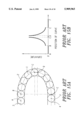
- U.S. Pat. No. 4,296,974 provides an example of such a structure, which is illustrated in FIG. 11A of the present application where a reversing passage 1 consists of a semi circular arc with radius R and the passage is tangent to the other two linear passages in the connecting points.
- a reversing passage 1 consists of a semi circular arc with radius R and the passage is tangent to the other two linear passages in the connecting points.
- the curvature of the passage changes abruptly from zero to 1/R at point B.
- the curvature of the passage changes also abruptly from 1/R to zero at point C.
- a reversing passage design composed of two pieces of one-quarter circular arcs and a piece of straight line segment is disclosed in U.S. Pat. No.
- FIG. 12A which is represented by FIG. 12A of the present application.
- the slopes of these two reversing passages of this design are continuous at the connecting point, the inferior characteristic of the convention design such as the impact force, sliding function, vibration and noise caused by ignorance of the continuity of the curvature at the connection point remain the same. This can be seen through the curvature variation of these cases shown in FIGS. 11B and 12B.
- Linear ball bearings including the linear Guideway, the linear ball bush, and the ball spline are widely used in modem mechanical, semiconductor and automation industries. Because of the demands of high efficiency in manufacturing, the speed requirement of the linear bearing is much higher than the conventional practice. Under this high-speed requirement, the issues of impact, sliding function, and vibration and noise become more and more significant.
- the conventional design of the reversing path of a linear bearing pays attention simply to the continuity of the slopes of tangent lines at a connecting point.
- the reversing circuit is mostly made through the composition of straight lines, circular arcs or elliptical arcs with the same tangent at the connecting points. Though the slopes are continuous, the curvatures are not continuous at the connecting points.
- the radius of the curvature changes rapidly so that it causes the rolling element to turn direction abruptly and a centrifugal acceleration to appear instantaneously. It will also induce extra impact and functional force by the abrupt change in the direction of the rolling element.
- the rolling element will have unfavorable jerking, colliding and jostling when passing through the spot of the connection, and will have a less smooth motion and generate enormous noise resulting in a reduction of the mechanical efficiency.
- the object of the invention is to provide a planar or spatial reversing passage circuit to connect the loading and unloading passages in a recirculation path unit of a linear bearing.
- the specific planar or spatial curves are defined so that the curvature of the curves can be altered continuously from zero to a designated value. Using this characteristic of the curve to connect the reversing passage with the straight loading and unloading passages, elimination of acceleration, reduction of the sliding function and the generating of a smooth reversing motion can be obtained and the high speed and highly efficient linear motion can be achieved.
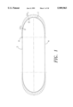
- FIG. 1. is a plot of the curvature in the reversing passage of the present invention.
- FIG. 2A is a plot of the reversing passage composed of a Clothoidal curve.
- FIG. 2B is a plot shows the curvature variation of the curve shown in FIG. 2A.
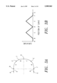
- FIG. 3A is a plot shows the modified Clothoidal curve from FIG. 2A.
- FIG. 3B is a plot shows the curvature variation of the curve shown in FIG. 3A.
- FIG. 4A is a plot shows another modified Clothoidal curve from FIG. 2A.
- FIG. 4B is a plot shows the curvature variation of the curve shown in FIG. 4A.
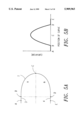
- FIG. 5A is a plot shows another modified Clothoidal curve from FIG. 2A.
- FIG. 5B is a plot shows the curvature variation of the curve shown in FIG. 5A.
- FIG. 6A is a plot shows another modified Clothoidal curve from FIG. 2A.
- FIG. 6B is a plot shows the curvature variation of the curve shown in FIG. 6A.
- FIG. 7 is a plot shows the curve formed by the intersections of two Clothoidal planes.
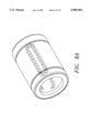
- FIG. 8A is the recirculation path of a linear ball bush.
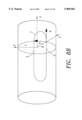
- FIG. 8B is a Clothoidal curve on a cylindrical coordinate system.
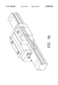
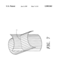
- FIG. 9A is a recirculation path of a rolling ball linear guideway.
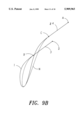
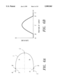
- FIG. 9B is a comparison of the reversing passages between a conventional recirculation path and those of the present design.
- FIG. 9C is a plot shows the curvature variation of the curve shown in FIG. 9B.
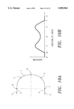
- FIG. 10. is a plot of the reversing path of the present invention formed by a B2zier Curve.
- FIG. 11A is a plot shows a conventional reversing passage composed of a piece of semi circular arc.
- FIG. 11B is a plot shows the curvature variation of the curve shown in FIG. 11A.
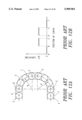
- FIG. 12A is a plot shows a conventional reversing passage composed of two pieces of quarter circular arcs and a piece of straight line segment.
- FIG. 12B is a plot shows the curvature variation of the curve shown in FIG. 12A.
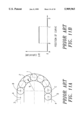
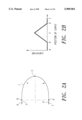
- FIG. 13A is a plot shows a conventional reversing passage composed of three pieces of circular arcs.
- FIG. 13B is a plot shows the curvature variation of the curve shown in FIG. 13A.
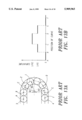
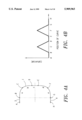
- FIG. 14A is a plot shows a conventional reversing passage composed of five pieces of circular arcs.
- FIG. 14B is a plot shows the curvature variation of the curve shown in FIG. 14A.
- FIG. 15A is a plot shows a conventional reversing passage composed of two pieces of quarter elliptic arcs and a piece of straight line segment.
- FIG. 15B is a plot shows the curvature variation of the curve shown in FIG. 15A.
- FIG. 1 to 10B are the practical application examples of the practical application of the present invention.
- FIG. 11A to 15B are the conventional reversing passages.
- the technique that makes the connected straight lines, circular arcs or elliptic arcs tangent to each other at the connecting point is generally used to form a slope-continuous closed recirculation path so that the smoothness of the motion of a rolling element passing through the reversing passage can be ensured.
- the continuity of the slope at the connecting point can be obtained through this technique, the curvatures in the vicinity of the connecting points are still discontinuously mismatched and will cause a sharp change of the centrifugal acceleration.
- the unfavorable sharp changing of the acceleration can generate a tremendous impact force at the reversing passage, causing sliding function, and reciprocal colliding of the rolling elements that will reduce the mechanical efficiency and produce a tremendous level of noise.
- the present invention introduces an innovative curvature-connecting technique that can be used to ensure the continuity of the slope as well as the curvature of the whole recirculation passage of a linear bearing.
- the centrifugal acceleration of the rolling element in the reversing passage can be made smooth from zero to a certain design value.
- the impact force from the rolling element to the reversing wall will be reduced, and sliding function, the noise induced by vibration, and the noise induced by colliding of the rolling bodes can be eliminated.
- the curvature of a moving path will directly affect the centrifugal force on a body when changing directions.
- the acceleration a n increases abruptly to V 2 /R that it means the acceleration is proportional to the curvature.
- curve 1 is a circular arc and its radius R is a constant, with the result that the acceleration of the rolling element increases abruptly to a certain value at the instance of the rolling element moving into the reversing path from a straight line.
- the direction of the acceleration of the rolling element also changes abruptly and will inevitably cause jerking of the rolling element and induce an impact force against the wall of the reversing passage.
- FIG. 1 shows the reversing passage designed by the connecting technique of the present invention, where the curvature of the passage varies continuously from zero to 1/rp and to 1/r Q when element 2 passes from point A to point P and to point Q, respectively.
- the centrifugal acceleration thus changes smoothly from zero to V 2 /rp and then to V 2 /rQ, respectively. Since the centrifugal acceleration varies continuously, the jerk and collision of the rolling element 2 can be avoided at the conjunction point.
- the linear bearing recirculation design unit of the present invention uses the curvature as the design parameter.
- Clothoidal Curve also called a Cornu curve, or Euler's Curve
- Bezier Curve or other kinds of similar curves having the required curvature properties.
- Clothoidal curve also called a Cornu curve, or Euler's Curve
- Bezier Curve or other kinds of similar curves having the required curvature properties.
- Clothoidal curve The general form of a Clothoidal curve can be expressed as ##EQU2## where (X(u), Y(u)) is a point in the Clothoidal curve and (X o , Y o ) is the starting point of the curve, h is a scalar constant, u is a measurement of the arc length from the starting point of the curve, and f(u) is a tangent function of curve that it is equal to the tangential angle of the curve at the point (X(u), Y(u)).
- FIG. 2A An example can be used to describe the present invention is shown in FIG. 2A, where reversing the passage 1 consists of a symmetric Clothoidal curve pair a and b. It can be seen that one Clothoidal curve is connected to the loading passage 3 at the starting point and the other Clothoidal curve is connected with unloading passage 4 at the other end, where the tangential angle and the curvature of the whole reversing passage remain continuous and the curvature increasing gradually from zero to a certain value.
- the curvature variation of the curve in FIG. 2A is plotted in FIG. 2B, where the curvature of the passage 1 increases from zero at the entrance B then decreases to zero at the exit D, the curvature varying continuously so that the drawback of abruptly changing of acceleration in a conventional design can be eliminated.
- FIGS. 3A to 7B Other examples applying the Clothoidal curve in the reversing passage are shown in FIGS. 3A to 7B.
- the reversing passage consists of four Clothoidal curves a, b, c, and d.
- FIG. 4A shows a reversing passage composed of four Clothoidal curves a, b, d, e and a straight line segment c. The tangential angle and the curves of the above examples are kept continuous through the whole path.
- the curvature functions are all linear functions of the arc length measured from the starting point, i.e., the curvatures vary continuously and proportionally linearly to the arc length at the reversing passage.
- the higher order polynomials or sinusoidal function can also be used as the curvature function.
- a quadratic polynomial is used as an example, in which the curvature can be taken as
- planar Clothoidal curves in the design of the reversing passage of a linear bearing to describe the present invention.
- the present invention can also be used to design spatial Clothoidal curves for three dimensional reversing passages as the planar Clothoidal curves.
- One example is to use two mutually intersecting Clothoidal surfaces to form a three dimensional curve by the intersecting line.
- the Clothoidal surface mentioned above is defined as the surface formed by projecting the planar Clothoidal curve uniformly along the normal direction of the plane of the planar Clothoidal curve.
- FIG. 7 shows an example resulting from the above designing method, where the three dimensional line for the reversing passage is formed by the line intersected by two Clothoidal surfaces.
- the two Clothoidal surfaces are formed by the projection of two planar Clothoidal curve segments that are connected directly to the ends of the loading and the unloading passages, while one planar Clothoidal curve locates on the plane connecting the two straight line and the other planar Clothoidal curve locates on the plane perpendicular to the previously mentioned plane.
- Clothoidal curve is generated on an assigned curved surface.
- One example is to generate the Clothoidal curve in a cylindrical surface.
- Such a curve is especially suitable in the design of the reversing passage of a linear ball bush as shown in FIG. 8A. Details of an application of the method described above will be explained in the following section.
- one can also connect the specific curves of the present invention i.e. the curves with varying continuous curvature and other above-mentioned properties
- the specific curves of the present invention i.e. the curves with varying continuous curvature and other above-mentioned properties
- straight line segments, circular arcs, elliptic arcs and other kinds of curve segments to form a recirculation path that is needed to fulfill the constraints of the shape or dimensions, while the curvature of two connecting curve segments immediately next to the connecting point are kept continuous.
- FIG. 8A shows an example of the application of the present invention to a linear ball bush in which the recirculation path is formed on a specific cylindrical surface to meet the requirement of the product design.
- FIG. 8B shows the detailed design process of the example, where the radius of the cylindrical surface is R. It can be seen from the FIG. 8B that a region of the plane X-Y can be mapped to a cylindrical surface through
- the spatial Clothoidal curve (x(u), y(u), z(u)) can be expressed as ##EQU7## It can be verified that the arc length of the spatial Clothoidal curve still is equal to u and its curvature function becomes ##EQU8## From this equation, we can see that there is a modification term of the curvature of the spatial Clothoidal on a cylinder compared with that of a planar Clothoidal curve. Nevertheless, the continuity of the curvature and other characteristics remains the same for this spatial Clothoidal curve.
- the above is an example that can be applied to a linear ball bush.
- the primary aspect of the example is to apply the property of the Clothoidal curve that the curvature can vary continuously from zero to a designated value to connect the loading and unloading passages to make the rolling elements move more smoothly.
- FIG. 9A shows a practical example applying a fifth order Bezier curve in the reversing path design of a linear guideway.
- the reversing passage N is designed by the conventional method, by stretching semicircular arcs connected to the two linear loading and unloading passages, along the normal direction of plane where the two linear passages located. This curve is tangent to the linear loading and unloading passages which that the slope of the tangents is, at the connecting point, kept continuous.
- FIG. 10A shows a curve using the Bezier curve based on the present invention to form a reversing passage. It can be seen from FIG. 10B that both the slope and curvatures are continuous in the neighborhood of the connecting points B, F of the reversing passage. Thus, the abrupt centrifugal acceleration will be diminished and the sliding function and noise will be reduced accordingly, so that the circulation motion of the rolling element will be made smooth to satisfy the object of high-speed and high-efficiency.
- the primary object of the present invention is to keep the continuity of the curvature of the reversing passage in a linear bearing, minor modifications such as chamfering, rounding corners at the ends of an infinite circulating passage linear guideway, or adding a counter bore for easy assembly are also within the scope of the present invention.
- the invention can also be used in the design of the rolling element passages in other kind of linear motion elements or modules such as linear guideways, linear ball bushes, ball splines, linear stage and etc.
- the rolling elements of the present invention may include rolling balls, rollers or other kinds of rolling elements.
Landscapes
- Engineering & Computer Science (AREA)
- General Engineering & Computer Science (AREA)
- Mechanical Engineering (AREA)
- Bearings For Parts Moving Linearly (AREA)
- Rolls And Other Rotary Bodies (AREA)
Abstract
Description
C(u)=πu(1-u)
C(u)=π sin (2u)
Claims (9)
Priority Applications (3)
| Application Number | Priority Date | Filing Date | Title |
|---|---|---|---|
| US08/928,646 US5909965A (en) | 1997-09-12 | 1997-09-12 | Recirculation path unit for linear rolling bearings |
| DE19741414A DE19741414B4 (en) | 1997-09-12 | 1997-09-19 | linear bearings |
| DE29723067U DE29723067U1 (en) | 1997-09-12 | 1997-09-19 | Linear roller bearings |
Applications Claiming Priority (3)
| Application Number | Priority Date | Filing Date | Title |
|---|---|---|---|
| US08/928,646 US5909965A (en) | 1997-09-12 | 1997-09-12 | Recirculation path unit for linear rolling bearings |
| DE19741414A DE19741414B4 (en) | 1997-09-12 | 1997-09-19 | linear bearings |
| DE29723067U DE29723067U1 (en) | 1997-09-12 | 1997-09-19 | Linear roller bearings |
Publications (1)
| Publication Number | Publication Date |
|---|---|
| US5909965A true US5909965A (en) | 1999-06-08 |
Family
ID=27217755
Family Applications (1)
| Application Number | Title | Priority Date | Filing Date |
|---|---|---|---|
| US08/928,646 Expired - Lifetime US5909965A (en) | 1997-09-12 | 1997-09-12 | Recirculation path unit for linear rolling bearings |
Country Status (2)
| Country | Link |
|---|---|
| US (1) | US5909965A (en) |
| DE (1) | DE29723067U1 (en) |
Cited By (4)
| Publication number | Priority date | Publication date | Assignee | Title |
|---|---|---|---|---|
| US20050213856A1 (en) * | 2004-03-24 | 2005-09-29 | Nippon Thompson Co. Ltd | Linear motion guide unit |
| US7010412B1 (en) * | 2004-09-24 | 2006-03-07 | Saman Engineering Consultants Co., Ltd. | Method for calculating parameters in road design of S-type clothoid, complex clothoid and egg type clothoid |
| US20070293962A1 (en) * | 2004-02-01 | 2007-12-20 | Thk Co., Ltd. | Design Method for Industrial Product Using Clothoid Curve, Industrial Products Designed by the Design Method, and Method and Device for Numerical Control Using the Clothoid Curve |
| CN109424645A (en) * | 2017-08-25 | 2019-03-05 | 罗伯特·博世有限公司 | Linear roller bearing and the aggregate being made of at least two linear roller bearings |
Citations (5)
| Publication number | Priority date | Publication date | Assignee | Title |
|---|---|---|---|---|
| US4505522A (en) * | 1983-12-29 | 1985-03-19 | Nippon Thomson Co., Ltd. | Infinite circuit using rolling bearings for providing rectilinear motion |
| US4610488A (en) * | 1984-05-31 | 1986-09-09 | Nippon Thompson Co., Ltd. | Linear motion ball bearing structure |
| US4652147A (en) * | 1985-07-01 | 1987-03-24 | Nippon Thompson, Co., Ltd. | Direction turning passage of rolling bearing for rectilinear motion |
| US4795272A (en) * | 1988-02-03 | 1989-01-03 | Nippon Thompson Co., Ltd. | Sheet metal-type endless rectilinear motion rolling guide unit |
| US5649770A (en) * | 1996-04-04 | 1997-07-22 | Hiwin Technologies Corp. | Ball circulating structure for linear guide assembly |
-
1997
- 1997-09-12 US US08/928,646 patent/US5909965A/en not_active Expired - Lifetime
- 1997-09-19 DE DE29723067U patent/DE29723067U1/en not_active Expired - Lifetime
Patent Citations (5)
| Publication number | Priority date | Publication date | Assignee | Title |
|---|---|---|---|---|
| US4505522A (en) * | 1983-12-29 | 1985-03-19 | Nippon Thomson Co., Ltd. | Infinite circuit using rolling bearings for providing rectilinear motion |
| US4610488A (en) * | 1984-05-31 | 1986-09-09 | Nippon Thompson Co., Ltd. | Linear motion ball bearing structure |
| US4652147A (en) * | 1985-07-01 | 1987-03-24 | Nippon Thompson, Co., Ltd. | Direction turning passage of rolling bearing for rectilinear motion |
| US4795272A (en) * | 1988-02-03 | 1989-01-03 | Nippon Thompson Co., Ltd. | Sheet metal-type endless rectilinear motion rolling guide unit |
| US5649770A (en) * | 1996-04-04 | 1997-07-22 | Hiwin Technologies Corp. | Ball circulating structure for linear guide assembly |
Cited By (7)
| Publication number | Priority date | Publication date | Assignee | Title |
|---|---|---|---|---|
| US20070293962A1 (en) * | 2004-02-01 | 2007-12-20 | Thk Co., Ltd. | Design Method for Industrial Product Using Clothoid Curve, Industrial Products Designed by the Design Method, and Method and Device for Numerical Control Using the Clothoid Curve |
| US7860592B2 (en) * | 2004-02-27 | 2010-12-28 | Thk Co., Ltd. | Design method for industrial product using clothoid curve, industrial products designed by the design method, and method and device for numerical control using the clothoid curve |
| US20050213856A1 (en) * | 2004-03-24 | 2005-09-29 | Nippon Thompson Co. Ltd | Linear motion guide unit |
| US7677804B2 (en) * | 2004-03-24 | 2010-03-16 | Nippon Thompson Co., Ltd. | Linear motion guide unit |
| US7010412B1 (en) * | 2004-09-24 | 2006-03-07 | Saman Engineering Consultants Co., Ltd. | Method for calculating parameters in road design of S-type clothoid, complex clothoid and egg type clothoid |
| CN109424645A (en) * | 2017-08-25 | 2019-03-05 | 罗伯特·博世有限公司 | Linear roller bearing and the aggregate being made of at least two linear roller bearings |
| CN109424645B (en) * | 2017-08-25 | 2022-05-17 | 罗伯特·博世有限公司 | Linear rolling bearing and assembly of at least two linear rolling bearings |
Also Published As
| Publication number | Publication date |
|---|---|
| DE29723067U1 (en) | 1998-03-19 |
Similar Documents
| Publication | Publication Date | Title |
|---|---|---|
| Dong et al. | Smooth feedrate planning for continuous short line tool path with contour error constraint | |
| US4652147A (en) | Direction turning passage of rolling bearing for rectilinear motion | |
| US6345791B1 (en) | Streamwise variable height riblets for reducing skin friction drag of surfaces | |
| Cheng et al. | Contour error reduction for free-form contour following tasks of biaxial motion control systems | |
| US5909965A (en) | Recirculation path unit for linear rolling bearings | |
| Linß et al. | The influence of asymmetric flexure hinges on the axis of rotation | |
| Yang et al. | Deviation-function based pitch curve modification for conjugate pair design | |
| Yang | Efficient circular arc interpolation based on active tolerance control | |
| CN113359607B (en) | Track determination method applied to corner transition of five-axis numerical control machine | |
| Wu et al. | Improved rotor profiling based on the arbitrary sealing line for twin-screw compressors | |
| Lai | Tool-path generation of planar NURBS curves | |
| Liu et al. | Calculation of line and point contact ratio for orthogonal spur-face gear drive | |
| dos Anjos et al. | Improving the load capacity of journal bearings with chevron textures on the shaft surface | |
| JPH11101231A (en) | Circulating passage structure of rolling body in linear motional rolling bearing | |
| Deng et al. | Theory study of a novel planar enveloping internal-meshing worm drive | |
| DE19803026A1 (en) | Ball recirculating system for ball thread drive | |
| Kudish | On Formulation of a Non-Steady Lubrication Problem for a Non-Conformal Contact© | |
| JPH11210859A (en) | Regression route system of ball screw | |
| Chitkara et al. | A generalised CAD/CAM solution to the three-dimensional off-centric extrusion of shaped sections: analysis | |
| CN1079513C (en) | Ball screw return flow path system | |
| Saribay et al. | Geometry and kinematics of conjugate meshing face-gear pairs | |
| US20010051009A1 (en) | Method of determining raceway surface length and rolling body diameter of motion rolling guide device, and motion rolling guide device and motion rolling guide system utilizing the determining method | |
| CN2418298Y (en) | Linear sliding rail with spacing device | |
| US5649770A (en) | Ball circulating structure for linear guide assembly | |
| Yang et al. | Automatic generation of piecewise constant speed motion with smooth transition for multi-axis machines |
Legal Events
| Date | Code | Title | Description |
|---|---|---|---|
| AS | Assignment |
Owner name: HIWIN TECHNOLOGIES CORP., TAIWAN Free format text: ASSIGNMENT OF ASSIGNORS INTEREST;ASSIGNORS:SZU, KOU-I;CHANG, KUO-JUNG;LIH, SHYH-SHIUH;AND OTHERS;REEL/FRAME:008797/0508 Effective date: 19970909 |
|
| STCF | Information on status: patent grant |
Free format text: PATENTED CASE |
|
| FEPP | Fee payment procedure |
Free format text: PAYOR NUMBER ASSIGNED (ORIGINAL EVENT CODE: ASPN); ENTITY STATUS OF PATENT OWNER: LARGE ENTITY |
|
| FPAY | Fee payment |
Year of fee payment: 4 |
|
| REMI | Maintenance fee reminder mailed | ||
| FEPP | Fee payment procedure |
Free format text: PAT HOLDER CLAIMS SMALL ENTITY STATUS, ENTITY STATUS SET TO SMALL (ORIGINAL EVENT CODE: LTOS); ENTITY STATUS OF PATENT OWNER: LARGE ENTITY Free format text: PAT HOLDER NO LONGER CLAIMS SMALL ENTITY STATUS, ENTITY STATUS SET TO UNDISCOUNTED (ORIGINAL EVENT CODE: STOL); ENTITY STATUS OF PATENT OWNER: LARGE ENTITY |
|
| FPAY | Fee payment |
Year of fee payment: 8 |
|
| FEPP | Fee payment procedure |
Free format text: ENTITY STATUS SET TO SMALL (ORIGINAL EVENT CODE: SMAL); ENTITY STATUS OF PATENT OWNER: LARGE ENTITY |
|
| FEPP | Fee payment procedure |
Free format text: PAT HOLDER NO LONGER CLAIMS SMALL ENTITY STATUS, ENTITY STATUS SET TO UNDISCOUNTED (ORIGINAL EVENT CODE: STOL); ENTITY STATUS OF PATENT OWNER: LARGE ENTITY |
|
| FPAY | Fee payment |
Year of fee payment: 12 |