JP4565263B2 - Photo printing apparatus, image printing method for photo printing apparatus, control program for photo printing apparatus, and recording medium recording control program for photo printing apparatus - Google Patents
Photo printing apparatus, image printing method for photo printing apparatus, control program for photo printing apparatus, and recording medium recording control program for photo printing apparatus Download PDFInfo
- Publication number
- JP4565263B2 JP4565263B2 JP2004024773A JP2004024773A JP4565263B2 JP 4565263 B2 JP4565263 B2 JP 4565263B2 JP 2004024773 A JP2004024773 A JP 2004024773A JP 2004024773 A JP2004024773 A JP 2004024773A JP 4565263 B2 JP4565263 B2 JP 4565263B2
- Authority
- JP
- Japan
- Prior art keywords
- image
- unit
- stamp
- shooting
- printing apparatus
- Prior art date
- Legal status (The legal status is an assumption and is not a legal conclusion. Google has not performed a legal analysis and makes no representation as to the accuracy of the status listed.)
- Expired - Fee Related
Links
Images


Landscapes
- Cameras Adapted For Combination With Other Photographic Or Optical Apparatuses (AREA)
- Television Signal Processing For Recording (AREA)
Description
本発明は、利用者の写真撮影を行うとともに、撮影画像に対して他の画像を合成した上で写真プリントとして出力する写真プリント装置に関するものである。 The present invention relates to a photographic printing apparatus for taking a photograph of a user and for outputting a photographic print after synthesizing another image with a photographed image.
従来、例えばゲームセンターなどの娯楽施設において、デジタルカメラ等の撮影手段により利用者をリアルタイムで撮影し、撮影中の動画をライブビューとして表示パネルに表示すると共に、この動画から静止画像を記録し(写真撮影)、この静止画像をシール紙上に印刷する写真シール自動販売機が設置されており、人気を博している。 Conventionally, in an amusement facility such as a game center, a user is photographed in real time by photographing means such as a digital camera, and a moving image being photographed is displayed on a display panel as a live view, and a still image is recorded from this moving image ( Photo stickers and photo sticker vending machines that print still images on sticker paper have been installed and are gaining popularity.
このような写真シール自動販売機での処理は、コイン投入、撮影処理(被写体の撮影および画像の記録)、編集(落書き)処理、シール印刷という流れになっており、一連の操作を終了した利用者は、投入したコインに対する成果物であるシールプリントを受け取ることによってプレイを終了することになる。 The processing in such a photo sticker vending machine consists of coin insertion, shooting processing (photographing the subject and recording an image), editing (graffiti) processing, and sticker printing. The player ends the play by receiving a sticker print as a result of the inserted coins.
また、最近の写真シール自動販売機には、撮影スペースに備えられた複数の背景用カーテンから、利用者が所望する色の背景用カーテンを選択し、選択した背景用カーテンをバックにして撮影できる機能を備えているものも存在する。さらに、複数用意されたライティングモード(写真撮影時のストロボ光強度)から、利用者が所望するライティングモードを選択できる機能を備えることにより、シール上に印刷される利用者像の美白度合を変化させることが可能なものも存在する。これら機能を備えた写真シール自動販売機においては、高解像度のCCD(charge coupled device)カメラの性能を活かした撮影を行うことができ、高画質の画像を記録することが可能になる。 Also, in recent photo sticker vending machines, a user can select a background curtain of a desired color from a plurality of background curtains provided in the shooting space, and can take a picture with the selected background curtain as the back. Some of them have functions. Furthermore, the user can select the desired lighting mode from a plurality of lighting modes (strobe light intensity at the time of taking a picture), thereby changing the whitening degree of the user image printed on the sticker. There is something that can do that. In a photo sticker vending machine having these functions, it is possible to take a picture taking advantage of the performance of a high-resolution CCD (charge coupled device) camera and record a high-quality image.
また、写真撮影により記録した静止画像を液晶パネル(タッチパネル)に表示させ、この静止画像に対し、利用者が付属ペン・指・スタンプ等を用いて任意あるいは所定の文字・図形等の書き込みや編集を行うことのできる写真シール自動販売機も存在する。これにより、個性的な編集画像を作成し、この編集画像をシール紙上に印刷することが可能になる。 In addition, a still image recorded by taking a picture is displayed on a liquid crystal panel (touch panel), and the user can write or edit arbitrary or predetermined characters and figures using the attached pen, finger, stamp, etc. There are also photo sticker vending machines that can do this. This makes it possible to create a unique edited image and print the edited image on a sticker sheet.
さらに、このような編集を行う機能を有する写真シール自動販売機には、写真撮影により記録した静止画像に対し、他の静止画像を縮小した画像を配置、合成できるものも存在する。例えば、特開平10−308911号公報に開示されている撮影画像印刷装置では、記憶媒体に記憶されている他の画像から人物像の領域を抽出した画像を縮小し、この縮小した画像を、ビデオカメラにより写真撮影された静止画像に対して合成する処理が行われている。これにより、カメラにより撮影された利用者と、当該撮影の場にいない人とが一緒に写っている画像をプリント紙上に印刷できる。 Furthermore, some photo sticker vending machines having such a function of editing can arrange and combine an image obtained by reducing another still image with a still image recorded by taking a photograph. For example, in the photographic image printing apparatus disclosed in Japanese Patent Laid-Open No. 10-308911, an image obtained by extracting a human image area from another image stored in a storage medium is reduced, and the reduced image is converted into a video. Processing for synthesizing a still image taken by a camera is performed. As a result, it is possible to print on the print paper an image in which the user photographed by the camera and the person who is not in the field of photography are photographed together.
しかし、この撮影画像印刷装置では、クロマキー処理により、記憶媒体に記憶されている画像から人物の領域を自動的に抽出している。したがって、記憶媒体に記録されている画像から、利用者の所望の領域のみを限定して抽出することができない。つまり、記憶媒体に記録されている画像に人物像の領域が複数存在する場合、一人の人物像のみを抽出できず、また、人物像の顔の領域のみを抽出できないという問題がある。 However, in this photographed image printing apparatus, a person region is automatically extracted from an image stored in a storage medium by chroma key processing. Therefore, it is impossible to extract only a desired area of the user from an image recorded on the storage medium. That is, when there are a plurality of person image areas in an image recorded on the storage medium, there is a problem that only one person image cannot be extracted and only the face area of the person image cannot be extracted.
そこで、特開2003−244581号公報は、上記問題に鑑み、写真撮影後の編集処理において、写真撮影により基本となる静止画像を取得すると共に、別の静止画像から利用者の所望する領域を抽出し、抽出した画像を上記静止画像に合成できる画像印刷装置を開示している。また、特開平11−234602号公報では、写真撮影した静止画像に対し、他の装置で撮影、編集した切り抜き画像を合成する映像プリント供給装置が開示されている。
しかし、上述した特許文献1〜特許文献3の装置によれば、いずれも、写真撮影により基本となる静止画像を記録した後、この静止画像に対して、別の静止画像を加工して合成し、合成した画像をプリント媒体上に印刷している。したがって、利用者は、合成後の画像を予測しながら写真撮影を行うことができず、写真撮影時において、合成後の画像に適した撮影ポーズをとることができないという不都合が生じていた。
However, according to the devices of
本発明の目的は、写真撮影により得られた複数の画像を合成して印刷する写真プリント装置において、合成後の画像を予測しながら写真撮影の行うことの可能な写真プリント装置、写真プリント装置の画像出力方法、写真プリント装置の制御プログラム、写真プリント装置の制御プログラムを記録した記録媒体を提供することにある。 An object of the present invention is to provide a photographic printing apparatus capable of performing photography while predicting a combined image in a photographic printing apparatus that synthesizes and prints a plurality of images obtained by photography. An object of the present invention is to provide an image output method, a control program for a photo print apparatus, and a recording medium on which the control program for the photo print apparatus is recorded.
本発明の写真プリント装置は、上記目的を達成するために、被写体を撮影する第一および第二撮影手段と、画像を表示する表示手段と、表示手段に表示されている画像に基づいて、プリント媒体上に画像を出力する画像出力手段と、装置の動作を制御する制御手段とを備えた写真プリント装置であって、上記制御手段は、上記第二撮影手段で撮影されている動画をリアルタイムで上記表示手段に表示すると共に、上記第一撮影手段で撮影された静止画像に基づく画像を上記動画に合成して上記表示手段に表示する表示制御手段を含むことを特徴とする。 In order to achieve the above object, the photographic printing apparatus of the present invention performs printing based on first and second photographing means for photographing a subject, display means for displaying an image, and an image displayed on the display means. A photographic printing apparatus comprising an image output means for outputting an image on a medium and a control means for controlling the operation of the apparatus, wherein the control means displays a moving image photographed by the second photographing means in real time. In addition to display on the display unit, the display unit includes a display control unit for combining the moving image with an image based on the still image captured by the first imaging unit and displaying the synthesized image on the display unit.
本発明の写真プリント装置の画像出力方法は、上記目的を達成するために、被写体を撮影する第一および第二撮影手段と、画像を表示する表示手段と、表示手段に表示されている画像に基づいて、プリント媒体上に画像を出力する画像出力手段と、装置の動作を制御する制御手段とを備えた写真プリント装置の画像出力方法であって、上記制御手段が実行する手順に、上記第二撮影手段で撮影されている動画をリアルタイムで上記表示手段に表示すると共に、上記第一撮影手段で撮影された静止画像に基づく画像を上記動画に合成して上記表示手段に表示するステップを含むことを特徴とする。 In order to achieve the above object, an image output method of a photographic printing apparatus of the present invention includes first and second photographing means for photographing a subject, display means for displaying an image, and an image displayed on the display means. An image output method for a photographic printing apparatus, comprising: an image output means for outputting an image on a print medium; and a control means for controlling the operation of the apparatus. A step of displaying a moving image photographed by the two photographing means in real time on the display means, and combining an image based on the still image photographed by the first photographing means with the moving image and displaying the same on the display means. It is characterized by that.
上記構成または手順によれば、上記表示制御手段は、上記第二撮影手段で撮影されている動画を上記表示手段にリアルタイム表示すると同時に、上記第一撮影手段で撮影された静止画像に基づく画像をこの動画上に合成して上記表示手段に表示する。そして、画像出力手段は、上記表示手段に表示されている画像に基づいて、プリント媒体上に画像を出力している。 According to the above configuration or procedure, the display control unit displays the moving image captured by the second imaging unit in real time on the display unit, and simultaneously displays an image based on the still image captured by the first imaging unit. It is synthesized on this moving image and displayed on the display means. The image output means outputs an image on the print medium based on the image displayed on the display means.
したがって、上記第二撮影手段によってリアルタイムで撮影されている利用者は、上記表示手段に表示されている合成後の画像を確認でき、確認した合成画像に基づいた画像をプリント媒体上に出力できるため、合成後の画像を予測しながらの写真撮影が可能となる。 Therefore, the user who is photographed in real time by the second photographing means can check the composite image displayed on the display means, and can output an image based on the confirmed composite image on the print medium. Photography can be performed while predicting the combined image.
本発明の写真プリント装置は、上記構成に加えて、上記制御手段は、上記第一撮影手段で撮影された静止画像を加工して出力する画像加工手段を含み、上記表示制御手段は、上記画像加工手段が出力した画像を上記動画上に合成して上記表示手段に表示してもよい。 In addition to the above-described configuration, the photographic printing apparatus of the present invention includes an image processing unit that processes and outputs a still image captured by the first imaging unit, and the display control unit includes the image The image output by the processing means may be synthesized on the moving image and displayed on the display means.
上記構成によれば、表示手段に表示される動画に対して、加工した画像を合成することになる。したがって、利用者は、所望の加工処理を施した画像を上記動画上に合成し、合成した画像を表示手段で確認しながら写真撮影を行うことが可能になる。 According to the said structure, the processed image is synthesize | combined with the moving image displayed on a display means. Therefore, the user can synthesize a picture that has undergone a desired processing process on the moving image, and take a picture while confirming the synthesized image on the display means.
本発明の写真プリント装置は、上記構成に加えて、上記第一撮影手段は、ズーム機能を備えた撮影用カメラであってもよい。 In the photographic printing apparatus of the present invention, in addition to the above configuration, the first photographing means may be a photographing camera having a zoom function.
上記第一撮影手段で撮影された静止画像を加工する処理には、この静止画像のサイズを変更して、かつ所望の領域を抽出する処理も含まれることがある。ここで、上記構成によれば、ズーム機能を備えた撮影用カメラによって予め拡大または縮小した静止画像を取得できるため、画像加工手段による加工処理の際に、静止画像のサイズを変更する処理を省略することができる。 Processing for processing a still image captured by the first imaging unit may include processing for changing the size of the still image and extracting a desired region. Here, according to the above configuration, a still image that has been enlarged or reduced in advance by a shooting camera having a zoom function can be acquired, so that the processing for changing the size of the still image is omitted during the processing by the image processing means. can do.
本発明の写真プリント装置は、上記構成に加えて、複数の撮影スペースが配されていると共に、上記第一撮影手段と上記第二撮影手段とは、互いに異なる撮影スペースに備えられていてもよい。 In addition to the above-described configuration, the photo printing apparatus of the present invention may be provided with a plurality of shooting spaces, and the first shooting unit and the second shooting unit may be provided in different shooting spaces. .
上記構成によれば、上記第一撮影手段による撮影と、上記第二撮影手段による撮影とを異なる撮影スペースで実現できる。したがって、上記動画上に合成する静止画像を撮影するためのスペースを専用に設けることになるため、合成するための静止画像を写真撮影するために必要な撮影環境(例えばクロマキー処理専用の撮影環境)を構築することができる。 According to the above configuration, the photographing by the first photographing unit and the photographing by the second photographing unit can be realized in different photographing spaces. Accordingly, since a space for photographing a still image to be combined on the moving image is provided exclusively, a shooting environment necessary for shooting a still image to be combined (for example, a shooting environment dedicated to chroma key processing). Can be built.
本発明の写真プリント装置は、上記構成に加えて、上記第一撮影手段と上記第二撮影手段とは、同一の撮影用カメラにより実現されることを特徴とする。 In addition to the above configuration, the photographic printing apparatus of the present invention is characterized in that the first photographing means and the second photographing means are realized by the same photographing camera.
上記構成によれば、上記第一撮影手段と上記第二撮影手段とを同一の撮影用カメラで実現しているため、上記第一撮影手段による撮影と上記第二撮影手段による撮影とを同一の撮影スペースで実現することができる。したがって、撮影スペースが一つしかない写真プリント装置においても、上記第二撮影手段で撮影されている動画を上記表示手段にリアルタイム表示すると同時に、上記第一撮影手段で撮影された静止画像をこの動画上に合成して表示することが可能となる。 According to the above configuration, since the first photographing means and the second photographing means are realized by the same photographing camera, photographing by the first photographing means and photographing by the second photographing means are the same. It can be realized in the shooting space. Therefore, even in a photo printing apparatus having only one shooting space, the moving image shot by the second shooting means is displayed in real time on the display means, and at the same time, the still image shot by the first shooting means is displayed on the moving image. It is possible to compose and display the above.
本発明の写真プリント装置は、上記構成に加えて、複数の撮影スペースが配されていると共に、少なくとも一以上の上記撮影用カメラが各撮影スペースに備えられていてもよい。 In addition to the above configuration, the photo printing apparatus of the present invention may be provided with a plurality of shooting spaces, and at least one shooting camera may be provided in each shooting space.
上記構成によれば、複数の撮影スペースが配されている写真プリント装置であっても、上記第一撮影手段による撮影と上記第二撮影手段による撮影とを同一の撮影スペースで実現できる。つまり、上記第一撮影手段による撮影を終了した後、利用者が撮影スペースを移動することなく、そのまま上記第二撮影手段による撮影を行うことができる。 According to the above configuration, even with a photographic printing apparatus provided with a plurality of shooting spaces, shooting by the first shooting means and shooting by the second shooting means can be realized in the same shooting space. That is, after the photographing by the first photographing unit is completed, the user can perform the photographing by the second photographing unit as it is without moving the photographing space.
本発明の写真プリント装置は、上記構成に加えて、上記制御手段は、利用者からの要求に応じて、上記撮影用カメラを上記第一撮影手段として制御する第一のモードと、上記撮影用カメラを上記第二撮影手段として制御する第二のモードとを切替えるモード切替手段を含めてもよい。 In addition to the above-described configuration, the photo printing apparatus of the present invention includes a first mode in which the control unit controls the photographing camera as the first photographing unit in response to a request from a user, and the photographing unit. You may include the mode switching means which switches the 2nd mode which controls a camera as said 2nd imaging | photography means.
上記構成によれば、上記第一撮影手段としての撮影を実行する第一のモードと、上記第二撮影手段としての撮影を実行する第二のモードとを同一の撮影用カメラによって実現し、かつ、上記第一のモードと上記第二のモードとを利用者からの要求に応じて簡単に切替えることができる。これにより、第一撮影手段による撮影時間が所定時間用意されている場合であっても、所定時間が経過する前に第一撮影手段による撮影を終了した利用者は、残り時間の経過を待つまでもなく、直ちに第二撮影手段による撮影処理に移行することができる。 According to the above configuration, the first mode for performing photographing as the first photographing unit and the second mode for performing photographing as the second photographing unit are realized by the same photographing camera, and The first mode and the second mode can be easily switched according to a request from the user. As a result, even if the shooting time by the first shooting means is prepared for a predetermined time, the user who has finished shooting by the first shooting means before the predetermined time elapses waits for the remaining time to elapse. There is no problem, and it is possible to immediately shift to the photographing process by the second photographing means.
また、第二のモードにおける撮影後、つまり静止画像に基づく画像を動画上に合成した後、利用者が、再度静止画像の撮影を所望する場合(例えば、利用者が、上記動画上に合成された画像に満足しない場合)、直ちに第二のモードから第一のモードに切替え、上記静止画像の再撮影を行うことができる。 In addition, after the shooting in the second mode, that is, after the image based on the still image is synthesized on the moving image, the user desires to capture the still image again (for example, the user is synthesized on the moving image). If the image is not satisfied), the second mode can be immediately switched to the first mode, and the still image can be re-photographed.
本発明の写真プリント装置は、上記構成に加えて、上記制御手段は、合成後の画像の演出手法を定めた演出手法データを記憶手段から読み出す演出手法決定手段を含み、上記表示制御手段は、読み出された演出手法データに基づいて、上記第一撮影手段で撮影された静止画像に基づく画像を上記動画に合成して上記表示手段に表示してもよい。 In addition to the above-described configuration, the photographic printing apparatus of the present invention includes an effect technique determining means for reading effect technique data that defines an effect technique for the combined image from the storage means, and the display control means includes: Based on the read effect method data, an image based on the still image captured by the first imaging unit may be combined with the moving image and displayed on the display unit.
上記構成によれば、合成後の画像の演出手法を定めた演出手法データに従って、上記第一撮影手段で撮影された静止画像を上記動画に合成して表示している。これにより、上記第一撮影手段で撮影した静止画像に基づく画像を単に上記動画に合成しているだけでなく、合成表示される画像に特徴、個性を持たせることが可能となる。例えば、「人間の顔を自分の手の上に乗せる」という演出手法を用意する場合、上記動画における被写体像の手を示す領域に対し、第一撮影手段で撮影した被写体像の顔を示す領域を合成して表示する。 According to the above configuration, the still image photographed by the first photographing means is synthesized and displayed on the moving image in accordance with the rendering technique data that defines the rendering technique of the combined image. Thereby, it is possible not only to synthesize the image based on the still image photographed by the first photographing means with the moving image, but also to give the image to be synthesized and displayed the characteristics and individuality. For example, when preparing an effect method of “putting a human face on his / her hand”, an area indicating the face of the subject image photographed by the first photographing means relative to the area indicating the hand of the subject image in the moving image Are combined and displayed.
本発明の写真プリント装置は、上記構成に加えて、上記制御手段は、合成後の画像の演出手法を定めた演出手法データを記憶手段から読み出す演出手法決定手段を含み、上記画像加工手段は、読み出された演出手法データに基づいて、上記静止画像を加工してもよい。 In addition to the above-described configuration, the photographic printing apparatus of the present invention includes an effect technique determining means for reading effect technique data that defines an effect technique for the combined image, from the storage means, and the image processing means includes: The still image may be processed based on the read effect method data.
上記構成によれば、合成後の画像の演出手法を定めた演出手法データに従って、合成対象となる静止画像を加工している。これにより、上記第一撮影手段で撮影した静止画像を単に上記動画に合成しているだけでなく、合成表示される画像に特徴、個性を持たせることが可能となる。例えば、「フルーツの上に乗ってみよう」という演出手法を用意する場合、上記第一撮影手段により撮影された被写体像がフルーツの絵像の上に配置されるように、静止画像を加工する。 According to the above configuration, the still image to be synthesized is processed according to the rendering technique data that defines the rendering technique of the image after synthesis. Thereby, it is possible not only to synthesize the still image photographed by the first photographing means with the moving image but also to give the synthesized and displayed image a characteristic and individuality. For example, when an effect method of “Let's get on the fruit” is prepared, the still image is processed so that the subject image photographed by the first photographing means is arranged on the fruit image.
本発明の写真プリント装置は、上記構成に加えて、上記制御手段は、読み出された演出手法データに応じた撮影ポーズをとるべきことを利用者に通知する撮影ポーズ通知手段を含めてもよい。 In addition to the above configuration, the photo printing apparatus of the present invention may include a shooting pose notifying unit that notifies the user that a shooting pose should be taken according to the read effect method data. .
上記構成によれば、読み出された演出手法データに定められている演出手法に応じた撮影ポーズを利用者にインストラクトすることができる。したがって、利用者に対し、上記演出手法データに定められている演出手法に応じた撮影ポーズを確実に認識させることができ、上記演出手法に沿わない撮影ポーズをとったまま写真撮影させることを抑制できる。 According to the above configuration, it is possible to instruct the user to take a shooting pose according to the production method defined in the read production method data. Therefore, the user can surely recognize the shooting pose according to the production method defined in the production method data, and the user is prevented from taking a picture while taking a photography pose that does not follow the production method. it can.
本発明の写真プリント装置は、上記構成に加えて、上記記憶手段には、複数の演出手法データが記憶され、上記演出手法決定手段は、利用者の所望する演出手法を特定する演出手法識別情報を入力手段から取得すると共に、この情報に対応する演出手法データを上記記憶手段から読み出してもよい。 In the photographic printing apparatus of the present invention, in addition to the above-described configuration, the storage unit stores a plurality of presentation method data, and the presentation method determination unit provides presentation method identification information for specifying the presentation method desired by the user. May be obtained from the input means, and presentation technique data corresponding to this information may be read from the storage means.
上記構成によれば、上記演出手法決定手段は、予め格納されている複数の演出手法データのなかから、利用者の所望する演出手法に応じた演出手法データを読み出している。したがって、合成表示される画像は、利用者の所望する演出手法に沿ったものとなる。 According to the said structure, the said production | presentation technique determination means reads the production | presentation technique data according to the production | presentation technique which a user desires from the several production method data stored beforehand. Therefore, the combined and displayed image is in line with the presentation technique desired by the user.
また、本発明の写真プリント装置の制御プログラムは、上記目的を達成するために、上記制御手段に含まれる機能をコンピュータで実行することを特徴とする。さらに本発明の写真プリント装置の制御プログラムを記録した記録媒体は、上記目的を達成するために、上記制御手段に含まれる機能をコンピュータで実行することを特徴とする。 According to another aspect of the present invention, there is provided a control program for a photographic printing apparatus, wherein the functions included in the control means are executed by a computer in order to achieve the above object. Furthermore, a recording medium on which a control program of the photographic printing apparatus of the present invention is recorded is characterized in that the functions included in the control means are executed by a computer in order to achieve the above object.
本発明の写真プリント装置は、以上のように、上記制御手段は、上記第二撮影手段で撮影されている動画をリアルタイムで上記表示手段に表示すると共に、上記第一撮影手段で撮影された静止画像に基づく画像を上記動画に合成して上記表示手段に表示する表示制御手段を含むことを特徴とする。 In the photo printing apparatus of the present invention, as described above, the control unit displays the moving image shot by the second shooting unit on the display unit in real time and the still image shot by the first shooting unit. The image processing apparatus includes display control means for combining an image based on an image with the moving image and displaying it on the display means.
本発明の写真プリント装置の画像出力方法は、以上のように、上記制御手段が実行する手順に、上記第二撮影手段で撮影されている動画をリアルタイムで上記表示手段に表示すると共に、上記第一撮影手段で撮影された静止画像に基づく画像を上記動画に合成して上記表示手段に表示するステップを含むことを特徴とする。 As described above, the image output method of the photographic printing apparatus according to the present invention displays the moving image photographed by the second photographing means on the display means in real time according to the procedure executed by the control means. The method includes a step of combining an image based on a still image photographed by one photographing unit with the moving image and displaying the synthesized image on the display unit.
これにより、上記第二撮影手段によってリアルタイムで撮影されている利用者は、上記表示手段に表示されている合成後の画像を確認でき、確認した合成画像に基づいた画像をプリント媒体上に出力できるため、合成後の画像を予測しながらの写真撮影が可能になるという効果を奏する。 As a result, the user who is photographed in real time by the second photographing means can confirm the composite image displayed on the display means, and can output an image based on the confirmed composite image on the print medium. Therefore, there is an effect that it is possible to take a picture while predicting the combined image.
〔写真プリント装置の全体構成〕
まず、本発明に係る実施の形態の写真プリント装置の詳細を説明する前に、この写真プリント装置の全体構成から説明する。
[Entire configuration of photo printing device]
First, before describing the details of the photographic printing apparatus according to the embodiment of the present invention, the overall configuration of the photographic printing apparatus will be described.
この写真プリント装置は、カメラユニットにより利用者を写真撮影する撮影処理機能、撮影した画像に対して落書きなどの編集を利用者に行わせる編集処理機能、編集された画像をプリントする印刷処理機能を備えているものである。なお、これらの機能は全て必須であるものではなく、編集機能を省略した構成でもよい。 This photo printing apparatus has a shooting processing function for taking a picture of a user with a camera unit, an editing processing function for allowing the user to edit graffiti on the shot image, and a printing processing function for printing the edited image. It is what it has. Note that all these functions are not essential, and a configuration in which the editing function is omitted may be used.
(写真プリント装置の外観的説明)
まず、写真プリント装置の外観について説明する。図2は、写真プリント装置100の斜視図である。
(External description of photo printing device)
First, the appearance of the photographic printing apparatus will be described. FIG. 2 is a perspective view of the
図2に示すように、写真プリント装置100には、大略的に、筐体1、2、および3が備えられている。この写真プリント装置100において、筐体1および2は互いに対向配置されており、筐体3は、筐体2を挟んで筐体1と対向して配置されている。また、筐体1と筐体2との間を第一撮影空間R1とし、筐体2と筐体3との間を第二撮影空間R2とする。さらに、筐体3における筐体2と反対側を編集用空間R3とする。
As shown in FIG. 2, the
なお、第一撮影空間R1および第二撮影空間R2の外周には、遮光性を有するビニールシートなどから構成される周囲幕(図2の一点鎖線)が設けられている。この周囲幕によって、外部からの光が第一撮影空間R1および第二撮影空間R2に入ってくることを防止することが可能となり、より良好な撮影を行うことが可能となる。また、この周囲幕によって、撮影処理中に照明や音声による演出が効果的になるとともに、外部からののぞき見等を防いでプライバシーを保護することが可能となる。 In addition, a peripheral curtain (one-dot chain line in FIG. 2) formed of a light-shielding vinyl sheet or the like is provided on the outer periphery of the first shooting space R1 and the second shooting space R2. This peripheral curtain makes it possible to prevent light from the outside from entering the first shooting space R1 and the second shooting space R2, and to perform better shooting. In addition, the surrounding curtain makes it possible to effectively produce illumination and sound during the photographing process, and it is possible to protect the privacy by preventing peeping from the outside.
つぎに、筐体1、2および3の構成について説明する。筐体1には、第一撮影空間R1側の面において、カメラユニット4a、タッチパネル5a、タッチペン6a、拡散板7aが設けられている。また、筐体1には、写真プリント装置100の外側において、コイン投入口8、コイン返却口9、プリント排出口10が設けられている。
Next, the configuration of the
筐体2には、第二撮影空間R2側において、カメラユニット4b、タッチパネル5b、タッチペン6b、拡散板7bが設けられている。
The
筐体3には、編集空間R3側において、タッチパネル5c・5c、タッチペン6c・6cが設けられている。
The
カメラユニット4a・4bは、利用者(被写体)を撮影する。カメラユニット4a・4bは、内部に例えばレンズ群、絞り、CCD撮像素子などを備えたデジタルカメラを搭載している。ここで、カメラユニット4aは、第一撮影空間R1における撮影処理に使用されるものであり、カメラユニット4bは、第二撮影空間R2における撮影処理に使用されるものである。
The
また、カメラユニット4a・4bには、全身撮影やアップ撮影等の複数の撮影方法に対応できるように、ズーム、絞り、フィルタ等を切り替え可能に構成してもよい。なお、カメラユニット4a・4bに搭載されるデジタルカメラは、CCD撮像素子から構成されているが、CMOS(Complementary Metal Oxide Semiconductor)イメージセンサから構成されてもよい。
The
タッチパネル5a、5b、5cは、例えば液晶表示素子などのフラットパネルディスプレイやCRT(Cathode Lay Tube)等の表示面にタッチセンサを設けて構成されている。
The
タッチパネル5aは、第一撮影空間R1に配されており、第一撮影空間R1における撮影処理についての各種メッセージや画像などを表示する。
The
タッチパネル5bは、第二撮影空間R2に配されており、第二撮影空間R2における撮影処理についての各種メッセージや画像などを表示する。
The
タッチパネル5cは、編集空間R3に配されており、落書きなどの編集処理における各種メッセージ、編集対象の画像、各種編集ツールなどが表示される。
The
そして、タッチパネル5a・5b・5cの近傍には、夫々、タッチペン6a、6b、6cが備えられている。利用者は、タッチパネル5a・5b・5cに対し、これらタッチペン6a、6b、6cを接触させることによって、処理の進行に応じて表示されるボタンを選択したり、落書きなどの画像描画、画像加工を行ったりすることが可能となる。
In the vicinity of the
なお、図2に示すように、筐体3には、タッチパネル5cおよびタッチペン6cが2組並設されている。これにより、2つのタッチパネル5c・5cそれぞれに表示された同一の編集対象の画像に、2人の利用者が同時に落書き処理などを入力することができる。なお、タッチパネル5c・5cには、異なる画像をそれぞれ表示させることができ、利用者は、別々の画像に対して落書き処理などを入力することもできる。また、落書き処理において、一方のタッチパネル5cから入力された落書き処理を他方のタッチパネル5cに反映される反映処理や落書き可能範囲を制限する処理などが行われるようになっていてもよい。
As shown in FIG. 2, two sets of the
コイン投入口8は、利用者がプレイ料金として所定金額のコインを投入するための投入口である。また、コイン返却口9は、釣り銭が生じた場合や、コインが投入された後でリセットされた場合に、コインを利用者に対して返却するための返却口である。また、筐体1の内部には、利用者から徴収したコイン、およびつり銭のためのコインを蓄積するコイン容器(図示せず)が設けられている。
The
プリント排出口10は、撮影処理および編集処理を終えた後に、プリントされたプリント紙が排出される箇所である。
The
拡散板7a・7bは、筐体1、2の内部に設けられているストロボ光源、蛍光管からの光を、第一撮影空間R1および第二撮影空間R2に拡散するためのものである。つまり、拡散板7a・7bの裏側には、ストロボ光源、蛍光管が設けられている。なお、上記ストロボ光源は、写真撮影の瞬間に強い光を発するための撮影時発光手段に相当するものであり、ストロボ管が発光することによって光を発するようになっている。また、上記蛍光管は、定常的に発光するための定常発光手段に相当するものである。
The
なお、図示しないが、筐体1、2および3には、利用者に対して,各種操作上のガイダンス音声、効果音、BGM(Back Ground Music)などを出力するためのスピーカが設けられている。
Although not shown, the
また、図2の構成によれば、第一撮影空間R1で用いられるカメラユニット4a、タッチパネル5aは、筐体1に設けられているが、筐体2における第一撮影空間側R2に設けられていても構わない。このように構成することにより、カメラユニット4a・4b、タッチパネル5a・5bを同一の筐体2に備えることができ、写真プリント装置100の製造の簡易化、製造コストの低減を図ることができる。また、同様の理由により、コイン投入口8、コイン返却口9、プリント排出口10も共に筐体2に設けてもよい。
2, the
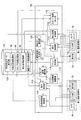
(写真プリント装置100における機能的説明)
次に、写真プリント装置100の機能的な構成について、図3に示すブロック図を参照しながら説明する。同図に示すように、写真プリント装置100は、前記したタッチパネル5a・5b・5c、カメラユニット4a・4bに加えて、制御装置41、電源装置42、課金処理部43、照明装置44、IDタグリーダ/ライタ45、プリンタ(画像出力手段)46を備えている。
(Functional Description in Photo Printing Apparatus 100)
Next, the functional configuration of the
制御装置41は、写真プリント装置100内における上述した各種構成の動作を統括的に制御するものである。この制御装置41は、例えばPC(Personal Computer)ベースのコンピュータによって構成される。そして、各種構成の動作制御は、制御プログラムをコンピュータに実行させることによって行われる。このプログラムは、例えばCD−ROM(Compact Disc Read Only Memory)などのリムーバブルメディアに記録されているものを読み出して使用する形態であってもよいし、ハードディスクなどにインストールされたものを読み出して使用する形態であってもよい。また、この制御装置41がインターネットなどの通信ネットワークに接続された構成とする場合、この通信ネットワークを介して上記プログラムをダウンロードしてハードディスクなどにインストールして実行する形態なども考えられる。
The
電源装置42は、写真プリント装置100内における上述した各種構成に対して電力供給を行うためのものである。
The
課金処理部43は、コイン投入口8からの代金投入、およびコイン返却口9におけるコイン返却処理などを制御するものであり、利用者から徴収する課金に関する処理を行うブロックである。課金処理部43による課金状況に応じて、制御装置41が該当利用者に対する動作を制御する。
The
照明装置44は、前記したストロボ光源、蛍光管などに相当するものであり、撮影時にフラッシュとして機能したり、通常時の照明としても機能したりするものである。制御装置41は、照明装置44に対して、写真撮影の瞬間にフラッシュ照明を行わせるなどの制御を行う。
The illuminating
IDタグリーダ/ライタ45およびプリンタ46は、プリンタユニットを構成しており、このプリンタユニットに対して、写真プリントの出力媒体となるプリント紙(プリント媒体)48およびIDタグ(識別媒体)47がプリント紙ユニット(プリント媒体ユニット)49としてセットで納入されるようになっている。
An ID tag reader /
なお、プリント紙48としては、通常の紙状媒体である紙状シートであってもよいし、粘着シートおよび該粘着シールの粘着面に貼り付けられている剥離シートからなるシールシートであってもよい。
The printed
プリンタ46は、印刷すべき画像のデータが制御装置41から送られてくると、そのデータに基づいてプリント紙(プリント媒体)48に印刷を行うものである。このプリンタ46としては、例えば昇華型プリンタが用いられる。なお、昇華型プリンタを用いる場合には、プリント紙48およびIDタグ47に加えて、昇華型用インクフィルムがセットになって納入されることになる。
When image data to be printed is sent from the
IDタグリーダ/ライタ45は、IDタグ47に記録されている各種識別情報を読み出して制御装置41に出力する。IDタグ47は、メモリ機能を有するICチップなどによって構成されるものである。上記識別情報としては、固有ID、用紙枚数、用紙種類、および、インク固有の色情報(インクフィルムがセットとなっている場合)などが挙げられる。
The ID tag reader /
IDタグ47としては、無線によりデータ通信を行うことが可能な非接触型IDタグと、端子が設けられた接触型IDタグとがあり、IDタグリーダ/ライタ45としては、これらのどちらか一方あるいは両方に対応したものとなる。
The
制御装置(制御手段)41は、撮影画像処理部50、編集画像処理部51、記憶部52、印刷制御部(画像出力制御手段)53を備えている。
The control device (control unit) 41 includes a captured
撮影画像処理部50は、カメラユニット4a・4b、タッチパネル5a・5bの動作制御を行うためのブロック、つまり、第一撮影空間R1、第二撮影空間R2における撮影処理、画像処理を実現するためのブロックであり、その詳細については後述する。
The photographed
編集画像処理部51は、タッチパネル5cの動作制御を行うためのブロックである。つまり、タッチパネル5cに表示されている画像に対し、利用者が落書きなどの編集処理を行う場合の制御を行うブロックである。
The edited
なお、撮影画像処理部50および編集画像処理部51は、上記したように、それぞれ相当する処理を行うプログラムをコンピュータが実行することによって実現されるものである。
Note that, as described above, the captured
記憶部(記憶手段)52は、上記したハードディスクなどの不揮発性の記憶装置によって構成されるものである。この記憶部52に記憶される内容としては、上記した制御プログラム、OS(Operating System)プログラム、およびその他各種プログラム、カメラユニット4a・4bにおける動作設定値、カメラユニット4a・4bが撮影している画像から取得した静止画像のデータ、印刷用画像のデータ、編集画像処理部51において編集した印刷用画像のデータなどが挙げられる。上記のカメラユニット4a・4bにおける動作設定値としては、装置出荷時やメンテナンス時などに設定されるホワイトバランスの値、撮影画像の明暗などを調整する際の画像処理に関する各種パラメータ値などが挙げられる。
The storage unit (storage means) 52 is configured by a nonvolatile storage device such as the hard disk described above. The contents stored in the
印刷制御部53は、印刷対象となる印刷用画像のデータを、プリンタ46の形式に適合したデータに変換し、この変換したデータをプリンタ46に出力し、プリント制御を行うブロックである。また、印刷制御部53は、IDタグリーダ/ライタ45で読みとった識別情報に基づいて、装着されたプリント紙48およびインクフィルムが、当該写真プリント装置100において利用可能なものであるかを判定し、利用可能である場合にのみプリンタ46を動作させる制御を行う。すなわち、写真プリント装置100において指定されているプリント紙およびインクフィルム以外は使用できないように設定されていることになる。
The
また、印刷制御部53は、IDタグ47に記録されている用紙枚数情報に基づいて、プリント紙48を使用するごとに用紙枚数をカウントダウンしていくことによって、残りの用紙枚数を把握する。よって、残りの用紙枚数が少なくなってきた際に、これを表示手段などによって警告するような構成としておけば、利用者の利用中にプリント紙切れを起こすというような不具合を回避することが可能となる。なお、印刷制御部53は、用紙枚数をカウントダウンする際には、IDタグ47に記録されている用紙枚数情報も書き換えるようにする。これにより、プリント紙48を使い切った場合には、IDタグ47に記録されている用紙枚数情報も0となり、このIDタグ47を無効にすることが可能となる。
Also, the
また、印刷制御部53は、IDタグ47に記録されている用紙種類情報や、インク固有の色情報を読み出すことによって、これらを考慮して画像データの色成分などを補正することにより、その用紙やインクフィルムに的確な画像出力を行うこと処理を行うこともできる。
Further, the
なお、上記の例では、IDタグを利用して利用可能なプリント紙であるか否かを確認するようになっているが、これに限定するものではなく、例えば、プリント紙およびインクフィルムを梱包する梱包材などにプリントされているバーコードなどを利用して確認するような構成としてもよい。しかしながら、バーコードを用いる場合には、含めることのできる情報量が少ないことや、例えば用紙枚数のカウントダウンによる情報の書き換えができない、などの問題がある。 In the above example, the ID tag is used to check whether the print paper can be used. However, the present invention is not limited to this. For example, the print paper and the ink film are packed. The configuration may be such that confirmation is performed using a barcode printed on a packing material or the like. However, when a barcode is used, there are problems that the amount of information that can be included is small and that information cannot be rewritten by counting down the number of sheets, for example.
〔実施の形態1〕
(実施の形態1の概略)
つぎに、本発明の実施の一形態について、図面に基づいて説明する。本実施の形態では、第一撮影空間R1において、写真撮影した静止画像を加工してスタンプ画像を作成する(スタンプ画像作成処理)。そして、第二撮影空間R2において、カメラユニット4bによってリアルタイムで撮影されている動画上に上記スタンプ画像を合成して、タッチパネル5bに表示する(合成撮影処理)。さらに、利用者が写真撮影のタイミングを指定すると、タッチパネル5bに表示されている画像から、印刷用静止画像が設定され、この印刷用静止画像に基づいた画像がプリント紙48上に印刷される。以下では、上述した処理を実現するための構成を説明する。
[Embodiment 1]
(Outline of Embodiment 1)
Next, an embodiment of the present invention will be described with reference to the drawings. In the present embodiment, a stamp image is created by processing a still image taken in the first shooting space R1 (stamp image creation processing). Then, in the second shooting space R2, the stamp image is synthesized on the moving image shot in real time by the
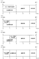
(撮影画像処理部50における機能的説明)
図1は、上述した撮影画像処理部50の各構成要素の機能を示したブロック図である。なお、以下では、記憶部52、タッチパネル5a、タッチパネル5bについても、撮影画像処理部50と関連する機能のみ説明する。
(Functional Description in Captured Image Processing Unit 50)
FIG. 1 is a block diagram showing the function of each component of the captured
撮影画像処理部50は、表示制御部61、静止画像取得部62、スタンプ画像加工部63、合成画像調整部64、表示制御部65、印刷用画像取得部66、スタンプ画像選択部67、選択画面生成部75を備えている。また、記憶部52は、静止画像記憶部68、スタンプ画像記憶部69、印刷用画像記憶部70を備えている。
The captured
また、第一撮影空間R1のタッチパネル5aは表示部71および入力部72から構成され、第二撮影空間R2のタッチパネル(表示手段)5bは表示部73および入力部74から構成されている。
The
ここで、表示部71は、第一撮影空間R1における処理に必要な様々な画像を利用者に対して表示するタッチパネル5aの表示手段である。表示部(表示手段)73は、第二撮影空間R2における処理に必要な様々な画像を利用者に対して表示するタッチパネル5bの表示手段である。
Here, the
また、入力部72は、第一撮影空間R1の利用者が処理の進行に応じて必要な情報を入力するタッチパネル5aの入力手段である。入力部74は、第二撮影空間R2の利用者が処理の進行に応じて必要な情報を入力するタッチパネル5bの入力手段である。なお、入力部72・74は、利用者がタッチパネル5a・5bの表示手段に接触し、またはタッチペン6a・6bがタッチパネル5a・5bの表示手段に接触することによって、利用者からの情報を入力する。
The
表示制御部61は、第一撮影空間R1におけるスタンプ画像作成処理についての各種メッセージや各種画像などを表示部71に表示する制御を行う。また、表示制御部61は、カメラユニット(第一撮影手段)4aが撮影している動画のデータを入力し、この動画を表示部71に表示する制御を行うブロックである。
The
静止画像取得部62は、利用者が指示する写真撮影のタイミングを示すタイミング識別情報を入力部72から取得し、このタイミングで表示制御部61が入力している動画のデータから静止画像を取得するブロックである。また、静止画像取得部62は、取得した静止画像のデータを静止画像記憶部68に保存する。
The still
スタンプ画像加工部(画像加工手段)63は、画像加工対象となる静止画像のデータを静止画像記憶部68から読み出す。そして、スタンプ画像加工部63は、利用者の画像加工指示を示す加工指示情報を入力部72から受け取って、この加工指示情報に基づいて、読み出した静止画像のデータを加工してスタンプ画像のデータを作成するブロックである。ここで、スタンプ画像とは、静止画像から一部領域を指定、または静止画像を拡大または縮小等によって得られる画像であって、ある動画または静止画像の一部領域上に貼り付けて表示、印刷される画像をいう。
The stamp image processing unit (image processing unit) 63 reads out still image data to be processed from the still
なお、画像加工対象となる静止画像のデータは、リアルタイムでスタンプ画像加工部63から表示制御部61に送信される。これにより、利用者の画像加工指示に基づいて加工されているスタンプ画像がリアルタイムで表示される。さらに、スタンプ画像加工部63は、加工後のスタンプ画像のデータをスタンプ画像記憶部69に保存する。
The still image data to be processed is transmitted from the stamp
表示制御部(表示制御手段)65は、第二撮影空間R2における写真撮影についての各種メッセージや各種画像などを表示部73に表示する制御を行うブロックである。また、表示制御部65は、利用者に選択されたスタンプ画像のデータを入力すると、カメラユニット(第二撮影手段)4bが撮影している動画に対しこのスタンプ画像を合成して、表示部73に表示する制御を行うブロックである。
The display control unit (display control means) 65 is a block that performs control for displaying various messages, various images, and the like regarding photography in the second imaging space R2 on the
選択画面生成部75は、スタンプ画像記憶部69に保存された全てのスタンプ画像のデータを読み出し、この読み出した全てのスタンプ画像を羅列したスタンプ画像選択画面のデータを生成し、表示制御部65に送信するブロックである。これにより、表示制御部65が上記スタンプ画像選択画面を表示部73に表示する。
The selection
スタンプ画像選択部67は、利用者に選択されたスタンプ画像を識別するスタンプ画像選択情報を入力部74から受け取ると、選択されたスタンプ画像のデータのみをスタンプ画像記憶部69から読み出し、読み出したスタンプ画像のデータを表示制御部65に入力するブロックである。
When the stamp
合成画像調整部64は、利用者からの画像調整指示を示す画像調整情報を入力部74から受け取ると、表示制御部65によって合成される動画に対して補正を行うためのブロックである。なお、この補正は、カメラユニット4bに撮影されている動画上に合成されるスタンプ画像の配置、大きさ等を調整する処理である。
The composite
印刷用画像取得部66は、利用者が指示する写真撮影のタイミングを示すタイミング識別情報を入力部74から取得し、このタイミングで表示部73に表示されている動画のデータから印刷用静止画像を取得し、この印刷用静止画像のデータを印刷用画像記憶部70に保存するブロックである。つまり、印刷用画像取得部66は、表示制御部65によってスタンプ画像が合成された動画のデータから、印刷用静止画像を取得することになる。
The print
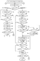
(全体処理の流れ)
つぎに、写真プリント装置100における処理の流れについて、図4に示すフローチャートを参照しながら説明する。なお、ここでは、複数の利用者からなるグループが写真プリント装置100を利用する場合について説明する。
(Overall process flow)
Next, the flow of processing in the
まず、ステップ1(以降、S1のように称する)において、利用者がコイン投入口8から代金としてのコインを投入する。コインの投入がない場合は、S1が繰り返される(S2,NO)。そして、課金処理部43によって、コインの投入の完了が判断されると(S2,YES)、利用者は2組に別れて第一撮影空間R1および第二撮影空間R2に入場する。なお、ここで、利用者に対し、図示しないスピーカによって、2組に別れて第一撮影空間R1および第二撮影空間R2に入場するように促してもよい。
First, in step 1 (hereinafter referred to as S1), the user inserts a coin as a price from the
そして、S3において、スタンプ画像作成処理および合成撮影処理が開始される。ここで、第一撮影空間R1においてスタンプ画像作成処理が行われ、第二撮影空間R2において合成撮影処理が行われる。なお、スタンプ画像作成処理および合成撮影処理の詳細については後述する。 In S3, stamp image creation processing and composite shooting processing are started. Here, a stamp image creation process is performed in the first shooting space R1, and a composite shooting process is performed in the second shooting space R2. The details of the stamp image creation process and the composite shooting process will be described later.
そして、S4において、スタンプ画像作成処理および合成撮影処理の終了が判定され、終了していない場合には(S4,NO)、S3の処理が繰り返し行われる。スタンプ画像作成処理および合成撮影処理の終了が確認されると(S4,YES)、利用者は編集処理用空間R3に移動し、タッチパネル5cを用いて編集処理が開始される(S5)。
In S4, the end of the stamp image creation process and the composite shooting process is determined. If not completed (S4, NO), the process of S3 is repeated. When it is confirmed that the stamp image creating process and the composite photographing process are finished (S4, YES), the user moves to the editing process space R3, and the editing process is started using the
さらに、S6において編集処理が終了したか否かが判定され、終了していない場合には(S6,NO)、S5に戻って編集処理が継続される。編集処理は、利用者によって編集終了の指示が出されるか、あるいは編集処理に割り当てられた残り時間がなくなった場合に終了することになる。 Further, in S6, it is determined whether or not the editing process has been completed. If it has not been completed (S6, NO), the process returns to S5 and the editing process is continued. The editing process ends when the user gives an instruction to end editing or when the remaining time allocated to the editing process runs out.
編集処理の終了が確認されると(S6,YES)、編集が施された印刷用画像のデータが印刷制御部53に伝送され、印刷制御部53は、このデータに基づいてプリンタ46の印刷動作を制御する。これにより、プリント紙48上に上記印刷用画像を出力でき、このプリント紙48がプリント排出口10から排出される(S7)。以上のシーケンスによって、ある複数利用者からなるグループによる撮影から編集、出力に至るプレイ動作が終了する。
When the end of the editing process is confirmed (S6, YES), the edited print image data is transmitted to the
(スタンプ画像作成処理および合成撮影処理)
つぎに、S3で示したスタンプ画像作成処理、および合成撮影処理の詳細を図5に基づいて説明する。なお、図5におけるS11〜S18のスタンプ画像作成処理と、S19〜S33の合成撮影処理とは、同時に開始される。そして、S11〜S18のスタンプ画像作成処理、S19〜S33の合成撮影処理には、それぞれ同じ制限時間が割り当てられている。
(Stamp image creation processing and composite shooting processing)
Next, details of the stamp image creating process and the composite photographing process shown in S3 will be described with reference to FIG. Note that the stamp image creation processing in S11 to S18 and the composite shooting processing in S19 to S33 in FIG. 5 are started simultaneously. The same time limit is assigned to each of the stamp image creation processing in S11 to S18 and the composite photographing processing in S19 to S33.
まず、第一撮影空間R1で実行されるスタンプ画像作成処理について説明する。第一撮影空間R1に入場した利用者は、カメラユニット4aにより撮影されている。そして、表示制御部61は、カメラユニット4aが撮影している動画のデータを入力し、この動画(ライブビュー)をタッチパネル5aに表示する(S11)。ここで、表示制御部61は、上記ライブビューのみならず、撮影ボタンをタッチパネル5aに表示する(S11)。また、「撮影ボタンを押してね」という写真撮影を促すメッセージを表示してもよい。ここで、S11におけるライブビューを表示したタッチパネルの例を図13(a)(b)に示す。なお、図13(a)は、ズーム機能を用いずに撮影されているライブビューを表示したタッチパネルの例であり、図13(b)は、ズーム機能を用いて撮影されているライブビューを表示したタッチパネルの例である。
First, the stamp image creation process executed in the first shooting space R1 will be described. The user who entered the first shooting space R1 is shot by the
そして、利用者が写真撮影のタイミングで上記撮影ボタンに触れると(S12,YES)、S14において利用者の写真撮影が行われる。具体的には、利用者が上記撮影ボタンに触れると、タッチパネル5aの入力部72がタイミング識別信号を静止画像取得部62に送信する。そして、静止画像取得部62が、このタイミング識別信号によって上記写真撮影のタイミングを検出する。さらに、静止画像取得部62は、このタイミングで表示制御部61が入力している動画のデータから静止画像を取得し、この静止画像のデータを静止画像記憶部68に保存する。
When the user touches the shooting button at the timing of taking a photograph (S12, YES), a photograph of the user is taken in S14. Specifically, when the user touches the shooting button, the
なお、利用者が上記撮影ボタンに触れない場合であっても(S12,NO)、ライブビューの表示開始から所定時間が経過するとタイムオーバーと判断され(S13,YES)、S14において自動的に写真撮影が行われる。なお、ライブビューの表示開始から所定時間が経過していない場合、S11〜S12が繰り返される(S13,NO)。 Even when the user does not touch the shooting button (S12, NO), it is determined that the predetermined time has elapsed since the start of the live view display (S13, YES), and the photograph is automatically taken in S14. Is done. Note that if the predetermined time has not elapsed since the start of the live view display, S11 to S12 are repeated (S13, NO).
第一撮影空間R1における写真撮影が終了すると、写真撮影により得られた静止画像からスタンプ画像を作成する処理が行われる(S15)。このスタンプ画像の作成について説明すると以下のとおりである。 When the photography in the first photography space R1 is completed, a process of creating a stamp image from a still image obtained by photography is performed (S15). The creation of this stamp image will be described as follows.
まず、静止画像記憶部68に保存されている静止画像のデータがスタンプ画像加工部63によって読み出される。そして、スタンプ画像加工部63は、この静止画像のデータを表示制御部61に送信し、表示制御部61は、この静止画像をタッチパネル5aに表示する。
First, still image data stored in the still
ここで、利用者が、タッチペン6aを用いてスタンプ画像の作成を開始すると、タッチパネル5aの入力部72は、利用者の画像加工指示を示す加工指示情報をスタンプ画像加工部63に送る。そして、スタンプ画像加工部63は、この加工指示情報に基づいて、静止画像上におけるスタンプ画像として用いる領域を検知し、この領域のみを抽出してスタンプ画像を作成する。
Here, when the user starts creating a stamp image using the
このスタンプ画像の作成をさらに詳細に説明すると以下のとおりである。まず、タッチパネル5aには、図16(a)に示すようなスタンプ画像作成画面P1が表示される。このスタンプ画像作成画面P1には、加工対象となる静止画像P2およびフレーム画像aが表示されている。
The creation of the stamp image will be described in detail as follows. First, a stamp image creation screen P1 as shown in FIG. 16A is displayed on the
そして、利用者が、このスタンプ画像作成画面P1上における静止画像P2に対し、タッチペン6aを用いてフレーム画像aをスクロールさせ、スタンプ画像として用いる範囲をフレーム画像aで囲む(図16(a)参照)。これにより、スタンプ画像として用いる範囲を指定でき、フレーム画像aで囲まれている範囲がスタンプ画像として加工される。なお、図16(b)の上図に示すように、タッチパネル5a上のフレーム画像aに囲まれている領域に対してタッチペン6aを接触させながら移動させると、フレーム画像aの位置をスクロールさせることができる。そして、図16(b)の下図に示すように、タッチパネル5aからタッチペン6aを離すと、静止画像P2に対するフレーム画像aの位置が確定し、スタンプ画像として用いる範囲を決定できる。その後、スタンプ画像として用いる範囲が加工され、加工されたスタンプ画像が図16(a)の参照符Wの示すスタンプ画像表示領域に表示される。
Then, the user scrolls the frame image a using the
なお、利用者によるスタンプ画像の作成が所定時間内に行われない場合、スタンプ画像加工部63がスタンプ画像の作成を自動的に行ってもよい。例えば、スタンプ画像加工部63は、静止画像記憶部68から読み出した静止画像のうち、人物像(被写体)の顔面領域を検出し、この領域のみを抽出してスタンプ画像を作成してもよい。
If the user does not create the stamp image within a predetermined time, the stamp
以上のようにして作成されたスタンプ画像のデータは、スタンプ画像加工部63によってスタンプ画像記憶部69に保存される(S16)。その後、タッチパネル5aに終了ボタンが表示され、利用者がこの終了ボタンを押すと、第一撮影空間R1におけるスタンプ画像作成処理が終了する(S17,YES)。
The stamp image data created as described above is stored in the stamp
また、利用者がこの終了ボタンを押さない場合(S17,NO)、残り制限時間がゼロになるまで、以上のスタンプ画像作成処理を繰り返すことができ(S18,NO)、これにより、複数のスタンプ画像を作成できる。そして、残り制限時間がゼロと判断されると、スタンプ画像作成処理を終了する(S18,YES)。 If the user does not press the end button (S17, NO), the above-described stamp image creation process can be repeated until the remaining time limit becomes zero (S18, NO). You can create an image. If it is determined that the remaining time limit is zero, the stamp image creation process is terminated (S18, YES).
なお、スタンプ画像作成処理を繰り返す場合、二以上の静止画像が静止画像記憶部68に保存されることになるが、この場合、S15において二以上の静止画像から様々なスタンプ画像を作成することも可能である。例えば、図14に示すように、まず、静止画像P3からスタンプ画像Aを作成し、ズーム機能を用いて撮影された静止画像P4からスタンプ画像Bを作成する。なお、スタンプにする領域の指定は、上述したフレーム画像aによって指定する処理であってもよいし、スタンプにする領域以外の部分を透明ペンで塗り潰す処理であってもよい。さらに、図14に示すように、作成したスタンプ画像AおよびBを保存し、保存したスタンプ画像を合成すれば、新たなスタンプ画像Dを加工することができる。
When the stamp image creation process is repeated, two or more still images are stored in the still
ここで、以上のスタンプ画像の作成を行うためのスタンプ画像作成画面の例を図15に示す。図15において、参照符P5はスタンプ画像作成画面を示し、参照符Xはスタンプ画像表示領域を示し、参照符Tはスタンプ画像を作成するための作業領域を示す。なお、スタンプ画像表示領域Xには、作成されたスタンプ画像AおよびB、予め用意されている装飾スタンプ画像Cが表示されている。 Here, an example of a stamp image creation screen for creating the above stamp image is shown in FIG. In FIG. 15, a reference symbol P5 indicates a stamp image creation screen, a reference symbol X indicates a stamp image display area, and a reference symbol T indicates a work area for creating a stamp image. In the stamp image display area X, the created stamp images A and B and a decorative stamp image C prepared in advance are displayed.
利用者は、スタンプ画像表示領域Xに表示されている各スタンプ画像を任意に組み合わせることによって、新たなスタンプ画像を作成できる。例えば、利用者が、スタンプ画像表示領域に示されているスタンプ画像のうち、スタンプ画像Aにタッチペン6aを接触させ、その後タッチペン6aを作業領域Tに接触させると、スタンプ画像Aが作業領域Tに表示される。そして、利用者は、スタンプ画像Bにタッチペン6aを接触させ、その後タッチペン6aを作業領域Tに接触させると、スタンプ画像Bが作業領域Tに表示される。この結果、作業領域Tには、スタンプ画像Aとスタンプ画像Bとを合成したスタンプ画像Dが表示されることとなる。そして、新たに作成されたスタンプ画像Dはスタンプ画像表示領域に追加される(図15における参照符Y)。
The user can create a new stamp image by arbitrarily combining the stamp images displayed in the stamp image display area X. For example, when the user brings the
つぎに、第二撮影空間R2で実行される合成撮影処理について説明する。第二撮影空間R2においては、カメラユニット4bが利用者を撮影し続けている。そして、表示制御部65は、この撮影により取得されている動画(ライブビュー)をタッチパネル5bに表示する(S19)。なお、表示制御部65は、上記動画のみならず、撮影ボタンをタッチパネル5bに表示する(S19)。
Next, the composite shooting process executed in the second shooting space R2 will be described. In the second shooting space R2, the
S19の後、表示制御部65は、スタンプ画像記憶部69においてスタンプ画像が記憶されているか否かを判定する。スタンプ画像が記憶されている場合(S20,YES)、表示制御部65は、上記ライブビューと共に合成ボタンをタッチパネル5bに表示する(S21)。なお、図17は、S21において、ライブビューおよび合成ボタンを表示したタッチパネルの例を示した図である。
After S19, the
ここで、利用者が上記合成ボタンにタッチすると(S22,YES)、選択画面生成部75は、スタンプ画像選択画面のデータを生成し、表示制御部65に送信する。これにより、図18(a)に示すように、ライブビュー(参照符Q)と共に、スタンプ画像選択画面(参照符V)がタッチパネル5bに表示される(S23)。具体的には、利用者が上記合成ボタンにタッチすると、タッチパネル5bの入力部74が選択画面生成部75に選択画面生成指示情報を送信する。そして、選択画面生成部75は、この選択画面生成指示情報を検知すると、スタンプ画像記憶部69に保存された全てのスタンプ画像のデータからスタンプ画像選択画面のデータを生成し、表示制御部65に送信する。
Here, when the user touches the composite button (S22, YES), the selection
そして、利用者が、スタンプ画像選択画面に示されているスタンプ画像のうち、所望のスタンプ画像にタッチすると、利用者の指定するスタンプ画像が選択される(S24,YES)。具体的には、利用者が、タッチパネル5bに表示されている所望のスタンプ画像にタッチすると、タッチパネル5bの入力部74がスタンプ画像選択情報をスタンプ画像選択部67に送信する。そして、スタンプ画像選択部67は、このスタンプ画像選択情報の示すスタンプ画像のデータをスタンプ画像記憶部69から読み出し、表示制御部65に入力する。
Then, when the user touches a desired stamp image among the stamp images displayed on the stamp image selection screen, a stamp image designated by the user is selected (S24, YES). Specifically, when the user touches a desired stamp image displayed on the
ここで、利用者によってスタンプ画像の指定がない場合(S24,NO)、スタンプ画像選択画面の表示から所定時間が経過したか否かが判断され、所定時間を経過していない場合はS23〜S24が繰り返され(S25,NO)、所定時間を経過している場合はタイムオーバーと判断される(S25,YES)。この場合、S26においてスタンプ画像選択部67がスタンプ画像を自動選択する。
Here, if the stamp image is not designated by the user (S24, NO), it is determined whether or not a predetermined time has elapsed since the display of the stamp image selection screen. If the predetermined time has not elapsed, S23 to S24 are determined. Is repeated (S25, NO), and if the predetermined time has elapsed, it is determined that the time is over (S25, YES). In this case, in S26, the stamp
ここで、S26の処理について詳細に説明する。なお、スタンプ画像記憶部69は、各スタンプ画像のデータを要素とした配列を構成しているものとする。また、要素ごとに変数n(n:1,2,3,・・・,N)が添字されている。まず、スタンプ画像選択部67は、式1を演算して変数nを求める。
変数n=int〔rnd×N〕+1・・・・・・(式1)
int〔〕:小数点以下を切り捨てる関数
rnd:0を超え、1未満である乱数(小数に限る)
N:配列の要素数
そして、スタンプ画像選択部67は、求めた変数nが添字されているスタンプ画像のデータを自動選択する。このようにして、S26の処理が実行される。
Here, the process of S26 will be described in detail. It is assumed that the stamp
Variable n = int [rnd × N] +1 (Equation 1)
int []: function for rounding down decimal places rnd: random number greater than 0 and less than 1 (limited to decimals)
N: Number of elements in array The stamp
スタンプ画像が選択された後、表示制御部65は、スタンプ画像選択部67から入力したスタンプ画像を、カメラユニット4bから取得されている動画上に合成し、合成した動画(ライブビュー)をタッチパネル5bに表示させる(S27)。ここで、図18(b)は、S27において、スタンプ画像を合成したライブビュー(参照符L)を表示したタッチパネルの例を示した図である。
After the stamp image is selected, the
S27の後、利用者は、動画上に合成されているスタンプ画像の配置を調整できる(S28)。具体的には、利用者がタッチペン6bを用いて、タッチパネル5bに表示されている動画上におけるスタンプ画像を配置すべき箇所を指定する。これにより、タッチパネル5bの入力部74は、画像調整情報を合成画像調整部64に送信する。そして、合成画像調整部64は、この画像調整情報に応じて、タッチパネル5bに表示されている動画上における利用者の指定した箇所にスタンプ画像が合成されるよう、表示制御部65を制御する。
After S27, the user can adjust the arrangement of the stamp image synthesized on the moving image (S28). Specifically, the user uses the
なお、S24のスタンプ画像の選択、およびS27のスタンプ画像の合成は、タッチペン6bを用いて行われても構わない。具体的には、S24において、利用者は、スタンプ画像選択画面(図18(a)の参照符V)に表示されているスタンプ画像のうち、所望のスタンプ画像にタッチペン6bを接触させることによって、スタンプ画像を選択する。その後、S27において、利用者が、タッチパネル5bに表示されているライブビュー(図18(a)の参照符Q)上における所望の位置にタッチペン6bを接触され、接触された箇所に選択されたスタンプ画像が合成されるように制御してもよい。
Note that the selection of the stamp image in S24 and the composition of the stamp image in S27 may be performed using the
また、合成画像調整部64が、利用者からの指示に応じ、合成表示されるスタンプ画像の大きさを調整する制御を行うようにしてもよい。さらに、合成画像調整部64が、利用者からの指示に応じ、合成表示されるスタンプ画像の領域の形状(丸形状、四角形状、三角形状等)を変更する制御を行うようにしてもよい。
Further, the composite
その後、利用者が写真撮影のタイミングで上記撮影ボタンに触れると(S29,YES)、S31において利用者の写真撮影が行われる。具体的には、利用者が上記撮影ボタンに触れると、タッチパネル5bの入力部74がタイミング識別信号を印刷用画像取得部66に送信する。そして、印刷用画像取得部66が、このタイミング識別信号によって上記写真撮影のタイミングを検出する。そして、印刷用画像取得部66は、表示制御部65がタッチパネル5bに表示している合成後の動画のデータから上記タイミングで静止画像を取得し、この静止画像のデータを印刷用画像記憶部70に保存する。
Thereafter, when the user touches the shooting button at the timing of taking a photograph (S29, YES), a photograph of the user is taken in S31. Specifically, when the user touches the shooting button, the
なお、利用者が上記撮影ボタンに触れない場合であっても(S29,NO)、撮影ボタンの表示(S19)から所定時間が経過するとタイムオーバーと判断され(S30,YES)、S31において自動的に写真撮影が行われる。なお、タイムオーバーと判断されない場合(S30,NO)、S27〜S30が繰り返される。 Even if the user does not touch the shooting button (S29, NO), it is determined that a predetermined time has elapsed from the shooting button display (S19) (S30, YES), and automatically in S31. A photo is taken. If it is not determined that the time is over (S30, NO), S27 to S30 are repeated.
その後、タッチパネル5bに終了ボタンが表示され、利用者がこの終了ボタンを押すと、第二撮影空間R2における合成撮影処理が終了する(S32,YES)。
Thereafter, an end button is displayed on the
また、利用者がこの終了ボタンを押さない場合(S32,NO)、残り制限時間がゼロになるまで、以上の処理を繰り返すことができる(S33,NO)。そして、残り制限時間がゼロと判断されると、合成撮影処理を終了する(S33,YES)。 If the user does not press the end button (S32, NO), the above process can be repeated until the remaining time limit becomes zero (S33, NO). If it is determined that the remaining time limit is zero, the composite photographing process is terminated (S33, YES).
その後、印刷用画像記憶部70に保存されている印刷用画像のデータは、編集画像処理部51によって編集され(S5)、印刷制御部53が、この編集された印刷用画像のデータに基づいてプリンタ46を制御する。これにより、上記印刷用画像に基づいた画像をプリント紙48上に出力できる。
Thereafter, the print image data stored in the print
以上のように、表示制御部65は、カメラユニット4bによって撮影されている動画をタッチパネル5bにリアルタイム表示すると同時に、カメラユニット4aで撮影された加工済の静止画像(スタンプ画像)をこの動画上に合成し、タッチパネル5bに表示している。そして、プリンタ46は、タッチパネル5bに表示されているスタンプ画像合成後の動画に基づいて、プリント紙48上に画像を出力している。したがって、第二撮影空間R2にいる利用者は、タッチパネル5bに表示されているスタンプ画像合成後の動画を確認してから、この動画をプリント紙48上に印刷できるため、合成後の画像を予測しながらの写真撮影が可能となる。
As described above, the
また、以上の合成撮影処理において、スタンプ画像記憶部69にスタンプ画像が保存されていない場合(S20,NO)、また、スタンプ画像が保存されていても利用者が上記合成ボタンを押さない場合(S22,NO)、第二撮影空間R2の利用者は、スタンプ画像を合成しない通常の写真撮影を行うことができる。具体的には、S20またはS22においてNOと判定されると、S29に移行し、撮影ボタンを押したか否かが判断される。ここで、利用者が上記撮影ボタンに触れると(S29,YES)、S31において利用者の写真撮影が行われる。つまり、印刷用画像取得部66は、カメラユニット4bが取得し、タッチパネル5bに表示されている動画(スタンプ画像が合成されていない動画)に基づいて印刷用画像のデータを取得し、この印刷用画像のデータを印刷用画像記憶部70に保存する。したがって、第二撮影空間R2における合成撮影処理では、スタンプ画像を合成しない写真撮影(通常の写真撮影)も行うことができる。これにより、第一撮影空間R1のスタンプ画像作成処理においてスタンプ画像がスタンプ画像記憶部69に保存されるまでの間、第二撮影空間R2の利用者は、スタンプ画像を合成しない通常の写真撮影を行うことができる。
Further, in the above composite shooting process, when the stamp image is not stored in the stamp image storage unit 69 (S20, NO), or when the user does not press the composite button even if the stamp image is stored ( (S22, NO), the user of the second shooting space R2 can perform normal photography without combining the stamp images. Specifically, if NO is determined in S20 or S22, the process proceeds to S29, and it is determined whether or not the photographing button is pressed. If the user touches the shooting button (S29, YES), the user is photographed in S31. That is, the print
また、S27において、カメラユニット4bから取得されると共にスタンプ画像が合成されている動画は、第二撮影空間R2のタッチパネル5bに表示されているが、第一撮影空間R1のタッチパネル5aにも表示してよい。具体的には、S16とS17との間において、表示制御部65が合成画像表示ボタンをタッチパネル5aに表示する。そして、第一撮影空間R1の利用者が、この合成画像表示ボタンにタッチすると、表示制御部65は、タッチパネル5aの入力部72からの指示に応じて、スタンプ画像が合成されている動画をタッチパネル5aに表示する。これにより、第二撮影空間R2の利用者のみならず、第一撮影空間R1の利用者に対しても、カメラユニット4bから取得され、スタンプ画像が合成されている動画を表示させることができる。
In S27, the moving image obtained from the
さらに、S28において、カメラユニット4bから取得される動画に対するスタンプ画像の合成位置の調整は、第二撮影空間R2の利用者が行っているが、第一撮影空間R1の利用者が行ってもよい。つまり、カメラユニット4bから取得され、スタンプ画像が合成されている動画をタッチパネル5aに表示した後、第一撮影空間R1の利用者が、タッチパネル5aに表示されている動画を確認しながら、動画上に合成されるスタンプ画像の配置を調整してもよい。具体的には、第一撮影空間R1の利用者が、タッチペン6aを用いて、タッチパネル5aに表示されている動画上におけるスタンプ画像を配置すべき箇所を指定する。これにより、タッチパネル5aの入力部72は、前記画像調整情報を合成画像調整部64に送信する。そして、合成画像調整部64は、この画像調整情報に応じて、表示されている動画上における利用者の指定した箇所にスタンプ画像が合成されるよう、表示制御部65を制御する。このようにすれば、スタンプ画像の合成位置の調整は、第一撮影空間R1の利用者も行うことができるため、第二撮影空間R2の利用者は、撮影ポーズを崩してまでこの調整作業を行う必要がなく、写真撮影に専念することができる。
Furthermore, in S28, adjustment of the composite position of the stamp image with the moving image acquired from the
つぎに、写真プリント装置100の利用形態の例を説明する。なお、以下では、スタンプ画像作成処理および合成撮影処理(S4)の夫々に割り当てられる制限時間をコイン投入から2分、編集処理(S6)の制限時間をコイン投入から4分、印刷処理の所要時間を1分とする。
Next, an example of a usage pattern of the
まず、複数の利用者からなるグループのうち、第一撮影空間R1に入場した利用者が、制限時間をフル活用してスタンプ画像作成処理を繰り返している間、第二撮影空間R2に入場した利用者が合成撮影処理を行う第一の利用形態が考えられる。この第一の利用形態によれば、第一撮影空間R1において複数のスタンプ画像を作成できる。そして、第二撮影空間R2の利用者は、上記複数のスタンプ画像から所望のスタンプ画像を選択し、自身が撮影されている動画上に選択したスタンプ画像を合成した画像をタッチパネル5bに表示させることができる。なお、第一の利用形態によれば、図6(a)に示すように、第一撮影空間R1におけるスタンプ画像作成処理と、第二撮影空間R2における合成撮影処理とを並行して実行し、かつ同時に終了していることになる。
First, the user who entered the first shooting space R1 out of the group consisting of a plurality of users entered the second shooting space R2 while repeating the stamp image creation process by making full use of the time limit. A first mode of use in which a person performs composite shooting processing is conceivable. According to this first usage pattern, a plurality of stamp images can be created in the first imaging space R1. Then, the user of the second shooting space R2 selects a desired stamp image from the plurality of stamp images, and causes the
但し、上記第一の利用形態によれば、第一撮影空間R1の利用者は制限時間をフル活用してスタンプ画像作成処理を行っているため、第一撮影空間R1の利用者と第二撮影空間R2の利用者とは同時に写真撮影を行うことができない。 However, according to the first mode of use, the user of the first shooting space R1 performs the stamp image creation process by fully utilizing the time limit, so the user of the first shooting space R1 and the second shooting space A user of the space R2 cannot take a photo at the same time.
これに対し、第一撮影空間R1に入場した一方の利用者が、スタンプ画像作成処理を制限時間経過前に終了し(図5のS17においてYES)、第二撮影空間R2に移動して他方の利用者と合流する第二の利用形態が考えられる。これにより、一方の利用者と他方の利用者とは同一のカメラユニット4bで同時に写真撮影を行える。
On the other hand, one user who entered the first shooting space R1 ends the stamp image creation process before the time limit has elapsed (YES in S17 in FIG. 5), moves to the second shooting space R2, and moves to the other shooting space R2. A second mode of use that merges with the user is conceivable. As a result, one user and the other user can simultaneously take a picture with the
また、第二の利用形態によれば、第一撮影空間R1に入場した一方の利用者が、自身の姿を示したスタンプ画像を作成し、その後、第二の撮影空間R2の利用者と合流して合成撮影を行っている。よって、グループ全員を被写体とした画像に対し、このグループにおける一部の利用者の顔を示したスタンプ画像を合成する処理が可能となる。なお、第二の利用形態によれば、図6(b)に示すように、第一撮影空間R1におけるスタンプ画像作成処理と第二撮影空間R2における合成撮影処理とを同時に開始し、スタンプ画像作成処理を合成撮影処理よりも先に終了させることになる。 Further, according to the second usage pattern, one user who entered the first shooting space R1 creates a stamp image showing his / her appearance, and then joins the user of the second shooting space R2. And doing composite photography. Therefore, it is possible to synthesize a stamp image showing the faces of some users in this group with an image in which all the groups are subjects. According to the second usage mode, as shown in FIG. 6B, stamp image creation processing in the first shooting space R1 and composite shooting processing in the second shooting space R2 are started at the same time, and stamp image creation is performed. The process ends before the composite shooting process.
また、第二の利用形態によれば、第一撮影空間R1におけるスタンプ画像作成処理と第二撮影空間R2における合成撮影処理とを同時に開始しているが、特に同時に開始する必要はない。 According to the second usage mode, the stamp image creation process in the first shooting space R1 and the composite shooting process in the second shooting space R2 are started at the same time, but it is not necessary to start them at the same time.
例えば、まず、複数の利用者からなるグループの全員が第二撮影空間R2に入場して合成撮影処理を開始し、合成撮影処理およびスタンプ画像作成処理の制限時間経過前に、このグループにおける一部の利用者が第一撮影空間R1に移動してスタンプ画像作成処理を開始する第三の利用形態も考えられる。つまり、第三の利用形態によれば、図6(c)に示すように、第二撮影空間R2における合成撮影処理が先に開始され、その後、第二撮影空間R2における合成撮影処理と第一撮影空間R1におけるスタンプ画像作成処理とが並行して行われる。 For example, first, all members of a group consisting of a plurality of users enter the second shooting space R2 to start the composite shooting process, and before the time limit for the composite shooting process and the stamp image creation process elapses, A third usage mode in which the user moves to the first shooting space R1 and starts the stamp image creation process is also conceivable. That is, according to the third usage pattern, as shown in FIG. 6C, the composite photographing process in the second photographing space R2 is started first, and then the composite photographing process in the second photographing space R2 and the first. The stamp image creation process in the imaging space R1 is performed in parallel.
この第三の利用形態によれば、スタンプ画像作成処理の開始前の合成撮影処理において、スタンプ画像記憶部69にスタンプ画像が保存されていない状態である。したがって、スタンプ画像作成処理の開始前の合成撮影処理では、スタンプ画像を合成した撮影を行うことができず、スタンプ画像を合成しない写真撮影(通常の写真撮影)を行うことになる(図5のS20においてNO)。そして、スタンプ画像作成処理の開始後は、合成撮影処理においてスタンプ画像を合成した撮影を行うことができる。
According to the third usage mode, the stamp image is not stored in the stamp
また、利用者が1人である場合、当該利用者が、第一撮影空間R1に入場してスタンプ画像作成処理を行った後、制限時間経過前にスタンプ画像作成処理を終了して(図5のS17においてYES)、第二撮影空間R2に移動して合成撮影処理を行う第四の利用形態も考えられる。つまり、第四の利用形態によれば、図6(d)に示すように、第一撮影空間R1におけるスタンプ画像作成処理が先に開始され、スタンプ画像作成処理の終了と共に、第二撮影空間R2における合成撮影処理が開始されることとなる。 If there is only one user, the user enters the first shooting space R1 and performs the stamp image creation process, and then ends the stamp image creation process before the time limit has elapsed (FIG. 5). In S17, YES), a fourth usage mode in which the composite shooting process is performed by moving to the second shooting space R2 is also conceivable. That is, according to the fourth usage pattern, as shown in FIG. 6D, the stamp image creation process in the first shooting space R1 is started first, and at the end of the stamp image creation process, the second shooting space R2 is started. The composite photographing process in is started.
この第四の利用形態によれば、1人の利用者であっても本実施の形態の写真プリント装置を利用できる。また、当該利用者が第二撮影空間R2に移動して合成撮影処理を行っている間、第一撮影空間R1において別の利用者がスタンプ画像作成処理を行えるようにすれば、一台の写真プリント装置100でいわゆる二重接客を行うことが可能になる。
According to the fourth usage mode, even the single user can use the photo printing apparatus of the present embodiment. Further, if the user moves to the second shooting space R2 and performs the composite shooting process while another user can perform the stamp image creation process in the first shooting space R1, a single photo can be obtained. The
また、本実施の形態の写真プリント装置100によれば、タッチパネル5bに表示される動画に対して、加工したスタンプ画像を合成することになる。したがって、利用者は、所望の加工処理を施したスタンプ画像を上記動画上に合成し、合成した画像をタッチパネル5bで確認しながら写真撮影を行うことが可能になる。
Further, according to the
さらに、本実施の形態に係る写真プリント装置100のカメラユニット4aは、ズーム機能を有する撮影用カメラから構成されていてもよく、これにより予め拡大または縮小した静止画像を取得できる。したがって、スタンプ画像加工部63によるスタンプ画像作成処理の際、静止画像のサイズを変更する処理を省略することができる。
Furthermore, the
また、本実施の形態の写真プリント装置100において、第一撮影空間R1をクロマキー処理専用の撮影環境にしても構わない。これにより、第二撮影空間R2において撮影されている動画に対し、第一撮影空間R1において写真撮影された静止画像をクロマキー処理によって合成することができる。
In the
〔実施の形態2〕
(実施の形態2の概略)
つぎに、本発明に係る他の実施の一形態について、図面に基づいて説明する。なお、本実施の形態の構成は、実施の形態1の構成と比べて、撮影画像処理部の各構成要素が異なるだけである。したがって、説明の便宜上、実施の形態2では、撮影画像処理部の各構成要素に対してのみ異なる部材番号を付して説明し、その他の構成については実施の形態1と同一の部材番号を付して、必要のない説明については省略する。
[Embodiment 2]
(Outline of Embodiment 2)
Next, another embodiment according to the present invention will be described with reference to the drawings. Note that the configuration of the present embodiment is different from the configuration of the first embodiment only in each component of the captured image processing unit. Therefore, for convenience of explanation, the second embodiment will be described by assigning different member numbers only to the respective components of the captured image processing unit, and the other members will be assigned the same member numbers as those of the first embodiment. Thus, explanations that are not necessary are omitted.
本実施の形態では、スタンプ画像作成処理と合成撮影処理とを同一の撮影空間で行う。つまり、図2における第一撮影空間R1および第二撮影空間R2のいずれにおいても、スタンプ画像作成処理と合成撮影処理との両方を行うことができる。以下では、スタンプ画像作成処理と合成撮影処理とを同一の撮影空間で実現するための構成を説明する。 In the present embodiment, the stamp image creation process and the composite shooting process are performed in the same shooting space. That is, both the stamp image creation process and the composite shooting process can be performed in both the first shooting space R1 and the second shooting space R2 in FIG. Hereinafter, a configuration for realizing the stamp image creation process and the composite shooting process in the same shooting space will be described.
(撮影画像処理部50における機能的説明)
図7は、本実施の形態における撮影画像処理部50の各構成要素の機能を示したブロック図である。
(Functional Description in Captured Image Processing Unit 50)
FIG. 7 is a block diagram showing the function of each component of the captured
撮影画像処理部50は、表示制御部101、静止画像取得部102、スタンプ画像加工部103、合成画像調整部104、印刷用画像取得部105、スタンプ画像選択部106、モード切替部107、選択画面生成部108を備えている。
The captured
表示制御部(表示制御手段)101は、第一撮影空間R1におけるスタンプ画像作成処理、合成撮影処理についての各種メッセージや各種画像などを表示部71に表示する制御を行う。また、表示制御部101は、カメラユニット(第一撮影手段、第二撮影手段)4aが撮影している動画のデータを入力して、この動画を表示部71に表示する制御を行う。さらに、表示制御部101は、利用者に選択されたスタンプ画像のデータを入力すると、カメラユニット4aが撮影している動画に対しこのスタンプ画像を合成して、表示部71に表示する制御を行う。
The display control unit (display control unit) 101 performs control to display various messages, various images, and the like regarding the stamp image creation process and the composite shooting process in the first shooting space R1 on the
静止画像取得部102は、利用者が指示する写真撮影のタイミングを示すタイミング識別信号を入力部72から取得し、このタイミングで表示制御部101が入力している動画のデータから静止画像を取得するブロックである。また、静止画像取得部62は、取得した静止画像のデータを静止画像記憶部68に保存する。
The still
スタンプ画像加工部(画像加工手段)103は、画像加工対象となる静止画像のデータを静止画像記憶部68から読み出す。そして、スタンプ画像加工部103は、利用者の画像加工指示を示す加工指示情報を入力部72から受け取って、この指示情報に基づいて、読み出した静止画像のデータを加工してスタンプ画像のデータを作成するブロックである。
The stamp image processing unit (image processing unit) 103 reads out still image data to be processed from the still
なお、画像加工対象となる静止画像のデータは、リアルタイムでスタンプ画像加工部103から表示制御部101に送信される。これにより、利用者の画像加工指示に基づいて加工されているスタンプ画像がリアルタイムで表示される。さらに、スタンプ画像加工部103は、加工後のスタンプ画像のデータをスタンプ画像記憶部69に保存する。
Note that still image data to be processed is transmitted from the stamp
選択画面生成部108は、スタンプ画像記憶部69に保存された全てのスタンプ画像のデータを読み出し、この読み出した全てのスタンプ画像を羅列したスタンプ画像選択画面のデータを生成し、表示制御部101に送信するブロックである。これにより、表示制御部101が上記スタンプ画像選択画面を表示部71に表示する。
The selection
スタンプ画像選択部106は、利用者に選択されたスタンプ画像を識別するスタンプ画像選択情報を入力部72から受け取ると、選択されたスタンプ画像のデータのみをスタンプ画像記憶部69から読み出し、読み出したスタンプ画像のデータを表示制御部101に送信するブロックである。
When the stamp
合成画像調整部104は、利用者からの画像調整指示を示す画像調整情報を入力部72から受け取ると、表示制御部101によって合成される動画に対して補正を行うためのブロックである。なお、この補正は、カメラユニット4bに撮影されている動画上に合成されるスタンプ画像の配置、大きさ等を調整する処理である。
The composite
印刷用画像取得部105は、利用者が指示する写真撮影のタイミングを示すタイミング識別情報を入力部72から取得し、このタイミングで表示部71に表示されている動画のデータから印刷用静止画像を取得し、この印刷用静止画像のデータを印刷用画像記憶部70に保存するブロックである。つまり、印刷用画像取得部105は、表示制御部101によってスタンプ画像が合成された動画のデータから、印刷用静止画像を取得することになる。
The print
モード切替部(モード切替手段)107は、利用者からの要求に応じて、撮影画像処理部50全体の制御モードを切替えるためのブロックである。ここで、この制御モードとして、カメラユニット4aによって撮影した静止画像からスタンプ画像を作成するスタンプ画像作成モードと、カメラユニット4aが撮影している動画上に上記スタンプ画像を合成して撮影する合成撮影モードとがある。具体的に、入力部72が、利用者の指示するモードを示したモード情報をモード切替部107に送信すると、モード切替部107は、撮影画像処理部50の各ブロックが指示されたモードに応じた処理を実行するように、上記各ブロックを制御する。
The mode switching unit (mode switching unit) 107 is a block for switching the control mode of the entire captured
以上では、第一撮影空間R1のカメラユニット4aおよびタッチパネル5aに対する撮影画像処理部50の構成について説明したが、第二撮影空間R2のカメラユニット4bおよびタッチパネル5bに対する撮影画像処理部50の構成も以上の説明と同様である。
The configuration of the captured
(スタンプ画像作成処理および合成撮影処理)
本実施の形態に係る写真プリント装置100の処理の流れを図8に基づいて説明する。ここで、本実施の形態の全体処理の流れは、実施の形態1の全体処理と比べ、スタンプ画像作成処理および合成撮影処理(図4のS3)の詳細が異なるだけで、それ以外の手順は実施の形態1とほぼ同様である。したがって、以下では、S3の詳細を中心に図8に基づいて説明する。
(Stamp image creation processing and composite shooting processing)
A processing flow of the
S2においてコインを投入した利用者は、まず、第一撮影空間R1に入場する。そして、課金処理部43によって、コインの投入の完了が判断されると、表示制御部101は、表示部71に「モード切替ボタン」を表示する(S50)。この「モード切替ボタン」とは、利用者が、上述したスタンプ画像作成モードと合成撮影モードとを切替えるためのボタンである。
A user who has inserted coins in S2 first enters the first shooting space R1. When the charging
ここで、利用者が「モード切替ボタン」をタッチすることにより、スタンプ画像作成モードを選択すると、S52〜S58のスタンプ画像作成処理が開始される(S51)。具体的には、利用者がスタンプ画像作成モードを選択すると、タッチパネル5aの入力部72は、スタンプ画像作成モードを示したモード情報をモード切替部107に送信する。そして、モード切替部107は、スタンプ画像作成モードを示したモード情報を検知すると、表示制御部101、静止画像取得部102、スタンプ画像加工部103に対し、スタンプ画像作成処理を実行するように制御する。これにより、表示制御部101、静止画像取得部102、スタンプ画像加工部103がスタンプ画像作成処理を開始する。
Here, when the user touches the “mode switching button” to select the stamp image creation mode, the stamp image creation processing of S52 to S58 is started (S51). Specifically, when the user selects the stamp image creation mode, the
一方、利用者が「モード切替ボタン」をタッチすることにより、合成撮影モードを選択すると、S59〜S72の合成撮影処理が開始される(S51)。具体的には、利用者が合成撮影モードを選択すると、入力部72は、合成撮影モードを示したモード情報をモード切替部107に送信する。そして、モード切替部107は、合成撮影モードを示したモード情報を検知すると、表示制御部101、合成画像調整部104、スタンプ画像選択部106、印刷用画像取得部105、選択画面生成部108に対し、合成撮影処理を実行するように制御する。これにより、表示制御部101、合成画像調整部104、スタンプ画像選択部106、印刷用画像取得部105、選択画面生成部108が合成撮影処理を開始する。
On the other hand, when the user touches the “mode switching button” to select the composite shooting mode, the composite shooting process of S59 to S72 is started (S51). Specifically, when the user selects the composite shooting mode, the
スタンプ画像作成モードが選択されると、表示制御部101は、カメラユニット4aが撮影している動画のデータを入力し、この動画(ライブビュー)をタッチパネル5aに表示する(S52)。ここで、表示制御部101は、上記ライブビューのみならず、撮影ボタンをタッチパネル5aに表示する(S52)。
When the stamp image creation mode is selected, the
そして、利用者が写真撮影のタイミングで上記撮影ボタンに触れると(S53,YES)、S55において利用者の写真撮影が行われる。具体的には、利用者が上記撮影ボタンに触れると、タッチパネル5aの入力部72がタイミング識別信号を静止画像取得部102に送信する。そして、静止画像取得部102が、このタイミング識別信号によって上記写真撮影のタイミングを検出する。さらに、静止画像取得部102は、このタイミングで表示制御部101が入力している動画のデータから静止画像を取得し、この静止画像のデータを静止画像記憶部68に保存する。
When the user touches the shooting button at the timing of taking a photograph (S53, YES), a photograph of the user is taken in S55. Specifically, when the user touches the shooting button, the
なお、利用者が上記撮影ボタンに触れない場合であっても(S53,NO)、ライブビューの表示開始から所定時間が経過するとタイムオーバーと判断され(S54,YES)、S55において自動的に写真撮影が行われる。なお、ライブビューの表示開始から所定時間が経過していない場合、S52〜S54が繰り返される(S54,NO)。 Even when the user does not touch the shooting button (S53, NO), it is determined that the predetermined time has elapsed from the start of the live view display (S54, YES), and the photograph is automatically taken in S55. Is done. If the predetermined time has not elapsed since the start of the live view display, S52 to S54 are repeated (S54, NO).
S55の写真撮影が終了すると、写真撮影により得られた静止画像からスタンプ画像を作成する処理が行われる(S56)。このスタンプ画像の作成については、実施の形態1のS15と同様であるため、ここではその詳細を省略する。 When the photography of S55 is completed, a process of creating a stamp image from a still image obtained by photography is performed (S56). Since the creation of this stamp image is the same as S15 in the first embodiment, its details are omitted here.
そして、S56の処理によって作成されたスタンプ画像のデータは、スタンプ画像加工部103によってスタンプ画像記憶部69に保存される(S57)。その後、残り制限時間がゼロか否か判定され、ゼロと判定された場合、スタンプ画像作成処理および合成撮影処理を終了する(S58,YES)。
The stamp image data created by the process of S56 is stored in the stamp
残り制限時間がゼロでない場合(S58,NO)、表示制御部101がタッチパネル5aに「モード切替ボタン」を再度表示する(S50)。これにより、利用者は、制限時間内であれば、スタンプ画像作成モードを再度選択することにより、スタンプ画像作成処理を繰り返すことができる。
When the remaining time limit is not zero (S58, NO), the
一方、利用者により合成画像撮影モードが選択されると、表示制御部101は、カメラユニット4aにより取得されている動画を(ライブビュー)をタッチパネル5aに表示する(S59)。なお、表示制御部101は、上記動画のみならず、撮影ボタンをタッチパネル5aに表示する(S59)。
On the other hand, when the composite image shooting mode is selected by the user, the
S59の後、表示制御部101は、スタンプ画像記憶部69においてスタンプ画像が保存されているか否かを判定する。スタンプ画像が保存されている場合(S60,YES)、表示制御部101は、合成ボタンをタッチパネル5aに表示する(S61)。
After S59, the
ここで、利用者が上記合成ボタンにタッチすると(S62,YES)、選択画面生成部108は、スタンプ画像選択画面のデータを生成し、表示制御部101に送信する。これにより、上記ライブビューと共にスタンプ画像選択画面がタッチパネル5aに表示される(S63)。具体的には、利用者が上記合成ボタンにタッチすると、タッチパネル5aの入力部72が選択画面生成部108に選択画面生成指示情報を送信する。そして、選択画面生成部108は、この選択画面生成指示情報に応じて、スタンプ画像記憶部69に保存された全てのスタンプ画像のデータからスタンプ画像選択画面のデータを生成し、表示制御部101に送信する。
Here, when the user touches the composite button (S62, YES), the selection
そして、利用者が、スタンプ画像選択画面に示されているスタンプ画像のうち、所望のスタンプ画像にタッチすると、利用者の指定するスタンプ画像が選択される(S64,YES)。具体的には、利用者が、タッチパネル5aに表示されている所望のスタンプ画像にタッチすると、タッチパネル5aの入力部72がスタンプ画像選択情報をスタンプ画像選択部106に送信する。そして、スタンプ画像選択部106は、このスタンプ画像選択情報の示すスタンプ画像のデータをスタンプ画像記憶部から読み出し、表示制御部101に送信する。
Then, when the user touches a desired stamp image among the stamp images displayed on the stamp image selection screen, the stamp image designated by the user is selected (S64, YES). Specifically, when the user touches a desired stamp image displayed on the
なお、利用者によってスタンプ画像の指定がない場合(S64,NO)、スタンプ画像選択画面の表示から所定時間が経過したか否かが判断され、所定時間を経過していない場合はS63〜S64が繰り返され(S65,NO)、所定時間を経過している場合はタイムオーバーと判断される(S65,YES)。この場合、S66においてスタンプ画像選択部67がスタンプ画像を自動選択する。なお、S66での処理の詳細は、実施の形態1におけるS26の処理と同様であり、ここではその説明を省略する。
If the stamp image is not designated by the user (S64, NO), it is determined whether or not a predetermined time has elapsed from the display of the stamp image selection screen. If the predetermined time has not elapsed, S63 to S64 are determined. It is repeated (S65, NO), and when the predetermined time has elapsed, it is determined that the time is over (S65, YES). In this case, in S66, the stamp
スタンプ画像が選択された後、表示制御部101は、スタンプ画像選択部106から入力したスタンプ画像を、カメラユニット4aから取得されている動画上に合成し、合成した動画(ライブビュー)をタッチパネル5aに表示させる(S67)。
After the stamp image is selected, the
また、利用者は、タッチパネル5aに表示されている動画を確認しながら、動画上に合成されるスタンプ画像の配置を調整できる(S68)。具体的には、利用者がタッチペン6aを用いて、タッチパネル5aに表示されている動画上におけるスタンプ画像を配置すべき箇所を指定する。これにより、タッチパネル5aの入力部72は、画像調整情報を合成画像調整部104に送信する。そして、合成画像調整部104は、この画像調整情報に応じて、タッチパネル5aの動画上における利用者の指定した箇所にスタンプ画像が合成されるよう、表示制御部101を制御する。
Further, the user can adjust the arrangement of the stamp images synthesized on the moving image while confirming the moving image displayed on the
その後、利用者が写真撮影のタイミングで上記撮影ボタンに触れると(S69,YES)、S71において利用者の写真撮影が行われる。具体的には、利用者が上記撮影ボタンに触れると、タッチパネル5aの入力部72がタイミング識別信号を印刷用画像取得部105に送信する。そして、印刷用画像取得部105が、このタイミング識別信号によって上記写真撮影のタイミングを検出する。そして、印刷用画像取得部105は、表示制御部101がタッチパネル5aに表示している合成後の動画のデータから上記タイミングで静止画像を取得し、この静止画像のデータを印刷用画像記憶部70に保存する。
Thereafter, when the user touches the shooting button at the timing of taking a photograph (S69, YES), a photograph of the user is taken in S71. Specifically, when the user touches the shooting button, the
なお、利用者が上記撮影ボタンに触れない場合であっても(S69,NO)、撮影ボタンの表示(S59)から所定時間が経過するとタイムオーバーと判断され(S70,YES)、S71において自動的に写真撮影が行われる。なお、タイムオーバーと判断されない場合(S70,NO)、S67〜S70が繰り返される。 Even when the user does not touch the shooting button (S69, NO), it is determined that a predetermined time has elapsed from the shooting button display (S59) (S70, YES), and automatically in S71. A photo is taken. When it is not determined that the time is over (S70, NO), S67 to S70 are repeated.
その後、残り制限時間が判定され、残り制限時間がゼロでない場合(S72,NO)、表示制御部101がタッチパネル5aに「モード切替ボタン」を再度表示する(S51)。これにより、利用者は、制限時間内であれば、スタンプ画像作成モードまたは合成撮影処理モードを再度選択することにより、以上の処理を繰り返すことができる。また、残り制限時間がゼロと判断されると、スタンプ画像作成処理および合成撮影処理を終了する(S72,NO)。
Thereafter, the remaining time limit is determined, and when the remaining time limit is not zero (S72, NO), the
なお、以上の合成撮影処理において、スタンプ画像記憶部69にスタンプ画像が保存されていない場合(S60,NO)、また、スタンプ画像が保存されていても利用者が上記合成ボタンを押さない場合(S62,NO)、実施の形態1と同様にスタンプ画像を合成しない通常の写真撮影を行うことができる。 In the above composite shooting process, when the stamp image is not stored in the stamp image storage unit 69 (S60, NO), or even when the stamp image is stored, the user does not press the composite button ( S62, NO), as in the first embodiment, it is possible to perform normal photography without combining the stamp images.
また、以上の処理において、第一撮影空間R1に入場した利用者が、先に合成撮影モードを選択した場合、スタンプ画像記憶部69にはスタンプ画像が保存されていない。したがって、この場合は、スタンプ画像を合成しない通常の写真撮影を行うことになる(S60,NO)。
In the above processing, when the user who entered the first shooting space R1 selects the composite shooting mode first, no stamp image is stored in the stamp
以上のように、本実施の形態の写真プリント装置100によれば、カメラユニット4aで撮影された静止画像からスタンプ画像を作成している。さらに、カメラユニット4aで撮影されている動画上に上記スタンプ画像を合成してタッチパネル5aに表示している。つまり、スタンプ画像の作成対象となる静止画像を撮影するための撮影手段と、スタンプ画像を合成した動画を撮影するための撮影手段とは同一のカメラユニット(撮影用カメラ)により実現されていることになる。
As described above, according to the
したがって、仮に、写真プリント装置100において、撮影空間およびカメラユニットの組み合わせを単一にした場合であっても、このカメラユニットで撮影されている動画をタッチパネルにリアルタイム表示すると同時に、このカメラユニットで撮影された静止画像から作成したスタンプ画像をこの動画上に合成して表示することが可能となる。
Therefore, even if the
また、本実施の形態の写真プリント装置100によれば、スタンプ画像を作成するための静止画像の撮影処理と、カメラユニット4aで撮影されている動画上に上記スタンプ画像を合成してタッチパネル5aに表示する処理とを同一の撮影空間R1で実現している。したがって、実施の形態1のように利用者が第一撮影空間R1と第二撮影空間R2との間を移動するという手間を省くことができる。
In addition, according to the
また、本実施の形態の写真プリント装置100によれば、利用者からの要求に応じて、カメラユニット4aで撮影された静止画像からスタンプ画像を作成するスタンプ画像作成モード(第一のモード)と、カメラユニット4aで撮影されている動画上に上記スタンプ画像を合成して表示する合成撮影モードと(第二のモード)を、モード切替部によって切替えている。これにより、利用者は、スタンプ画像作成モードと合成撮影モードとを自由に切替えて撮影を楽しむことができる。
Further, according to the
〔実施の形態3〕
(実施の形態3の概略)
つぎに、本発明に係る他の実施の一形態について、図面に基づいて説明する。なお、本実施の形態の構成は、実施の形態1の構成と比べて、撮影画像処理部50の構成要素が異なるだけである。したがって、説明の便宜上、実施の形態3では、撮影画像処理部50の構成要素を中心に説明し、実施の形態1と同一の構成については同一の部材番号を付して、その説明を省略する。
[Embodiment 3]
(Outline of Embodiment 3)
Next, another embodiment according to the present invention will be described with reference to the drawings. Note that the configuration of the present embodiment is different from the configuration of the first embodiment only in the components of the captured
本実施の形態では、予め用意されている演出手法に従って、スタンプ画像を加工すると共に、カメラユニットに撮影されている動画に対してスタンプ画像を合成して表示する処理を行う。 In the present embodiment, the stamp image is processed in accordance with an effect method prepared in advance, and a process of combining and displaying the stamp image with the moving image shot by the camera unit is performed.
(撮影画像処理部50における機能的説明)
図9は、本実施の形態における撮影画像処理部50の各構成要素の機能を示したブロック図である。
(Functional Description in Captured Image Processing Unit 50)
FIG. 9 is a block diagram showing the function of each component of the captured
撮影画像処理部50は、メニュー決定部112、表示制御部113、静止画像取得部114、スタンプ画像加工部115、スタンプ画像選択部116、合成画像調整部117、表示制御部118、印刷用画像取得部119、撮影ポーズ通知部120、選択画面生成部121を備えている。また、記憶部52は、静止画像記憶部68、スタンプ画像記憶部69、印刷用画像記憶部70、撮影ポーズ例記憶部(記憶手段)111を備えている。
The captured
メニュー決定部(演出手法決定手段)112は、利用者の選択する演出手法を示した演出手法選択信号を入力部72から検知し、この演出手法に対応する演出手法データを演出手法データ記憶部122より読み出す。そして、メニュー決定部112は、読み出した演出手法データに応じた処理が実行されるように、スタンプ画像加工部115、合成画像調整部117、撮影ポーズ通知部120の処理を制御する。なお、演出手法とは、カメラユニット4bに撮影されている動画に対しスタンプ画像を合成して表示する場合における、予め定められている合成後の画像表現方法である。なお、演出手法の例として、図11に示すように、「自分の顔を手の上に乗せてみる?」「フルーツの上に乗ってみよう」「小さな自分を人形のように抱いてみよう」等がある。
The menu determining unit (effect method determining means) 112 detects an effect method selection signal indicating the effect method selected by the user from the
表示制御部113は、第一撮影空間R1におけるスタンプ画像作成処理についての各種メッセージや各種画像などを表示部71に表示する制御を行う。また、表示制御部113は、カメラユニット(第一撮影手段)4aが撮影している動画のデータを入力し、この動画を表示部71に表示する制御を行うブロックである。
The
撮影ポーズ通知部(撮影ポーズ通知手段)120は、メニュー決定部112からの制御信号に応じて、利用者に選択された演出手法に応じた撮影ポーズ例を示した画像を表示部71に表示するためのブロックである。具体的には、撮影ポーズ通知部120は、利用者に選択されたメニューに対応する撮影ポーズ例の画像データを撮影ポーズ例記憶部111から読み出し、読み出した撮影ポーズ例の画像データを表示制御部113・118に送信する。これにより、利用者に選択されたメニューに対応する撮影ポーズ例の画像を表示部71および73に表示させることができる。
The shooting pose notification unit (shooting pose notification unit) 120 displays an image showing an example of the shooting pose according to the rendering method selected by the user on the
静止画像取得部114は、利用者が指示する写真撮影のタイミングを示すタイミング識別情報を入力部72から取得し、このタイミングで表示制御部113が入力している動画のデータから静止画像を取得するブロックである。また、静止画像取得部114は、取得した静止画像のデータを静止画像記憶部68に保存する。
The still
スタンプ画像加工部(画像加工手段)115は、画像加工対象となる静止画像のデータを静止画像記憶部68から読み出す。そして、スタンプ画像加工部115は、メニュー決定部112からの制御信号に基づいて、読み出した静止画像のデータを加工してスタンプ画像のデータを作成するブロックである。
The stamp image processing unit (image processing unit) 115 reads out still image data to be processed from the still
なお、画像加工対象となる静止画像のデータは、リアルタイムでスタンプ画像加工部115から表示制御部113に送信される。これにより、利用者の画像加工指示に基づいて加工されているスタンプ画像がリアルタイムで表示される。また、スタンプ画像加工部115は、加工後のスタンプ画像のデータをスタンプ画像記憶部69に保存する。
Note that still image data to be processed is transmitted from the stamp
表示制御部(表示制御手段)118は、第二撮影空間R2における写真撮影についての各種メッセージや各種画像などを表示部73に表示する制御を行うブロックである。また、表示制御部118は、利用者に選択されたスタンプ画像のデータを入力すると、カメラユニット(第二撮影手段)4bが撮影している動画に対しこのスタンプ画像を合成して、表示部73に表示する制御を行うブロックである。
The display control unit (display control means) 118 is a block that performs control to display various messages and various images about the photography in the second imaging space R2 on the
選択画面生成部121は、スタンプ画像記憶部69に保存された全てのスタンプ画像のデータを読み出し、この読み出した全てのスタンプ画像を羅列したスタンプ画像選択画面のデータを生成し、表示制御部118に送信するブロックである。これにより、表示制御部118が上記スタンプ画像選択画面を表示部73に表示する。
The selection screen generation unit 121 reads data of all stamp images stored in the stamp
スタンプ画像選択部116は、利用者に選択されたスタンプ画像を識別するスタンプ画像選択情報を入力部74から受け取ると、選択されたスタンプ画像のデータのみをスタンプ画像記憶部69から読み出し、読み出したスタンプ画像のデータを表示制御部118に送信するブロックである。
When the stamp
合成画像調整部117は、メニュー決定部112からの制御信号に応じて、表示制御部118による合成処理を補正するブロックである。ここでの合成処理の補正とは、カメラユニット4bに撮影されている動画上に合成されるスタンプ画像の配置、大きさを調整する処理である。例えば、利用者の選択した演出手法が「自分の顔を手の上に乗せてみる?」の場合、合成画像調整部117は、表示制御部118の合成処理を制御することにより、カメラユニット4aが撮影している動画における被写体像の手の領域にスタンプ画像を合成して表示する。
The composite
印刷用画像取得部119は、利用者が指示する写真撮影のタイミングを示すタイミング識別情報を入力部74から取得し、このタイミングで表示部73に表示されている動画のデータから印刷用静止画像を取得し、この印刷用静止画像のデータを印刷用画像記憶部70に保存するブロックである。つまり、印刷用画像取得部119は、表示制御部118によってスタンプ画像が合成された動画のデータから、印刷用静止画像を取得することになる。
The print
(スタンプ画像作成処理および合成撮影処理)
本実施の形態に係る写真プリント装置100の処理の流れを説明する。なお、本実施の形態に係る写真プリント装置100の全体処理の流れは、実施の形態1の全体処理と比べ、スタンプ画像作成処理および合成撮影処理(図4のS3)の詳細が異なるだけで、それ以外の手順は実施の形態1とほぼ同様である。したがって、以下では、S3の詳細のみを図10に基づいて説明する。なお、本実施の形態では、まずスタンプ画像作成処理が開始され、このスタンプ画像作成処理が終了してから合成撮影処理が開始される。
(Stamp image creation processing and composite shooting processing)
A processing flow of the
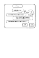
S2においてコインを投入した利用者は、まず、第一撮影空間R1に入場する。そして、課金処理部43によって、コインの投入の完了が判断されると、表示制御部101は、タッチパネル5aに「メニュー選択画面」を表示する(S80)。この「メニュー選択画面」とは、例えば図11に示すように、複数の演出手法が表示されていて、これら演出手法の中から利用者が所望の演出手法を選択するためのメニュー画面である。なお、選択は、カーソル移動によって行ってもよいし、所望の演出手法が表示されている部分に利用者がタッチすることによって行ってもよい。
A user who has inserted coins in S2 first enters the first shooting space R1. When the charging
ここで、利用者によって演出手法が選択されると(S81,YES)、選択された演出手法の撮影ポーズ例を示すポーズ例画像がタッチパネル5aに表示される(S84)。具体的には、メニュー決定部112が、利用者の選択する演出手法を示した演出手法選択信号を入力部72から検知し、この演出手法に対応する演出手法データを演出手法データ記憶部122より読み出す。そして、撮影ポーズ通知部120は、メニュー決定部112からの制御信号に基づいて、読み出された演出手法データに対応したポーズ例画像のデータを撮影ポーズ例記憶部111から読み出し、表示制御部113に送信する。そして、表示制御部113が、このポーズ例画像をタッチパネル5aに表示する。ここで、ポーズ例画像の例を図12(a)に示す。同図は、「フルーツの上に乗ってみよう」という演出手法を選択した場合のポーズ例画像である。
Here, when an effect method is selected by the user (S81, YES), a pose example image showing an example of a shooting pose of the selected effect method is displayed on the
なお、利用者が演出手法を選択しない場合であっても(S81,NO)、メニュー選択画面の表示から所定時間が経過すればタイムオーバーと判断され(S82,YES)、デフォルトとして設定されている演出手法が自動選択される(S83)。なお、タイムオーバーと判断されない場合、S80〜S81の処理が繰り返される(S82,NO)。 Even if the user does not select the effect method (S81, NO), it is determined that the time is over if a predetermined time has elapsed from the display of the menu selection screen (S82, YES), and the effect set as the default A method is automatically selected (S83). If it is not determined that the time is over, the processes of S80 to S81 are repeated (S82, NO).
そして、ポーズ例画像の表示(S84)から所定時間が経過すると、表示制御部113は、このポーズ例画像の表示を打ち切り、カメラユニット4aによって撮影されている動画(ライブビュー)をタッチパネル5aに表示する(S85)。また、表示制御部113は、上記ライブビューのみならず、撮影ボタンをタッチパネル5aに表示する(S85)。
When a predetermined time has elapsed from the display of the pose example image (S84), the
そして、利用者が写真撮影のタイミングで上記撮影ボタンに触れると(S86,YES)、S88において利用者の写真撮影が行われる。具体的には、利用者が上記撮影ボタンに触れると、タッチパネル5aの入力部72がタイミング識別信号を静止画像取得部114に送信する。そして、静止画像取得部114が、このタイミング識別信号によって上記写真撮影のタイミングを検出する。そして、静止画像取得部114は、このタイミングで表示制御部113が入力している動画のデータから静止画像を取得し、この静止画像のデータを静止画像記憶部68に保存する。なお、この静止画像の例を図12(b)に示す。図12(b)は、図12(a)のポーズ例画像に応じて撮影ポーズをとる利用者を撮影した静止画像である。
When the user touches the shooting button at the timing of taking a photograph (S86, YES), a photograph of the user is taken in S88. Specifically, when the user touches the shooting button, the
なお、利用者が上記撮影ボタンに触れない場合であっても(S86,NO)、ライブビューの表示開始から所定時間が経過するとタイムオーバーと判断され(S87,YES)、S88において自動的に写真撮影が行われる。なお、ライブビューの表示開始から所定時間が経過していない場合、S84〜S87が繰り返される。 Even when the user does not touch the shooting button (S86, NO), it is determined that the predetermined time has passed since the start of the live view display (S87, YES), and the photograph is automatically taken in S88. Is done. If a predetermined time has not elapsed since the start of live view display, S84 to S87 are repeated.
S88が終了すると、写真撮影により得られた静止画像からスタンプ画像を作成する処理を行う(S89)。このスタンプ画像の作成について説明すると以下のとおりである。 When S88 ends, processing for creating a stamp image from a still image obtained by photography is performed (S89). The creation of this stamp image will be described as follows.
まず、静止画像記憶部68に保存されている静止画像のデータがスタンプ画像加工部115によって読み出される。さらに、スタンプ画像加工部115は、メニュー決定部112からの制御信号に基づいて、上記静止画像を加工してスタンプ画像のデータを生成する。そして、表示制御部113は、このスタンプ画像のデータを読み込んで、スタンプ画像をタッチパネル5aに表示する。これにより、利用者に選択された演出手法に基づいてスタンプ画像を作成でき、利用者は作成されたスタンプ画像を確認することができる。
First, still image data stored in the still
さらに、ここで加工されたスタンプ画像に対し、利用者が落書き等の編集処理を施すようにしてもよい。具体的には、利用者がタッチペン6aを用いて編集処理を施すと、タッチパネル5aの入力部72は、利用者の編集指示を示した編集指示信号をスタンプ画像加工部115に送信する。そして、スタンプ画像加工部115は、この編集指示信号を検知すると、この加工指示信号に基づいてスタンプ画像に編集等を施す。
Further, the user may perform an editing process such as graffiti on the stamp image processed here. Specifically, when the user performs an editing process using the
ここで、作成されたスタンプ画像の例を図12(c)に示す。同図は、「フルーツの上に乗ってみよう」という演出手法を選択した場合に加工されたスタンプ画像である。さらに、図12(d)は、上記スタンプ画像に対して編集処理(落書き)を施したスタンプ画像である。 An example of the created stamp image is shown in FIG. This figure is a stamp image processed when the production method “Let's get on the fruit” is selected. Further, FIG. 12D is a stamp image obtained by performing editing processing (graffiti) on the stamp image.
さらに、以上のようにして加工されたスタンプ画像のデータは、スタンプ画像加工部115によってスタンプ画像記憶部69に保存される(S90)。その後、表示制御部113は、タッチパネル5aに終了ボタンを表示し、利用者がこの終了ボタンに触れると、スタンプ画像作成処理を終了する(S91,YES)。
Further, the stamp image data processed as described above is stored in the stamp
また、利用者がこの終了ボタンを押さない場合(S91,NO)、残り制限時間がゼロになるまで、S84〜S91の処理を繰り返すことができる(S92,NO)。これにより、利用者は、選択した演出手法に基づいたスタンプ画像を複数作成することができる。そして、残り制限時間がゼロと判断されると、スタンプ画像作成処理を終了する(S92,YES)。 If the user does not press the end button (S91, NO), the processes of S84 to S91 can be repeated until the remaining time limit becomes zero (S92, NO). Thereby, the user can create a plurality of stamp images based on the selected rendering technique. When it is determined that the remaining time limit is zero, the stamp image creation process is terminated (S92, YES).
スタンプ画像作成処理の終了が判断されると、選択画面生成部121は、スタンプ画像選択画面のデータを生成し、表示制御部118に送信する。これにより、スタンプ画像選択画面がタッチパネル5bに表示される(S93)。具体的には、選択画面生成部121が、スタンプ画像記憶部69に保存された全てのスタンプ画像のデータからスタンプ画像選択画面のデータを生成し、表示制御部118に送信することにより、スタンプ画像選択画面が表示される。
When it is determined that the stamp image creation process is finished, the selection screen generation unit 121 generates data of the stamp image selection screen and transmits the data to the
そして、利用者が、スタンプ画像選択画面に示されているスタンプ画像のうち、所望のスタンプ画像にタッチすると、利用者の指定するスタンプ画像が選択される(S94,YES)。具体的には、利用者が、タッチパネル5bに表示されている所望のスタンプ画像にタッチすると、タッチパネル5bの入力部74がスタンプ画像選択情報をスタンプ画像選択部116に送信する。そして、スタンプ画像選択部116は、このスタンプ画像選択情報の示すスタンプ画像のデータをスタンプ画像記憶部69から読み出し、表示制御部118に入力する。
When the user touches a desired stamp image among the stamp images displayed on the stamp image selection screen, the stamp image designated by the user is selected (S94, YES). Specifically, when the user touches a desired stamp image displayed on the
なお、利用者によってスタンプ画像の指定がない場合(S94,NO)、スタンプ画像選択画面の表示から所定時間が経過したか否かが判断され、所定時間を経過していない場合はS93〜S94が繰り返され(S95,NO)、所定時間を経過している場合はタイムオーバーと判断される(S95,YES)。この場合、S96においてスタンプ画像選択部116がスタンプ画像を自動選択する。なお、S96の処理の詳細は、実施の形態1におけるS26の処理と同様であるため、ここではその説明を省略する。
If the stamp image is not designated by the user (S94, NO), it is determined whether or not a predetermined time has elapsed from the display of the stamp image selection screen. If the predetermined time has not elapsed, S93 to S94 are performed. It is repeated (S95, NO), and when the predetermined time has elapsed, it is determined that the time is over (S95, YES). In this case, the stamp
スタンプ画像の選択が終了すると、S81において選択された演出手法の撮影ポーズ例を示すポーズ例画像がタッチパネル5bに表示される(S97)。具体的には、撮影ポーズ通知部120が、撮影ポーズ例記憶部111から読み出したポーズ例画像のデータを表示制御部118に送信する。そして、表示制御部118が、このポーズ例画像をタッチパネル5aに表示する。例えば、「自分の顔を手の上に乗せてみる?」という演出手法が選択されている場合、手のひらを上に向けたポーズ例の画像が表示される。
When the selection of the stamp image is completed, a pose example image showing an example of the shooting pose of the effect method selected in S81 is displayed on the
そして、ポーズ例画像の表示から所定時間が経過すると、表示制御部118は、スタンプ画像選択部116から入力したスタンプ画像を、カメラユニット4bから取得されている動画上に合成し、合成した動画(ライブビュー)をタッチパネル5bに表示させる(S98)。なお、ここで、表示制御部118は、撮影ボタンもタッチパネル5bに表示させる(S98)。
When a predetermined time has elapsed since the display of the pose example image, the
ここで、合成画像調整部117は、メニュー決定部112からの制御信号に基づいて、動画上に合成されるスタンプ画像の配置を調整する(S99)。これにより、利用者によって選択された画像演出メニューに従った動画をタッチパネル5bに表示することができる。
Here, the composite
例えば、選択された画像演出メニューが「フルーツの上に乗ってみよう!」の場合、図12(e)に示すように、カメラユニット4bに撮影されている動画における隅の領域に、フルーツの上に乗った被写体像を示すスタンプ画像が合成される。また、選択された画像演出メニューが「自分の顔を手の上に乗せてみる?」の場合、カメラユニット4bに撮影されている動画における被写体像(利用者像)の手を示す領域上にスタンプ画像が合成される。
For example, when the selected image effect menu is “Let's get on the fruit!”, As shown in FIG. 12 (e), the top of the fruit is placed in the corner area of the video shot by the
その後、利用者が写真撮影のタイミングで上記撮影ボタンに触れると(S100,YES)、S102において利用者の写真撮影が行われる。具体的には、利用者が上記撮影ボタンに触れると、タッチパネル5bの入力部74がタイミング識別信号を印刷用画像取得部119に送信する。そして、印刷用画像取得部119が、このタイミング識別信号によって上記写真撮影のタイミングを検出する。そして、印刷用画像取得部119は、表示制御部118がタッチパネル5bに表示している合成後の動画のデータから上記タイミングで静止画像を取得し、この静止画像のデータを印刷用画像記憶部70に保存する。
Thereafter, when the user touches the shooting button at the timing of taking a photograph (S100, YES), a photograph of the user is taken in S102. Specifically, when the user touches the shooting button, the
なお、利用者が上記撮影ボタンに触れない場合であっても(S100,NO)、撮影ボタンの表示(S98)から所定時間が経過するとタイムオーバーと判断され(S101,YES)、S102において自動的に写真撮影が行われる。なお、タイムオーバーと判断されない場合(S101,NO)、S100〜S101が繰り返される。 Even if the user does not touch the shooting button (S100, NO), it is determined that a predetermined time has elapsed from the display of the shooting button (S98) (S101, YES), and automatically in S102. A photo is taken. If it is not determined that the time is over (S101, NO), S100 to S101 are repeated.
その後、タッチパネル5bに終了ボタンが表示され、利用者がこの終了ボタンを押すと、合成撮影処理が終了する(S103,YES)。
Thereafter, an end button is displayed on the
また、利用者がこの終了ボタンを押さない場合(S103,NO)、残り制限時間がゼロか否かが判断され、ゼロでない場合、合成撮影処理を繰り返すことができる(S104,NO)。そして、残り制限時間がゼロと判断されると、合成撮影処理を終了する(S104,YES)。 If the user does not press the end button (S103, NO), it is determined whether or not the remaining time limit is zero. If it is not zero, the composite photographing process can be repeated (S104, NO). If it is determined that the remaining time limit is zero, the composite shooting process is terminated (S104, YES).
その後、印刷用画像記憶部70に保存されている印刷用画像のデータは、編集画像処理部51によって編集され(S5)、印刷制御部53が、この編集された印刷用画像のデータに基づいてプリンタ46を制御する。これにより、上記印刷用画像に基づいた画像をプリント紙48上に出力できる。ここで、プリント紙48上に印刷された画像の例を図12(f)に示す。図12は、同図は、「フルーツの上に乗ってみよう」という演出手法を選択した場合に印刷された画像であって、S5において編集処理が施されたものである。
Thereafter, the print image data stored in the print
以上のように、本実施の形態の写真プリント装置100によれば、表示制御部118は、カメラユニット4bに撮影されている動画上に、カメラユニット4aで撮影された静止画像に基づく画像を合成して表示している。ここで、合成画像調整部117が、メニュー決定部112からの制御信号に基づいて表示制御部118の合成表示動作を調整しているので、表示制御部118は、予め用意されている演出手法データに基づいた画像を表示していることになる。これにより、タッチパネル5bに合成表示される画像に特徴、個性を持たせることが可能となる。
As described above, according to the
また、本実施の形態の写真プリント装置100によれば、スタンプ画像加工部115は、予め用意されている演出手法データに従って、静止画像からスタンプ画像を加工している。これにより、カメラユニット4bに撮影されている動画に対して合成するスタンプ画像に特徴、個性を持たせることが可能となる。
Further, according to the
さらに、本実施の形態の写真プリント装置100によれば、撮影ポーズ通知部120が、読み出された演出手法データに応じた撮影ポーズを示したポーズ例画像を表示していることになる。したがって、利用者に対し、読み出された演出手法データの示す演出手法に応じた撮影ポーズを確実に認識させることができ、上記演出手法に沿わない撮影ポーズをとったまま写真撮影させることを抑制できる。
Furthermore, according to the
また、本実施の形態の写真プリント装置100によれば、メニュー決定部112が、演出手法データ記憶部122に格納されている複数の演出手法データのなかから、利用者の所望する演出手法を示す演出手法データを読み出している。したがって、表示制御部118によって合成表示される画像は、利用者の所望する演出手法に沿ったものとなる。
In addition, according to the
本発明は上述した各実施形態に限定されるものではなく、請求項に示した範囲で種々の変更が可能であり、異なる実施形態にそれぞれ開示された技術的手段を適宜組み合わせて得られる実施形態についても本発明の技術的範囲に含まれる。 The present invention is not limited to the above-described embodiments, and various modifications can be made within the scope of the claims, and embodiments obtained by appropriately combining technical means disclosed in different embodiments. Is also included in the technical scope of the present invention.
本発明は、利用者を撮影した画像をプリント媒体上に出力することの可能な写真プリント装置に利用できる。なお、この写真プリント装置は、例えば、ゲームセンター、遊園地等の遊戯場に配置されているものである。 INDUSTRIAL APPLICABILITY The present invention can be used for a photographic printing apparatus that can output an image taken by a user onto a print medium. In addition, this photo printing apparatus is arrange | positioned at amusement parks, such as a game center and an amusement park, for example.
4a カメラユニット(第一撮影手段、第二撮影手段)
4b カメラユニット(第二撮影手段)
5a タッチパネル(表示手段)
5b タッチパネル(表示手段)
6a タッチペン
6b タッチペン
41 制御装置(制御手段)
46 プリンタ(画像出力手段)
48 プリント紙(プリント媒体)
50 撮影画像処理部
51 編集画像処理部
52 記憶部
53 印刷制御部
61 表示制御部
62 静止画像取得部
63 スタンプ画像加工部(画像加工手段)
64 合成画像調整部
65 表示制御部(表示制御手段)
66 印刷用画像取得部
67 スタンプ画像選択部
68 静止画像記憶部
69 スタンプ画像記憶部
70 印刷用画像記憶部
71 表示部
72 入力部
73 表示部
74 入力部
75 選択画面生成部
100 写真プリント装置
101 表示制御部
102 静止画像取得部
103 スタンプ画像加工部(画像加工手段)
104 合成画像調整部
105 印刷用画像取得部
106 スタンプ画像選択部
107 モード切替部(モード切替手段)
108 選択画面生成部
111 撮影ポーズ例記憶部
112 メニュー決定部(演出手法決定手段)
113 表示制御部
114 静止画像取得部
115 スタンプ画像加工部(画像加工手段)
116 スタンプ画像選択部
117 合成画像調整部
118 表示制御部(表示制御手段)
119 印刷用画像取得部
120 撮影ポーズ通知部(撮影ポーズ通知手段)
121 選択画面生成部
122 演出手法データ記憶部(記憶手段)
R1 第一撮影空間(撮影スペース)
R2 第二撮影空間(撮影スペース)
4a Camera unit (first photographing means, second photographing means)
4b Camera unit (second photographing means)
5a Touch panel (display means)
5b Touch panel (display means)
46 Printer (Image output means)
48 Print paper (print media)
DESCRIPTION OF
64 Composite
66 Print
104 composite
108 Selection
113
116 Stamp
119 Print
121 Selection
R1 First shooting space (shooting space)
R2 Second shooting space (shooting space)
Claims (12)
上記制御手段は、
上記第二撮影手段で撮影されている動画をリアルタイムで上記表示手段に表示すると共に、上記第一撮影手段で撮影された静止画像に基づく画像を上記動画に合成して上記表示手段に表示する表示制御手段と、
上記第一撮影手段で撮影された静止画像を加工して出力する画像加工手段と、
合成後の画像の演出手法を定めた演出手法データを記憶手段から読み出す演出手法決定手段とを含み、
上記画像加工手段は、上記演出手法決定手段によって読み出された演出手法データに基づいて、上記静止画像を加工し、
上記表示制御手段は、上記画像加工手段が出力した画像を上記動画上に合成して上記表示手段に表示することを特徴とする写真プリント装置。 First and second photographing means for photographing a subject, display means for displaying an image, image output means for outputting an image on a print medium based on an image displayed on the display means, and operation of the apparatus A photographic printing apparatus comprising control means for controlling,
The control means includes
A display in which the moving image captured by the second imaging unit is displayed on the display unit in real time, and an image based on the still image captured by the first imaging unit is combined with the moving image and displayed on the display unit Control means ;
Image processing means for processing and outputting the still image captured by the first imaging means;
Effect method determining means for reading the effect method data defining the effect method of the image after synthesis from the storage means,
The image processing means processes the still image based on the effect method data read by the effect method determining means,
The photographic printing apparatus characterized in that the display control means synthesizes the image output from the image processing means on the moving image and displays it on the display means .
利用者からの要求に応じて、上記撮影用カメラを上記第一撮影手段として制御する第一のモードと、上記撮影用カメラを上記第二撮影手段として制御する第二のモードとを切替えるモード切替手段を含むことを特徴とする請求項4または5に記載の写真プリント装置。 The control means includes
Mode switching for switching between a first mode for controlling the photographing camera as the first photographing means and a second mode for controlling the photographing camera as the second photographing means in response to a request from the user. 6. The photo printing apparatus according to claim 4 , further comprising means.
上記演出手法決定手段によって読み出された演出手法データに応じた撮影ポーズをとるべきことを利用者に通知する撮影ポーズ通知手段を含む請求項1〜7のいずれか1項に記載の写真プリント装置。 The control means includes
8. The photo printing apparatus according to claim 1, further comprising a shooting pose notifying unit for notifying a user that a shooting pose should be taken according to the rendering method data read by the rendering method determining unit. .
上記演出手法決定手段は、利用者の所望する演出手法を特定する演出手法識別情報を入力手段から取得すると共に、この情報に対応する演出手法データを上記記憶手段から読み出すことを特徴とする請求項1〜8のいずれか1項に記載の写真プリント装置。 The storage means stores a plurality of effect method data,
The presentation method determining means acquires the presentation method identification information for specifying the presentation method desired by the user from the input means, and reads the presentation method data corresponding to the information from the storage means. The photographic printing apparatus according to any one of 1 to 8 .
上記制御手段が実行する手順に、
合成後の画像の演出手法を定めた演出手法データを記憶手段から読み出すステップと、
上記読み出された演出手法データに基づいて、上記第一撮影手段で撮影された静止画像を加工して出力するステップと、
上記第二撮影手段で撮影されている動画をリアルタイムで上記表示手段に表示すると共に、上記出力した画像を上記動画に合成して上記表示手段に表示するステップと、を含むことを特徴とする写真プリント装置の画像出力方法。 First and second photographing means for photographing a subject, display means for displaying an image, image output means for outputting an image on a print medium based on an image displayed on the display means, and operation of the apparatus An image output method of a photographic printing apparatus comprising a control means for controlling,
In the procedure executed by the control means,
A step of reading the production method data defining the production method of the combined image from the storage means;
Processing and outputting the still image captured by the first imaging means based on the read effect technique data;
Photos comprising and displays on the display means in real time video that is captured by the second imaging means, and displaying on the display means an image the output by combining the above video, the Image output method of printing apparatus.
Priority Applications (1)
| Application Number | Priority Date | Filing Date | Title |
|---|---|---|---|
| JP2004024773A JP4565263B2 (en) | 2004-01-30 | 2004-01-30 | Photo printing apparatus, image printing method for photo printing apparatus, control program for photo printing apparatus, and recording medium recording control program for photo printing apparatus |
Applications Claiming Priority (1)
| Application Number | Priority Date | Filing Date | Title |
|---|---|---|---|
| JP2004024773A JP4565263B2 (en) | 2004-01-30 | 2004-01-30 | Photo printing apparatus, image printing method for photo printing apparatus, control program for photo printing apparatus, and recording medium recording control program for photo printing apparatus |
Publications (2)
| Publication Number | Publication Date |
|---|---|
| JP2005217978A JP2005217978A (en) | 2005-08-11 |
| JP4565263B2 true JP4565263B2 (en) | 2010-10-20 |
Family
ID=34907359
Family Applications (1)
| Application Number | Title | Priority Date | Filing Date |
|---|---|---|---|
| JP2004024773A Expired - Fee Related JP4565263B2 (en) | 2004-01-30 | 2004-01-30 | Photo printing apparatus, image printing method for photo printing apparatus, control program for photo printing apparatus, and recording medium recording control program for photo printing apparatus |
Country Status (1)
| Country | Link |
|---|---|
| JP (1) | JP4565263B2 (en) |
Families Citing this family (8)
| Publication number | Priority date | Publication date | Assignee | Title |
|---|---|---|---|---|
| JP2007318671A (en) | 2006-05-29 | 2007-12-06 | Canon Inc | Image processing apparatus, recording apparatus, and image processing method |
| JP5013549B2 (en) * | 2009-12-16 | 2012-08-29 | 株式会社バンダイナムコゲームス | Program, information storage medium, photo printing apparatus and photo printing method |
| JP2012205114A (en) * | 2011-03-25 | 2012-10-22 | Casio Comput Co Ltd | Image processing device, image processing method, and program |
| JP2013131878A (en) | 2011-12-21 | 2013-07-04 | Sony Corp | Image processing device, image processing method, and program |
| JP6032378B1 (en) * | 2016-01-08 | 2016-11-30 | フリュー株式会社 | Photo creation game machine and image processing method |
| JP6601364B2 (en) * | 2016-10-21 | 2019-11-06 | フリュー株式会社 | Photo sticker creating apparatus and image processing method |
| JP6867587B2 (en) * | 2017-05-02 | 2021-04-28 | フリュー株式会社 | Photographing game consoles, information processing methods, and programs |
| JP6358380B1 (en) * | 2017-08-10 | 2018-07-18 | フリュー株式会社 | Photo sticker machine, photo sticker creation method, and photo sticker creation processing program |
Citations (1)
| Publication number | Priority date | Publication date | Assignee | Title |
|---|---|---|---|---|
| JP2001223876A (en) * | 2000-02-07 | 2001-08-17 | Fuji Photo Film Co Ltd | Image output device |
Family Cites Families (3)
| Publication number | Priority date | Publication date | Assignee | Title |
|---|---|---|---|---|
| JPH10117344A (en) * | 1996-10-08 | 1998-05-06 | Taito Corp | Synthesized amusement device for portrait and frame strip comic |
| JPH10308911A (en) * | 1997-05-07 | 1998-11-17 | Yamaha Corp | Photographed image printer |
| JPH11234602A (en) * | 1998-02-17 | 1999-08-27 | Namco Ltd | Video print supply device |
-
2004
- 2004-01-30 JP JP2004024773A patent/JP4565263B2/en not_active Expired - Fee Related
Patent Citations (1)
| Publication number | Priority date | Publication date | Assignee | Title |
|---|---|---|---|---|
| JP2001223876A (en) * | 2000-02-07 | 2001-08-17 | Fuji Photo Film Co Ltd | Image output device |
Also Published As
| Publication number | Publication date |
|---|---|
| JP2005217978A (en) | 2005-08-11 |
Similar Documents
| Publication | Publication Date | Title |
|---|---|---|
| JP5338805B2 (en) | Photo sticker creation apparatus and processing method | |
| JP7011206B2 (en) | Amusement photography equipment, image processing equipment, and image processing methods | |
| JP4453681B2 (en) | Photographic image processing apparatus, photographic image processing apparatus control method, photographic image processing control program, computer-readable recording medium, and composite image communication system | |
| JP4920175B2 (en) | PHOTOGRAPHIC PRINT DEVICE, PHOTOGRAPHIC PRINT DEVICE CONTROL METHOD, PHOTOGRAPHIC PRINT DEVICE CONTROL PROGRAM, AND COMPUTER READABLE RECORDING MEDIUM | |
| JP5515464B2 (en) | Image processing apparatus, photographing / editing apparatus, image processing method, image processing program, and recording medium storing the program | |
| JP4565263B2 (en) | Photo printing apparatus, image printing method for photo printing apparatus, control program for photo printing apparatus, and recording medium recording control program for photo printing apparatus | |
| JP5150783B1 (en) | Photo shooting system | |
| JP4742996B2 (en) | Image editing apparatus, image editing method, image editing program, recording medium recording the same, and photo printing apparatus | |
| JP2010166435A (en) | Photographed image edit device, mobile terminal, server, image transmission system, photographed image edit device control method, photographed image edit device control program, mobile terminal control program, server control program, and recording medium | |
| JP6085838B2 (en) | PHOTOGRAPHIC GAME DEVICE, IMAGE GENERATION METHOD, AND IMAGE GENERATION PROGRAM | |
| JP5540420B2 (en) | Photo sticker creation apparatus and processing method | |
| JP4218547B2 (en) | PHOTOGRAPHIC PRINT DEVICE, PHOTOGRAPHIC PRINT DEVICE CONTROL METHOD, PHOTOGRAPHIC PRINT DEVICE CONTROL PROGRAM, AND COMPUTER READABLE RECORDING MEDIUM | |
| JP4861370B2 (en) | Photography game system, photography game machine and server used therefor | |
| JP2004072404A (en) | Automatic photograph sticker vending machine and method, printing medium, and printing medium unit | |
| JP4990840B2 (en) | Image editing apparatus and photography game machine using the same | |
| JP3903870B2 (en) | PHOTO PRINT DEVICE CONTROL METHOD, PHOTO PRINT DEVICE CONTROL PROGRAM, RECORDING MEDIUM CONTAINING PHOTO PRINT DEVICE CONTROL PROGRAM, PHOTO PRINT DEVICE, AND PRINT MEDIUM UNIT | |
| JP6635170B2 (en) | Photo shooting game device, image processing method, and image processing program | |
| JP6083022B2 (en) | Photo shooting system | |
| JP4318564B2 (en) | Automatic photo creation device and automatic photo creation method | |
| JP3849572B2 (en) | Photography printing apparatus, photography printing apparatus control method, photography printing apparatus control program, computer-readable recording medium recording this program, and printing paper unit | |
| JP2014202962A (en) | Photographing game machine and control program thereof | |
| JP2003116096A (en) | Photographing device, photographing method, photographing program, recording medium recording the same, automatic photograph vending machine, printing medium, photograph providing method, photograph providing program and recording medium recording the same | |
| JP7534622B2 (en) | Image processing device and image processing method | |
| JP2006162719A (en) | Photographic sticker-vending machine and its method and program | |
| JP4556462B2 (en) | PHOTOGRAPHIC PRINTING DEVICE, PHOTOGRAPHIC PRINTING DEVICE CONTROL PROGRAM, COMPUTER-READABLE RECORDING MEDIUM, AND PHOTOGRAPHIC PRINTING DEVICE CONTROL METHOD |
Legal Events
| Date | Code | Title | Description |
|---|---|---|---|
| A072 | Dismissal of procedure [no reply to invitation to correct request for examination] |
Free format text: JAPANESE INTERMEDIATE CODE: A072 Effective date: 20050524 |
|
| A621 | Written request for application examination |
Free format text: JAPANESE INTERMEDIATE CODE: A621 Effective date: 20061110 |
|
| A711 | Notification of change in applicant |
Free format text: JAPANESE INTERMEDIATE CODE: A711 Effective date: 20070403 |
|
| RD02 | Notification of acceptance of power of attorney |
Free format text: JAPANESE INTERMEDIATE CODE: A7422 Effective date: 20070601 |
|
| A977 | Report on retrieval |
Free format text: JAPANESE INTERMEDIATE CODE: A971007 Effective date: 20090727 |
|
| A131 | Notification of reasons for refusal |
Free format text: JAPANESE INTERMEDIATE CODE: A131 Effective date: 20090915 |
|
| A521 | Request for written amendment filed |
Free format text: JAPANESE INTERMEDIATE CODE: A523 Effective date: 20091113 |
|
| TRDD | Decision of grant or rejection written | ||
| A01 | Written decision to grant a patent or to grant a registration (utility model) |
Free format text: JAPANESE INTERMEDIATE CODE: A01 Effective date: 20100706 |
|
| A01 | Written decision to grant a patent or to grant a registration (utility model) |
Free format text: JAPANESE INTERMEDIATE CODE: A01 |
|
| A61 | First payment of annual fees (during grant procedure) |
Free format text: JAPANESE INTERMEDIATE CODE: A61 Effective date: 20100719 |
|
| R150 | Certificate of patent or registration of utility model |
Free format text: JAPANESE INTERMEDIATE CODE: R150 Ref document number: 4565263 Country of ref document: JP Free format text: JAPANESE INTERMEDIATE CODE: R150 |
|
| FPAY | Renewal fee payment (event date is renewal date of database) |
Free format text: PAYMENT UNTIL: 20130813 Year of fee payment: 3 |
|
| R250 | Receipt of annual fees |
Free format text: JAPANESE INTERMEDIATE CODE: R250 |
|
| R250 | Receipt of annual fees |
Free format text: JAPANESE INTERMEDIATE CODE: R250 |
|
| R250 | Receipt of annual fees |
Free format text: JAPANESE INTERMEDIATE CODE: R250 |
|
| R250 | Receipt of annual fees |
Free format text: JAPANESE INTERMEDIATE CODE: R250 |
|
| R250 | Receipt of annual fees |
Free format text: JAPANESE INTERMEDIATE CODE: R250 |
|
| R250 | Receipt of annual fees |
Free format text: JAPANESE INTERMEDIATE CODE: R250 |
|
| LAPS | Cancellation because of no payment of annual fees |