JP4564717B2 - Hyperbolic electrical contact member - Google Patents
Hyperbolic electrical contact member Download PDFInfo
- Publication number
- JP4564717B2 JP4564717B2 JP2003047807A JP2003047807A JP4564717B2 JP 4564717 B2 JP4564717 B2 JP 4564717B2 JP 2003047807 A JP2003047807 A JP 2003047807A JP 2003047807 A JP2003047807 A JP 2003047807A JP 4564717 B2 JP4564717 B2 JP 4564717B2
- Authority
- JP
- Japan
- Prior art keywords
- tubular body
- contact socket
- wire
- suffix
- main shaft
- Prior art date
- Legal status (The legal status is an assumption and is not a legal conclusion. Google has not performed a legal analysis and makes no representation as to the accuracy of the status listed.)
- Expired - Lifetime
Links
- 230000013011 mating Effects 0.000 claims abstract description 18
- 239000004020 conductor Substances 0.000 claims abstract description 8
- 238000000034 method Methods 0.000 claims description 26
- 230000008569 process Effects 0.000 claims description 7
- 238000003466 welding Methods 0.000 claims description 7
- 238000003780 insertion Methods 0.000 claims description 6
- 230000037431 insertion Effects 0.000 claims description 6
- 229910000679 solder Inorganic materials 0.000 claims description 5
- 229910000881 Cu alloy Inorganic materials 0.000 claims description 4
- 238000004519 manufacturing process Methods 0.000 abstract description 11
- 238000002788 crimping Methods 0.000 abstract description 8
- 239000002184 metal Substances 0.000 abstract description 5
- 229910052751 metal Inorganic materials 0.000 abstract description 5
- 238000005096 rolling process Methods 0.000 abstract 1
- 230000014759 maintenance of location Effects 0.000 description 3
- 230000002093 peripheral effect Effects 0.000 description 3
- 238000013459 approach Methods 0.000 description 2
- 230000008901 benefit Effects 0.000 description 2
- 239000000463 material Substances 0.000 description 2
- 230000009467 reduction Effects 0.000 description 2
- 238000004873 anchoring Methods 0.000 description 1
- 238000005219 brazing Methods 0.000 description 1
- 230000002596 correlated effect Effects 0.000 description 1
- 238000005516 engineering process Methods 0.000 description 1
- 238000000605 extraction Methods 0.000 description 1
- 238000009434 installation Methods 0.000 description 1
- 239000012774 insulation material Substances 0.000 description 1
- 238000012986 modification Methods 0.000 description 1
- 230000004048 modification Effects 0.000 description 1
- 238000007747 plating Methods 0.000 description 1
- 238000003825 pressing Methods 0.000 description 1
- 238000012545 processing Methods 0.000 description 1
- 230000008439 repair process Effects 0.000 description 1
- 230000000717 retained effect Effects 0.000 description 1
Images


Classifications
-
- H—ELECTRICITY
- H01—ELECTRIC ELEMENTS
- H01R—ELECTRICALLY-CONDUCTIVE CONNECTIONS; STRUCTURAL ASSOCIATIONS OF A PLURALITY OF MUTUALLY-INSULATED ELECTRICAL CONNECTING ELEMENTS; COUPLING DEVICES; CURRENT COLLECTORS
- H01R13/00—Details of coupling devices of the kinds covered by groups H01R12/70 or H01R24/00 - H01R33/00
- H01R13/02—Contact members
- H01R13/15—Pins, blades or sockets having separate spring member for producing or increasing contact pressure
- H01R13/187—Pins, blades or sockets having separate spring member for producing or increasing contact pressure with spring member in the socket
-
- H—ELECTRICITY
- H01—ELECTRIC ELEMENTS
- H01R—ELECTRICALLY-CONDUCTIVE CONNECTIONS; STRUCTURAL ASSOCIATIONS OF A PLURALITY OF MUTUALLY-INSULATED ELECTRICAL CONNECTING ELEMENTS; COUPLING DEVICES; CURRENT COLLECTORS
- H01R13/00—Details of coupling devices of the kinds covered by groups H01R12/70 or H01R24/00 - H01R33/00
- H01R13/02—Contact members
- H01R13/10—Sockets for co-operation with pins or blades
- H01R13/11—Resilient sockets
- H01R13/111—Resilient sockets co-operating with pins having a circular transverse section
-
- Y—GENERAL TAGGING OF NEW TECHNOLOGICAL DEVELOPMENTS; GENERAL TAGGING OF CROSS-SECTIONAL TECHNOLOGIES SPANNING OVER SEVERAL SECTIONS OF THE IPC; TECHNICAL SUBJECTS COVERED BY FORMER USPC CROSS-REFERENCE ART COLLECTIONS [XRACs] AND DIGESTS
- Y10—TECHNICAL SUBJECTS COVERED BY FORMER USPC
- Y10T—TECHNICAL SUBJECTS COVERED BY FORMER US CLASSIFICATION
- Y10T29/00—Metal working
- Y10T29/49—Method of mechanical manufacture
- Y10T29/49002—Electrical device making
- Y10T29/49117—Conductor or circuit manufacturing
- Y10T29/49124—On flat or curved insulated base, e.g., printed circuit, etc.
- Y10T29/4913—Assembling to base an electrical component, e.g., capacitor, etc.
- Y10T29/49139—Assembling to base an electrical component, e.g., capacitor, etc. by inserting component lead or terminal into base aperture
-
- Y—GENERAL TAGGING OF NEW TECHNOLOGICAL DEVELOPMENTS; GENERAL TAGGING OF CROSS-SECTIONAL TECHNOLOGIES SPANNING OVER SEVERAL SECTIONS OF THE IPC; TECHNICAL SUBJECTS COVERED BY FORMER USPC CROSS-REFERENCE ART COLLECTIONS [XRACs] AND DIGESTS
- Y10—TECHNICAL SUBJECTS COVERED BY FORMER USPC
- Y10T—TECHNICAL SUBJECTS COVERED BY FORMER US CLASSIFICATION
- Y10T29/00—Metal working
- Y10T29/49—Method of mechanical manufacture
- Y10T29/49002—Electrical device making
- Y10T29/49117—Conductor or circuit manufacturing
- Y10T29/49204—Contact or terminal manufacturing
- Y10T29/49208—Contact or terminal manufacturing by assembling plural parts
-
- Y—GENERAL TAGGING OF NEW TECHNOLOGICAL DEVELOPMENTS; GENERAL TAGGING OF CROSS-SECTIONAL TECHNOLOGIES SPANNING OVER SEVERAL SECTIONS OF THE IPC; TECHNICAL SUBJECTS COVERED BY FORMER USPC CROSS-REFERENCE ART COLLECTIONS [XRACs] AND DIGESTS
- Y10—TECHNICAL SUBJECTS COVERED BY FORMER USPC
- Y10T—TECHNICAL SUBJECTS COVERED BY FORMER US CLASSIFICATION
- Y10T29/00—Metal working
- Y10T29/53—Means to assemble or disassemble
- Y10T29/5313—Means to assemble electrical device
- Y10T29/532—Conductor
- Y10T29/53209—Terminal or connector
Landscapes
- Connections Effected By Soldering, Adhesion, Or Permanent Deformation (AREA)
- Coupling Device And Connection With Printed Circuit (AREA)
- Details Of Resistors (AREA)
- Contacts (AREA)
- Thermistors And Varistors (AREA)
Abstract
Description
【0001】
本出願は、ここに参照として組み込まれた2002年2月28日に出願された発明の名称がHYPERBOLOID ELECTRICAL CONTACTの米国特許出願10/084,877の一部継続出願である。
【0002】
【発明の属する技術分野】
本発明は、自動高速生産工程を使用するコスト効率的な手法で製造でき、ユーザの要求に望ましいものとして異なる型の接尾が接触ソケットに取り付けできる、双曲面の接触ソケットに関する。
【0003】
【従来の技術】
双曲面の電気的な接触部材又は接触ソケットは、それらの信頼度、振動に対する抵抗、低い挿入力、低い電気抵抗、及び挿入/抽出の高回転数において周知である。従来の双曲面の接触ソケットは、両端で開口し、外殻を形成する2つの円筒状の部分内で同軸である、内部の管状のスリーブを有する。外側部分の一末端は、接合又はクリンプにより接触部材に永久にワイヤーを取り付ける穴を形成するために機械加工される。代替として、末端は接合されるか又は回路ボードに押圧されるピンを形成するために機械加工できるか、或いはピンにおいて接触部材を包むことによってワイヤーを取り付けするために使用できる。第二の外部の円筒状の部分の中心に近い方の端は嵌合コネクター又は装置の雄ピンを受け取るために開口している。複数のルーズワイヤー又は移動性ワイヤーは、単一シートの双曲面型を形成するために内部のスリーブ内に配置される。内部スリーブの各端で、ワイヤーは内部スリーブと外部スリーブとの間で軸方向に戻るように外部方向に180度曲げられる。それによって、ワイヤー端は、図1の従来技術に示されるように、ワイヤーと内外スリーブとの間で押圧手段により内部スリーブの各端で保持される。機械的で伝導性の取り付けを提供する、回転、クリンプ、変形、又は他の適切な手段のある形式は、内部スリーブの軸の中間点で、又はかかる中間点の近くに外部スリーブを取り付けするために使用される。この接触部材の形状は従来使用されており、困難な組立作業を示し、かつ高コストで、高い正確性で構成部分を機械加工することを要求することが周知である。加えて、ワイヤーの押圧保持の性質により、特に接触部材の使用中に、ワイヤーが、内部スリーブ及び外部スリーブ内から分離されるようになることは一般的であり、それによって、接触部材が使用されている装置の部分の不良に結びつく。加えて、かかるタイプの部分の不良は、嵌合する雄コネクタ要素の損傷を導き、さらに接触部材が配置された全システムの修理範囲とコストを悪化させる。加えて、内部と外部の円筒状部分並びに保持された接触ワイヤーの同心状配置のために、接触構造は他の形状の接触部材よりも大きい直径であり、したがって、より接触密度の高い適用には使用できないか、又は小型化が実現される、上に述べられた特性を要求する適用には使用できない。数多の従来からの構成の実施例がある(例えば、特許文献1,2,3及び4参照。)。
【0004】
より接近する中心距離間隔を必要とする適用での使用を可能にするために、より小さな外径の双曲面の接触ソケットを提供することは有用だろう。不必要な部分の除去によって、及び双曲面の接触域を形成する接触本体内の位置へ接触ワイヤーの永久的で伝導性な取り付けによる組立の効率的な改良によって製造コストを縮小することはさらに有用だろう。異なる接尾型に続いて容易に取り付けることが可能な、特定の接尾型とは別に個別に組み立てることができる接触ソケットを提供することはさらに有用だろう。高コストな機械加工された構成部分の必要性が薄れるか又は無くなる、接触ソケットを提供することはさらに有用だろう。
【0005】
【特許文献1】
米国特許第3,107,966号明細書
【特許文献2】
米国特許第3,229,356号明細書
【特許文献3】
米国特許第3,470,527号明細書
【特許文献4】
米国特許第6,102,746号明細書
【発明が解決しようとする課題】
本発明の目的は、自動高速生産工程を使用するコスト効率的な手法で製造でき、ユーザの要求に望ましいものとして異なる型の接尾が接触ソケットに取り付けできる、双曲面の接触ソケットを提供することである。
【0006】
【課題を解決するための手段】
接触ソケットは、嵌合ピンの末端を受取るための入り口部を定義する、一方の端のリップと、回路ボード又は他の装置に取り付けるために意図される形状の接尾を反対端に有する、金属又は他の適切な伝導性物質の管状本体を有する。管状本体は、本体の外部端及び内部端の、又はかかる端の近くのそれぞれの内部表面に対するそれぞれの端に溶接されるか、或いは伝導的で永久的に固着され、単一シートの双曲面の型を形成する角度で配置した、複数の伝導性ワイヤーを含む。
かかる本体は、好ましくは、従来の設計によって通常要求される、正確な機械加工部分よりも安価である、絞り加工によって製造される。好ましくは、ワイヤーは管状本体内でレーザー溶接され、管状本体の内側に永久的に直接取り付けされる。従来の双曲面の接触部材のような接触ワイヤーを固定するために、追加的なスリーブ又は管は必要ではない。したがって、新規の接触ソケットは、与えられた現在の格付けにおいて従来の双曲面の接触部材の直径よりも実質的に小さい直径を有し、短縮した直径はコネクタ、回路ボード、装置又は他の装置で使用するためにさらに密に包まれる新規な接触ソケットを可能にする。
【0007】
接触ソケットの組み立て工程は、高速自動設備によって実行でき、管状本体内の接触ワイヤーの一貫した取り付けを保証する。接尾端から分離して組み立て可能なワイヤー接触アセンブリとして表示されたサブアセンブリである、溶接されたか、又は伝導的で永久的に取り付けられたワイヤーを有することは新規な接触ソケットの利点である。結果として、同一のワイヤー接触アセンブリは、使用される要求に適するために様々な接尾型に続いて付けられる。典型的な接尾型は、クリンプ、ハンダ・カップ、ピン又は表面実装でありうる。かかる形状によって容認されるように、好ましくは、接尾端は、従来の設計によって一般的に必要とされる正確な機械加工された部品よりも安価である、絞り加工によって製造される。
【0008】
本発明の一の実施態様において、接触ソケットの組立てにおいて管状本体内のワイヤーを適応させるために使用された主軸は、接触ワイヤーの組立後における管状本体への取り付けを維持し、様々な接尾が取り付けできる接続ピンとして役立つ。本発明のかかる態様は、好ましくは、回転、クリンプ、変形、又は他の適切な手段による本体の変形によって管状本体と主軸に対するワイヤーの伝導性で永久的な取り付けを提供する。
【0009】
本発明は、図を参照して下記において、さらに詳細に記載される。
【0010】
【発明の実施の形態】
図2及び3を参照するに、嵌合ピンの末端を受取るための入り口部14を定義する、リップ12と、回路ボード又は他の部分に取り付けるための接尾16を有する、適切な金属又は他の伝導性物質の管状本体10を有する、本発明と一致する接触ソケットが示されている。管状本体は、本体の外部端及び内部端に対するそれぞれの端に溶接されるか、又は伝導性で永久的に固着され、双曲面の型を形成するために縦軸に対する角度位で配置した、複数の伝導性ワイヤー18を有する。例示された実施態様において、本体10は、回転、クリンプ、変形、又は機械的で伝導性の固着を提供する他の適切な手段によって接合部17で接尾16に取り付けられる。
【0011】
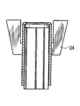
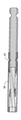
接触ソケットの製造方法は、図4乃至9と共に記載されるだろう。図4は、好ましくリップ12を有する管状本体10を示している。図5において、主軸の周囲に関して等置された溝22を受け取る縦のワイヤーを備えた主軸20が示されている。本体10は、図6に示されるように、グリッパーあご24で保持され、主軸20上に位置している。ワイヤー18は、それぞれの溝22において、リップ12の内部の環状曲面に関するワイヤーの外部端の位置に対して挿入される。
図7を参照するに、ワイヤーの上部端は、好ましくはレーザー溶接又は他の適切な手段によって、外部端の位置で本体にワイヤー端を固定するようにリップ12に隣接する管状本体の向かい合う内壁部分に伝導性で永久的に固着される。レーザー溶接部は、意図した位置で溶接部を提供するために本体の外部の端に関して位置している、1つ以上の溶接ヘッド28からのエネルギーによって提供される。
【0012】
主軸と管状本体は異なる方向へ互いに相関して移動できることが認識されるだろう。主軸は固定され、本体は主軸に関して移動可能である。代替として、管状本体が固定され、主軸はかかる本体に対して移動可能である。或いは、主軸と本体はお互いに関して移動可能であるかもしれない。相対的な移動の様々な形状は、採用される特定の組立機械によって決定される。
【0013】
ワイヤー18の上部端を伝導性で永久的に固着した後、本体と主軸は、図8に示されるように管状本体の内部端でワイヤーの下部端の位置に対してお互いに相関して移動される。本体と主軸は、図9に示されるように、ワイヤー18の角度配位を生じる所定の角度範囲によってお互いに関して回転される。ワイヤーの下部端は、好ましくは、レーザー溶接又は他の適切な手段によって管状本体の向かい合う壁部分に伝導性で永久的に固着され、本体と主軸はその後分離される。角度をなして配置されたワイヤーを有する、最終品としての本体は、接触ソケットに挿入される末端ピンとの電気的な結合を収容し提供する双曲面の型を形成する。
【0014】
本体10に対して溶接されるか、或いは伝導性で永久的に固着される双曲面の接触部材を備える本体10は、機械的で伝導性の取り付けを提供する、回転、クリンプ、変形、又は他の適切な手段などの適切な技術によって接尾16に機械的で電気的に取り付けられる。接尾は、特定の要求に適合するために様々なタイプとなりうる。例えば、接尾は図2に示すようにハンダ・カップ型であり、図10に示すようにクリンプ型であり、図11に示すようにピンの末端であり、図12に示すように表面実装パッドであるかもしれない。接尾は、代替的な構造で本体と完全に形成されるかもしれない。
【0015】
接触ソケットは、通常、ハウジング又は容器内に接触ソケットを固定するための一つ以上の保持要素を有する。図13及び14に例示される実施態様において、保持要素は、関連するハウジングに接触ソケットを配位して留める翼又は外に向かった角度のタブ30の形状である。タブは本体10に不可欠でありうるか、又は本体に固着された個別の要素でありうる。保持要素は、本来周知のように、バーブ又は肋材などの別の形態でありうる。
【0016】
上に記載の実施態様において、管状本体10は、接触ソケットへの挿入中に嵌合ピンを受取り、導くための入り口部を定義するリップ12を有する。リップはまた、接触ソケットへの嵌合ピンの挿入中において、ワイヤー18の向き合う端の損傷を防ぐために有利である。代替となる実施態様において、図15に示されるようにリップは削除される。
【0017】
新規の接触ソケットは、電気技術で周知の様々な物質から組み立て可能である。例えば、管状本体は金めっきした銅合金であり、さらに伝導性ワイヤーも金めっきした銅合金でありうる。物質のめっきの有無は、特定のユーザの要求と規格に依存して採用される。
【0018】
本発明による接触ソケットは、周知の技術において重要な利点を提供する。接触ワイヤーは、管状の接触本体の内側に直接的に、伝導性で永久的に固着されて、従来の双曲面の接触部材のように接触ワイヤーを固定するために追加的なスリーブ又は管は必要としない。したがって、新規の接触ソケットは、与えられた現在の格付けにおいて従来の双曲面の接触部材の直径よりも実質的に短い直径を有する。直径の短縮は、電子組立品の小型化が非常に望ましい、コネクタ、回路ボード又は他の要素の絶縁物質内に接触ソケットを位置付けるために必要な中心距離を短縮する。
【0019】
接触ソケットの本体は、従来の設計によって必要とされる正確に機械加工された部分よりも安価である、絞り加工によって製造できる。新規の接触ソケットはまた、従来の双曲面の接触部材が取り除かれた構造に不可欠である、2つの180度反転して曲がったように、かかるソケットの組み立てにおいて少数のワイヤーを使用する。かかる理由において、また追加的なスリーブ又は管の除去により、新規の接触ソケットは従来の双曲面のソケットよりも低コストで組み立て可能である。
【0020】
従来の双曲面のソケットにおけるような、かかるソケットの最終組立中において、ルーズワイヤーか、又は移動性ワイヤーの取り付けに依存しない、レーザー溶接を用いる組立技術は、接触ワイヤーの一貫した取り付けと信頼できる丈夫な製品を保証する、大容量自動化製造工程において適切である。かかる要因は製造時における高い生産性に寄与し、さらに製造の低コスト化に寄与する。
【0021】
新規の接触ソケットが、ワイヤー接触アセンブリと呼ばれる、溶接されたか、又は伝導性で永久的に固着されたワイヤーを有する本体に対して個別に組み立てられて取り付けられる接尾を有する。このようにして、同一のワイヤー接触アセンブリは、棚卸しと製造要求を簡素化し、コストを減少する、様々な接尾型に取り付けできる。
【0022】
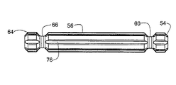
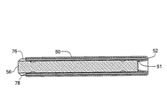
本発明の好ましい実施態様は、図16から始まって例示され、ここで主軸は接触ワイヤーの組立中に採用され、取り付けできる様々な接尾に組み立てられた接触ソケットを部分的に保持する。図16乃至18を参照するに、適切な金属又は別の伝導性物質の管状本体50は、嵌合ピンの末端を受取るための入り口部を定義する反転した構成52の外部端を有する。管状本体50のもう一方の端53は、主軸の合致端に対して管状本体の機械的で伝導性の取り付けを提供するように、回転、クリンプ、変形、又は他の適切な手段によって接合部58で主軸56の一方の端54に取り付けられる。管状本体に取り付け可能である、主軸端54は、管状本体の向かい合う部分がクリンプされるか、或いは固定される、周辺の溝60を有する。管状本体50は、管状本体の反転した端52の環状の陥凹51の一端と、及び管状本体及び嵌合する主軸端との間のもう一方の端において、伝導性で永久的に固着された、複数の伝導性ワイヤー62を有する。ワイヤーは、上に記載のように双曲面型を形成するように縦軸に対する角度で位置される。主軸の外部端64は、回転、クリンプ、変形、又は他の適切な手段によって主軸端64に機械的で伝導性の取り付けが可能な合致端70を有する、接尾68を受けるように形成される。接尾の向き合う部分は、接合部65で主軸の周辺の溝66にクリンプされるか、或いは固定される。図22に示される保持リング又はクリップ72は主軸56に配置され、一つ以上の外側に向かう翼又はタブ74を有するクリップは、関連するハウジングへ接触ソケットを適応させてロックすることができる。接尾68の外部端は、特定の要求に適合するために様々な型となりうる。例えば、接尾は図16に示されるようなハンダ・カップであり、図19に示されるようにクリンプ型であり、図20に示されるようにピンの末端であり、或いは図21に示されるように表面実装パッドであるかもしれない。
【0023】
図18で示される最良の形態として、主軸56は、主軸の長さに対する縦方向に沿って形成された複数の溝又は通路76を有する。例示された実施態様において、6つの溝又は通路は、主軸周辺に関して等置された主軸に提供される。伝導性ワイヤーは、下記にさらに記載されるように、接触ソケットの組立中にそれぞれの各溝76に位置される。
【0024】
図16の好ましい実施態様の接触ソケットの製造方法は、図17乃至28と共に記載される。図17は、反転した端52と管状の反対の端53を有する管状本体50を示している。図18は主軸の周辺に関して等置された、縦方向のワイヤーを受ける溝76を備える主軸を示す。主軸は、主軸にそれぞれ形成された周辺の溝60、66を各々有する、第一端54及び第二端64を有する。図6に関して既に記載された手法と同様に、本体50はグリッパーあごによって保持され、主軸上に位置される。図23に示されるように、ワイヤー78は、ワイヤーの外部端が反転した端52の内部の環状の陥凹51に接する位置に対する主軸56のそれぞれの溝76に挿入される。反転した端は、図24A及び24Bに示されるように、ワイヤーを機械的で電気的に固定するために適所にかしめされるか、クリンプされるか、又は適切に処理する。かかる実施態様において、反転した端は、ワイヤー間の領域に管の端部分を変形するように内部にかしめされるか、クリンプされるか、或いは適切に処理する。かしめか、クリンプか、又は適切な処理は、反転した端の内部から反転した端の外部に向かう、力を外に適用する、拡張穿孔鋏などの適切なツールによって達成される。
【0025】
次ぎに、本体50と主軸56は、図25に示されるように管状本体の反対の端で主軸の位置を決めるためにお互いに相関して移動され、本体と主軸はワイヤー78の角度配位を生じるために所定の角度範囲によってお互いに相関して回転される。ワイヤー78の端は、管状本体の向き合う部分と周辺の溝66の領域の主軸との間に伝導性で永久的に固着される。図26に示されるように、本体50は、管状本体に主軸端を固定するため、双曲面の接触部材型にワイヤーを固定するために接合部67で主軸の溝66にかしめされるか、クリンプされるか、或いは固定される。
【0026】
上に記載のように、主軸と管状本体は、組立工程中に異なる方向にお互いに相関して移動できる。例えば、主軸は固定され、本体は固定された主軸に関して移動可能である。或いは、管状本体は固定され、主軸は固定された管状本体において移動可能である。さらなる代替として、主軸と本体の両者は、お互いが移動可能な関係であるかもしれない。相関する移動のかかる様々な形態は、採用される特定の組立機械によって決定される。
【0027】
図16に示される実施態様において溶接が必要とされないことが認識されるだろう。ワイヤーは管状本体に機械的に接続される。このようにして、取り付けられた主軸を備える接触ソケットは一つの形態で組み立て可能であり、さらに様々な接尾はユーザの要求に適合するように主軸の合致端に取り付けられる。接尾が個別に組み立て可能で、取り付けられた主軸を備える接触ソケットに必要とされるように取り付けられるために、異なる接尾を有する様々な異なる接触ソケットを組み立てる必要性は存在しない。かかる手法において、主軸は、組立ツールとしての役割、及び組み立てられた接触ソケットの接続部分としての役割をする。
さらに、主軸は、主軸の外部端が様々な型の接尾に取り付け可能である、接尾の組立段階の一部である。接尾は上に例示された様々な型であるか、又は接尾は特定のユーザの適用に適合するために別の型となりうる。
【0028】
上に記載の実施態様のように、接触ソケットは、ハウジング又は容器に接触ソケットを固定するための一つ以上の保持機能か、又は装置を有する。図22に示されるように、保持機能又は装置は、一つ以上の外部に向かった角度のタブ74か、又は関連するハウジング若しくは容器に接触ソケットを適応させてロックすることができる、別の保持要素を有する保持リング又はクリップ72の形態になりうる。保持要素はバーブ又は肋材などの様々な別の形態となることが可能で、個別の支持構造に提供でき、又は例示のように本体50に不可欠である。
【0029】
図27A乃至27Dに示される、代替となる実施態様において、管状本体の反転した端は、反転した端の外側から反転した端の内側に向かい、内側に力を適用する適切なツールによって接合部69において外部でかしめされるか、クリンプされるか、又は固定される。
【0030】
図16に示される型の実施態様のさらなる代替となる実行として、伝導性ワイヤーは、本体との伝導性の接触部材で存続するが、特に高い電流における接触部材の使用中に、ワイヤーが加熱される場合に発生可能な熱膨張を適合するのに縦方向に移動可能であるように、図28A及び28Bに示されるように管状本体の反転した端でかしめできるか、クリンプされるか、又は固定される。
【0031】
管状本体の反対端のワイヤーは、本体と主軸を備える伝導性の接触部材で実質的に固定されるために上に記載のようにかしめされるか、クリンプされるか、又は固定される。代替として、管状本体の両端における伝導性ワイヤーは、本体を備える伝導性の接触部材で維持されるが、熱膨張を適合する縦軸方向に移動可能であるようにかしめされるか、クリンプされるか、又は固定されうる。
【0032】
特定の規格又は性能の要求に適合するような目的において、伝導性ワイヤーは、ここに記載された初期の実施態様のように管状本体の一端又は両端で溶接できる。
【0033】
本発明はここに特定に示されて記載されたものに限定されないが、様々な代替と修正は本発明の趣旨と範囲を逸脱しない限り当業者においてなされるだろう。
【図面の簡単な説明】
【図1】従来の双曲面の接触ソケットの切断図である。
【図2】本発明と一致する接触ソケットの実施態様の切断図である。
【図3】図2の接触ソケットの末端図である。
【図4】図2の実施態様で使用される管状本体の実施態様の切断図である。
【図5】図2の新規の接触ソケットの組み立てに利用できる主軸の側面図である。
【図6】管状本体内に挿入された主軸の切断図である。
【図7】管状本体の一方の端で伝導ワイヤーの位置を例示する切断側面図である。
【図8】管状本体の反対の端で伝導ワイヤーの位置を例示する切断側面図である。
【図9】伝導ワイヤーの角度の配位を例示する切断側面図である。
【図10】クリンプの接尾を例示する切断側面図である。
【図11】ピンの接尾を例示する切断側面図である。
【図12】表面実装パッドの接尾を例示する切断側面図である。
【図13】実装タブを例示する切断側面図である。
【図14】図13の実施態様の末端図である。
【図15】本発明と一致する接触ソケットの代替となる実施態様を例示する図である。
【図16】本発明と一致する接触ソケットの好ましい実施態様の切断図である。
【図17】図16の実施態様で使用される管状本体の好ましい実施態様の切断図である。
【図18】図16の実施態様で使用される主軸の好ましい実施態様の側面図である。
【図19】図16の実施態様のクリンプの接尾を例示する切断図である。
【図20】図16の実施態様のピンの接尾を例示する切断図である。
【図21】図16の実施態様の表面実装パッドの接尾を例示する切断図である。
【図22】図16の実施態様で使用される保持クリップの絵画図である。
【図23】管状本体内に挿入された主軸と伝導性ワイヤーの切断図である。
【図24A】管状本体の反転した端の内部の様相の変形による反転した端内に固定されたワイヤーを例示する、管状本体の主軸と伝導性ワイヤーの切断図である。
【図24B】図24Aの部分的な末端図である。
【図25】管状本体に固定される位置における主軸の切断図である。
【図26】主軸に固定された管状本体を例示する切断図である。
【図27A】管状本体の反転した端の外部の様相の変形を例示する、管状本体と主軸の側面図である。
【図27B】ワイヤーが管状本体の反転した端内に固定された、管状本体内の主軸と伝導性ワイヤーの切断図である。
【図27C】図27Aの部分的な末端図である。
【図27D】主軸に固定された管状本体を例示する切断図である。
【図28A】縦に移動可能な伝導性のワイヤーを提供する管状本体の反転した端の変形を例示する、切断図である。
【図28B】図28Aの部分的な末端図である。
【符号の説明】
10 管状本体
12 リップ
14 入り口部
16 接尾
17 接合部
18 伝導性ワイヤー
20 主軸
22 溝
24 グリッパーあご
28 溶接ヘッド
30 タブ
50 管状本体
51 環状の陥凹
52 反転した構成
53 一端
54 一方の端
56 主軸
58 接合部
60 溝
62 伝導性ワイヤー
64 主軸の外部端
65 接合部
66 溝
68 接尾
69 接合部
70 合致端
72 保持リング又はクリップ
74 タブ
76 溝
78 ワイヤー[0001]
This application is a continuation-in-part of US patent application Ser. No. 10 / 084,877, whose title is HYPERBOLOID ELECTRICAL CONACT, filed February 28, 2002, incorporated herein by reference.
[0002]
BACKGROUND OF THE INVENTION
The present invention relates to a hyperboloid contact socket that can be manufactured in a cost-effective manner using an automated high-speed production process and that allows different types of suffixes to be attached to the contact socket as desired by the user.
[0003]
[Prior art]
Hyperbolic electrical contact members or contact sockets are well known for their reliability, resistance to vibration, low insertion force, low electrical resistance, and high insertion / extraction speeds. A conventional hyperboloid contact socket has an inner tubular sleeve that opens at both ends and is coaxial within two cylindrical portions forming an outer shell. One end of the outer portion is machined to form a hole for permanently attaching the wire to the contact member by bonding or crimping. Alternatively, the ends can be machined to form pins that are joined or pressed against the circuit board, or can be used to attach wires by wrapping the contact members at the pins. The end closer to the center of the second outer cylindrical portion is open to receive a mating connector or a male pin of the device. A plurality of loose wires or movable wires are disposed within the inner sleeve to form a single sheet hyperboloid mold. At each end of the inner sleeve, the wire is bent 180 degrees outwardly to return axially between the inner sleeve and the outer sleeve. Thereby, the wire ends are held at each end of the inner sleeve by pressing means between the wire and the inner and outer sleeves as shown in the prior art of FIG. Some form of rotation, crimping, deformation, or other suitable means of providing a mechanical and conductive attachment is to attach the outer sleeve at or near the midpoint of the inner sleeve axis. Used for. It is well known that the shape of this contact member is conventionally used and represents a difficult assembly operation and requires that the components be machined with high cost and high accuracy. In addition, due to the nature of the wire holding and holding, it is common for the wire to become separated from within the inner and outer sleeves, particularly during use of the contact member, thereby using the contact member. It leads to the failure of the part of the equipment that is. In addition, this type of part failure leads to damage to the mating male connector element and further degrades the repair range and cost of the entire system in which the contact member is located. In addition, due to the concentric arrangement of the inner and outer cylindrical parts as well as the retained contact wire, the contact structure is larger in diameter than other shaped contact members, and therefore for higher contact density applications. It cannot be used, or cannot be used in applications requiring the characteristics described above, where miniaturization is realized. There are many examples of conventional configurations (see, for example, Patent Documents 1, 2, 3, and 4).
[0004]
It would be useful to provide a hyperboloid contact socket with a smaller outer diameter to enable use in applications that require closer center distance spacing. It is even more useful to reduce manufacturing costs by removing unnecessary parts and by efficiently improving assembly by permanent and conductive attachment of contact wires to locations within the contact body that form hyperbolic contact areas right. It would be further useful to provide a contact socket that can be assembled separately from a particular suffix type that can be easily attached following a different suffix type. It would be further useful to provide a contact socket that reduces or eliminates the need for costly machined components.
[0005]
[Patent Document 1]
US Pat. No. 3,107,966 [Patent Document 2]
US Pat. No. 3,229,356 [Patent Document 3]
US Pat. No. 3,470,527 [Patent Document 4]
US Pat. No. 6,102,746 [Problems to be Solved by the Invention]
It is an object of the present invention to provide a hyperboloid contact socket that can be manufactured in a cost-effective manner using an automated high-speed production process and that allows different types of suffixes to be attached to the contact socket as desired by the user. is there.
[0006]
[Means for Solving the Problems]
A contact socket is a metal or metal that has a lip at one end that defines an inlet for receiving the end of a mating pin and a suffix of the shape intended for attachment to a circuit board or other device at the opposite end. It has a tubular body of other suitable conductive material. The tubular body is welded to each end relative to the respective inner surface at or near the outer and inner ends of the body, or is conductively fixed permanently and is a single sheet hyperboloid. It includes a plurality of conductive wires arranged at an angle to form a mold.
Such a body is preferably manufactured by drawing, which is less expensive than the precision machined part normally required by conventional designs. Preferably, the wire is laser welded within the tubular body and permanently attached directly to the inside of the tubular body. No additional sleeve or tube is required to secure a contact wire, such as a conventional hyperboloid contact member. Thus, the new contact socket has a diameter that is substantially smaller than the diameter of a conventional hyperboloid contact member in a given current rating, and the shortened diameter may be in a connector, circuit board, device or other device. Enables new contact sockets that are more tightly wrapped for use.
[0007]
The assembly process of the contact socket can be performed by a high-speed automatic facility, ensuring a consistent installation of the contact wire in the tubular body. It is an advantage of the new contact socket to have a welded or conductive and permanently attached wire, which is a subassembly labeled as a wire contact assembly that can be assembled separately from the tail end. As a result, the same wire contact assembly is subsequently attached to various suffix types to suit the requirements used. Typical suffix types can be crimps, solder cups, pins or surface mount. As accepted by such a shape, the tail ends are preferably manufactured by drawing, which is less expensive than the precision machined parts typically required by conventional designs.
[0008]
In one embodiment of the present invention, the main shaft used to accommodate the wire in the tubular body in the assembly of the contact socket maintains its attachment to the tubular body after assembly of the contact wire and various suffixes are attached. Serves as a connecting pin that can. Such aspects of the invention preferably provide a conductive and permanent attachment of the wire to the tubular body and the main shaft by rotation, crimping, deformation, or deformation of the body by other suitable means.
[0009]
The invention is described in more detail below with reference to the figures.
[0010]
DETAILED DESCRIPTION OF THE INVENTION
2 and 3, a suitable metal or other having a
[0011]
The method of manufacturing the contact socket will be described in conjunction with FIGS. FIG. 4 shows a
Referring to FIG. 7, the upper end of the wire is preferably the opposite inner wall portion of the tubular body adjacent to the
[0012]
It will be appreciated that the main shaft and the tubular body can move relative to each other in different directions. The main shaft is fixed and the body is movable with respect to the main shaft. Alternatively, the tubular body is fixed and the main shaft is movable relative to such body. Alternatively, the main shaft and the body may be movable with respect to each other. The various shapes of relative movement are determined by the particular assembly machine employed.
[0013]
After conducting and permanently securing the upper end of the
[0014]
The
[0015]
Contact sockets typically have one or more retaining elements for securing the contact socket within a housing or container. In the embodiment illustrated in FIGS. 13 and 14, the retaining element is in the form of a wing or outwardly
[0016]
In the embodiment described above, the
[0017]
The new contact socket can be assembled from a variety of materials well known in the electrical arts. For example, the tubular body can be a gold-plated copper alloy, and the conductive wire can also be a gold-plated copper alloy. The presence or absence of material plating is employed depending on the specific user requirements and standards.
[0018]
The contact socket according to the invention offers important advantages in the known art. The contact wire is directly and conductively secured directly inside the tubular contact body and requires an additional sleeve or tube to secure the contact wire like a conventional hyperboloid contact member And not. Thus, the novel contact socket has a diameter that is substantially shorter than the diameter of a conventional hyperboloid contact member in a given current rating. The reduction in diameter reduces the center distance required to position the contact socket within the insulation material of the connector, circuit board or other element where miniaturization of the electronic assembly is highly desirable.
[0019]
The body of the contact socket can be manufactured by drawing, which is less expensive than the precisely machined part required by conventional designs. The new contact socket also uses a small number of wires in the assembly of such a socket, as is essential for a structure with the conventional hyperboloid contact member removed, such as two 180 degree bends. For this reason, and with the addition of an additional sleeve or tube, the new contact socket can be assembled at a lower cost than conventional hyperboloid sockets.
[0020]
During final assembly of such sockets, such as in conventional hyperboloid sockets, assembly technology using laser welding, which does not rely on loose or movable wire attachment, ensures consistent attachment of contact wires and reliable robustness. Suitable for high volume automated manufacturing process, which guarantees a good product. This factor contributes to high productivity at the time of manufacturing, and further contributes to cost reduction of manufacturing.
[0021]
The new contact socket has a suffix that is individually assembled and attached to a body having a welded or conductive, permanently secured wire, referred to as a wire contact assembly. In this way, the same wire contact assembly can be attached to a variety of suffix types that simplify inventory and manufacturing requirements and reduce costs.
[0022]
A preferred embodiment of the present invention is illustrated beginning with FIG. 16, wherein the main shaft is employed during assembly of the contact wire and partially holds contact sockets assembled in various suffixes that can be attached. With reference to FIGS. 16-18, a
[0023]
In the best mode shown in FIG. 18, the
[0024]
The method of manufacturing the contact socket of the preferred embodiment of FIG. 16 is described in conjunction with FIGS. FIG. 17 shows a
[0025]
Next, the
[0026]
As described above, the main shaft and the tubular body can move relative to each other in different directions during the assembly process. For example, the main shaft is fixed and the body is movable with respect to the fixed main shaft. Alternatively, the tubular body is fixed and the main shaft is movable in the fixed tubular body. As a further alternative, both the spindle and the body may be in a movable relationship with each other. Various such forms of correlated movement are determined by the particular assembly machine employed.
[0027]
It will be appreciated that no welding is required in the embodiment shown in FIG. The wire is mechanically connected to the tubular body. In this way, the contact socket with attached main shaft can be assembled in one form, and various suffixes are attached to the mating end of the main shaft to suit the user's requirements. There is no need to assemble a variety of different contact sockets with different suffixes because the suffixes can be assembled separately and attached as required for contact sockets with attached spindles. In such an approach, the main shaft serves as an assembly tool and as a connecting part for the assembled contact socket.
Furthermore, the spindle is part of the assembly stage of the suffix, where the outer end of the spindle can be attached to various types of suffixes. The suffix can be the various types illustrated above, or the suffix can be another type to suit the particular user's application.
[0028]
As with the embodiments described above, the contact socket has one or more retention features or devices for securing the contact socket to the housing or container. As shown in FIG. 22, the retention feature or device can be one or more outwardly
[0029]
In an alternative embodiment, shown in FIGS. 27A-27D, the inverted end of the tubular body is directed from the outside of the inverted end to the inside of the inverted end and joined 69 by a suitable tool that applies a force inward. At the outside or crimped or fixed.
[0030]
As a further alternative implementation of the type of embodiment shown in FIG. 16, the conductive wire persists in a conductive contact member with the body, but the wire is heated, particularly during use of the contact member at high currents. Can be crimped, crimped or fixed at the inverted end of the tubular body, as shown in FIGS. 28A and 28B, so that it can be moved longitudinally to accommodate the thermal expansion that can occur Is done.
[0031]
The wire at the opposite end of the tubular body is caulked, crimped or secured as described above to be substantially secured with a conductive contact member comprising a body and a main shaft. Alternatively, the conductive wire at both ends of the tubular body is maintained with a conductive contact member comprising the body, but is crimped or crimped so that it can move in the longitudinal direction to accommodate thermal expansion. Or it can be fixed.
[0032]
For the purpose of meeting specific standards or performance requirements, the conductive wire can be welded at one or both ends of the tubular body as in the earlier embodiments described herein.
[0033]
While the invention is not limited to what has been particularly shown and described herein, various alternatives and modifications can be made by those skilled in the art without departing from the spirit and scope of the invention.
[Brief description of the drawings]
FIG. 1 is a cutaway view of a conventional hyperboloid contact socket.
FIG. 2 is a cutaway view of an embodiment of a contact socket consistent with the present invention.
FIG. 3 is an end view of the contact socket of FIG.
4 is a cutaway view of an embodiment of a tubular body used in the embodiment of FIG.
FIG. 5 is a side view of a main shaft that can be used to assemble the novel contact socket of FIG. 2;
FIG. 6 is a cutaway view of the main shaft inserted into the tubular body.
FIG. 7 is a cut-away side view illustrating the position of the conductive wire at one end of the tubular body.
FIG. 8 is a cut-away side view illustrating the position of a conductive wire at the opposite end of the tubular body.
FIG. 9 is a cut side view illustrating the angular configuration of a conductive wire.
FIG. 10 is a cut-away side view illustrating the crimp suffix.
FIG. 11 is a cut-away side view illustrating the pin suffix.
FIG. 12 is a cut-away side view illustrating the suffix of a surface mount pad.
FIG. 13 is a cut side view illustrating a mounting tab.
14 is an end view of the embodiment of FIG.
FIG. 15 illustrates an alternative embodiment of a contact socket consistent with the present invention.
FIG. 16 is a cutaway view of a preferred embodiment of a contact socket consistent with the present invention.
17 is a cutaway view of a preferred embodiment of the tubular body used in the embodiment of FIG.
18 is a side view of a preferred embodiment of the main shaft used in the embodiment of FIG.
FIG. 19 is a cut-away view illustrating the crimp suffix of the embodiment of FIG. 16;
20 is a cut-away view illustrating the pin suffix of the embodiment of FIG. 16;
FIG. 21 is a cut-away view illustrating the surface mount pad suffix of the embodiment of FIG. 16;
22 is a pictorial view of a retaining clip used in the embodiment of FIG.
FIG. 23 is a cutaway view of the main shaft and conductive wire inserted into the tubular body.
FIG. 24A is a cutaway view of a main axis of a tubular body and a conductive wire illustrating a wire secured within the inverted end due to deformation of the appearance inside the inverted end of the tubular body.
FIG. 24B is a partial end view of FIG. 24A.
FIG. 25 is a cutaway view of the main shaft at a position fixed to the tubular body.
FIG. 26 is a cutaway view illustrating a tubular body fixed to a main shaft.
FIG. 27A is a side view of a tubular body and a main shaft illustrating the deformation of the exterior appearance of the inverted end of the tubular body.
FIG. 27B is a cutaway view of the main shaft and conductive wire within the tubular body with the wire secured within the inverted end of the tubular body.
FIG. 27C is a partial end view of FIG. 27A.
FIG. 27D is a cutaway view illustrating a tubular body secured to a main shaft.
FIG. 28A is a cut-away view illustrating the inverted end deformation of a tubular body providing a vertically movable conductive wire.
FIG. 28B is a partial end view of FIG. 28A.
[Explanation of symbols]
DESCRIPTION OF
Claims (40)
外部端及び内部端を有する電気的に伝導性物質の円周上に統合された管状本体と、
前記外部端で前記管状本体の内部表面に対してのみ固定された第一端及び前記内部端で前記管状本体の前記内部表面に対してのみ固定された第二端を有する、複数の伝導性ワイヤーと、
前記本体の前記内部端に取り付けられた接尾と、
を有し、
前記ワイヤーは、双曲面型を形成するために前記本体の縦軸に対して角度をなして位置し、互いに間隔を有する、
接触ソケット。A contact socket,
A tubular body integrated on a circumference of an electrically conductive material having an outer end and an inner end;
A plurality of conductive wires having a first end fixed only to the inner surface of the tubular body at the outer end and a second end fixed only to the inner surface of the tubular body at the inner end. When,
A suffix attached to the inner end of the body;
Have
The wires are positioned at an angle with respect to the longitudinal axis of the body to form a hyperboloid mold and spaced from each other;
Contact socket.
請求項1に記載の接触ソケット。The outer end of the tubular body defines a stop in contact with the first end of the wire and defines an inlet for a mating pin, and the first of the wire during insertion of the mating pin Has an annular region to protect the edges,
The contact socket according to claim 1.
請求項1に記載の接触ソケット。The annular region is defined by an inverted outer end of the tubular body;
The contact socket according to claim 1.
請求項1に記載の接触ソケット。The annular region is defined by a lip of the outer end of the tubular body;
The contact socket according to claim 1.
請求項1に記載の接触ソケット。The suffix has a form for attachment to an electrical mating device;
The contact socket according to claim 1.
請求項1に記載の接触ソケット。The suffix has a main shaft having one end attached to the inner end of the tubular body.
The contact socket according to claim 1.
請求項1に記載の接触ソケット。The suffix has a main shaft having one end attached to the inner end of the tubular body and an outer end attachable to the suffix end.
The contact socket according to claim 1.
請求項5に記載の接触ソケット。The suffix is attached to the tubular body;
The contact socket according to claim 5.
請求項5に記載の接触ソケット。The suffix is integral with the tubular body;
The contact socket according to claim 5.
請求項5に記載の接触ソケット。The suffix has a solder cup;
The contact socket according to claim 5.
請求項5に記載の接触ソケット。The suffix has a crimp connector;
The contact socket according to claim 5.
請求項5に記載の接触ソケット。The suffix has a pin end;
The contact socket according to claim 5.
請求項5に記載の接触ソケット。The suffix has a surface mount pad;
The contact socket according to claim 5.
請求項1に記載の接触ソケット。The tubular body is a gold-plated copper alloy,
The contact socket according to claim 1.
請求項1に記載の接触ソケット。The tubular body is formed by a drawing process,
The contact socket according to claim 1.
請求項1に記載の接触ソケット。The suffix is formed by a drawing process.
The contact socket according to claim 1.
請求項1に記載の接触ソケット。The wire is a gold-plated copper alloy,
The contact socket according to claim 1.
外部端及び内部端を有する電気的に伝導性の物質の管状本体を提供するステップと、
周囲に配置された複数の伝導性ワイヤーを提供するステップと、
前記管状本体に前記ワイヤーを位置付けするステップと、
前記管状本体の前記外部端における前記本体の内部表面に対してのみ前記ワイヤーの第一端を固定するステップと、
双曲面型を形成するために前記本体に相関して前記ワイヤーを回転するステップと、
前記管状本体の前記内部端における前記本体の内部表面に対してのみ前記ワイヤーの第二端を固定するステップと、
を有する方法。A method for assembling a contact socket, comprising:
Providing a tubular body of electrically conductive material having an outer end and an inner end;
Providing a plurality of conductive wires disposed around the periphery;
Positioning the wire in the tubular body;
Fixing the first end of the wire only to the inner surface of the body at the outer end of the tubular body;
Rotating the wire relative to the body to form a hyperboloid mold;
Fixing the second end of the wire only to the inner surface of the body at the inner end of the tubular body;
Having a method.
を有する請求項18に記載の方法。Attaching a suffix to the inner end of the tubular body;
The method of claim 18, comprising:
請求項18に記載の方法。The tubular body is formed by a drawing process,
The method of claim 18.
請求項19に記載の方法。The suffix is formed by a drawing process.
The method of claim 19.
請求項19に記載の方法。The suffix and the tubular body are formed by a drawing process.
The method of claim 19.
請求項18に記載の方法。The attaching step is provided by laser welding;
The method of claim 18.
請求項18に記載の方法。The attaching step is provided by mechanical deformation of the tubular body;
The method of claim 18.
外部端及び内部端を有する電気的に伝導性物質の管状本体を提供するステップと、
第一及び第二端を有する主軸を提供するステップと、
前記主軸の周囲に位置される複数の伝導性ワイヤーを提供するステップと、
前記本体の前記外部端に前記ワイヤーの前記第一端を整列させる位置に対して前記主軸及び前記管状本体を相関的に移動し、前記本体の内部表面に接するステップと、
前記本体に前記ワイヤーの前記第一端を取り付けるステップと、
双曲面型に前記ワイヤーを形成するために前記本体に関して前記主軸を回転し縦方向に移動するステップと、
前記主軸と前記本体の前記内部端における前記本体の前記向き合う内部表面との間に前記ワイヤーの前記第二端を取り付けるステップと、
を有する方法。A method for assembling a contact socket, comprising:
Providing a tubular body of electrically conductive material having an outer end and an inner end;
Providing a main shaft having first and second ends;
Providing a plurality of conductive wires positioned around the main axis;
Moving the main shaft and the tubular body relative to a position to align the first end of the wire with the outer end of the body, and contacting the inner surface of the body;
Attaching the first end of the wire to the body;
Rotating the main shaft with respect to the body to move in the longitudinal direction to form the wire in a hyperboloid form;
Attaching the second end of the wire between the main shaft and the facing inner surface of the body at the inner end of the body;
Having a method.
請求項25に記載の方法。The attaching step is provided by mechanical deformation of the tubular body;
26. The method of claim 25.
請求項25に記載の方法。Attaching the main shaft to the inner end of the tubular body;
26. The method of claim 25.
請求項25に記載の方法。Attaching a suffix to the main shaft;
26. The method of claim 25.
請求項25に記載の方法。Attaching the main shaft to the inner end of the tubular body at the first end of the main shaft;
26. The method of claim 25.
請求項29に記載の方法。The suffix is attached to the main shaft at the second end of the main shaft;
30. The method of claim 29.
前記伝導性ワイヤーは、前記主軸のそれぞれの前記溝に位置される、
請求項25に記載の方法。The main shaft has a plurality of grooves formed in the vertical direction along the length of the main shaft and equally placed around the main shaft;
The conductive wire is located in each groove of the main shaft,
26. The method of claim 25.
請求項25に記載の方法。The attaching step includes conductive attachment of the wire to the body at the first end and the second end of the body, and the wire to the body so that the wire is movable in a longitudinal direction. Having at least one mechanical attachment of one end and the second end;
26. The method of claim 25.
請求項25に記載の方法。The attaching step includes making the wire conductive to the body at the first end and the second end of the wire so that the first end and the second end of the wire are movable in the vertical direction. Having mounting,
26. The method of claim 25.
外部端及び内部端を有する電気的な伝導性物質の円周上に統合された管状本体と、
前記外部端で前記管状本体の内部表面に対してのみ取り付けた第一端を有し、さらに前記内部端で前記管状本体の内部表面に対してのみ取り付けた第二端を有する、複数の伝導性ワイヤーと、
前記管状本体の前記内部端に取り付けられた一端及び電気的な嵌合装置に取り付けるための形態を有する接尾端に取り付けられた外部端を有する主軸と、
を有し、
前記ワイヤーは、双曲面型を形成するために前記本体の縦軸に対して角度をなして位置し、互いに間隔を有する、
接触ソケット。A contact socket,
A tubular body integrated on a circumference of an electrically conductive material having an outer end and an inner end;
A plurality of conductive members having a first end attached only to the inner surface of the tubular body at the outer end and a second end attached only to the inner surface of the tubular body at the inner end; Wire,
A main shaft having one end attached to the inner end of the tubular body and an outer end attached to a tail end having a configuration for attachment to an electrical mating device;
Have
The wires are positioned at an angle with respect to the longitudinal axis of the body to form a hyperboloid mold and spaced from each other;
Contact socket.
請求項34に記載の接触ソケット。The outer end of the tubular body defines a stop in contact with the first end of the wire and defines an inlet for a mating pin, and the first of the wire during insertion of the mating pin Has an annular region to protect the edges,
35. A contact socket according to claim 34.
請求項34に記載の接触ソケット。The annular region is defined by an inverted outer end of the tubular body;
35. A contact socket according to claim 34.
請求項34に記載の接触ソケット。The suffix has a solder cup;
35. A contact socket according to claim 34.
請求項34に記載の接触ソケット。The suffix has a crimp connector;
35. A contact socket according to claim 34.
請求項34に記載の接触ソケット。The suffix has a pin end;
35. A contact socket according to claim 34.
請求項34に記載の接触ソケット。The suffix has a surface mount pad;
35. A contact socket according to claim 34.
Applications Claiming Priority (1)
| Application Number | Priority Date | Filing Date | Title |
|---|---|---|---|
| US8487702A | 2002-02-28 | 2002-02-28 |
Publications (3)
| Publication Number | Publication Date |
|---|---|
| JP2004031313A JP2004031313A (en) | 2004-01-29 |
| JP2004031313A5 JP2004031313A5 (en) | 2006-02-02 |
| JP4564717B2 true JP4564717B2 (en) | 2010-10-20 |
Family
ID=27733375
Family Applications (1)
| Application Number | Title | Priority Date | Filing Date |
|---|---|---|---|
| JP2003047807A Expired - Lifetime JP4564717B2 (en) | 2002-02-28 | 2003-02-25 | Hyperbolic electrical contact member |
Country Status (6)
| Country | Link |
|---|---|
| US (2) | US6767260B2 (en) |
| EP (1) | EP1341267B1 (en) |
| JP (1) | JP4564717B2 (en) |
| CN (1) | CN1286214C (en) |
| AT (1) | ATE376267T1 (en) |
| DE (1) | DE60316859T2 (en) |
Families Citing this family (28)
| Publication number | Priority date | Publication date | Assignee | Title |
|---|---|---|---|---|
| US6767260B2 (en) * | 2002-02-28 | 2004-07-27 | Qa Technology Company, Inc. | Hyperboloid electrical contact |
| US6848922B2 (en) * | 2003-03-10 | 2005-02-01 | Hypertronics Corporation | Socket contact with integrally formed arc arresting portion |
| US7805838B2 (en) * | 2007-08-02 | 2010-10-05 | Hypertronics Corporation | Method of forming an electrical connector |
| CN101836338B (en) | 2007-08-27 | 2012-10-17 | Qa技术有限公司 | Hyperboloid electrical contact |
| US7828609B2 (en) * | 2008-05-30 | 2010-11-09 | BYD Company Ltd. | Line spring jack and its assembly method |
| WO2010034343A1 (en) * | 2008-09-24 | 2010-04-01 | Neurotech | Hyperboloid electrical connector assembly |
| EP2209166B1 (en) * | 2009-01-14 | 2017-09-27 | Delphi Technologies, Inc. | Electric connection |
| US20100191299A1 (en) * | 2009-01-27 | 2010-07-29 | Mark Ayzenberg | Electrical Contact of Biocompatible Material |
| DE102010008112A1 (en) * | 2010-02-15 | 2011-08-18 | Amphenol-Tuchel Electronics GmbH, 74080 | High-current contact element |
| US8869373B2 (en) * | 2010-07-02 | 2014-10-28 | Lear Corporation | Arbor insertion tool |
| US8636551B2 (en) | 2011-01-07 | 2014-01-28 | Hypertronics Corporation | Electrical contact with embedded wiring |
| US9325095B2 (en) | 2011-05-05 | 2016-04-26 | Lear Corporation | Female type contact for an electrical connector |
| US8876562B2 (en) | 2011-05-05 | 2014-11-04 | Lear Corporation | Female type contact for an electrical connector |
| US8840436B2 (en) | 2011-05-05 | 2014-09-23 | Lear Corporation | Electrically conducting terminal |
| US8808039B2 (en) * | 2011-08-22 | 2014-08-19 | Lear Corporation | Connector assembly and terminal retainer |
| US8858264B2 (en) | 2012-11-28 | 2014-10-14 | Lear Corporation | Electrical terminal retainer and receptacle assembly |
| JP5598889B1 (en) * | 2013-02-22 | 2014-10-01 | 古河電気工業株式会社 | Crimping terminal manufacturing method, crimping terminal and wire harness |
| US9490562B2 (en) * | 2013-07-18 | 2016-11-08 | Qa Technology Company, Inc. | Reduced diameter hyperboloid electrical contact |
| JP6146668B2 (en) * | 2013-09-27 | 2017-06-14 | 株式会社オートネットワーク技術研究所 | Terminal fitting |
| EP2866306B1 (en) * | 2013-10-23 | 2020-07-29 | Aptiv Technologies Limited | Contact socket for an electric plug |
| JP2015159094A (en) * | 2014-02-25 | 2015-09-03 | 矢崎総業株式会社 | connection terminal |
| FR3037449B1 (en) * | 2015-06-09 | 2018-07-13 | Renault S.A.S. | DEVICE FOR ELECTRICAL CABLE |
| DE102015122303B3 (en) * | 2015-12-15 | 2017-04-20 | Amphenol-Tuchel Electronics Gmbh | connector socket |
| KR102227622B1 (en) * | 2016-02-26 | 2021-03-15 | 로젠버거 호흐프리쿠벤츠테흐닉 게엠베하 운트 코. 카게 | External conductor device for coaxial plug connector |
| CN109411931A (en) * | 2018-11-23 | 2019-03-01 | 绵阳市华永盛科技有限公司 | A kind of solid matter wire spring socket and processing method |
| TWI733369B (en) * | 2020-03-12 | 2021-07-11 | 連展科技股份有限公司 | Power terminal wire-connection device and method thereof |
| CN111430968A (en) * | 2020-03-24 | 2020-07-17 | 中航光电科技股份有限公司 | Spring hole without inner sleeve wire and assembling method thereof |
| CN116979340B (en) * | 2023-08-03 | 2024-09-06 | 广州煜立光电科技有限公司 | Manufacturing method of electric connection terminal and electric connection terminal manufactured by same |
Family Cites Families (59)
| Publication number | Priority date | Publication date | Assignee | Title |
|---|---|---|---|---|
| US1833145A (en) | 1925-07-07 | 1931-11-24 | Wilhelm Harold Frederick | Connecter |
| US2434358A (en) | 1943-08-04 | 1948-01-13 | Frank Louis | Clamping connector and carrier |
| US2681441A (en) | 1952-05-17 | 1954-06-15 | Elcon Mfg Co | Electrical connector socket |
| US2900631A (en) | 1955-07-06 | 1959-08-18 | John W Love | Centering and mounting means for cathode ray tubes and the like |
| DE1082957B (en) | 1957-03-06 | 1960-06-09 | Heinrich Hamm | Method and device for producing electrical sliding contacts, the contact jacket of which consists of resilient contact wires |
| DE1415491A1 (en) | 1958-02-21 | 1968-10-03 | Schaltbau Gmbh | Method and device for the mechanical production of spring cages with spring ends clamped on one side in an annular groove |
| US3229356A (en) | 1959-02-24 | 1966-01-18 | Curtiss Wright Corp | Method of making connector socket |
| FR1232356A (en) | 1959-03-28 | 1960-10-07 | Connector stapling devices | |
| ES261126A1 (en) | 1959-09-22 | 1961-12-16 | Bonhomme Franaois Robert | Machines for manufacturing sockets for use in cooperation with plug-in members |
| FR1274578A (en) | 1960-09-12 | 1961-10-27 | Improvements made to connector systems of the pin and socket type | |
| FR1456535A (en) | 1965-06-23 | 1966-07-08 | Improvements in electrical contact sockets with inclined elastic wires, and in processes and machines for their manufacture | |
| US3557428A (en) | 1965-06-23 | 1971-01-26 | Connectronics Corp | Machines for manufacturing electric connector sockets |
| US3704496A (en) | 1969-07-02 | 1972-12-05 | Lev Vasilievich Kuznetsov | Machine for assembling contact sockets for electrical connections of the plug-and-socket type |
| FR2052019A5 (en) | 1969-07-04 | 1971-04-09 | Bonhomme F R | |
| DE1934580A1 (en) | 1969-07-08 | 1971-02-04 | Erhard Krebs | Spiral plug socket, in particular as an electrical connection element |
| FR2165117A6 (en) | 1971-12-17 | 1973-08-03 | Bonhomme F R | |
| FR2415889A1 (en) | 1978-01-25 | 1979-08-24 | Bonhomme F R | IMPROVEMENTS MADE TO SOCKETS, FOR ELECTRICAL CONTACT DEVICES WITH PLUG AND SOCKET, AND TO THEIR MANUFACTURING PROCESSES |
| SU771779A1 (en) | 1978-02-01 | 1980-10-15 | За витель | Method of assembling contact hyperboloid socket |
| DE3267086D1 (en) | 1981-03-16 | 1985-12-05 | Connei Spa | A socket member for an electrical connector and a method for making same |
| IT1146805B (en) | 1981-10-28 | 1986-11-19 | Connei Spa | PIN FOR BUSHING AND PIN PLUG CONTACT DEVICES AND PROCEDURE FOR ITS MANUFACTURE |
| DE3342742C2 (en) | 1983-11-25 | 1985-10-24 | Otto Dunkel GmbH Fabrik für elektrotechnische Geräte, 8260 Mühldorf | Process for the manufacture of contact spring bushings |
| SU1274038A1 (en) | 1984-02-28 | 1986-11-30 | Предприятие П/Я Р-6509 | Hyperboloid contact socket |
| DE3412875A1 (en) | 1984-04-05 | 1985-10-17 | Otto Dunkel GmbH Fabrik für elektrotechnische Geräte, 8260 Mühldorf | METHOD FOR PRODUCING CONTACT SPRING SOCKETS |
| DE3412877A1 (en) | 1984-04-05 | 1985-10-17 | Otto Dunkel GmbH Fabrik für elektrotechnische Geräte, 8260 Mühldorf | METHOD FOR PRODUCING CONTACT SPRING SOCKETS |
| DE3412874C1 (en) | 1984-04-05 | 1985-08-22 | Otto Dunkel GmbH Fabrik für elektrotechnische Geräte, 8260 Mühldorf | Method of manufacturing contact spring bushings |
| US4662706A (en) | 1985-04-25 | 1987-05-05 | Elcon Products International Company | Electrical device |
| US4657335A (en) | 1986-01-30 | 1987-04-14 | K & K Stamping | Radially resilient electrical socket |
| US4734063A (en) | 1986-01-30 | 1988-03-29 | Joseph J. Koch | Radially resilient electric socket |
| DE3608276A1 (en) | 1986-03-12 | 1987-09-17 | Dunkel Otto Gmbh | CONTACT ELEMENT IN THE FORM OF A CONTACT SPRING SOCKET OR A SPRING PLUG AND METHOD FOR THE PRODUCTION THEREOF |
| DE3615915A1 (en) | 1986-05-12 | 1987-11-19 | Dunkel Otto Gmbh | CONTACT ELEMENT FOR ELECTRICAL CONNECTORS |
| IT1208262B (en) | 1987-03-25 | 1989-06-12 | Connei Spa | BUSHING FOR BUSHING AND PIN PLUG CONTACT DEVICES |
| IT1208261B (en) | 1987-03-25 | 1989-06-12 | Connei Spa | COMPOSITE FEMALE CONTACT FOR RECEIVING A PIN-TYPE MALE CONTACT |
| US4812129A (en) * | 1987-08-06 | 1989-03-14 | Itt Corporation | Surface mount connector |
| JPH0616416Y2 (en) | 1988-08-04 | 1994-04-27 | モレックス インコーポレーテッド | Low insertion force type multi-pin electrical connector |
| DE3915644A1 (en) | 1989-05-12 | 1990-11-15 | Dunkel Otto Gmbh | CONTACT PIN CONTACT SOCKET ASSEMBLY |
| US5152696A (en) | 1990-04-26 | 1992-10-06 | Cray Research, Inc. | Z-axis connectors for stacked printed circuit board assemblies |
| US5033982A (en) | 1990-05-31 | 1991-07-23 | Sun Microstamping, Inc. | Electrical connector |
| DE4024456A1 (en) | 1990-08-01 | 1992-02-06 | Dunkel Otto Gmbh | Electric spring contact and bush component - has projecting pin for PCB connection with two stamped-out slots and shoulder limiting depth of insertion |
| US5203813A (en) | 1991-08-06 | 1993-04-20 | Airborn, Inc. | Low entry force connector socket method of manufacture |
| US5326289A (en) | 1993-07-12 | 1994-07-05 | Leisey Donald R | Female hyperboloid electrical connector and the method for fabricating same |
| FR2709024B1 (en) | 1993-08-09 | 1995-09-08 | Peugeot | Female electrical contact. |
| DE4432596A1 (en) * | 1993-09-16 | 1995-03-23 | Whitaker Corp | Modular electrical contact arrangement |
| FR2711852B1 (en) | 1993-10-22 | 1996-01-05 | Framatome Connectors Internal | Socket type female electrical contact. |
| EP0688471A1 (en) | 1993-12-13 | 1995-12-27 | UNITED TECHNOLOGIES AUTOMOTIVE, Inc. | Female and male electrical connectors requiring low insertion forces |
| US5667413A (en) | 1995-11-13 | 1997-09-16 | Alcoa Fujikura Ltd. | Socket-type electrical connector |
| FR2754639B1 (en) * | 1996-10-15 | 1999-01-08 | Frb Connectron | METHOD OF MANUFACTURING A FEMALE CONTACT FOR ELECTRICAL CONNECTION AND CONTACT OBTAINED BY SUCH A METHOD |
| DE29705134U1 (en) | 1997-03-20 | 1997-05-07 | Ingos Elektronik Handelsgesell | Plug socket |
| DE29705603U1 (en) | 1997-03-27 | 1997-05-07 | INGOS Elektronik-Handelsgesellschaft mbH, 94571 Schaufling | Electrical plug |
| US6062919A (en) | 1997-08-29 | 2000-05-16 | Thomas & Betts International, Inc. | Electrical connector assembly having high current-carrying capability and low insertion force |
| US6004172A (en) * | 1998-04-01 | 1999-12-21 | Tri-Star Electronics International, Inc. | Two piece pin/socket contact |
| US6102746A (en) | 1999-04-30 | 2000-08-15 | Hypertronics Corporation | Coaxial electrical connector with resilient conductive wires |
| US6328615B1 (en) | 2000-03-02 | 2001-12-11 | Itt Manufacturing Enterprises, Inc. | Contact formed of joined pieces |
| FR2809238B1 (en) | 2000-05-22 | 2003-11-28 | Frb Connectron | FEMALE ELEMENT OF ELECTRICAL CONNECTOR |
| GB0020154D0 (en) | 2000-08-17 | 2000-10-04 | Smiths Industries Plc | Electrical contacts |
| GB0023290D0 (en) | 2000-09-22 | 2000-11-08 | Smiths Industries Plc | Electrical contacts and methods of manufacture |
| JP4209775B2 (en) | 2001-10-05 | 2009-01-14 | アンフェノル・コーポレーション | Improved radial elastic electrical connector and method of manufacturing the same |
| CA2463153C (en) | 2001-10-18 | 2008-01-29 | Konnektech, Ltd. | Electrical connector grid anchor and method of making the same |
| US6767260B2 (en) * | 2002-02-28 | 2004-07-27 | Qa Technology Company, Inc. | Hyperboloid electrical contact |
| KR100885843B1 (en) * | 2002-08-31 | 2009-02-27 | 엘지디스플레이 주식회사 | Organic light emitting display device and manufacturing method thereof |
-
2003
- 2003-02-11 US US10/364,737 patent/US6767260B2/en not_active Expired - Lifetime
- 2003-02-25 JP JP2003047807A patent/JP4564717B2/en not_active Expired - Lifetime
- 2003-02-27 EP EP03445025A patent/EP1341267B1/en not_active Expired - Lifetime
- 2003-02-27 AT AT03445025T patent/ATE376267T1/en not_active IP Right Cessation
- 2003-02-27 DE DE60316859T patent/DE60316859T2/en not_active Expired - Lifetime
- 2003-02-27 CN CNB031064450A patent/CN1286214C/en not_active Expired - Lifetime
-
2004
- 2004-06-04 US US10/860,862 patent/US7191518B2/en not_active Expired - Lifetime
Also Published As
| Publication number | Publication date |
|---|---|
| US20030162447A1 (en) | 2003-08-28 |
| DE60316859T2 (en) | 2008-07-17 |
| US7191518B2 (en) | 2007-03-20 |
| CN1444312A (en) | 2003-09-24 |
| EP1341267A3 (en) | 2004-09-15 |
| US6767260B2 (en) | 2004-07-27 |
| EP1341267A2 (en) | 2003-09-03 |
| US20040237301A1 (en) | 2004-12-02 |
| ATE376267T1 (en) | 2007-11-15 |
| JP2004031313A (en) | 2004-01-29 |
| EP1341267B1 (en) | 2007-10-17 |
| DE60316859D1 (en) | 2007-11-29 |
| CN1286214C (en) | 2006-11-22 |
Similar Documents
| Publication | Publication Date | Title |
|---|---|---|
| JP4564717B2 (en) | Hyperbolic electrical contact member | |
| EP2183828B1 (en) | Hyperboloid electrical contact | |
| US4120556A (en) | Electrical contact assembly | |
| US7331821B2 (en) | Electrical connector | |
| US4072394A (en) | Electrical contact assembly | |
| US4461531A (en) | Socket contact for electrical connector and method of manufacture | |
| US5960540A (en) | Insulated wire with integral terminals | |
| JPH04282580A (en) | Coaxial cable connector and wiring method | |
| JPH0526706Y2 (en) | ||
| US20150024641A1 (en) | Reduced diameter hyperboloid electrical contact | |
| US4262987A (en) | Electrical connector | |
| EP0026117B1 (en) | Electrical contact for an electrical connector and method of making same | |
| CN113574742A (en) | Single Socket Contact | |
| KR20240118147A (en) | Two-part contact element for electrical plug connection and method of manufacturing such contact element | |
| JP4067663B2 (en) | Electrical component having lead wire and conductive metal fitting and method for manufacturing the same | |
| JP2717941B2 (en) | Coaxial connector | |
| JPH08138781A (en) | Male terminal and method of manufacturing the same | |
| CA1153439A (en) | Electrical contact assembly |
Legal Events
| Date | Code | Title | Description |
|---|---|---|---|
| A521 | Request for written amendment filed |
Free format text: JAPANESE INTERMEDIATE CODE: A523 Effective date: 20051208 |
|
| A621 | Written request for application examination |
Free format text: JAPANESE INTERMEDIATE CODE: A621 Effective date: 20051208 |
|
| A131 | Notification of reasons for refusal |
Free format text: JAPANESE INTERMEDIATE CODE: A131 Effective date: 20080401 |
|
| A521 | Request for written amendment filed |
Free format text: JAPANESE INTERMEDIATE CODE: A523 Effective date: 20080630 |
|
| A02 | Decision of refusal |
Free format text: JAPANESE INTERMEDIATE CODE: A02 Effective date: 20080812 |
|
| A521 | Request for written amendment filed |
Free format text: JAPANESE INTERMEDIATE CODE: A523 Effective date: 20100616 |
|
| A01 | Written decision to grant a patent or to grant a registration (utility model) |
Free format text: JAPANESE INTERMEDIATE CODE: A01 |
|
| A61 | First payment of annual fees (during grant procedure) |
Free format text: JAPANESE INTERMEDIATE CODE: A61 Effective date: 20100802 |
|
| FPAY | Renewal fee payment (event date is renewal date of database) |
Free format text: PAYMENT UNTIL: 20130806 Year of fee payment: 3 |
|
| R150 | Certificate of patent or registration of utility model |
Ref document number: 4564717 Country of ref document: JP Free format text: JAPANESE INTERMEDIATE CODE: R150 Free format text: JAPANESE INTERMEDIATE CODE: R150 |
|
| R250 | Receipt of annual fees |
Free format text: JAPANESE INTERMEDIATE CODE: R250 |
|
| R250 | Receipt of annual fees |
Free format text: JAPANESE INTERMEDIATE CODE: R250 |
|
| R250 | Receipt of annual fees |
Free format text: JAPANESE INTERMEDIATE CODE: R250 |
|
| R250 | Receipt of annual fees |
Free format text: JAPANESE INTERMEDIATE CODE: R250 |
|
| R250 | Receipt of annual fees |
Free format text: JAPANESE INTERMEDIATE CODE: R250 |
|
| R250 | Receipt of annual fees |
Free format text: JAPANESE INTERMEDIATE CODE: R250 |
|
| R250 | Receipt of annual fees |
Free format text: JAPANESE INTERMEDIATE CODE: R250 |
|
| R250 | Receipt of annual fees |
Free format text: JAPANESE INTERMEDIATE CODE: R250 |
|
| R250 | Receipt of annual fees |
Free format text: JAPANESE INTERMEDIATE CODE: R250 |
|
| R250 | Receipt of annual fees |
Free format text: JAPANESE INTERMEDIATE CODE: R250 |
|
| EXPY | Cancellation because of completion of term |