JP4564397B2 - Tableware dryer - Google Patents
Tableware dryer Download PDFInfo
- Publication number
- JP4564397B2 JP4564397B2 JP2005126879A JP2005126879A JP4564397B2 JP 4564397 B2 JP4564397 B2 JP 4564397B2 JP 2005126879 A JP2005126879 A JP 2005126879A JP 2005126879 A JP2005126879 A JP 2005126879A JP 4564397 B2 JP4564397 B2 JP 4564397B2
- Authority
- JP
- Japan
- Prior art keywords
- case
- tableware
- knife
- basket
- hot air
- Prior art date
- Legal status (The legal status is an assumption and is not a legal conclusion. Google has not performed a legal analysis and makes no representation as to the accuracy of the status listed.)
- Expired - Fee Related
Links
Images


Description
本発明は食器乾燥器に係り、特に食器かごに包丁ケースが取り付けられた食器乾燥器に関する。 The present invention relates to a tableware dryer, and more particularly to a tableware dryer in which a knife case is attached to a tableware basket.
一般に食器類を迅速かつ衛生的に乾燥するために、食器かごが収納されたケースに温風を供給する食器乾燥器が用いられている。 Generally, in order to quickly and hygienically dry tableware, a tableware drier that supplies hot air to a case in which a tableware basket is stored is used.
さらに、食器かごと蓋体との間の空いたスペースを利用して包丁を収納する包丁ケースを取り付けたものが知られている(特許文献1)。 Furthermore, there has been known one in which a knife case for storing a knife is attached using a vacant space between the table and the lid (Patent Document 1).
この特許文献1に記載の包丁ケースは、包丁挿入口側端部が直線的(フラット)であるため、包丁の刃の長さが包丁ケースの長さより長くあるいは包丁が包丁ケースに斜めに差し込まれて、刃が包丁ケース外に露出している場合には危険であり、特に刃が上を向いている場合には危険である。 In the knife case described in Patent Document 1, since the knife insertion opening side end is straight (flat), the length of the knife blade is longer than the length of the knife case or the knife is inserted into the knife case obliquely. Thus, it is dangerous when the blade is exposed outside the knife case, particularly when the blade is facing upward.
また、右ケースと左ケースが両ケースの長手方向の下端部に設けられた係止片と突起との係合によりケース状に一体化されているため、合成樹脂製板状に形成された両ケースの反りによって両ケース間に空隙が生じ、美観に劣り、塵埃が溜まり易く不衛生になり、さらに、強度的にも劣るなどの問題がある。また、両ケースの係合部に合成樹脂の可撓性を利用したいわゆる薄肉のセルフヒンジを用いる場合には、包丁の刃により、破損される問題がある。
本発明は上述した事情を考慮してなされたもので、包丁の取り出し挿入が安全で美観に優れ、衛生的で強固な包丁ケースを備えた食器乾燥器を提供することを目的とする。 The present invention has been made in consideration of the above-described circumstances, and an object of the present invention is to provide a tableware dryer provided with a kitchen knife case that is safe, aesthetically pleasing, and hygienic and strong.
上述した目的を達成するため、本発明に係る食器乾燥器は、本体と、この本体上に設けられ食器かごに載置された食器類を収容するケースと、このケースに温風を供給する温風供給装置を備えた食器乾燥器において、前記食器かごには包丁が抜き差し自在に収納される包丁ケースが取り付けられ、この包丁ケースは外ケースと内ケースが嵌合されてケース状をなしかつ、前記内ケースの先端部には、係止突片が設けられ、この係止突片は前記外ケースの先端に設けられた係合凹部に係合することを特徴とする。
また、本発明に係る食器乾燥器は、本体と、この本体上に設けられ食器かごに載置された食器類を収容するケースと、このケースに温風を供給する温風供給装置を備えた食器乾燥器において、前記食器かごには包丁が抜き差し自在に収納される包丁ケースが取り付けられ、この包丁ケースには前記食器かごへの取り付け時、食器かごのかご枠に係合する取付係合片と食器かごの底部線材間に挿入される回転防止用の回転防止片が設けられたことを特徴とする。
In order to achieve the above-described object, a tableware dryer according to the present invention includes a main body, a case that is provided on the main body and that contains tableware placed on a tableware basket, and a temperature that supplies hot air to the case. In the tableware dryer provided with the wind supply device, a knife case in which a knife is detachably stored is attached to the tableware basket, and the knife case is formed into a case shape by fitting an outer case and an inner case, and A locking protrusion is provided at the front end of the inner case, and the locking protrusion engages with an engagement recess provided at the front of the outer case.
Further, the tableware dryer according to the present invention includes a main body, a case for storing tableware provided on the main body and placed in a tableware basket, and a hot air supply device for supplying hot air to the case. In the tableware dryer, a knife case in which a knife is detachably stored is attached to the tableware basket, and the knife case is attached to the tableware case when the knife case is attached to the tableware basket frame. And a rotation prevention piece for preventing rotation inserted between the bottom wires of the tableware basket.
本発明に係る食器乾燥器によれば、包丁の取り出し挿入が安全で美観に優れ、衛生的で強固な包丁ケースを備えた食器乾燥器を提供することができる。 According to the tableware dryer according to the present invention, it is possible to provide a tableware dryer provided with a kitchen knife case that is safe and excellent in aesthetic appearance, hygienic and strong.
以下、本発明の一実施形態に係る食器乾燥器について添付図面を参照して説明する。 Hereinafter, a tableware drier according to an embodiment of the present invention will be described with reference to the accompanying drawings.
図1は本発明に係る食器乾燥機の蓋体を開けた状態での正面図であり、図2はその側面断面図である。 FIG. 1 is a front view of the tableware dryer according to the present invention with its lid opened, and FIG. 2 is a side sectional view thereof.
図1及び図2に示すように、本発明に係る食器乾燥器1は、本体2と、この本体2上に設けられ、食器かご3に載置された食器類(図示せず)を収容するケース4と、このケース4に温風を供給する温風供給装置5を備え、図3に示すように、さらに、食器かご4には包丁が抜き差し自在に収納される包丁ケース6が取り付けられている。
As shown in FIG.1 and FIG.2, the tableware dryer 1 which concerns on this invention accommodates the main body 2 and the tableware (not shown) provided in this main body 2 and mounted in the
本体2は不透明合成樹脂製で扁平矩容器状をなし、その内部には、温風供給装置5が収容されており、この温風供給装置5はファン7aとモータ7bからなる送風機7と、この送風機7にダクト8を介して連通されるヒータ9からなり、本体2の底部に設けられた空気吸込口10から吸い込まれた空気を加熱して、空気吹出口11からケース4に吹き出すようになっている。
The main body 2 is made of an opaque synthetic resin and has a flat rectangular container shape. A hot
本体2の上部開口部には食器類から落ちる水滴などを受けるステンレス製のシンク12が設けられており、さらに、このシンク12には食器かご3が載置されている。
A
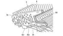
図4に示すように、この食器かご3はステンレス製で、太めの線材からなるかご枠3aに、所定の間隔を設けて網状かつかご状に形成した多数の線材3bを取り付けて形成されている。
As shown in FIG. 4, the
また、図1に示すように、ケース4は空気排出口4a1が設けられ、ケースの一部を構成するように膨出する透明合成樹脂製の固定ケース部4aに、ケースの一部を構成するように膨出する透明合成樹脂製の蓋体4bが、回動自在に軸支されて形成されている。なお、本実施形態ではケースを固定ケース部と蓋体で形成する例で説明したが、ケースは一体形状のものであってもよい。
Further, as shown in FIG. 1, the case 4 is provided with an
図5(a)〜(d)に示すように、包丁ケース6は多数の通気孔6a1が設けられた透明合成樹脂製板状の外ケース6aに、この外ケース6aと略同一の形状をなし、多数の通気孔6b1が設けられた内ケース6bが挿入嵌合されてケース状に形成されて、包丁Kの刃K1が収容される刃収容部6cが設けられ、さらに、包丁Kの挿入口側端部には把手K2の一部が挿入される挿入凹部6dが設けられている。
As shown in FIG. 5 (a) ~ (d) , the
この挿入凹部6dは、例えば丈高の台形状で、その深さ(長さ)は、通常把手K2の長さが100〜140mmであり、その長さの半分程度が包丁Kの取り出し挿入時の安全上好ましく、特に50〜70mmであるのが好ましく、また、その幅は把手K2の先端近傍を握りにくくするようにする。
The
また、外ケース6aには、挿入凹部6dの一側凹部6d1 (図7参照)、多数の通気孔6a1が設けられた主板部6a2と、この主板部6a2の外周端部に立設された係止突条6a3と、この係止突条6a3から内方に突出する係合突起6a4、主板部6a2先端に設けられた係合凹部6a5、食器かご3への取り付け時、食器かご3のかご枠3aに係合し主板部6a2の外面に設けられた取付係合片6a6と、線材3b間に挿入される回転防止用の回転防止片6a7が設けられている。
In addition, the
一方、図6(a)〜(b)に示すように、内ケース6bは、外ケース6aと略同一の形状、すなわち主板部6a2の形状に近く、図7に示すように、両ケースの挿入嵌合時、多数の通気孔6b1の位置及び挿入凹部6dの他側凹部6d2が一致するようになっており、さらに、内主板部6b1の外周端部には両ケースの挿入嵌合時、主板部6a2の係止突条6a3及び係合突起6a4と係合する内係止突条6b3が設けられ、また、係合凹部6a5と凹凸係合する係合突片6b5が設けられている。
On the other hand, as shown in FIG. 6 (a) ~ (b) , the
一般に上記外ケースや内ケースのような合成樹脂製の薄肉板状体を射出成形すると、外周端部に突条が形成されていない側に反る。このため、この反る側をお互いに外側にして、両ケースを挿入嵌合するようにすれば、双方の外側に向かう力が働いて、係合部分を介して両ケースがより強固に係合し、両ケースに空隙が生じることがない。 Generally, when a synthetic resin thin plate-like body such as the outer case or the inner case is injection-molded, the outer peripheral end warps to the side where no protrusion is formed. For this reason, if the warped sides are outside each other and both cases are inserted and fitted together, a force toward both outsides will work, and both cases will be more firmly engaged via the engaging portion. In addition, there is no gap between both cases.
なお、図中符号13は哺乳びんなどを乾燥させるための温風スタンドであり、倒立して挿入された哺乳びんなどの内部に温風を送り乾燥させるのに用いられる。符号14はシンクから落下する水を受ける水受けカップであり、本体に着脱自在に挿入されている。
本実施形態の食器乾燥器は、上記構造を有するので、図2に示すように、食器かご3に食器類(図示せず)を載置し、包丁Kを包丁ケース6に挿入し、温風供給装置5を作動させて、空気吸込口10から吸い込まれた空気を加熱して、空気吹出口11からケース4に吹き出し、食器類及び包丁Kを乾燥させる。
Since the tableware dryer of this embodiment has the above-mentioned structure, as shown in FIG. 2, tableware (not shown) is placed in the
乾燥完了後、必要に応じて食器類及び包丁Kを取り出して使用するが、包丁Kの取り出し時、通常把手K2の長さの半分は挿入凹部6cに挿入され、また、把手K2の先端近傍を握りにくくなっており、把手K2を握った手と刃収容部6cに収容された刃K1との距離を十分取る必要があるので、取り出し時、刃K1により手を傷つけることがなく安全であり、さらに、刃K1が刃収容部6cから露出している場合にも安全であり、特に包丁が上下逆さまに挿入され刃K1が上を向いて露出している場合にも安全である。また、包丁Kを包丁ケース6に挿入する場合、挿入凹部6dが設けられているので、把手K2の後半部分を握らないと、包丁Kを包丁ケース6に挿入することができないので、後半部分を握るため安全である。
After completion of drying, although retrieval and use dishware and kitchen knife K if necessary, at removal of the knife K, half the normal length of the handle K 2 is inserted into the
食器乾燥器が長期間使用され、包丁ケース6を洗浄する場合には、図3に示すような包丁ケース6の取付係合片6a6とかご枠3aの係合を外して、包丁ケース6をケース4外に取り出し、図6に示すような包丁ケース6の組立時とは逆に、係合凹部6a5と係合突片6b5との凹凸係合を解除し、内ケース6bを外ケース6aから引き出し両ケースを洗浄する。洗浄後は引き出し時とは逆に内ケース6bを外ケース6aに挿入、嵌合させ、係合凹部6a5と係合突片6b5を凹凸係合させる。このように、両ケースの挿脱は容易であると共に、両ケース間に空隙が生じず、美観に優れ、塵埃が溜まり難く衛生的であり、強度的にも強い。
When the tableware dryer is used for a long period of time and the
また、洗浄され組立てられた後の包丁ケース6は、再び図3に示すように、食器かご3に取り付けられるが、食器かご3への取り付け時、食器かご3のかご枠3aに取付係合片6a6を係合し、線材3b間に回転防止片6a7を挿入して行うので、包丁ケース6は容易かつ回転することもなく、確実に食器かご3に取り付けられる。
Further, the
上述した本実施形態の食器乾燥器によれば、包丁の取り出し挿入が安全で美観に優れ、衛生的で強固な包丁ケースを備えた食器乾燥器が実現される。 According to the tableware dryer of this embodiment mentioned above, the tableware dryer provided with the kitchen knife case which is safe and excellent in aesthetics, hygienic and strong, is realized.
1 食器乾燥器
2 本体
3 食器かご
3a かご枠
3b 線材
4 ケース
4a 固定ケース部
4b 蓋体
5 温風供給装置
6 包丁ケース
6a 外ケース
6a1 通気孔
6a5 係合凹部
6a6 取付係合片
6a7 回転防止片
6b 内ケース
6b1 通気孔
6b5 係合突片
6d 挿入凹部
DESCRIPTION OF SYMBOLS 1 Tableware dryer 2
Claims (2)
この本体上に設けられ食器かごに載置された食器類を収容するケースと、
このケースに温風を供給する温風供給装置を備えた食器乾燥器において、
前記食器かごには包丁が抜き差し自在に収納される包丁ケースが取り付けられ、
この包丁ケースは外ケースと内ケースが嵌合されてケース状をなしかつ、
前記内ケースの先端部には、係止突片が設けられ、この係止突片は前記外ケースの先端に設けられた係合凹部に係合することを特徴とする食器乾燥器。 The body,
A case for storing tableware provided on the main body and placed in a tableware basket;
In a tableware dryer equipped with a hot air supply device for supplying hot air to this case,
A knife case in which a knife is removably stored is attached to the tableware basket,
This knife case has a case shape with the outer case and inner case fitted together,
A locking projection is provided at the tip of the inner case, and the locking projection is engaged with an engagement recess provided at the tip of the outer case.
この本体上に設けられ食器かごに載置された食器類を収容するケースと、
このケースに温風を供給する温風供給装置を備えた食器乾燥器において、
前記食器かごには包丁が抜き差し自在に収納される包丁ケースが取り付けられ、
この包丁ケースには前記食器かごへの取り付け時、食器かごのかご枠に係合する取付係合片と食器かごの底部線材間に挿入される回転防止用の回転防止片が設けられたことを特徴とする食器乾燥器。 The body,
A case for storing tableware provided on the main body and placed in a tableware basket;
In a tableware dryer equipped with a hot air supply device for supplying hot air to this case,
A knife case in which a knife is removably stored is attached to the tableware basket,
The knife case is provided with an anti-rotation piece for preventing rotation inserted between an attachment engagement piece that engages with the basket frame of the tableware basket and a bottom wire of the tableware basket when attached to the tableware basket. Characteristic tableware dryer.
Priority Applications (1)
| Application Number | Priority Date | Filing Date | Title |
|---|---|---|---|
| JP2005126879A JP4564397B2 (en) | 2005-04-25 | 2005-04-25 | Tableware dryer |
Applications Claiming Priority (1)
| Application Number | Priority Date | Filing Date | Title |
|---|---|---|---|
| JP2005126879A JP4564397B2 (en) | 2005-04-25 | 2005-04-25 | Tableware dryer |
Publications (2)
| Publication Number | Publication Date |
|---|---|
| JP2006296963A JP2006296963A (en) | 2006-11-02 |
| JP4564397B2 true JP4564397B2 (en) | 2010-10-20 |
Family
ID=37465768
Family Applications (1)
| Application Number | Title | Priority Date | Filing Date |
|---|---|---|---|
| JP2005126879A Expired - Fee Related JP4564397B2 (en) | 2005-04-25 | 2005-04-25 | Tableware dryer |
Country Status (1)
| Country | Link |
|---|---|
| JP (1) | JP4564397B2 (en) |
Citations (2)
| Publication number | Priority date | Publication date | Assignee | Title |
|---|---|---|---|---|
| JPH0370747U (en) * | 1989-11-10 | 1991-07-16 | ||
| JP2002034887A (en) * | 2000-07-26 | 2002-02-05 | Sanyo Electric Co Ltd | Dish dryer |
Family Cites Families (2)
| Publication number | Priority date | Publication date | Assignee | Title |
|---|---|---|---|---|
| JP3849222B2 (en) * | 1997-04-09 | 2006-11-22 | 松下電器産業株式会社 | Kitchen knife storage device |
| JPH10328118A (en) * | 1997-05-28 | 1998-12-15 | Tiger Vacuum Bottle Co Ltd | Dish dryer |
-
2005
- 2005-04-25 JP JP2005126879A patent/JP4564397B2/en not_active Expired - Fee Related
Patent Citations (2)
| Publication number | Priority date | Publication date | Assignee | Title |
|---|---|---|---|---|
| JPH0370747U (en) * | 1989-11-10 | 1991-07-16 | ||
| JP2002034887A (en) * | 2000-07-26 | 2002-02-05 | Sanyo Electric Co Ltd | Dish dryer |
Also Published As
| Publication number | Publication date |
|---|---|
| JP2006296963A (en) | 2006-11-02 |
Similar Documents
| Publication | Publication Date | Title |
|---|---|---|
| USD611652S1 (en) | Cleaning device for an electric shaver | |
| USD509585S1 (en) | Handle for a dental water jet | |
| US7348572B2 (en) | Toothbrush sterilizer | |
| USD610152S1 (en) | Portion of a scanner | |
| JP4329840B2 (en) | Hair dryer | |
| JP4564397B2 (en) | Tableware dryer | |
| JP6078349B2 (en) | Kitchen knife | |
| JP6883732B2 (en) | dishwasher | |
| JP6727434B2 (en) | Hand dryer | |
| CN210842764U (en) | Draining basket device | |
| JP4207663B2 (en) | Tableware dryer | |
| JP5256703B2 (en) | cabinet | |
| JP5182156B2 (en) | Built-in cooking device | |
| JP2008125702A (en) | Dishwasher | |
| JP2004321707A (en) | Dish dryer | |
| JP2012249823A (en) | Dishwasher | |
| JP2001169994A (en) | Dish dryer | |
| JP4827037B2 (en) | Pull-out kitchenware dryer | |
| JP4827036B2 (en) | Pull-out kitchenware dryer | |
| KR200396673Y1 (en) | Sterilizer for Kitchen Utensils | |
| JP4533792B2 (en) | Tableware dryer | |
| JP5015066B2 (en) | System kitchen | |
| USD515694S1 (en) | Fan blade | |
| JPH0595885A (en) | Dish dryer | |
| JP2009254661A (en) | Drawer drying cabinet |
Legal Events
| Date | Code | Title | Description |
|---|---|---|---|
| A621 | Written request for application examination |
Free format text: JAPANESE INTERMEDIATE CODE: A621 Effective date: 20080204 |
|
| A711 | Notification of change in applicant |
Free format text: JAPANESE INTERMEDIATE CODE: A711 Effective date: 20080328 |
|
| A977 | Report on retrieval |
Free format text: JAPANESE INTERMEDIATE CODE: A971007 Effective date: 20100202 |
|
| A131 | Notification of reasons for refusal |
Free format text: JAPANESE INTERMEDIATE CODE: A131 Effective date: 20100302 |
|
| A521 | Written amendment |
Free format text: JAPANESE INTERMEDIATE CODE: A523 Effective date: 20100421 |
|
| A131 | Notification of reasons for refusal |
Free format text: JAPANESE INTERMEDIATE CODE: A131 Effective date: 20100518 |
|
| A521 | Written amendment |
Free format text: JAPANESE INTERMEDIATE CODE: A523 Effective date: 20100618 |
|
| TRDD | Decision of grant or rejection written | ||
| A01 | Written decision to grant a patent or to grant a registration (utility model) |
Free format text: JAPANESE INTERMEDIATE CODE: A01 Effective date: 20100706 |
|
| A01 | Written decision to grant a patent or to grant a registration (utility model) |
Free format text: JAPANESE INTERMEDIATE CODE: A01 |
|
| A61 | First payment of annual fees (during grant procedure) |
Free format text: JAPANESE INTERMEDIATE CODE: A61 Effective date: 20100730 |
|
| FPAY | Renewal fee payment (event date is renewal date of database) |
Free format text: PAYMENT UNTIL: 20130806 Year of fee payment: 3 |
|
| R150 | Certificate of patent or registration of utility model |
Ref document number: 4564397 Country of ref document: JP Free format text: JAPANESE INTERMEDIATE CODE: R150 Free format text: JAPANESE INTERMEDIATE CODE: R150 |
|
| S111 | Request for change of ownership or part of ownership |
Free format text: JAPANESE INTERMEDIATE CODE: R313115 |
|
| R350 | Written notification of registration of transfer |
Free format text: JAPANESE INTERMEDIATE CODE: R350 |
|
| S531 | Written request for registration of change of domicile |
Free format text: JAPANESE INTERMEDIATE CODE: R313531 |
|
| S533 | Written request for registration of change of name |
Free format text: JAPANESE INTERMEDIATE CODE: R313533 |
|
| R350 | Written notification of registration of transfer |
Free format text: JAPANESE INTERMEDIATE CODE: R350 |
|
| S111 | Request for change of ownership or part of ownership |
Free format text: JAPANESE INTERMEDIATE CODE: R313117 |
|
| R360 | Written notification for declining of transfer of rights |
Free format text: JAPANESE INTERMEDIATE CODE: R360 |
|
| R360 | Written notification for declining of transfer of rights |
Free format text: JAPANESE INTERMEDIATE CODE: R360 |
|
| R371 | Transfer withdrawn |
Free format text: JAPANESE INTERMEDIATE CODE: R371 |
|
| S111 | Request for change of ownership or part of ownership |
Free format text: JAPANESE INTERMEDIATE CODE: R313117 |
|
| R350 | Written notification of registration of transfer |
Free format text: JAPANESE INTERMEDIATE CODE: R350 |
|
| R250 | Receipt of annual fees |
Free format text: JAPANESE INTERMEDIATE CODE: R250 |
|
| R250 | Receipt of annual fees |
Free format text: JAPANESE INTERMEDIATE CODE: R250 |
|
| R250 | Receipt of annual fees |
Free format text: JAPANESE INTERMEDIATE CODE: R250 |
|
| R250 | Receipt of annual fees |
Free format text: JAPANESE INTERMEDIATE CODE: R250 |
|
| LAPS | Cancellation because of no payment of annual fees |