JP4559622B2 - Color image compression based on two-dimensional discrete wavelet transform yielding perceptually lossless images - Google Patents
Color image compression based on two-dimensional discrete wavelet transform yielding perceptually lossless images Download PDFInfo
- Publication number
- JP4559622B2 JP4559622B2 JP2000550279A JP2000550279A JP4559622B2 JP 4559622 B2 JP4559622 B2 JP 4559622B2 JP 2000550279 A JP2000550279 A JP 2000550279A JP 2000550279 A JP2000550279 A JP 2000550279A JP 4559622 B2 JP4559622 B2 JP 4559622B2
- Authority
- JP
- Japan
- Prior art keywords
- channel
- plane
- image
- color
- dwt
- Prior art date
- Legal status (The legal status is an assumption and is not a legal conclusion. Google has not performed a legal analysis and makes no representation as to the accuracy of the status listed.)
- Expired - Fee Related
Links
Images


Classifications
-
- H—ELECTRICITY
- H04—ELECTRIC COMMUNICATION TECHNIQUE
- H04N—PICTORIAL COMMUNICATION, e.g. TELEVISION
- H04N11/00—Colour television systems
- H04N11/04—Colour television systems using pulse code modulation
-
- H—ELECTRICITY
- H04—ELECTRIC COMMUNICATION TECHNIQUE
- H04N—PICTORIAL COMMUNICATION, e.g. TELEVISION
- H04N1/00—Scanning, transmission or reproduction of documents or the like, e.g. facsimile transmission; Details thereof
- H04N1/46—Colour picture communication systems
- H04N1/64—Systems for the transmission or the storage of the colour picture signal; Details therefor, e.g. coding or decoding means therefor
- H04N1/648—Transmitting or storing the primary (additive or subtractive) colour signals; Compression thereof
-
- H—ELECTRICITY
- H04—ELECTRIC COMMUNICATION TECHNIQUE
- H04N—PICTORIAL COMMUNICATION, e.g. TELEVISION
- H04N19/00—Methods or arrangements for coding, decoding, compressing or decompressing digital video signals
- H04N19/10—Methods or arrangements for coding, decoding, compressing or decompressing digital video signals using adaptive coding
- H04N19/169—Methods or arrangements for coding, decoding, compressing or decompressing digital video signals using adaptive coding characterised by the coding unit, i.e. the structural portion or semantic portion of the video signal being the object or the subject of the adaptive coding
- H04N19/186—Methods or arrangements for coding, decoding, compressing or decompressing digital video signals using adaptive coding characterised by the coding unit, i.e. the structural portion or semantic portion of the video signal being the object or the subject of the adaptive coding the unit being a colour or a chrominance component
-
- H—ELECTRICITY
- H04—ELECTRIC COMMUNICATION TECHNIQUE
- H04N—PICTORIAL COMMUNICATION, e.g. TELEVISION
- H04N19/00—Methods or arrangements for coding, decoding, compressing or decompressing digital video signals
- H04N19/60—Methods or arrangements for coding, decoding, compressing or decompressing digital video signals using transform coding
- H04N19/625—Methods or arrangements for coding, decoding, compressing or decompressing digital video signals using transform coding using discrete cosine transform [DCT]
-
- H—ELECTRICITY
- H04—ELECTRIC COMMUNICATION TECHNIQUE
- H04N—PICTORIAL COMMUNICATION, e.g. TELEVISION
- H04N19/00—Methods or arrangements for coding, decoding, compressing or decompressing digital video signals
- H04N19/60—Methods or arrangements for coding, decoding, compressing or decompressing digital video signals using transform coding
- H04N19/63—Methods or arrangements for coding, decoding, compressing or decompressing digital video signals using transform coding using sub-band based transform, e.g. wavelets
-
- H—ELECTRICITY
- H04—ELECTRIC COMMUNICATION TECHNIQUE
- H04N—PICTORIAL COMMUNICATION, e.g. TELEVISION
- H04N19/00—Methods or arrangements for coding, decoding, compressing or decompressing digital video signals
- H04N19/10—Methods or arrangements for coding, decoding, compressing or decompressing digital video signals using adaptive coding
- H04N19/102—Methods or arrangements for coding, decoding, compressing or decompressing digital video signals using adaptive coding characterised by the element, parameter or selection affected or controlled by the adaptive coding
Landscapes
- Engineering & Computer Science (AREA)
- Multimedia (AREA)
- Signal Processing (AREA)
- Physics & Mathematics (AREA)
- Discrete Mathematics (AREA)
- General Physics & Mathematics (AREA)
- Compression Or Coding Systems Of Tv Signals (AREA)
- Compression Of Band Width Or Redundancy In Fax (AREA)
- Color Television Systems (AREA)
- Image Processing (AREA)
Description
【0001】
(発明の背景)
(1.発明の分野)
本発明は一般に画像処理に関する。より詳細には、本発明は画像圧縮のためのコード化および量子化に関する。
【0002】
(2.関連技術の説明)
ある場面、情景、または物体の画像を取り込むと、その画像は周知のピクセルアレイとして表される。ある画像の各ピクセルは、1つ以上のカラー・プレーンに関連する値を有する。ディジタル・カメラなどの撮像装置によって画像を取り込むと、その画像はバイエル・パターンとして知られるカラー・フィルタ・アレイ(CFA)パターンに取り込まれる場合が多い。バイエル・パターン内の配置された各ピクセルは、3種類の基本レンダリング・カラー(赤(R)、緑(G)、青(B))の1つのみに関連する強度値を持つ。バイエル・パターンではピクセルを以下のように配置する。
G R G R ...
B G B G ...
G R G R ...
B G B G ...
【0003】
BピクセルまたはRピクセルの2倍の数のG関連ピクセルが存在するので、Gすなわち緑のカラー・プレーンは2つの別々のカラー・プレーンG1(Rピクセルと同じ行のGピクセル)およびG2(Bピクセルと同じ行のGピクセル)と見なすことができる。したがって、バイエル・パターンの「生」画像は4つの独立したカラー・プレーンを含むものと見なすことができる。フルカラー(フルカラーに分解した)画像(たとえば、レンダリング用)を得るために、配置された各ピクセルは、1つだけでなく、RGB3種類すべての成分を有していなければならない。これを達成するため、カラー補間として知られるプロセスを使用し、近隣ピクセルに基づいて1つのピクセルに関する欠落カラー成分を推定する。
【0004】
ある画像を取り込み、必要に応じてカラー補間した後、その画像を記憶または伝送するために必要になると思われるビット総数を減らすことを目的として「圧縮」すなわち縮小する場合が多い。このような画像圧縮は通常、カラー補間後に適用されるが、ある場合には、カラー補間前の画像が依然としてバイエル・パターンの生画像フォーマットになっている間に適当な圧縮を実行することが有利になる。画像圧縮は、ビデオ会議、ディジタル撮像、ネットワークによるビデオ・ストリーミングなどのマルチメディアアプリケーションでは重要な役割を果たす。このようなアプリケーションの画像圧縮方式は、特定のアプリケーションについて容認できる画像品質を維持しながら、画像の記憶または転送のビットレートを低減するように設計しなければならない。
【0005】
画像圧縮技法は、「損失」または「無損失」のいずれかとして分類することができる。無損失圧縮の場合、圧縮した画像を圧縮解除したときに、圧縮前の元の画像を正確に回復することができる。その結果として、無損失技法では、その圧縮比が画像のエントロピによって決まり、通常、高い圧縮比を達成せず、しかも元の画像情報のうちのかなりの部分を保存するので、コンピュータ的に言えば不経済となる。対照的に、損失圧縮方式では、元の画像の近似しか得られず、より高い圧縮比を達成できるが、無損失技法に比べ、画像品質の損失を伴う場合が多い。
【0006】
このような損失技法の1つは、JPEGとして知られる変換ベースのコーディングであり、これは周知の離散コサイン変換(DCT)を使用して入力画像のピクセルを変換する。圧縮を達成するために、結果として得られる変換済みピクセル値をより小さい値のセットにマッピングするか量子化する。圧縮解除される圧縮画像の品質は、変換済みピクセルの量子化をどのように行うかに大きく依存する。圧縮比(圧縮画像と比較した元の生画像のサイズ)も量子化の影響を受けることになるが、量子化後のデータの2進コード化によって高めることができる。
【0007】
さらに、JPEGなどの高圧縮比アルゴリズムには、「ブロック化アーチファクト」などの欠点がある。このようなアルゴリズムの場合、画像は、8×8ブロックまたは16×16ブロックなどのピクセル・ブロックに分割される。これらのブロックは互いに独立して処理されるので、ブロック間において観察できるほどの輝度またはカラーの不連続が存在し、これが「ブロック化アーチファクト」を構成する。
【0008】
上記したようなあるいはその他の画像圧縮方式は、高い圧縮比と、時に容認できる圧縮解除画像品質も達成するが、画像が「輝度クロミナンス」のフォーマットであるときにより適切に作用する。選択した基本カラー(赤、緑、青など)の混合としてピクセルカラーを表すカラー補間したフルRGB画像「空間」(すなわち、フォーマット)またはバイエル・パターンとは異なり、輝度クロミナンス・フォーマット画像は色相と飽和レベルによって各ピクセルを定義する。ディジタル・カメラなどの撮像装置は通常、バイエル・パターン・フォーマットで画像を取り込むので、まず画像をフルカラー(RGB)に分解しカラー補間し、輝度クロミナンス技法を適用する前に、その「色空間」をYCrCbなどの輝度クロミナンス・フォーマットに変換しなければならない。このようなカラー補間と色空間変換は、コストが非常に高くなるとともに時間がかかる場合が多く望ましいものではない。
【0009】
図1はこのような従来の手法の1つを示している。たとえばディジタル・カメラなどの装置から取り込んだ元の画像100は、通常、バイエル・パターンなどの生画像フォーマットになっている。このため、各ピクセルはフルカラーの表現を有することはない。ついで、一度に全部または1ブロックずつ、カラー補間ピクセル手順110に画像を渡す。カラー補間手順では画像100からフルカラー・ピクセルを生成し、その各ピクセルはフルカラー値(たとえば、R、G、Bの各成分)に分解される。次に、RGBからYUVまたはその他の適切な空間にフルカラー画像を色空間変換する(ブロック120)。このような変換は、達成可能な圧縮比を改善する。変換が完了すると、プライマリー圧縮手順(ブロック130)に画像を渡す。このような圧縮は、JPEGまたはフーリエ解析などの様々な手順を含むことができるが、1つのコンポーネントとして量子化手順を有する場合が多い。画像ピクセルを表す一定範囲の値をより小さい範囲の値にマッピングすることによって、画像を量子化する。圧縮後、転送または記憶に適したものになるように、圧縮画像値をコード化することができる(ブロック140)。
【0010】
このような従来の手法には、いくつかの欠点がある。第一に、特にカラー補間および色空間変換において手順全体が計算上、複雑なものになっている。色空間変換だけでも(たとえば、RGBからYCrCb空間の場合)、各ピクセルごとに9回の乗算と6回の加算とを必要とする。多くの場合、このような複雑な技法は、ディジタル・カメラなどの小型のコスト重視の装置で効果的に実施することはできない。
【0011】
ディジタル・カメラまたはその他の撮像装置上で画像を圧縮する場合、上記の圧縮技法は効果的ではないかまたは非常に高いものになるだろう。したがって、それを使用するディジタル・カメラのコストを低減するように、コンピュータ上での安価な画像量子化圧縮技法が必要である。最初にカラー補間を実行する必要性を回避するために、携帯用撮像装置によって生成されたバイエル・パターンの生画像データに直接適用可能であり、高圧縮比を達成するために様々なカラー・プレーン間の相関関係を利用可能な量子化圧縮方法を開発しなければならない。さらに、画像品質を維持しながら、撮像装置からの画像取込みとローカル・メモリへの記憶または転送をよりリアルタイムで実行できるように、量子化および圧縮の速度を高めることが必要である。
【0012】
(発明の概要)
カラー・プレーン弁別チャネルを含む複数のチャネルに生画像データを分割することを含み、生画像データを構成するカラー・プレーン間の相関関係を利用し、次に2次元離散ウェーブレット変換を使用してこれらのチャネルのそれぞれを別々に圧縮し、その圧縮が量子化を使用し、圧縮チャネルデータの圧縮解除が知覚的に無損失の画像をもたらす方法を開示する。
【0013】
本発明の方法および装置の目的、特徴、利点については、以下に示す説明から明らかになるだろう。
【0014】
(発明の詳細な説明)
次に、添付図面を参照し、本発明の例示的な実施形態について説明する。例示的な実施形態は、本発明の態様を示すためのものであり、本発明の範囲を限定するものと解釈してはならない。また、主にブロック図または流れ図に関連して例示的な実施形態を説明する。流れ図の場合、流れ図内の各ブロックは、方法ステップと、その方法ステップを実行するための装置要素の両方を表している。実施形態に応じて、対応する装置要素は、ハードウェア、ソフトウェア、ファームウェア、あるいはそれらの組合せとして構成することができる。
【0015】
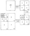
図2は本発明の一実施形態による画像圧縮データ・フローを示している。
静止画撮像または動画撮像などのディジタルアプリケーションでは、圧縮解除のためにそれを転送し表示する前に、所定のレベルの品質を維持しながら、ディジタル・カメラによって取り込んだ画像などの元の画像のサイズをできるだけ圧縮することが望ましい。理想を言えば、選択した圧縮技法はどのようなデータ転送メカニズムにも適用することが望ましい。ここで開示する圧縮技法は、本発明の1つまたは複数の実施形態の主題であり、色および光に対する人間の視覚系の反応を利用して画像品質を維持するよう具体的に開発されたものである。
【0016】
前述のように、ディジタル・カメラまたはその他の同様の装置によって取り込まれた生画像は通常は、バイエル・パターンで表される。センサ・アレイ200は1組のピクセルの配置を有する「センサ群」であり、情景/場面からセンサに入射する光の強度値を各位置(ピクセル)ごとに撮像する。バイエル・パターンでは、センサ・アレイ内の画像(以下「オリジナル画像」という)200の各ピクセル配置は、赤(R)、緑(G)、青(B)のカラー・プレーンとの関連を有することになる。バイエル・パターンはすべてのRおよびBについて2つの関連値を有するので、緑のカラー・プレーンは2つのプレーンG1およびG2と見なすことができる。G1関連ピクセルは元の画像200内のR関連ピクセルと同じ行のバイエル・パターンに位置し、G2関連ピクセルはB関連ピクセルと同じ行に位置する。
【0017】
本発明の一実施形態によれば、R関連ピクセルとそのG1関連近隣ピクセルとの相関関係ならびにB関連ピクセルとその近隣G2ピクセルとの相関関係はどちらも有利に活用される。本実施形態では、カラー補間または色空間変換あるいはその両方の必要なしに、バイエル・パターン内のピクセルを直接圧縮することができる。G1およびG2関連ピクセルを圧縮ブロックに直接渡す(ブロック212および216)。RピクセルとBピクセルの処理はあまり直接的ではない。Rピクセル値はその西側近隣G1ピクセル値によって減算される(ブロック205)。この差(R−G1)を圧縮ブロックに渡す(ブロック210)。同様に、各B関連ピクセルはその東側近隣G2関連ピクセルから減算される(ブロック206)。次にこの差(B−G2)を圧縮ブロックに渡す(ブロック216)。
【0018】
本発明の一実施形態によれば、カラー・プレーン間の強い相関関係を利用するために、弁別チャネルR−G1およびB−G2が作成される。これらの「チャネル」はG1およびG2チャネルとともに、それぞれ適切な圧縮段階に渡される。一実施形態では減算を使用することによって純粋カラー・チャネルの相関関係を解除するが、他の相関関係解除方法も使用することができる。緑は人間の視覚系にとって(R、G、Bの3色のうちで)最も知覚可能な色なので、緑のプレーンG1およびG2はチャネルとして保存され、赤と青の相関関係を解除するための基準チャネルとして使用する。
【0019】
R−G1、G1、G2、B−G2という4つのチャネルのそれぞれは、圧縮ブロック210、212、214、216にそれぞれ渡される。各圧縮ブロック210、212、214、216では、本発明の一実施形態によれば、2つのプロセスが行われる。第1のプロセスは2次元離散ウェーブレット変換(2−D DWT)である。DWTは、画像の急激な変化と不連続、その結果、画像のエッジ・フィーチャをより正確にかつ効率よく記述するので、フーリエその他の周期ベースの変換より画像圧縮の際に有用である。2−D DWTは、図4に関連して以下に説明し図示するように、画像の「副帯(sub-bands)」を生成する。DWTの実行後、量子化として知られる第2のプロセスを実行する。
【0020】
量子化は、m<nの場合にn通りの値のセットをm通りの値のセットにマッピングする手順である。量子化により、DWT画像データ・セットに可能なデータ値の総数が削減される。このマッピングはy=f(x)という数式に応じて実行される。ここで、xはDWTデータ値であり、yは量子化データ値である。このような式により、画像を表すために必要な総ビット数は低減される。これにより何らかの誤差が発生するが、当技術分野には、誤差を低減するために使用可能な方法がいくつか存在する。変換済み画像データを量子化した後、そのデータをコード化する。コード化ユニットでは、量子化データが好ましい表現を持つように配置(パック)する。この圧縮コード化画像データは、その後、媒体に記憶するか、あるシステムから別のシステムに転送するか、ネットワークなどの通信経路により配布することができる。さらに、この圧縮コード化画像データは、単一フレームとして収集し転送する必要はないが、コード化値単位でその宛先にストリーミングすることができる。
【0021】
元の画像のサイズを圧縮画像のサイズで割った圧縮比は、DWT変換、量子化、コード化に使用する精密なパラメータに応じて、変動することになる。本実施形態は、圧縮解除した画像品質を有利に高め、圧縮解除の複雑さを低下し、圧縮比を最適化するように機能することができる圧縮プロセスの機能強化を可能にする。
【0022】
他の画像圧縮技法もDWTを使用可能である場合、圧縮解除した画像の品質は主に使用した量子化によって決まることになる。本発明の重要な一態様は知覚的に無損失の手法であり、その結果は圧縮解除したときに無損失であると人間の視覚系によって近くされる損失圧縮である。さらに、本実施形態で採用する量子化手法は高速かつ容易な計算が可能であり、圧縮が実施されるハードウェアに対してよりリアルタイムなパフォーマンスをもたらす。本発明の一実施形態では、DWTの特性を利用して画像の副帯を作成することにより、副帯特性およびカラー・チャネル特性に応答する適応量子化手順が提供される。
【0023】
各チャネル(R−G1、G1、G2、B−G2)について、2−D DWTプロセスによって生成された各画像副帯ごとに量子化しきい値が定義される。このような各しきい値Q(s,c)では、「s」が副帯を表し、「c」がチャネルを表すが、そのチャネル「c」および副帯「s」におけるDWT結果値を量子化する際に使用する。したがって、値Xsc(またはこのような値を求める際に使用するDWT係数)の場合、量子化値Yscは単に次のようになる。
【0024】
【数1】

【0025】
図3は本発明の一実施形態による圧縮コード化画像の回復を示している。
デコード・ブロックと、逆量子化ブロックと、逆DWTブロックは、圧縮コード化画像データ240(図2を参照)からオリジナル画像200を回復するプロセスを構成する。圧縮が「損失性」なので、得られるデコード圧縮解除画像は、元の画像を正確にピクセルごとに再構築したものにはならない。しかし、本発明の様々な実施形態の主題である知覚的に無損失の量子化技法とDWT特性を使用することにより、その損失を人間の視覚に知覚できない程度のものとすることができるので、この方法により圧縮解除した画像の品質は他の損失技法より改善される。さらに、他の逆技法と比較したときに逆DWT手順は容易であるため、高速かつ容易な実施に適したものになる。
【0026】
圧縮コード化画像データ240は、1チャネルずつならびに1副帯ずつ効率よく記憶することができる(図4を参照)。したがって、圧縮コード化チャネル(R−G1)、G1、G2、(B−G2)は、別々にデコードし圧縮解除することができる。まず、各チャネルに属するデータを、ゼロ・ランレングス、ハフマン・デコードなどを利用してデコードする(ブロック310、312、314、316)。各チャネルおよび副帯のデータは、他の副帯およびチャネルのデータとは異なる技法を使用してコード化されていることもあり得るので、コード化技法の違いを考慮に入れてデコードする必要がある。次に、各チャネルのデコード・データを圧縮解除する(ブロック320、322、324、326)。図2に示す圧縮ブロックと同様に、圧縮解除は、デコード・データの量子化解除と逆DWT(IDWT)の実行という2つの手順から構成される。
【0027】
逆量子化ブロックは単にデコード・データ(量子化DWT係数である)の値に所与の副帯および適切なチャネル用の量子化しきい値Q(s,c)を掛けるだけである。逆量子化後、各チャネルおよび副帯のデータごとに逆DWTを実行する。逆DWTが完了すると、1ピクセルずつ、オリジナル画像200の近似を求めることができる。(R−G1)回復値にG1を加算し(ブロック325)、(B−G2)回復値にG2を加算する(ブロック326)ことにより、元のセンサ・アレイ200からの各バイエル・パターン・ピクセル値R、G1、G2、Bをほぼ回復することができる。回復したR、回復したG1、回復したB2、回復したBの各値は、元の画像200の値と同一である場合もあれば、同一ではない場合もあるが、カラー・チャネル相関関係の利用により、視覚的に無損失または知覚的に無損失の特性を示すことになる。したがって、回復した画像は高品質のものになる。本発明の他の態様によれば、適切な量子化しきい値によって逆DWT係数を変更することにより、逆量子化プロセスを逆DWTと組み合わせることができる。
【0028】
圧縮解除は、ハードウェアまたはソフトウェアとして実施するか、両者のうちの一方または組合せによって実施することができ、コード化圧縮プロセスの機能を実行する装置とは物理的に分離したものにすることができる。損失圧縮方式の基本データ・フローは圧縮と圧縮解除からなり、多くの場合、圧縮ブロックから圧縮解除機能にアクセスできる所望の宛先への中間転送も含むことになる。
【0029】
図4は2次元(2−D)DWTを画像に反復適用した結果を示している。
「An Integrated Systolic Architecture for Decompositon and Reconstruction of Signals Using Wavelet Transforms」という名称の同時係属米国特許出願第08/767976号(以下「特許出願’976号」という)に記載されているように、画像空間上で2−D DWTを適用すると、その結果、4つの「副帯」が作成される。たとえば、図4は、画像Sが2−D DWTによって4つの副帯S1、S2、S3、S4に分解されることを示している。これらのうち、最も重要な副帯はS1である。この副帯S1は二重低域フィルタ処理に基づいて生成されるので、「LL」副帯ともいう。S1(LL)は本質的に元の画像Sのスケーリング済み近似になっており、最も顕著な画像情報を含む。
【0030】
副帯S2、S3、S4はエッジ情報を含み、入力画像が雑音のあるものである場合、その雑音のかなりの部分も含む。副帯S2、S3、S4は、それを生成するために使用する様々な低域および高域フィルタ処理により、それぞれHL副帯、LH副帯、HH副帯ともいう。副帯S2、S3、S4は知覚的にはS1副帯ほど重要ではないので、その値がより大幅に圧縮されるように、これらの副帯をより「大まかに」量子化する(すなわち、より大きいしきい値Qを割り当てる)ことができる。より高レベルのDWTを生成する際にS1副帯を使用するので、この副帯は直接量子化する必要がない場合もある。前述のように、本発明の一実施形態によれば、オリジナル画像は1チャネルずつ2−D DWTが行われる。本発明の一実施形態で使用する4つのチャネルは(R−G1)、G1、G2、(B−G2)を含む。これらのチャネルのそれぞれを構成するデータは、それについて2−D DWTが行われる「画像」そのものと見なすことができる。4つの副帯S1、S2、S3、S4はレベル1のDWTを構成する。したがって、図4においてLL1、HL1、LH1、HH1という名称の下にある添字は、これらの副帯がレベル1に属すことを示している。
【0031】
レベル1の副帯S1、S2、S3、S4は、画像Sに2−D DWTを1回適用した結果である。副帯結果S1に2−D DWTをもう一度適用した場合、レベル2の2−D DWTが実行されたといわれる。レベル2の2−D DWTの結果、4つの新しい副帯S11、S12、S13、S14が生成されるものと思われるが、これらはレベル1の2−D DWTにより副帯S1から生成された副帯である。これらの副帯S11、S12、S13、S14は、レベル2のDWT副帯なので、それぞれLL2、HL2、LH2、HH2という名称を有する。この場合も、LL2副帯S11はS1からの最も顕著なフィーチャを含み、S12、S13、S14副帯は副帯S1からのエッジ情報とあるいは雑音情報をも含む。したがって、より多くのレベルのDWT分解と、その結果、より多くの画像副帯を得るために、各レベルの副帯に2−D DWTを何回も適用することができる。
【0032】
本発明の一実施形態では、レベル1の2−D DWT手順のみ考慮する。より多くのレベルの2−D DWT処理が行われる場合、新たに作成された副帯のそれぞれには、そこに存在する各チャネル用のQまたは量子化しきい値が割り当てられる。9−7両直交スプラインDWTフィルタの場合、与えられた副帯「s」およびチャネル「c」用のQ(s,c)値は、経験的に求められる。この研究の結果は図5の表に示す。
【0033】
図5は所与の副帯およびチャネル用のサンプル量子化しきい値を示す表である。
量子化しきい値Q(s,c)は様々な方法で決定または選択することができる。本発明の様々な実施形態を考案する際に行った研究の1つでは、1組のDWT圧縮画像に対する1群の観察者の知覚に関する経験的データを収集した。このような実験では、量子化によるアーチファクトが観察可能になるまで、しきい値Q(s,c)を増加した。この研究のために、異なる特性を有する様々な画像を選択した。図5の表は、この研究の結果を示し、どの画像にも適用可能であることが統計的に保証されている。ただし、当技術分野で周知の9−7両直交スプライン・フィルタをDWTの基礎として使用することを条件とする。DCTなどの異なる技法または異なる基礎を使用するDWTの場合、それぞれのフィルタが同じ画像についてそれぞれ異なる提示を行うので、新しい量子化しきい値を選択または決定する必要がありうる。本発明の一実施形態ではこのような値をROMにプリロードすることができ、他の実施形態ではこれらの値を変更できるように書換可能なメモリに書き込むことができる。
【0034】
図4を参照すると、S1、S2、S3、S4という副帯はいずれもレベル1のDWTに属す。副帯S4は、S2およびS3副帯より約5倍大きい量子化しきい値を有する。したがって、S4副帯の情報(データ値)はより大きい程度まで量子化され、このため、より大幅に圧縮される。より大きい量子化しきい値により生じうる誤差と、その結果としてのマップ値の減少は許容できるものである。というのは、S4副帯は対角エッジおよび雑音など、知覚可能な画像の中では最も視覚的に関連の少ないものの一つを示すにすぎないからである。前述のように、S1は元の画像Sのうち顕著で、かつ視覚的に重大な情報のほとんどを含む。kレベルのDWTの場合、最も低いk−1のLL副帯はそれ自体がより高いレベルのLL、LH、HL、HH副帯にさらに分解されるので、その副帯は保存され(すなわち、Qは1)、したがって量子化されない。LLkまたは最も高いレベルのDWT副帯では量子化が補償されているものと思われ、その副帯に対してより高いレベルの分解は行われないので、その副帯は量子化される(Q>1)。すべてのレベルの副帯S2およびS3は同じレベルのS1副帯とS4副帯の中間に位置する量子化しきい値を有する。
【0035】
チャネルに関しては、R、G、Bと、次に(R−G1)および(B−G2)について量子化しきい値を決定した。このG値はG1とG2の両方に当てはまるものである。一般に、青は緑(G1、G2)および赤より大まかに(より大きいしきい値で)量子化することができる。しかし、本発明の実施形態では、圧縮プロセスで純粋なRおよびBではなくチャネル(R−G1)および(B−G2)について考慮する。このような「弁別」または相関関係解除チャネルは、純粋なカラー・チャネルR、G、Bよりかなり大きい量子化しきい値を有する。これは、画像のエッジ情報がG1およびG2プレーン(チャネル)で補償されることによる。これらのG1およびG2値をRおよびBのプレーン値からそれぞれ減算すると、その結果得られる差によって、G1およびG2で見られないクロミナンス成分がRおよびBプレーンに保存される。したがって、弁別チャネル(R−G1)および(B−G2)によって、全体的な画像およびその知覚品質に対するRおよびBプレーンの作用が最適化される。
【0036】
観察結果によれば、弁別チャネル(R−G1)および(B−G2)のS4副帯は、G1およびG2チャネルに含まれる情報と知覚的に異なる画像情報を一切含まず、したがって、その副帯全体にゼロ値が割り当てられる(Q値が00)ことが分かっている。本発明の一実施形態によれば、そこには知覚可能な情報が一切存在しないので、弁別チャネルに関して副帯S4を記憶する必要はない。DWTレベルが高くなるほど、前のレベルの入力副帯LLについて得られる精度または分解能も高くなる。図4には3レベルのDWTが示されているが、設計ニーズに応じて任意の数のDWTレベルを生成することができる。
【0037】
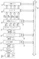
図6は本発明の一実施形態のブロック図である。
図2および図3に関連して説明した本発明の一実施形態によれば、圧縮および圧縮解除プロセスは、一方が量子化(および逆量子化)用であり、もう一方の別個の段階がDWT(および逆DWT)用である2つの段階に分割される。しかし、本発明の他の実施形態によれば、量子化(逆量子化)段階はDWT(および逆DWT)に合体することができる。DWTおよび逆DWT出力は1組のカスケード・フィルタ(特許出願’976号を参照)によって生成され、そのフィルタの係数はDWT(および逆DWT)関数の係数である。これらの係数に入力ピクセル値を掛け、その積を選択的に加算してDWT出力を生成する。量子化しきい値をDWT係数と代数的に結合した場合、DWT計算自体の最中に量子化が達成されることになる。
【0038】
図6の実施形態では、1次元(1−D)DWTを2回繰り返すことによって2−D DWTを実施する。この手法は、DWTフィルタ(特許出願’976号)が分離可能であることから可能である。また、このようなフィルタが実現可能である場合、単一2次元フィルタを使用して、2次元DWTまたはその他の2次元変換を実施することが可能である。対照的に、特許出願’976号に概要が示されているように、1次元フィルタ手法では、行単位方式でDWTを実行し、行単位のDWTの結果に対して列単位方式でDWTを実行する。たとえば、図6に示すように、チャネル「c」600について検討する。これは、本発明の一実施形態では、特定のカラー/弁別チャネルG1、G2、(R−G1)、または(B−G2)からのピクセル・データを表すが、他の実施形態では、画像全体または画像の一部分を表すこともできる。まず、1−D DWTモジュール610によって行単位のDWTを実行する。1組の制御信号#1がこの行単位のDWTの動作を決定するとともに以下に示すようにDWTのレベルに応じて係数を供給する。モジュール610はチャネル「c」から「L」帯域と「H」帯域を生成する。
【0039】
行単位のDWTが実行されると、得られた「L」帯域と「H」帯域がマトリックス・トランスポーザ回路620によって転置される。このようなマトリックス・トランスポーザ回路は当技術分野では周知のものである。マトリックス・トランスポーザ回路620は、マトリックス・トランスポーザ回路620からの結果を第2の1−D DWTモジュール630に入力として1列ずつ供給する。第2の1−D DWTモジュール630は、1組の制御信号#2により、必要に応じて制御され、係数が供給される。マトリックス・トランスポーザ回路620から転置された1−D DWT行単位データに対して列単位で1−D DWTを実行した結果は、2−D DWT結果データ640として示される。行単位の1−D DWT転置と列単位の1−D DWTを通過するたびに、その通過は2−D DWTの実行と同等のものになる。結果データ640は、副帯LL、HL、LH、HHから構成され、図4で参照し説明したようにDWTの1つのレベルを含む。
【0040】
前述のプロセスは、DWTの1つのレベルから結果を生成するためのものである。3レベルのDWT分解などの複数レベルが所望の場合、カウンタを使用して、そのカウンタに値3をロードしてもよい。2−D DWTサイクルが完了するインスタンスごとに、カウントが減分される。判断ブロック650では、このカウンタをチェックして、他のDWTレベルが必要かどうかを判定することができる。他のレベルが所望であれば、「LL」副帯を2−D DWTプロセスに戻し、そこからもう1組の副帯を生成する。図4はたとえば3レベルの2−D DWT結果を示している。各レベルでは、kがレベルである副帯LLkを入力として使用し、次に2−D DWTの使用によりさらに4つの副帯に分解する。この手順は、最終所望レベルのDWT分解に達するまで繰り返す。また、DWTの各レベルが完了すると、副帯HL、LH、HHはエンコーダ660に送られ、そのエンコーダがハフマンまたはランレングス・コード化などの2進コード化をそのデータに対して実行する。次に、コード化データを圧縮チャネルc’670の一部分として記憶する。各レベルでは、最終レベルのDWT分解前に、LL副帯をコード化しない。というのは、その副帯はさらに副帯を生成するために2−D DWTプロセスにフィードバックされるからである。DWTの最終レベルでは、LL副帯はコード化するためにコード化ブロック660に送られる。エンコーダ660の出力は、記憶しアセンブルされ、完了すると圧縮チャネルc’670を構成することになる。前述のように、チャネルR−G1、G1、G2、B−G2のそれぞれは処理されて圧縮チャネルになる。
【0041】
DWTフィルタ処理(DWTモジュール610および630によって実行される)中に量子化を達成するために、量子化係数Q(s,c)によってフィルタ処理係数を変更しなければならず、その場合、sは副帯であり、cはチャネルである。DWT係数の変更はフィルタの性質および処理中の副帯によって様々であり、以下のように要約される。
【0042】
行単位1−D DWT:
・ LLk-l副帯(またはk=1の場合はソース画像)による低域フィルタ処理(副帯Lの生成): フィルタの各重み(係数)liは以下の因数によってスケーリングされる。
【数2】
【数3】
列単位1−D DWT:
・ LおよびH副帯による低域フィルタ処理(副帯LLおよびLHの生成): フィルタの各重み(係数)liは以下の因数によってスケーリングされる。
【数4】
【数5】
・ H副帯による高域フィルタ処理(副帯HHの生成): フィルタの各重み(係数)hiは以下の因数によってスケーリングされる。
【数6】
【0045】
・ LL副帯:
【数7】
【数8】
【数9】
【数10】
図7は本発明の一実施形態による画像処理装置のブロック図である。
図7は、本発明の少なくとも一実施形態を組み込んだ撮像装置の内部画像処理圧縮コンポーネントのブロック図である。図7の例示的な回路では、センサ700は何らかの場面/環境からカラー/強度値であるピクセル成分を生成する。センサ700によって生成されたnビット・ピクセル値はキャプチャ・インタフェース710に送られる。本発明に関連して言えば、センサ700は通常、配置されたある「感知素子」によりR、G、Bいずれか1つの成分を感知することになる。したがって、各ピクセルの強度値は3つのカラー・プレーンの1つのみに関連し、まとまって上記に示すようなバイエル・パターンを形成することができる。キャプチャ・インタフェース710は、センサによって生成された画像を分解し、個々のピクセルに強度値を割り当てる。本発明の実施形態の少なくとも1つでは、画像全体のこのようなピクセルのすべてからなるセットはバイエル・パターンになっている。
【0047】
センサ・プレーン内のピクセル・セルの一部がその場面/情景の照明条件に適切に応答できないことはどのセンサ装置でもよくあることである。その結果、これらのセルから生成されたピクセル値は欠陥のあるものになる可能性がある。これらのピクセルは「デッド・ピクセル」と呼ばれる。「ピクセル置換」ユニット715は、その行内の直前に有効ピクセルで各デッド・ピクセルを置き換えるものである。
【0048】
RAMテーブル716は、センサによって供給されるデッド・ピクセルの行インデックスと列インデックスから構成される。このRAMテーブル716は、取り込んだ画像に関するデッド・ピクセルの位置を識別する助けとなる。コンパンディング・モジュール725は、センサから取り込まれたnビット(通常はn=10)強度の元の各ピクセルをmビットの強度値に変換するように設計された回路であり、その場合、m<n(通常はm=8)である。センサ700およびキャプチャ・インタフェース710がmビットのピクセルあたりの値を付与する場合、コンパンディング・モジュール725は不要である。
【0049】
本発明の少なくとも一実施形態によれば、前述のように、カラー補間または色空間変換あるいはその両方に頼らずにmビットのピクセル値(複数も可)のセットを直接圧縮することができる。チャネル・ジェネレータ717はコンパンディング・モジュール725に結合され、バイエル・パターンに応じて配置可能なmビットのピクセル・データ値をそこから受け取る。各mビット値は、4つのチャネル(R−G1)、G1、G2、(B−G2)を生成するためにチャネル・ジェネレータが使用する。たとえば、1行ずつピクセルを取り込む場合、第1の行はRおよびG1のピクセル値をもたらし、その結果、チャネル(R−G1)およびG1のみの出力をもたらすことになるだろう。次に取り込んだ行はG2および(B−G2)チャネルをもたらすことになるだろう。チャネル・ジェネレータ727は、1行の間に2つのチャネルを送り、次の行の間に残りの2つのチャネルを送る。
【0050】
次にこれらのチャネルは圧縮及び量子化ユニット728に入力される。RAMテーブル729は、前述の圧縮技法を実行する際に所望の各チャネル/副帯ごとにDWT係数または量子化しきい値あるいはその両方を記憶するために使用する。さらに、必要なDWT計算を実行するために圧縮及び量子化ユニット728内に加算および乗算ユニット、シフタ、制御信号方式を設けることができる(特許出願’976号を参照)。圧縮及び量子化ユニット728は、各チャネルおよび副帯ごとに高域通過および低域通過DWT出力を供給するように設計することができる。このような圧縮チャネル出力は、圧縮画像データを表し、その後、エンコーダ730によって2進コード化される。エンコーダ730はランレングス、ハフマン、その他の適当なコーディングを使用して圧縮データをパックして、一つ以上の記憶アレイ740に記憶する。
【0051】
RAMテーブル716、726、729のそれぞれは、そのデータをロードし、その後、所望であれば、変更できるように、バス760と直接通信することができる。さらに、これらのRAMテーブルおよびその他のRAMテーブルは、必要に応じて中間結果データを記憶するために使用することができる。モジュール727、728、730の個々のコンポーネント(セレクタ、シフタ、レジスタ、加算、乗算ユニット、制御/アドレス信号)については詳述していないが、当業者は、本発明の様々な実施形態に関して示す詳細を考慮すれば、このような装置を容易に実施できるだろう。
【0052】
図8は本発明の一実施形態のシステム図である。
カメラ830に結合されたコンピュータ・システム810があるが、これはPC(パーソナル・コンピュータ)などのどのような汎用または専用コンピューティングまたはデータ処理マシンでもよい。カメラ830は、ディジタル・カメラ、ディジタル・ビデオ・カメラ、任意の画像キャプチャ装置または撮像装置、あるいはそれらの組合せにすることができ、情景840の画像を取り込むために使用する。本質的に、取り込んだ画像は、効率よく画像メモリ・ユニット834に記憶できるように画像処理回路832によって処理されるが、その画像メモリ・ユニットはROM、RAM、または固定ディスクなどの記憶装置を使用することができる。画像メモリ・ユニット834内に含まれ、コンピュータ・システム810に送られる画像は、本発明の一実施形態によれば、圧縮画像として直接記憶することができる。静止画撮像を実行可能な多くのディジタル・カメラでは、まず画像を記憶して後でダウンロードする。このため、カメラ830は速やかに次の物体/情景を迅速に取り込むことができる。その様々な実施形態において、特に、取り込んだ8ビットのバイエル・パターンから直接変換される圧縮画像を供給する際に、本発明はカメラ830のコンピュータ要件と関連コストを低減し、より安価なカメラを可能にする。
【0053】
画像処理回路832は、本実施形態では、カメラ830のバイエル・パターン・センスから直接、圧縮、量子化、コード化(ピクセル置換またはコンパンディングなどのその他の中間ステップ付き、図7および関連説明を参照)を実行する。コンピュータ・システム810に圧縮コード化画像をダウンロードすると、プリンタ(図示せず)などの何らかの出力装置またはモニタ装置820にそれを出力することができる。本発明の一実施形態によれば、画像が圧縮解除後にバイエル・パターン・フォーマットになっている場合、出力前にRGBフルカラー分解フォーマットに変換する必要がありうる。画像圧縮解除は、ペンティアム(R)(インテル社の製品)などのプロセッサ812と、命令アドレスおよび結果データを記憶/ロードするために使用するRAMなどのメモリ811を使用して達成することができ、測色法の技術分野では周知の動作である。
【0054】
代替実施形態では、前述の圧縮プロセスは、直接、カメラ830内ではなくコンピュータ・システム810上で動作するソフトウェア・アプリケーションで達成することができる。このような実施形態では、画像処理回路はバイエル・パターン画像のみを有利に記憶することができる。カメラ830からのダウンロード後に統合カラー補間および色空間変換を実行するために使用するアプリケーション(複数も可)は、C++などの言語で作成されたソース・コードからコンパイルした実行可能なものにすることができる。その実行可能ファイルの命令は、画像をスケーリングするために必要な命令に対応し、ディスク818またはメモリ811に記憶することができる。さらに、このようなアプリケーション・ソフトウェアは、他のシステムで使用するためにネットワークまたはコンピュータ可読媒体で配布することができる。前述の方法に従えば、画像に対して知覚的に無損失の量子化DWT圧縮を実行するようにコンピューティング・マシンをプログラミングすることは、当業者にとって容易に明らかになるだろう。
【0055】
情景840の画像などの画像をカメラ830で取り込むと、その画像は画像処理回路832に送られる。画像処理回路832はICとその他のコンポーネントを有し、DWTベースの知覚的に無損失の画像圧縮を実行する。画像メモリ・ユニット834は圧縮チャネル・データを記憶することになる。すべてのピクセルが処理され、コンピュータ・システム810に記憶または転送されると、カメラ830は自由に次の画像を取り込めるようになる。ユーザまたはアプリケーションが画像のダウンロードを所望または要求すると、画像メモリ・ユニットに記憶された画像は、XYZ空間画像として記憶されているかバイエル・パターン画像として記憶されているかにかかわらず、画像メモリ・ユニット834から入出力ポート817に転送される。入出力ポート817は図示のバスブリッジ階層(入出力バス815からブリッジ814を通ってシステム・バス813へ)を使用して、XYZ色空間画像データをメモリ811または任意選択でディスク818に一時的に記憶する。コンピュータ・システム810は、プロセッサ812およびメモリ811と、入出力バス815に結合するブリッジ814との間の情報転送を容易にするシステム・バス813を有する。入出力バス815はディスプレイ・アダプタ816、ディスク818、シリアル・ポートなどの入出力ポート817など、様々な入出力装置を接続する。入出力装置、バス、ブリッジのこのような組合せの多くは本発明とともに使用することができ、図示の組合せはこのような可能な組合せの1つの例証にすぎない。
【0056】
本発明の一実施形態では、その実行のためにプロセッサ812を使用しうる適当なアプリケーション・ソフトウェア(またはハードウェア)によりコンピュータ・システム810上で圧縮画像を知覚的に無損失のバージョンに圧縮解除/回復することができる。完全分解RGB画像は、カラー補間データによって作成することができ、つぎにディスプレイ・アダプタ816を使用して知覚的に無損失の画像850として視覚的に表示することができる。本発明の一実施形態ではカラー補間および色空間変換はカメラ上で容易に促進されるので、画像データを他の装置に直接伝送できるようにする通信ポートをカメラ830内に実現することが可能である。
【0057】
上記の明細書では、その特定の例示的な実施形態に関して本発明を説明してきた。しかし、特許請求の範囲に記載した本発明のより広範囲の精神および範囲を逸脱せずにそれに対する様々な修正および変更が可能なことは明らかになるだろう。したがって、本明細書および添付図面は、限定的なものではなく例示的なものと見なすべきである。
【0058】
ここに記載した例示的な実施形態は、本発明の原理を例証するためのものにすぎず、本発明の範囲を制限するものと解釈してはならない。むしろ、本発明の原理は、ここに記載した利点を達成し、その他の利点を達成するかまたはその他の目的を満足するために、広範囲のシステムに適用することができる。
【図面の簡単な説明】
【図1】 画像圧縮の従来の手法を示す図である。
【図2】 本発明の一実施形態による画像圧縮データ・フローを示す図である。
【図3】 本発明の一実施形態による圧縮コード化画像の回復を示す図である。
【図4】 2次元DWTを画像に反復適用した結果を示す図である。
【図5】 所与の副帯およびチャネル用のサンプル量子化しきい値を示す表である。
【図6】 本発明の一実施形態のブロック図である。
【図7】 本発明の一実施形態による画像処理装置のブロック図である。
【図8】 本発明の一実施形態のシステム図である。[0001]
(Background of the Invention)
(1. Field of the Invention)
The present invention generally relates to image processing. More particularly, the present invention relates to coding and quantization for image compression.
[0002]
(2. Explanation of related technology)
When you capture an image of a scene, scene, or object, the image is represented as a well-known pixel array. Each pixel of an image has a value associated with one or more color planes. When an image is captured by an imaging device such as a digital camera, the image is often captured in a color filter array (CFA) pattern known as a Bayer pattern. Each placed pixel in the Bayer pattern has an intensity value associated with only one of the three basic rendering colors (red (R), green (G), blue (B)). In the Bayer pattern, the pixels are arranged as follows.
G R G R. . .
B G B G. . .
G R G R. . .
B G B G. . .
[0003]
Since there are twice as many G-related pixels as B or R pixels, the G or green color plane is divided into two separate color planes G1 (G pixels in the same row as the R pixels) and G2 (B pixels In the same row as G pixels). Thus, the “raw” image of the Bayer pattern can be considered to include four independent color planes. In order to obtain a full color (decomposed to full color) image (eg, for rendering), each placed pixel must have all three RGB components, not just one. To accomplish this, a process known as color interpolation is used to estimate missing color components for one pixel based on neighboring pixels.
[0004]
After an image is captured and color-interpolated as necessary, it is often “compressed” or reduced for the purpose of reducing the total number of bits that may be needed to store or transmit the image. Such image compression is usually applied after color interpolation, but in some cases it may be advantageous to perform appropriate compression while the pre-color interpolation image is still in the Bayer pattern raw image format. become. Image compression plays an important role in multimedia applications such as video conferencing, digital imaging, and network video streaming. Such application image compression schemes must be designed to reduce the bit rate of image storage or transfer while maintaining acceptable image quality for a particular application.
[0005]
Image compression techniques can be classified as either “lossy” or “lossless”. In the case of lossless compression, when a compressed image is decompressed, the original image before compression can be accurately recovered. As a result, lossless techniques have their compression ratio determined by the entropy of the image, and typically do not achieve a high compression ratio and preserve a significant portion of the original image information, which is computationally speaking. It becomes uneconomical. In contrast, lossy compression schemes only provide an approximation of the original image and can achieve higher compression ratios, but often involve loss of image quality compared to lossless techniques.
[0006]
One such loss technique is transform-based coding known as JPEG, which transforms the pixels of the input image using a well-known discrete cosine transform (DCT). To achieve compression, map or quantize the resulting transformed pixel values into a smaller set of values. The quality of the compressed image that is decompressed is highly dependent on how the transformed pixels are quantized. The compression ratio (the size of the original raw image compared with the compressed image) is also affected by quantization, but can be increased by binary coding of the quantized data.
[0007]
Furthermore, high compression ratio algorithms such as JPEG have drawbacks such as “blocking artifacts”. For such an algorithm, the image is divided into pixel blocks, such as 8 × 8 blocks or 16 × 16 blocks. Since these blocks are processed independently of each other, there are observable luminance or color discontinuities between the blocks, which constitute “blocking artifacts”.
[0008]
Such or other image compression schemes as described above achieve high compression ratios and sometimes acceptable uncompressed image quality, but work better when the image is in a “brightness chrominance” format. Unlike color-interpolated full RGB images “space” (ie, format) or Bayer patterns that represent pixel colors as a mixture of selected base colors (red, green, blue, etc.), luminance chrominance format images are hue and saturation Define each pixel by level. Imaging devices, such as digital cameras, typically capture images in the Bayer pattern format, so the image is first decomposed into full color (RGB), color interpolated, and the “color space” defined before applying luminance chrominance techniques. It must be converted to a luminance chrominance format such as YCrCb. Such color interpolation and color space conversion are not desirable because they are very expensive and time consuming.
[0009]
FIG. 1 illustrates one such conventional approach. For example, the
[0010]
Such conventional approaches have several drawbacks. First, the entire procedure is computationally complex, especially in color interpolation and color space conversion. Color space conversion alone (eg, from RGB to YCrCb space) requires 9 multiplications and 6 additions for each pixel. In many cases, such complex techniques cannot be effectively implemented with small, cost-sensitive devices such as digital cameras.
[0011]
When compressing an image on a digital camera or other imaging device, the above compression technique may not be effective or very expensive. Therefore, there is a need for an inexpensive image quantization compression technique on a computer so as to reduce the cost of a digital camera that uses it. In order to avoid the need to perform color interpolation first, it can be applied directly to the raw image data of the Bayer pattern generated by the portable imaging device, and various color planes to achieve high compression ratio Quantization compression method that can use the correlation between them must be developed. Furthermore, it is necessary to increase the speed of quantization and compression so that image capture from an imaging device and storage or transfer to local memory can be performed in real time while maintaining image quality.
[0012]
(Summary of Invention)
Including dividing the raw image data into multiple channels including color plane discrimination channels, utilizing the correlation between the color planes that make up the raw image data, and then using a two-dimensional discrete wavelet transform A method is disclosed in which each of the channels is compressed separately, the compression using quantization, and the decompression of the compressed channel data results in a perceptually lossless image.
[0013]
The purpose, features and advantages of the method and apparatus of the present invention will become apparent from the following description.
[0014]
(Detailed description of the invention)
Exemplary embodiments of the present invention will now be described with reference to the accompanying drawings. The illustrative embodiments are provided to illustrate aspects of the invention and should not be construed as limiting the scope of the invention. Also, exemplary embodiments are described primarily with reference to block diagrams or flowcharts. In the case of a flowchart, each block in the flowchart represents both a method step and a device element for performing the method step. Depending on the embodiment, the corresponding device elements can be configured as hardware, software, firmware, or a combination thereof.
[0015]
FIG. 2 illustrates an image compression data flow according to one embodiment of the present invention.
For digital applications such as still or moving image capture, the size of the original image, such as an image captured by a digital camera, while maintaining a certain level of quality before transferring and displaying it for decompression It is desirable to compress as much as possible. Ideally, the selected compression technique should be applied to any data transfer mechanism. The compression techniques disclosed herein are the subject of one or more embodiments of the present invention, specifically developed to maintain image quality using the human visual system's response to color and light. It is.
[0016]
As previously mentioned, raw images captured by a digital camera or other similar device are typically represented in a Bayer pattern. The sensor array 200 is a “sensor group” having an arrangement of a set of pixels, and captures an intensity value of light incident on the sensor from a scene / scene for each position (pixel). In the Bayer pattern, each pixel arrangement of the image (hereinafter “original image”) 200 in the sensor array has an associated red (R), green (G), and blue (B) color plane. become. Since the Bayer pattern has two associated values for all R and B, the green color plane can be considered as two planes G1 and G2. The G1 related pixels are located in the same row of Bayer patterns as the R related pixels in the original image 200, and the G2 related pixels are located in the same row as the B related pixels.
[0017]
According to one embodiment of the present invention, both the correlation between the R-related pixel and its G1-related neighboring pixel and the correlation between the B-related pixel and its neighboring G2 pixel are advantageously exploited. In this embodiment, the pixels in the Bayer pattern can be directly compressed without the need for color interpolation and / or color space conversion. G1 and G2 related pixels are passed directly to the compressed block (
[0018]
According to one embodiment of the present invention, discrimination channels R-G1 and B-G2 are created to take advantage of the strong correlation between color planes. These “channels” along with the G1 and G2 channels are each passed to the appropriate compression stage. In one embodiment, the pure color channel is de-correlated by using subtraction, but other de-correlation methods can be used. Since green is the most perceptible color for the human visual system (among the three colors R, G and B), the green planes G1 and G2 are stored as channels and are used to break the red and blue correlation Use as a reference channel.
[0019]
Each of the four channels R-G1, G1, G2, and B-G2 is passed to compression blocks 210, 212, 214, and 216, respectively. In each
[0020]
Quantization is a procedure for mapping n sets of values to m sets of values when m <n. Quantization reduces the total number of possible data values for the DWT image data set. This mapping is performed according to the equation y = f (x). Here, x is a DWT data value and y is a quantized data value. Such an expression reduces the total number of bits required to represent the image. This creates some error, but there are several methods in the art that can be used to reduce the error. After the converted image data is quantized, the data is encoded. In the coding unit, the quantized data is arranged (packed) so as to have a preferable expression. This compressed coded image data can then be stored on a medium, transferred from one system to another, or distributed over a communication path such as a network. Furthermore, the compressed coded image data need not be collected and transferred as a single frame, but can be streamed to its destination in coded value units.
[0021]
The compression ratio obtained by dividing the size of the original image by the size of the compressed image will vary depending on the precise parameters used for DWT transform, quantization, and coding. This embodiment enables enhancements to the compression process that can function to advantageously increase the decompressed image quality, reduce decompression complexity, and optimize the compression ratio.
[0022]
If other image compression techniques can also use DWT, the quality of the decompressed image will depend primarily on the quantization used. An important aspect of the present invention is a perceptually lossless approach, the result being lossy compression that is approximated by the human visual system to be lossless when decompressed. Furthermore, the quantization method employed in the present embodiment enables high-speed and easy calculation, and brings more real-time performance to the hardware on which compression is performed. In one embodiment of the present invention, an adaptive quantization procedure is provided that is responsive to subband characteristics and color channel characteristics by using the DWT characteristics to create image subbands.
[0023]
For each channel (R-G1, G1, G2, B-G2), a quantization threshold is defined for each image subband generated by the 2-D DWT process. In each of such threshold values Q (s, c), “s” represents a subband and “c” represents a channel, and the DWT result values in the channel “c” and subband “s” are quantized. Use when converting. Therefore, in the case of the value Xsc (or the DWT coefficient used when obtaining such a value), the quantized value Ysc is simply as follows.
[0024]
[Expression 1]
[0025]
FIG. 3 illustrates compression coded image recovery according to one embodiment of the present invention.
The decode block, inverse quantization block, and inverse DWT block constitute the process of recovering the original image 200 from the compressed encoded image data 240 (see FIG. 2). Since compression is “lossy”, the resulting decoded decompressed image is not exactly a pixel-by-pixel reconstruction of the original image. However, by using the perceptually lossless quantization technique and DWT properties that are the subject of various embodiments of the present invention, the loss can be made invisible to human vision, The quality of the image decompressed by this method is improved over other loss techniques. Furthermore, the inverse DWT procedure is easy when compared to other inverse techniques, making it suitable for fast and easy implementation.
[0026]
The compressed
[0027]
The inverse quantization block simply multiplies the value of the decoded data (which is a quantized DWT coefficient) by the quantization threshold Q (s, c) for a given subband and appropriate channel. After inverse quantization, inverse DWT is performed for each channel and subband data. When the inverse DWT is completed, an approximation of the original image 200 can be obtained pixel by pixel. (R-G1) Each Bayer pattern pixel from the original sensor array 200 by adding G1 to the recovery value (block 325) and (B-G2) adding G2 to the recovery value (block 326). The values R, G1, G2, B can be almost recovered. The recovered R, recovered G1, recovered B2, and recovered B values may or may not be the same as the values of the original image 200, but use the color channel correlation. Therefore, it shows a visually lossless or perceptually lossless characteristic. Therefore, the recovered image is of high quality. According to another aspect of the invention, the inverse quantization process can be combined with the inverse DWT by changing the inverse DWT coefficient by an appropriate quantization threshold.
[0028]
Decompression can be performed as hardware or software, or by one or a combination of both, and can be physically separate from the device performing the functions of the coded compression process. . The basic data flow for lossy compression consists of compression and decompression, and often includes intermediate transfers from the compressed block to the desired destination that can access the decompression function.
[0029]
FIG. 4 shows the result of iterative application of a two-dimensional (2-D) DWT to an image.
As described in the co-pending US Patent Application No. 08/767976, entitled “An Integrated Systemic Architecture for Decomposition and Reconstruction of Signals Using Wavelet Transforms” (hereinafter referred to as “Patent Application No. 08/767976”). When 2-D DWT is applied, four “subbands” are created as a result. For example, FIG. 4 shows that the image S is decomposed into four subbands S1, S2, S3, S4 by 2-D DWT. Of these, the most important subband is S1. Since this subband S1 is generated based on the double low-pass filter processing, it is also referred to as an “LL” subband. S1 (LL) is essentially a scaled approximation of the original image S and contains the most prominent image information.
[0030]
The subbands S2, S3, and S4 include edge information, and if the input image is noisy, also include a significant portion of the noise. Subbands S2, S3, and S4 are also referred to as HL subbands, LH subbands, and HH subbands, respectively, due to the various low-pass and high-pass filtering processes used to generate them. The subbands S2, S3, S4 are perceptually less important than the S1 subband, so that these subbands are quantized more "roughly" so that their values are compressed much more (ie more Can be assigned a large threshold Q). Since the S1 subband is used in generating a higher level DWT, this subband may not need to be directly quantized. As described above, according to an embodiment of the present invention, the original image is subjected to 2-D DWT for each channel. The four channels used in an embodiment of the present invention include (R-G1), G1, G2, and (B-G2). The data making up each of these channels can be considered the “image” itself for which 2-D DWT is performed. The four subbands S1, S2, S3, and S4 constitute a
[0031]
[0032]
In one embodiment of the invention, only
[0033]
FIG. 5 is a table showing sample quantization thresholds for a given subband and channel.
The quantization threshold Q (s, c) can be determined or selected in various ways. One study conducted in devising various embodiments of the present invention collected empirical data on the perception of a group of observers for a set of DWT compressed images. In such an experiment, the threshold value Q (s, c) was increased until the quantization artifacts became observable. Various images with different characteristics were selected for this study. The table in FIG. 5 shows the results of this study and is statistically guaranteed to be applicable to any image. Provided that a 9-7 bi-orthogonal spline filter known in the art is used as the basis for DWT. For DWTs using different techniques such as DCT or different foundations, it may be necessary to select or determine a new quantization threshold because each filter makes a different presentation for the same image. In one embodiment of the present invention, such values can be preloaded into ROM, and in other embodiments, these values can be written to a rewritable memory so that they can be changed.
[0034]
Referring to FIG. 4, the subbands S1, S2, S3, and S4 all belong to the
[0035]
For channels, quantization thresholds were determined for R, G, B, and then (R-G1) and (B-G2). This G value applies to both G1 and G2. In general, blue can be quantized roughly (with a larger threshold) than green (G1, G2) and red. However, embodiments of the present invention consider channels (R-G1) and (B-G2) rather than pure R and B in the compression process. Such “discrimination” or decorrelation channels have a much larger quantization threshold than the pure color channels R, G, B. This is because the edge information of the image is compensated by the G1 and G2 planes (channels). When these G1 and G2 values are subtracted from the R and B plane values, respectively, the resulting difference preserves the chrominance components not found in G1 and G2 in the R and B planes. Therefore, the discrimination channels (R-G1) and (B-G2) optimize the effect of the R and B planes on the overall image and its perceived quality.
[0036]
According to the observations, the S4 subbands of the discrimination channels (R-G1) and (B-G2) do not contain any image information that is perceptually different from the information contained in the G1 and G2 channels, and therefore the subbands It is known that a zero value is assigned to the whole (Q value is 00). According to one embodiment of the invention, there is no need to store the subband S4 for the discrimination channel, since there is no perceptible information there. The higher the DWT level, the higher the accuracy or resolution obtained for the previous level input subband LL. Although three levels of DWT are shown in FIG. 4, any number of DWT levels can be generated depending on design needs.
[0037]
FIG. 6 is a block diagram of an embodiment of the present invention.
According to one embodiment of the invention described in connection with FIGS. 2 and 3, the compression and decompression process is one for quantization (and dequantization) and the other separate stage is DWT. (And inverse DWT) is divided into two stages. However, according to other embodiments of the present invention, the quantization (inverse quantization) stage can be merged with DWT (and inverse DWT). The DWT and inverse DWT outputs are generated by a set of cascaded filters (see patent application '976), whose coefficients are the coefficients of the DWT (and inverse DWT) function. These coefficients are multiplied by the input pixel value and the products are selectively added to produce a DWT output. If the quantization threshold is algebraically combined with the DWT coefficients, quantization will be achieved during the DWT calculation itself.
[0038]
In the embodiment of FIG. 6, 2-D DWT is performed by repeating a one-dimensional (1-D) DWT twice. This approach is possible because the DWT filter (Patent Application '976) is separable. Also, if such a filter is feasible, it is possible to perform a two-dimensional DWT or other two-dimensional transformation using a single two-dimensional filter. In contrast, as outlined in patent application '976, the one-dimensional filter method performs DWT in a row-by-row manner and performs DWT in a column-by-column manner on the row-by-row DWT results. To do. For example, consider channel “c” 600 as shown in FIG. This represents pixel data from a particular color / discrimination channel G1, G2, (R-G1), or (B-G2) in one embodiment of the invention, while in other embodiments the entire image Or it can represent a portion of an image. First, DWT in units of rows is executed by the 1-
[0039]
When row-wise DWT is performed, the resulting “L” and “H” bands are transposed by the
[0040]
The process described above is for generating results from one level of DWT. If multiple levels are desired, such as a three level DWT decomposition, a counter may be used to load the
[0041]
In order to achieve quantization during DWT filtering (performed by
[0042]
Line unit 1-D DWT:
・ LL kl Low-pass filter processing by subband (or source image in the case of k = 1) (generation of subband L): filter weights (coefficients) l i Is scaled by the following factors:
[Expression 2]
[Equation 3]
Column unit 1-D DWT:
Low-pass filter processing by L and H subbands (generation of subbands LL and LH): filter weights (coefficients) l i Is scaled by the following factors:
[Expression 4]
[Equation 5]
High band filter processing by H subband (generation of subband HH): Filter weights (coefficients) h i Is scaled by the following factors:
[Formula 6]
[0045]
・ LL sub-band:
[Expression 7]
[Equation 8]
[Equation 9]
[Expression 10]
FIG. 7 is a block diagram of an image processing apparatus according to an embodiment of the present invention.
FIG. 7 is a block diagram of an internal image processing compression component of an imaging device incorporating at least one embodiment of the invention. In the exemplary circuit of FIG. 7,
[0047]
It is common for any sensor device that some of the pixel cells in the sensor plane fail to respond appropriately to the lighting conditions of the scene / scene. As a result, pixel values generated from these cells can be defective. These pixels are called “dead pixels”. A “pixel replacement”
[0048]
The RAM table 716 consists of a row index and a column index of dead pixels supplied by the sensor. This RAM table 716 helps identify the location of dead pixels with respect to the captured image.
[0049]
According to at least one embodiment of the present invention, as described above, a set of m-bit pixel value (s) can be directly compressed without resorting to color interpolation and / or color space conversion. Channel generator 717 is coupled to
[0050]
These channels are then input to compression and
[0051]
Each of the RAM tables 716, 726, 729 can communicate directly with the
[0052]
FIG. 8 is a system diagram of one embodiment of the present invention.
There is a computer system 810 coupled to the
[0053]
The image processing circuit 832 in this embodiment is directly compressed from the Bayer pattern sense of the
[0054]
In an alternative embodiment, the compression process described above can be accomplished with a software application that runs directly on the computer system 810 rather than in the
[0055]
When an image such as an image of the
[0056]
In one embodiment of the invention, the compressed image is decompressed to a perceptually lossless version on the computer system 810 by suitable application software (or hardware) that may use the
[0057]
In the foregoing specification, the invention has been described with reference to specific exemplary embodiments thereof. However, it will be apparent that various modifications and changes may be made thereto without departing from the broader spirit and scope of the invention as set forth in the claims. Accordingly, the specification and accompanying drawings are to be regarded as illustrative rather than restrictive.
[0058]
The exemplary embodiments described herein are merely illustrative of the principles of the present invention and should not be construed as limiting the scope of the present invention. Rather, the principles of the present invention can be applied to a wide range of systems to achieve the advantages described herein and achieve other advantages or meet other objectives.
[Brief description of the drawings]
FIG. 1 is a diagram illustrating a conventional technique for image compression.
FIG. 2 illustrates an image compression data flow according to one embodiment of the present invention.
FIG. 3 is a diagram illustrating compression coded image recovery according to an embodiment of the present invention.
FIG. 4 is a diagram illustrating a result of iteratively applying a 2D DWT to an image.
FIG. 5 is a table showing sample quantization thresholds for a given subband and channel.
FIG. 6 is a block diagram of one embodiment of the present invention.
FIG. 7 is a block diagram of an image processing apparatus according to an embodiment of the present invention.
FIG. 8 is a system diagram of one embodiment of the present invention.
Claims (5)
2次元離散ウェーブレット変換を用いて前記各チャネルを個別圧縮するステップであって、複数の副帯を生成し、該複数の副帯をそれぞれの量子化係数を用いて量子化する、前記個別圧縮するステップとを含む方法。Dividing the raw image data into a plurality of channels including one or more color plane difference channels, wherein the first of the green 1 (G1) plane and the green 2 (G2) plane of the raw image data (G1) channel and (G2) channel generation by arrangement in the color channel and the second color channel, and the difference of the (G1) channel from the value associated with the red (R) plane of the raw image data It represents (R-G1) and generating a channel, the raw image data of blue (B) wherein from the values associated with the plane (G2) represents the difference between the channel (B-G2) including a channel formation of, Said dividing step;
Individually compressing each channel using a two-dimensional discrete wavelet transform, generating a plurality of subbands, quantizing the plurality of subbands using respective quantization coefficients, and performing the individual compression And a method comprising:
生画像データの緑1の(G1)プレーンと緑2の(G2)プレーンを第1のカラーチャネルと第2のカラーチャネルへ配置することによる(G1)チャネルと(G2)チャネルの生成、前記生画像データの赤の(R)プレーンに関連する値からの前記(G1)チャネルの差分を表わす(R−G1)チャネルの生成、及び前記生画像データの青の(B)プレーンに関連する値からの前記(G2)チャネルの差分を表わす(B−G2)チャネルの生成を行って、前記画像からカラー差分チャネルとカラーチャネルの両方を生成する構成としたチャネル・ジェネレータと、
前記チャネル・ジェネレータに結合され、各チャネルごとに2次元離散ウェーブレット変換モジュール(2−D DWT)を用いて、複数の副帯を生成し、該複数の副帯をそれぞれの量子化係数を用いて量子化して、前記チャネル・ジェネレータが生成した各チャネルを圧縮する圧縮器とを備える、ことを特徴とする装置。An image processing apparatus,
(G1) channel and (G2) channel generation by arranging green 1 (G1) plane and green 2 (G2) plane of the raw image data in the first color channel and the second color channel, From the value associated with the (R-G1) channel representing the difference of the (G1) channel from the value associated with the red (R) plane of image data and from the value associated with the blue (B) plane of the raw image data performing the (G2) represents the difference between the channel (B-G2) channel generation of a channel-generator was configured to generate both the color difference channels and color channel from the image,
Coupled to the channel generator, for each channel, a two-dimensional discrete wavelet transform module (2-D DWT) is used to generate a plurality of sub-bands, and the plurality of sub-bands using respective quantization coefficients And a compressor for quantizing and compressing each channel generated by the channel generator.
該プロセッサに結合した画像メモリであって、前記圧縮チャネルデータを記憶する構成とした前記画像メモリとを備える、ことを特徴とするシステム。In the image processor, (1) the (G1) channel (G2) by arranging the green (G1) plane and the green 2 (G2) plane of the raw image data in the first color channel and the second color channel. ) Channel generation , (R-G1) channel generation representing the difference of the (G1) channel from values associated with the red (R) plane of the raw image data, and blue (B ) Generate a (B-G2) channel representing the difference of the (G2) channel from the value associated with the plane, and divide the raw image data into a plurality of channels including one or more color plane difference channels. , (2) Generate a plurality of subbands using quantization and discrete wavelet transform, quantize the plurality of subbands using respective quantization coefficients, and compress the channel And an image processor,
An image memory coupled to the processor, the image memory configured to store the compressed channel data.
前記光を受光し、これに応答して該光を表わす画素値を生成するよう配置した画像センサであって、前記画素値が生画像データとしての記憶対象となる、前記画像センサと、
前記画像センサに結合した画像プロセッサであって、前記生画像の緑1の(G1)プレーンと緑2の(G2)プレーンを第1のカラーチャネルと第2のカラーチャネルへ配置することによる(G1)チャネルと(G2)チャネルの生成、前記生画像データの赤の(R)プレーンに関連する値からの前記(G1)チャネルの差分を表わす(R−G1)チャネルの生成、及び前記生画像データの青の(B)プレーンに関連する値からの前記(G2)チャネルの差分を表わす(B−G2)チャネルの生成を行って、前記生画像データを1以上のカラー・プレーン差分チャネルを含む複数のチャネルへ分割し、量子化と離散ウェーブレット変換とを用いて、複数の副帯を生成し、かつ該複数の副帯をそれぞれの量子化係数を用いて量子化して、前記チャネルを圧縮する、前記画像プロセッサと、
前記プロセッサに結合されて前記圧縮チャネルデータを記憶する画像メモリとを備える、ことを特徴とするシステム。An optical subsystem configured to guide light; and
An image sensor arranged to receive the light and generate a pixel value representing the light in response to the light, wherein the pixel value is a storage target as raw image data;
An image processor coupled to the image sensor, wherein the green 1 (G1) plane and the green 2 (G2) plane of the raw image are arranged in a first color channel and a second color channel (G1 ) Channel and (G2) channel generation , (R-G1) channel generation representing the difference of the (G1) channel from the value associated with the red (R) plane of the raw image data , and the raw image data A plurality of ( B-G2) channels representing the difference of the (G2) channel from the values associated with the blue (B) plane of the image are generated, and the raw image data includes a plurality of color plane difference channels. A plurality of subbands using quantization and discrete wavelet transform, and the plurality of subbands are quantized using respective quantization coefficients. Compressing the panel, and the image processor,
An image memory coupled to the processor for storing the compressed channel data.
2次元離散ウェーブレット変換を用いて前記各チャネルを個別に圧縮解除し、該被圧縮解除画像の(G1)チャネルと(G2)チャネル及び(R−G1)と(BーG2)チャネルを回復することと、
前記(G1)チャネルと前記(R−G1)チャネルとを合計して(R)プレーンに関連するカラーチャネルを回復し、かつ前記(G2)チャネルと前記(B−G2)チャネルとを合計して(B)プレーンに関連するカラーチャネルを回復することとを含む方法。Reading compressed image data created by the method of claim 1;
Decompressing each channel individually using a two-dimensional discrete wavelet transform to recover the (G1), (G2) and (R-G1) and (B-G2) channels of the decompressed image When,
Summing the (G1) channel and the (R-G1) channel to recover the color channel associated with the (R) plane, and summing the (G2) channel and the (B-G2) channel (B) recovering the color channel associated with the plane.
Applications Claiming Priority (3)
| Application Number | Priority Date | Filing Date | Title |
|---|---|---|---|
| US09/083,383 US6154493A (en) | 1998-05-21 | 1998-05-21 | Compression of color images based on a 2-dimensional discrete wavelet transform yielding a perceptually lossless image |
| US09/083,383 | 1998-05-21 | ||
| PCT/US1999/010605 WO1999060793A1 (en) | 1998-05-21 | 1999-05-13 | The compression of color images based on a 2-dimensional discrete wavelet transform yielding a perceptually lossless image |
Publications (3)
| Publication Number | Publication Date |
|---|---|
| JP2002516540A JP2002516540A (en) | 2002-06-04 |
| JP2002516540A5 JP2002516540A5 (en) | 2006-07-13 |
| JP4559622B2 true JP4559622B2 (en) | 2010-10-13 |
Family
ID=22177950
Family Applications (1)
| Application Number | Title | Priority Date | Filing Date |
|---|---|---|---|
| JP2000550279A Expired - Fee Related JP4559622B2 (en) | 1998-05-21 | 1999-05-13 | Color image compression based on two-dimensional discrete wavelet transform yielding perceptually lossless images |
Country Status (8)
| Country | Link |
|---|---|
| US (1) | US6154493A (en) |
| JP (1) | JP4559622B2 (en) |
| KR (1) | KR20010025085A (en) |
| AU (1) | AU3989399A (en) |
| DE (1) | DE19983253B4 (en) |
| GB (1) | GB2353661B (en) |
| TW (1) | TW453120B (en) |
| WO (1) | WO1999060793A1 (en) |
Families Citing this family (120)
| Publication number | Priority date | Publication date | Assignee | Title |
|---|---|---|---|---|
| US20030156525A1 (en) * | 1995-10-04 | 2003-08-21 | Bunsen Fan | Method of and system for block-by-block data retrieval for optical storage |
| US6642956B1 (en) * | 1998-05-29 | 2003-11-04 | Agilent Technologies, Inc. | Digital image processor for a digital camera |
| EP1157540A4 (en) * | 1999-02-04 | 2003-05-21 | Quvis Inc | Scaleable resolution motion image recording and storage system |
| FR2791211B1 (en) * | 1999-03-18 | 2001-10-19 | Cit Alcatel | DEVICE FOR CONTROLLING FLOW RATE OR QUALITY OF A DIGITAL DATA COMPRESSOR, ESPECIALLY IMAGES |
| FR2792432B1 (en) * | 1999-04-15 | 2001-07-13 | Canon Kk | DEVICE AND METHOD FOR DIGITAL SIGNAL TRANSFORMATION |
| US6788811B1 (en) * | 1999-05-10 | 2004-09-07 | Ricoh Company, Ltd. | Coding apparatus, decoding apparatus, coding method, decoding method, amd computer-readable recording medium for executing the methods |
| US7095164B1 (en) | 1999-05-25 | 2006-08-22 | Intel Corporation | Display screen |
| US7369161B2 (en) * | 1999-06-08 | 2008-05-06 | Lightsurf Technologies, Inc. | Digital camera device providing improved methodology for rapidly taking successive pictures |
| US7372485B1 (en) * | 1999-06-08 | 2008-05-13 | Lightsurf Technologies, Inc. | Digital camera device and methodology for distributed processing and wireless transmission of digital images |
| US8212893B2 (en) | 1999-06-08 | 2012-07-03 | Verisign, Inc. | Digital camera device and methodology for distributed processing and wireless transmission of digital images |
| US6697534B1 (en) | 1999-06-09 | 2004-02-24 | Intel Corporation | Method and apparatus for adaptively sharpening local image content of an image |
| US6658399B1 (en) | 1999-09-10 | 2003-12-02 | Intel Corporation | Fuzzy based thresholding technique for image segmentation |
| US6625308B1 (en) | 1999-09-10 | 2003-09-23 | Intel Corporation | Fuzzy distinction based thresholding technique for image segmentation |
| US7053944B1 (en) | 1999-10-01 | 2006-05-30 | Intel Corporation | Method of using hue to interpolate color pixel signals |
| US7106910B2 (en) * | 1999-10-01 | 2006-09-12 | Intel Corporation | Color video coding scheme |
| US6625217B1 (en) * | 1999-10-15 | 2003-09-23 | Lucent Technologies Inc. | Constrained wavelet packet for tree-structured video coders |
| US7103357B2 (en) * | 1999-11-05 | 2006-09-05 | Lightsurf Technologies, Inc. | Media spooler system and methodology providing efficient transmission of media content from wireless devices |
| AUPQ457299A0 (en) * | 1999-12-10 | 2000-01-13 | Canon Kabushiki Kaisha | Inverse dwt method and apparatus |
| US6628827B1 (en) | 1999-12-14 | 2003-09-30 | Intel Corporation | Method of upscaling a color image |
| US7158178B1 (en) | 1999-12-14 | 2007-01-02 | Intel Corporation | Method of converting a sub-sampled color image |
| WO2001054397A2 (en) * | 2000-01-21 | 2001-07-26 | Lightsurf Technologies, Inc. | Improved digital camera device with methodology for efficient color conversion |
| US7847833B2 (en) * | 2001-02-07 | 2010-12-07 | Verisign, Inc. | Digital camera device providing improved methodology for rapidly taking successive pictures |
| US6961472B1 (en) * | 2000-02-18 | 2005-11-01 | Intel Corporation | Method of inverse quantized signal samples of an image during image decompression |
| US6748118B1 (en) | 2000-02-18 | 2004-06-08 | Intel Corporation | Method of quantizing signal samples of an image during same |
| US20020016818A1 (en) * | 2000-05-11 | 2002-02-07 | Shekhar Kirani | System and methodology for optimizing delivery of email attachments for disparate devices |
| US6738520B1 (en) | 2000-06-19 | 2004-05-18 | Intel Corporation | Method of compressing an image |
| JP3548504B2 (en) * | 2000-06-26 | 2004-07-28 | キヤノン株式会社 | Signal processing device, signal processing method, and imaging device |
| US7046728B1 (en) | 2000-06-30 | 2006-05-16 | Intel Corporation | Method of video coding the movement of a human face from a sequence of images |
| EP1173024B1 (en) * | 2000-07-10 | 2004-03-03 | STMicroelectronics S.r.l. | A method of compressing digital images |
| DE60039689D1 (en) * | 2000-07-10 | 2008-09-11 | St Microelectronics Srl | Method of compressing digital images |
| US6636167B1 (en) | 2000-10-31 | 2003-10-21 | Intel Corporation | Method of generating Huffman code length information |
| US6563439B1 (en) | 2000-10-31 | 2003-05-13 | Intel Corporation | Method of performing Huffman decoding |
| US6801573B2 (en) | 2000-12-21 | 2004-10-05 | The Ohio State University | Method for dynamic 3D wavelet transform for video compression |
| US20020118746A1 (en) * | 2001-01-03 | 2002-08-29 | Kim Hyun Mun | Method of performing video encoding rate control using motion estimation |
| US6888970B2 (en) | 2001-01-18 | 2005-05-03 | Lightsurf Technologies, Inc. | Wavelet transformation engine |
| US7305354B2 (en) | 2001-03-20 | 2007-12-04 | Lightsurf,Technologies, Inc. | Media asset management system |
| US6766286B2 (en) | 2001-03-28 | 2004-07-20 | Intel Corporation | Pyramid filter |
| US6889237B2 (en) * | 2001-03-30 | 2005-05-03 | Intel Corporation | Two-dimensional pyramid filter architecture |
| US20020184276A1 (en) * | 2001-03-30 | 2002-12-05 | Tinku Acharya | Two-dimensional pyramid filter architecture |
| US6819801B2 (en) * | 2001-06-19 | 2004-11-16 | Agilent Technologies, Inc. | System and method for processing demosaiced images to reduce color aliasing artifacts |
| US8200818B2 (en) * | 2001-07-06 | 2012-06-12 | Check Point Software Technologies, Inc. | System providing internet access management with router-based policy enforcement |
| US7590684B2 (en) * | 2001-07-06 | 2009-09-15 | Check Point Software Technologies, Inc. | System providing methodology for access control with cooperative enforcement |
| US20040107360A1 (en) * | 2002-12-02 | 2004-06-03 | Zone Labs, Inc. | System and Methodology for Policy Enforcement |
| JP4267848B2 (en) * | 2001-09-25 | 2009-05-27 | 株式会社リコー | Image encoding device, image decoding device, image encoding method, and image decoding method |
| EP1320267B1 (en) | 2001-12-14 | 2005-11-02 | STMicroelectronics S.r.l. | Method of compressing digital images acquired in colour filter array (CFA) format |
| US7724281B2 (en) | 2002-02-04 | 2010-05-25 | Syniverse Icx Corporation | Device facilitating efficient transfer of digital content from media capture device |
| US20030161406A1 (en) * | 2002-02-26 | 2003-08-28 | Chulhee Lee | Methods for objective measurement of video quality |
| JP3965460B2 (en) * | 2002-06-14 | 2007-08-29 | 有限会社ビーテック | Interpolation method for interleaved pixel signals such as checkered green signal of single-panel color camera |
| US7051040B2 (en) | 2002-07-23 | 2006-05-23 | Lightsurf Technologies, Inc. | Imaging system providing dynamic viewport layering |
| US20040042551A1 (en) * | 2002-09-04 | 2004-03-04 | Tinku Acharya | Motion estimation |
| US7266151B2 (en) | 2002-09-04 | 2007-09-04 | Intel Corporation | Method and system for performing motion estimation using logarithmic search |
| US20040057626A1 (en) * | 2002-09-23 | 2004-03-25 | Tinku Acharya | Motion estimation using a context adaptive search |
| JP3956360B2 (en) | 2002-09-30 | 2007-08-08 | 株式会社リコー | Imaging apparatus and image processing method |
| US6850943B2 (en) * | 2002-10-18 | 2005-02-01 | Check Point Software Technologies, Inc. | Security system and methodology for providing indirect access control |
| EP1416720B1 (en) * | 2002-10-29 | 2012-05-09 | STMicroelectronics Srl | A process and system for processing signals arranged in a Bayer pattern |
| US7274393B2 (en) * | 2003-02-28 | 2007-09-25 | Intel Corporation | Four-color mosaic pattern for depth and image capture |
| US20040174446A1 (en) * | 2003-02-28 | 2004-09-09 | Tinku Acharya | Four-color mosaic pattern for depth and image capture |
| US20040169748A1 (en) * | 2003-02-28 | 2004-09-02 | Tinku Acharya | Sub-sampled infrared sensor for use in a digital image capture device |
| US8136155B2 (en) * | 2003-04-01 | 2012-03-13 | Check Point Software Technologies, Inc. | Security system with methodology for interprocess communication control |
| US9171577B1 (en) | 2003-04-25 | 2015-10-27 | Gopro, Inc. | Encoding and decoding selectively retrievable representations of video content |
| US7788726B2 (en) * | 2003-07-02 | 2010-08-31 | Check Point Software Technologies, Inc. | System and methodology providing information lockbox |
| EP1649406A1 (en) * | 2003-07-24 | 2006-04-26 | University Of Rochester | System and method for image sensing and processing |
| US7391901B2 (en) * | 2003-09-29 | 2008-06-24 | Xerox Corporation | Method for embedding color image information into a black-and-white image |
| US7860309B1 (en) | 2003-09-30 | 2010-12-28 | Verisign, Inc. | Media publishing system with methodology for parameterized rendering of image regions of interest |
| US8136149B2 (en) * | 2004-06-07 | 2012-03-13 | Check Point Software Technologies, Inc. | Security system with methodology providing verified secured individual end points |
| US20060061822A1 (en) * | 2004-09-22 | 2006-03-23 | Sung Chih-Ta S | Method and device for temporarily storing image data |
| US7480417B2 (en) * | 2004-10-19 | 2009-01-20 | Microsoft Corp. | System and method for encoding mosaiced image data employing a reversible color transform |
| US7627896B2 (en) * | 2004-12-24 | 2009-12-01 | Check Point Software Technologies, Inc. | Security system providing methodology for cooperative enforcement of security policies during SSL sessions |
| RU2295839C2 (en) * | 2004-12-28 | 2007-03-20 | Общество с ограниченной ответственностью ООО "Юник Ай Сиз" | Method for compressing digital images and device for realization of said method |
| US7970219B2 (en) * | 2004-12-30 | 2011-06-28 | Samsung Electronics Co., Ltd. | Color image encoding and decoding method and apparatus using a correlation between chrominance components |
| KR101138392B1 (en) * | 2004-12-30 | 2012-04-26 | 삼성전자주식회사 | Color image encoding and decoding method and apparatus using a correlation between chrominance components |
| US7400764B2 (en) * | 2005-05-04 | 2008-07-15 | Maui X-Stream, Inc. | Compression and decompression of media data |
| KR101088375B1 (en) * | 2005-07-21 | 2011-12-01 | 삼성전자주식회사 | Variable block conversion device and method and image encoding / decoding device and method using same |
| US8243340B2 (en) | 2006-02-23 | 2012-08-14 | Microsoft Corporation | Pre-processing of image data for enhanced compression |
| WO2007100743A2 (en) | 2006-02-24 | 2007-09-07 | Verisign, Inc. | System and method for cross-carrier mobile device capability discovery |
| US7796836B2 (en) * | 2006-03-03 | 2010-09-14 | General Atomics | Color condensation for image transformation and/or compression |
| US8014597B1 (en) * | 2006-03-22 | 2011-09-06 | Woodman Labs | Method for efficient compression and decoding of single sensor color image data |
| KR101200865B1 (en) * | 2006-03-23 | 2012-11-13 | 삼성전자주식회사 | An video encoding/decoding method and apparatus |
| US8237830B2 (en) | 2007-04-11 | 2012-08-07 | Red.Com, Inc. | Video camera |
| AU2016213747B2 (en) * | 2007-04-11 | 2017-12-21 | Nikon Corporation | Video camera |
| CN104702926B (en) | 2007-04-11 | 2017-05-17 | Red.Com 公司 | Video camera |
| EP2183922A4 (en) * | 2007-08-16 | 2011-04-27 | Nokia Corp | METHOD AND APPARATUSES FOR ENCODING AND DECODING AN IMAGE |
| JP2009147549A (en) * | 2007-12-12 | 2009-07-02 | Samsung Techwin Co Ltd | Moving picture recording apparatus, moving picture reproducing apparatus, and program |
| JP5295236B2 (en) * | 2008-06-18 | 2013-09-18 | 三菱電機株式会社 | 3D video conversion recording device, 3D video conversion recording method, recording medium, 3D video conversion device, and 3D video transmission device |
| JP5180782B2 (en) * | 2008-11-11 | 2013-04-10 | 日本電信電話株式会社 | Parallel distributed information source encoding system and parallel distributed information source encoding / decoding method |
| KR101029109B1 (en) * | 2008-12-11 | 2011-04-13 | 충북대학교 산학협력단 | ECG signal encoding and decoding method |
| KR101038520B1 (en) * | 2009-07-10 | 2011-06-02 | 한국조폐공사 | Color laser printer identification system and method using discrete wavelet transform and statistical analysis |
| EP2486517A4 (en) * | 2009-10-05 | 2014-06-11 | Icvt Ltd | APPARATUS AND METHODS FOR RECOMPRINTING DIGITAL IMAGES |
| ES2628010T3 (en) * | 2009-12-16 | 2017-08-01 | Red.Com, Llc | Formatting based on resolution of compressed image data |
| WO2012101708A1 (en) * | 2011-01-28 | 2012-08-02 | 日本電気株式会社 | 2d signal encoding device |
| GB2514205B (en) * | 2011-06-16 | 2018-09-12 | Baker Hughes Inc | Dynamic image compression for imaging while drilling applications |
| WO2013063638A2 (en) * | 2011-10-30 | 2013-05-10 | Hd2 Technologies Pty. Ltd. | Perceptually lossless and perceptually enhanced image compression system & method |
| US9899007B2 (en) * | 2012-12-28 | 2018-02-20 | Think Silicon Sa | Adaptive lossy framebuffer compression with controllable error rate |
| JP2016508700A (en) | 2013-02-14 | 2016-03-22 | レッド.コム,インコーポレイテッド | Video camera |
| WO2014203151A1 (en) * | 2013-06-18 | 2014-12-24 | Ramot At Tel-Aviv University Ltd. | Apparatus and method for snapshot spectral imaging |
| US9633451B2 (en) * | 2014-02-12 | 2017-04-25 | Mediatek Singapore Pte. Ltd. | Image data processing method of multi-level shuffles for multi-format pixel and associated apparatus |
| US10063889B2 (en) | 2014-10-28 | 2018-08-28 | Sony Corporation | Image processing system with conditional coding and method of operation thereof |
| US10356410B2 (en) | 2014-10-28 | 2019-07-16 | Sony Corporation | Image processing system with joint encoding and method of operation thereof |
| US9674554B2 (en) | 2014-10-28 | 2017-06-06 | Sony Corporation | Image processing system with coding mode and method of operation thereof |
| US9294782B1 (en) | 2014-10-28 | 2016-03-22 | Sony Corporation | Image processing system with artifact reduction mechanism and method of operation thereof |
| US9357232B2 (en) | 2014-10-28 | 2016-05-31 | Sony Corporation | Image processing system with binary decomposition and method of operation thereof |
| US9357237B2 (en) | 2014-10-28 | 2016-05-31 | Sony Corporation | Image processing system with bitstream reduction and method of operation thereof |
| JP6722995B2 (en) * | 2015-10-23 | 2020-07-15 | キヤノン株式会社 | Encoding method, encoding device, imaging device, and program |
| US10032252B2 (en) * | 2015-10-30 | 2018-07-24 | Canon Kabushiki Kaisha | Image processing apparatus, image capturing apparatus, image processing method, and non-transitory computer readable storage medium |
| US10387991B2 (en) * | 2016-07-01 | 2019-08-20 | Intel Corporation | Method and apparatus for frame buffer compression |
| JP6986868B2 (en) | 2017-06-19 | 2021-12-22 | キヤノン株式会社 | Image coding device, image decoding device, image coding method, image decoding method, program |
| US11019336B2 (en) | 2017-07-05 | 2021-05-25 | Red.Com, Llc | Video image data processing in electronic devices |
| US11310517B2 (en) | 2017-12-07 | 2022-04-19 | Electronics And Telecommunications Research Institute | Method and apparatus for encoding and decoding using selective information sharing between channels |
| US10262451B1 (en) * | 2018-04-09 | 2019-04-16 | 8i Limited | View-dependent color compression |
| JP7033013B2 (en) * | 2018-06-15 | 2022-03-09 | キヤノン株式会社 | Image coding device, image decoding device, their control method, and program |
| JP7129241B2 (en) * | 2018-06-27 | 2022-09-01 | キヤノン株式会社 | image forming device |
| EP3816926A1 (en) | 2019-10-30 | 2021-05-05 | intoPIX s.a. | Image processor |
| EP4052216B1 (en) | 2019-10-30 | 2025-07-16 | intoPIX s.a. | Image processor |
| US11192495B2 (en) * | 2019-12-24 | 2021-12-07 | Intel Corporation | Self-adaptive multiresolution digital-plate for multimodal enhanced safety of vehicles |
| JP7572811B2 (en) * | 2020-08-18 | 2024-10-24 | キヤノン株式会社 | Image encoding device, control method and program thereof |
| WO2023025487A1 (en) * | 2021-08-26 | 2023-03-02 | Intopix | Method and apparatus for performing compression of a colour image |
| US12154257B2 (en) | 2021-11-10 | 2024-11-26 | Ati Technologies Ulc | Detecting and mitigating artifacts related to high chromatic colors |
| US12067749B2 (en) | 2021-12-27 | 2024-08-20 | Advanced Micro Devices, Inc. | Color channel correlation detection |
| US12547235B2 (en) | 2022-09-14 | 2026-02-10 | Advanced Micro Devices, Inc. | Dynamic vector lane broadcasting |
| KR102911540B1 (en) * | 2023-11-03 | 2026-01-12 | 영남대학교 산학협력단 | Apparatus and method for supporting cognitive information sharing of autonomous vehicles |
Family Cites Families (14)
| Publication number | Priority date | Publication date | Assignee | Title |
|---|---|---|---|---|
| JPS6096963A (en) * | 1983-10-31 | 1985-05-30 | Matsushita Graphic Commun Syst Inc | Color picture signal coding system |
| JPH01141495A (en) * | 1987-11-27 | 1989-06-02 | Matsushita Electric Ind Co Ltd | Color image encoding method |
| US5541653A (en) * | 1993-07-27 | 1996-07-30 | Sri International | Method and appartus for increasing resolution of digital color images using correlated decoding |
| US5495292A (en) * | 1993-09-03 | 1996-02-27 | Gte Laboratories Incorporated | Inter-frame wavelet transform coder for color video compression |
| US5412427A (en) * | 1993-10-29 | 1995-05-02 | Eastman Kodak Company | Electronic camera utilizing image compression feedback for improved color processing |
| EP0682438B1 (en) * | 1994-05-11 | 2000-05-31 | Agfa-Gevaert N.V. | Multilevel halftoning using a randomised Bayer matrix |
| US5602589A (en) * | 1994-08-19 | 1997-02-11 | Xerox Corporation | Video image compression using weighted wavelet hierarchical vector quantization |
| GB2295936B (en) * | 1994-12-05 | 1997-02-05 | Microsoft Corp | Progressive image transmission using discrete wavelet transforms |
| JP3534465B2 (en) * | 1994-12-28 | 2004-06-07 | パイオニア株式会社 | Subband coding method |
| JPH0937202A (en) * | 1995-07-19 | 1997-02-07 | Matsushita Electric Ind Co Ltd | Digital camera |
| US5850482A (en) * | 1996-04-17 | 1998-12-15 | Mcdonnell Douglas Corporation | Error resilient method and apparatus for entropy coding |
| US5901242A (en) * | 1996-07-03 | 1999-05-04 | Sri International | Method and apparatus for decoding spatiochromatically multiplexed color images using predetermined coefficients |
| US5790705A (en) * | 1996-09-13 | 1998-08-04 | Apple Computer, Inc. | Compression techniques for substantially lossless digital image data storage |
| JPH10112866A (en) * | 1996-10-04 | 1998-04-28 | Canon Inc | Image processing apparatus and method |
-
1998
- 1998-05-21 US US09/083,383 patent/US6154493A/en not_active Expired - Lifetime
-
1999
- 1999-05-13 AU AU39893/99A patent/AU3989399A/en not_active Abandoned
- 1999-05-13 JP JP2000550279A patent/JP4559622B2/en not_active Expired - Fee Related
- 1999-05-13 WO PCT/US1999/010605 patent/WO1999060793A1/en not_active Ceased
- 1999-05-13 GB GB0028096A patent/GB2353661B/en not_active Expired - Fee Related
- 1999-05-13 KR KR1020007013097A patent/KR20010025085A/en not_active Ceased
- 1999-05-13 DE DE19983253T patent/DE19983253B4/en not_active Expired - Fee Related
- 1999-08-03 TW TW088108391A patent/TW453120B/en not_active IP Right Cessation
Also Published As
| Publication number | Publication date |
|---|---|
| DE19983253B4 (en) | 2005-04-14 |
| DE19983253T1 (en) | 2001-05-10 |
| GB2353661A (en) | 2001-02-28 |
| GB2353661B (en) | 2002-10-30 |
| TW453120B (en) | 2001-09-01 |
| JP2002516540A (en) | 2002-06-04 |
| US6154493A (en) | 2000-11-28 |
| AU3989399A (en) | 1999-12-06 |
| GB0028096D0 (en) | 2001-01-03 |
| WO1999060793A1 (en) | 1999-11-25 |
| KR20010025085A (en) | 2001-03-26 |
Similar Documents
| Publication | Publication Date | Title |
|---|---|---|
| JP4559622B2 (en) | Color image compression based on two-dimensional discrete wavelet transform yielding perceptually lossless images | |
| KR100880039B1 (en) | Method and system for achieving coding gain in wavelet based image codec | |
| US6301392B1 (en) | Efficient methodology to select the quantization threshold parameters in a DWT-based image compression scheme in order to score a predefined minimum number of images into a fixed size secondary storage | |
| Starosolski | New simple and efficient color space transformations for lossless image compression | |
| JP4493215B2 (en) | Image compression using directional prediction coding method of wavelet coefficients | |
| JP4343440B2 (en) | Real-time algorithm and architecture for encoding images compressed by DWT-based techniques | |
| US6285796B1 (en) | Pseudo-fixed length image compression scheme | |
| Narayanaperumal et al. | VLSI Implementations of Compressive Image Acquisition using Block Based Compression Algorithm. | |
| US8666186B1 (en) | Lossy compression of high dynamic range video | |
| EP0842586B1 (en) | Jpeg compression circuit with filtering | |
| Malvar et al. | Progressive-to-lossless compression of color-filter-array images using macropixel spectral-spatial transformation | |
| EP2036351A1 (en) | Image encoding/decoding method and apparatus | |
| CN102378991A (en) | Compressed domain system and method for compression gains in encoded data | |
| EP1320267B1 (en) | Method of compressing digital images acquired in colour filter array (CFA) format | |
| Lee et al. | Camera-aware multi-resolution analysis for raw image sensor data compression | |
| US6396955B1 (en) | Image compression and expansion device | |
| Sadkhan | A proposed image compression technique based on DWT and predictive techniques | |
| JP2005523660A (en) | Data compression of color images using wavelet transform | |
| Lee et al. | Lossless white balance for improved lossless CFA image and video compression | |
| US20030081848A1 (en) | Image encoder, image encoding method and image-encoding program | |
| US20230230283A1 (en) | Encoder, Decoder and Related Methods | |
| EP2294826A1 (en) | Method for compressing images and a format for compressed images | |
| US6697525B1 (en) | System method and apparatus for performing a transform on a digital image | |
| Mohebbian et al. | CFA image compression using an efficient cascaded overlapping color transformation | |
| JP2698034B2 (en) | Code conversion method, code conversion system, and digital data signal processing method |
Legal Events
| Date | Code | Title | Description |
|---|---|---|---|
| A521 | Request for written amendment filed |
Free format text: JAPANESE INTERMEDIATE CODE: A523 Effective date: 20060515 |
|
| A621 | Written request for application examination |
Free format text: JAPANESE INTERMEDIATE CODE: A621 Effective date: 20060515 |
|
| A131 | Notification of reasons for refusal |
Free format text: JAPANESE INTERMEDIATE CODE: A131 Effective date: 20081125 |
|
| A601 | Written request for extension of time |
Free format text: JAPANESE INTERMEDIATE CODE: A601 Effective date: 20090225 |
|
| A602 | Written permission of extension of time |
Free format text: JAPANESE INTERMEDIATE CODE: A602 Effective date: 20090304 |
|
| A521 | Request for written amendment filed |
Free format text: JAPANESE INTERMEDIATE CODE: A523 Effective date: 20090324 |
|
| A131 | Notification of reasons for refusal |
Free format text: JAPANESE INTERMEDIATE CODE: A131 Effective date: 20100202 |
|
| A601 | Written request for extension of time |
Free format text: JAPANESE INTERMEDIATE CODE: A601 Effective date: 20100506 |
|
| A602 | Written permission of extension of time |
Free format text: JAPANESE INTERMEDIATE CODE: A602 Effective date: 20100513 |
|
| A521 | Request for written amendment filed |
Free format text: JAPANESE INTERMEDIATE CODE: A523 Effective date: 20100602 |
|
| TRDD | Decision of grant or rejection written | ||
| A01 | Written decision to grant a patent or to grant a registration (utility model) |
Free format text: JAPANESE INTERMEDIATE CODE: A01 Effective date: 20100629 |
|
| A01 | Written decision to grant a patent or to grant a registration (utility model) |
Free format text: JAPANESE INTERMEDIATE CODE: A01 |
|
| A61 | First payment of annual fees (during grant procedure) |
Free format text: JAPANESE INTERMEDIATE CODE: A61 Effective date: 20100723 |
|
| R150 | Certificate of patent or registration of utility model |
Free format text: JAPANESE INTERMEDIATE CODE: R150 |
|
| FPAY | Renewal fee payment (event date is renewal date of database) |
Free format text: PAYMENT UNTIL: 20130730 Year of fee payment: 3 |
|
| R250 | Receipt of annual fees |
Free format text: JAPANESE INTERMEDIATE CODE: R250 |
|
| R250 | Receipt of annual fees |
Free format text: JAPANESE INTERMEDIATE CODE: R250 |
|
| R250 | Receipt of annual fees |
Free format text: JAPANESE INTERMEDIATE CODE: R250 |
|
| R250 | Receipt of annual fees |
Free format text: JAPANESE INTERMEDIATE CODE: R250 |
|
| R250 | Receipt of annual fees |
Free format text: JAPANESE INTERMEDIATE CODE: R250 |
|
| LAPS | Cancellation because of no payment of annual fees |