JP4559176B2 - Method and apparatus for magnetizing a permanent magnet - Google Patents
Method and apparatus for magnetizing a permanent magnet Download PDFInfo
- Publication number
- JP4559176B2 JP4559176B2 JP2004285613A JP2004285613A JP4559176B2 JP 4559176 B2 JP4559176 B2 JP 4559176B2 JP 2004285613 A JP2004285613 A JP 2004285613A JP 2004285613 A JP2004285613 A JP 2004285613A JP 4559176 B2 JP4559176 B2 JP 4559176B2
- Authority
- JP
- Japan
- Prior art keywords
- housing
- excitation
- copper sheet
- coiled
- coolant
- Prior art date
- Legal status (The legal status is an assumption and is not a legal conclusion. Google has not performed a legal analysis and makes no representation as to the accuracy of the status listed.)
- Expired - Fee Related
Links
Images


Classifications
-
- H—ELECTRICITY
- H01—ELECTRIC ELEMENTS
- H01F—MAGNETS; INDUCTANCES; TRANSFORMERS; SELECTION OF MATERIALS FOR THEIR MAGNETIC PROPERTIES
- H01F13/00—Apparatus or processes for magnetising or demagnetising
- H01F13/003—Methods and devices for magnetising permanent magnets
-
- Y—GENERAL TAGGING OF NEW TECHNOLOGICAL DEVELOPMENTS; GENERAL TAGGING OF CROSS-SECTIONAL TECHNOLOGIES SPANNING OVER SEVERAL SECTIONS OF THE IPC; TECHNICAL SUBJECTS COVERED BY FORMER USPC CROSS-REFERENCE ART COLLECTIONS [XRACs] AND DIGESTS
- Y10—TECHNICAL SUBJECTS COVERED BY FORMER USPC
- Y10T—TECHNICAL SUBJECTS COVERED BY FORMER US CLASSIFICATION
- Y10T29/00—Metal working
- Y10T29/49—Method of mechanical manufacture
- Y10T29/49002—Electrical device making
- Y10T29/4902—Electromagnet, transformer or inductor
- Y10T29/49071—Electromagnet, transformer or inductor by winding or coiling
Description
本発明は、全般的には永久磁石を磁化するための方法及び装置に関し、また具体的には、磁気共鳴イメージング(MRI)システムで使用される磁石の磁化に関する。 The present invention relates generally to methods and apparatus for magnetizing permanent magnets, and more particularly to magnetizing magnets used in magnetic resonance imaging (MRI) systems.
永久磁石を利用する磁気イメージング・システムには様々なものがある。これらのシステムには、磁気共鳴イメージング(MRI)システム、磁気共鳴治療(MRT)システム、及び核磁気共鳴(NMR)システムが含まれる。MRIシステムは、患者の身体の一部分の撮像に使用される。MRTシステムは概してこれより小さく、患者の身体の内部における外科用器具の配置のモニタリングのために使用される。NMRシステムは、撮像対象の材料の組成を決定するために該材料から信号を検出するために使用される。 There are various magnetic imaging systems that use permanent magnets. These systems include magnetic resonance imaging (MRI) systems, magnetic resonance therapy (MRT) systems, and nuclear magnetic resonance (NMR) systems. MRI systems are used to image a portion of a patient's body. MRT systems are generally smaller and are used for monitoring the placement of surgical instruments within a patient's body. The NMR system is used to detect a signal from the material to determine the composition of the material being imaged.
これらのシステムは多くの場合、支持体(継鉄と呼ぶことが多い)に直接取り付けられた2つ以上の永久磁石を利用している。撮像ボリュームは、これらの磁石の間に設けられている。ヒトや材料は撮像ボリュームの内部に配置し、画像または信号を検出し次いでコンピュータなどの処理装置によってこれを処理している。 These systems often utilize two or more permanent magnets directly attached to a support (often referred to as a yoke). The imaging volume is provided between these magnets. Humans and materials are placed inside the imaging volume, images or signals are detected and then processed by a processing device such as a computer.
従来技術のイメージング・システムはさらに、撮像ボリュームと対面する永久磁石の撮像表面の近傍に極片及び傾斜コイルを含んでいる。この極片は、磁場を成形するため、並びに継鉄及び永久磁石の撮像表面内に生成される不用なうず電流を減少または排除するために必要となる。 Prior art imaging systems further include pole pieces and gradient coils in the vicinity of the imaging surface of the permanent magnet facing the imaging volume. This pole piece is required to shape the magnetic field and to reduce or eliminate unwanted eddy currents generated in the yoke and permanent magnet imaging surfaces.
従来技術のイメージング・システムで使用される永久磁石は、より小さい永久磁石ブロックを接着剤で互いに取り付けて成るような磁石アセンブリまたは磁石本体であることが多い。例えば、これらのブロックはその形状が、正方形、矩形または台形であることが多い。永久磁石本体は、あらかじめ磁化したブロックを接着剤で互いに取り付け合わせることによって組み上げられている。磁化されているブロックを取り扱う際にはこれらの消磁を防止するために十分な注意を払う必要がある。次いで、組み上げられた永久磁石ブロックを備える永久磁石本体をイメージング・システム内に配置させている。例えば、永久磁石本体はMRIシステムの継鉄に取り付けられている。
永久磁石は鉄に強く引きつけられるため、永久磁石本体は、特殊なロボットによるか、あるいはクランクを用いて継鉄の各部分に沿って永久磁石を摺動させることによってMRIシステムの継鉄に取り付けられる。永久磁石は、取り付けておかないと、近くに位置する鉄製の物体の方に向かう飛翔体となる。したがって、こうしたイメージング・システムの標準的な製造方法は、特殊なロボット及び/または最大限の予防措置が必要となるため、複雑でありかつ高価となる。 Since the permanent magnet is strongly attracted to the iron, the permanent magnet body is attached to the MRI system yoke by a special robot or by sliding the permanent magnet along each portion of the yoke using a crank. . If the permanent magnet is not attached, it becomes a flying object toward the iron object located nearby. Accordingly, standard manufacturing methods for such imaging systems are complex and expensive due to the need for specialized robots and / or maximum precautions.
従来技術で永久磁石を磁化するためには、パルス式磁場を使用している。このパルス式磁場は、矩形のワイヤを層状に巻き付けることによって従来式で製作されたコイル内で発生させている。断面の大きい矩形ワイヤを長い亘長にわたって製作することは困難であるため、短い亘長の多数のワイヤを互いに結合させてそのコイルを製作している。こうした結合は機械的並びに電気的に脆弱であることが多い。さらに、厚手のワイヤの巻き付けでは、層同士の間での移行が困難である。これらの移行のために、絶縁を損傷させることがあるようなコーナー同士の接触を生じることや、操作中にショートを起こすことが多い。さらに、こうした移行では充填率が低くなり、これによって、各層の端部において1/4周回以上のロスが生じることになる。 In order to magnetize a permanent magnet in the prior art, a pulsed magnetic field is used. This pulsed magnetic field is generated in a conventionally manufactured coil by winding a rectangular wire in layers. Since it is difficult to manufacture a rectangular wire having a large cross section over a long length, a coil is manufactured by joining a number of wires with a short length together. Such bonds are often mechanically and electrically fragile. Furthermore, it is difficult to move between the layers by winding a thick wire. These transitions often cause corner-to-corner contact that can damage the insulation, or cause shorts during operation. Furthermore, such a transition results in a low filling factor, which results in a loss of ¼ turn or more at the end of each layer.
従来のパルス式磁気コイルに関する別の問題点はこのパルスによるジュール熱発生である。典型的には、従来のパルス式コイルは銅コイルの抵抗率を低下させるためにパルスを印加する前に液体窒素内で冷却されている。77K以下の温度では、銅の抵抗率は概ね8分の1に低下する。しかし、パルス動作の間での電流の通過によって、コイルは、典型的には77Kを超えて加熱され、このため抵抗率が著しく上昇することになる。したがって、第2のパルスを印加するためには、コイルを前駆体から取り外して冷却し直さなければならない。 Another problem with conventional pulsed magnetic coils is the generation of Joule heat by this pulse. Typically, conventional pulsed coils are cooled in liquid nitrogen before applying a pulse to reduce the resistivity of the copper coil. At temperatures below 77K, copper resistivity drops by a factor of approximately 8. However, the passage of current during pulsing causes the coil to be heated, typically above 77K, resulting in a significant increase in resistivity. Therefore, in order to apply the second pulse, the coil must be removed from the precursor and cooled again.
本発明の好ましい一態様では、永久磁石前駆体を磁化するように適合させたコイル状の金属シート・ソレノイドを備えた励磁コイル・ユニットを提供する。 In a preferred aspect of the present invention, an exciting coil unit is provided that includes a coiled metal sheet solenoid adapted to magnetize a permanent magnet precursor.
本発明の別の好ましい態様では、その各々がハウジング内に配置させたコイル状銅製シートを備えるような複数の励磁コイル・ユニットを備えた励磁アセンブリであって、該ハウジングは、ハウジングの底部にある冷却剤入力ポートと、該冷却剤入力ポートにある複数の微小チャンネルと、ハウジングの上部に配置させた冷却剤出力ポートと、を含んでいる励磁アセンブリを提供する。 In another preferred aspect of the present invention, an excitation assembly comprising a plurality of excitation coil units, each comprising a coiled copper sheet disposed within the housing, the housing being at the bottom of the housing An excitation assembly is provided that includes a coolant input port, a plurality of microchannels in the coolant input port, and a coolant output port disposed on top of the housing.
本発明の別の好ましい態様では、コイルになるように銅製シートを巻き付けてソレノイド・コイルを形成させる工程であって、銅製シートの幅が該ソレノイド・コイルの高さと等しいような形成工程を含む励磁コイルの製造方法を提供する。 In another preferred embodiment of the present invention, the step of forming a solenoid coil by winding a copper sheet so as to form a coil, the excitation including a forming step in which the width of the copper sheet is equal to the height of the solenoid coil A method for manufacturing a coil is provided.
本発明の別の好ましい態様では、コイル状の金属シート・ソレノイドを備えた少なくとも1つの励磁コイル・ユニットによって非磁化のまたは不完全に磁化された(partially magnetized)前駆体を囲繞する工程と、該前駆体にパルス式磁場を提供して永久磁石本体を形成させる工程と、を含む永久磁石の製作方法を提供する。 In another preferred embodiment of the invention, surrounding the unmagnetized or partially magnetized precursor by at least one exciting coil unit with a coiled metal sheet solenoid, And providing a precursor with a pulsed magnetic field to form a permanent magnet body.
本発明者らは、永久磁石前駆体材料からなる非磁化のブロックを先ず組み上げて前駆体を形成させ、次いでこの前駆体を磁化させて永久磁石本体を形成させる場合に、永久磁石の製造方法が簡略化され得ることを認識している。非磁化のブロックは組み上げ中の取扱いがより容易であるため、非磁化のブロックを組み上げ合わせた後でその前駆体合金本体を磁化することによって組み上げ過程が簡略化される。非磁化の材料(あるいは、不完全に磁化された材料であってもよい)からなるブロックを組み上げる場合、そのブロックが消磁されるのを防止するために特殊な予防措置を取る必要がない。さらに、前駆体を磁化する前に前駆体をイメージング・システムで使用するための所望の形状に機械加工することによって、磁場均一性の改善及びシム調整時間の短縮を達成することができる。前駆体が磁化されていないため、機械加工の間に消磁されることになるという懸念を抱くことなく、前駆体を所望の形状に機械加工することができる。 When the present inventors first assemble a non-magnetized block made of a permanent magnet precursor material to form a precursor, and then magnetize the precursor to form a permanent magnet body, a method for producing a permanent magnet is provided. We recognize that it can be simplified. Since the non-magnetized blocks are easier to handle during assembly, the assembly process is simplified by magnetizing the precursor alloy body after assembling the non-magnetized blocks. When assembling a block of non-magnetized material (or an incompletely magnetized material), no special precautions need be taken to prevent the block from being demagnetized. Furthermore, improved magnetic field uniformity and reduced shim adjustment time can be achieved by machining the precursor to a desired shape for use in an imaging system prior to magnetizing the precursor. Since the precursor is not magnetized, the precursor can be machined to the desired shape without concern that it will be demagnetized during machining.
前駆体は、イメージング・システムの支持体または継鉄に取り付けた後で磁化させることが好ましい。さらに、永久磁石前駆体は、非磁化の前駆体の周りに一時的に励磁コイルを設け、次いでコイルからのパルス式磁場を前駆体に印加して前駆体を永久磁石本体に変換することによって磁化させることが好ましい。前駆体合金本体をイメージング・システム内に装着した後にこれを磁化すると、非磁化の本体は近傍の鉄製物体に引き寄せられることがないために、その装着過程が大幅に簡略化されると共に、該過程の安全性も増大する。したがって、取り付けられていない本体が近傍の鉄製物体を目標とする飛翔体となるような恐れがない。さらに、取り付けられていない非磁化の本体は、磁化されていないために鉄製の継鉄上で間違った位置に張り付くことがない。したがって、特殊なロボット及び/またはクランクの使用が回避され、これによってコストを低減させると共に製造過程の簡略性を増大させることができる。 The precursor is preferably magnetized after being attached to the support or yoke of the imaging system. Further, the permanent magnet precursor is magnetized by temporarily providing an exciting coil around the non-magnetized precursor and then applying a pulsed magnetic field from the coil to the precursor to convert the precursor into a permanent magnet body. It is preferable to make it. Magnetizing the precursor alloy body after mounting it in the imaging system greatly simplifies the mounting process because the non-magnetized body is not attracted to nearby iron objects. The safety of this will also increase. Therefore, there is no fear that the main body that is not attached becomes a flying object that targets a nearby iron object. Furthermore, the non-magnetized body that is not attached does not stick to the wrong position on the iron yoke because it is not magnetized. Thus, the use of special robots and / or cranks is avoided, which can reduce costs and increase the simplicity of the manufacturing process.
本発明者らは、励磁コイルをワイヤの巻き付けではなく銅製のシートをパンケーキ形に巻き付けることにより製作すると、励磁コイルの製造方法が簡略化されることができることを認識している。このシートはその厚さと比べて少なくとも10倍大きい幅を有することが好ましい。ワイヤではなく銅製のシートを使用することによって、有する結合部の数がより少ないか全くないようにしてコイルを製作することができる。さらに、パンケーキ形の巻き付けはより簡単であり、また典型的にはより高い充填率が得られる。さらに、銅製シートと一緒に絶縁体を巻き付けることによって製造を簡略化させることができる。 The present inventors have recognized that if the exciting coil is manufactured by winding a copper sheet in a pancake shape instead of winding a wire, the manufacturing method of the exciting coil can be simplified. This sheet preferably has a width at least 10 times greater than its thickness. By using a copper sheet rather than a wire, the coil can be made with fewer or no connections. Furthermore, pancake-shaped wrapping is simpler and typically a higher filling factor is obtained. Furthermore, the manufacturing can be simplified by winding the insulator together with the copper sheet.
ここで、本発明の好ましい一実施形態に従って励磁コイル・ユニットを製作する方法について記載することにする。この実施形態では、その励磁コイル・ユニットは、銅製シートなどの金属シートをパンケーキ形に巻き付けてソレノイド・コイルを形成させることによって形成されている。各層ごとにワイヤを多数回ループにして備えるような従来の励磁コイル・ユニットと異なり、各層ごとに単一の銅製シートのみを巻き付けることが好ましい。すなわち、銅製シートの幅はソレノイド・コイルの高さと等しくすることが好ましい。このソレノイド・コイル向けの金属としては、むき出しのまたはフィルムで絶縁した銅を用いることが好ましい。しかし、適当な別の金属を使用することもできる。 We will now describe a method for fabricating an exciting coil unit in accordance with a preferred embodiment of the present invention. In this embodiment, the exciting coil unit is formed by winding a metal sheet such as a copper sheet in a pancake shape to form a solenoid coil. Unlike a conventional exciting coil unit, in which a wire is looped many times for each layer, it is preferable to wrap only a single copper sheet for each layer. That is, the width of the copper sheet is preferably equal to the height of the solenoid coil. As the metal for the solenoid coil, it is preferable to use bare or film-insulated copper. However, other suitable metals can be used.
銅製シートの層間で電流がショートしないようにするためには、これらの層間に絶縁体を設けることが好ましい。図1は、この絶縁体を設ける一方法を表している。この実施形態では、絶縁シート5を銅製シート3とそれぞれのスプールから一緒に巻き付けて、ソレノイド・コイル1を形成させている。巻き付けの間にこの銅製シート3をボビン上に導くために、任意選択のローラ2を使用することがある。絶縁シート5は、銅製シート3の各層間に冷却剤が浸透できるように多孔性とすることが好ましい。しかし、絶縁シートは中実とすることもある。絶縁シート5は多孔性のガラス繊維シートであることが好ましい。
In order to prevent a short circuit between the layers of the copper sheet, it is preferable to provide an insulator between these layers. FIG. 1 shows one method of providing this insulator. In this embodiment, the insulating
本発明の別の実施形態では、絶縁体は、巻き付ける前にフィルムとして銅製シート3に付着されている。本発明のさらに別の実施形態では、その絶縁体は、むき出しのまたはフィルムで絶縁した銅製シートの周りにテープとしてらせん状に巻き付けられることがある。このらせん状の巻き付けは、銅製シート3の表面の20〜50%をカバーすることが好ましい。しかし100%までの任意のカバー量とすることができる。
In another embodiment of the present invention, the insulator is attached to the
図2は、本発明の好ましい一実施形態による励磁コイル・ユニット100の断面を表している。励磁ユニット100は、ソレノイド・コイル1及びハウジング11を含んでいる。ソレノイド・コイル1は銅製シート3のコイルの内部に開始リード7を有し、かつ銅製シート3のコイル1の外部に終点リード9を有している。ソレノイド・コイル1は、ハウジング11にある空洞13内に配置させている。このハウジング11は、ハウジング11の冷却剤入力リザーバ部分17に冷却剤をその内部を通過させて追加することが可能なギャップ15を含んでいる。この冷却剤は液体であることが好ましい。この冷却剤は液体窒素であることがさらに好ましい。
FIG. 2 shows a cross section of an
この実施形態では、ハウジング11の冷却剤入力リザーバ部分17に追加する液体冷却剤は、ハウジングの底部またはハウジングの壁23の近傍にある冷却剤入力ポート19内に流れ込む。この冷却剤入力ポート19は、複数の微小チャンネル21を含んだコンジットとすることがある。したがって、入力ポート19に進入する冷却剤は、微小チャンネル21を通過して空洞13内に流入する。微小チャンネル21の数はソレノイド・コイル1にある銅製シート3の層数または絶縁体5の層数に対応させること、並びに銅製シート3の層の各々の間で冷却剤が多孔性の絶縁シート5を通過して上向きに流れることができるようにするために微小チャンネル21は多孔性の絶縁層5と整列させるか多孔性の絶縁層5と直交させること、が好ましい。絶縁体5を省略する場合には、この多孔性の絶縁体5内及び/または銅製シート巻き付け3の間に、そのコイル軸と概ね平行に軸方向の冷却チャンネルを形成させることが好ましい。
In this embodiment, liquid coolant added to the coolant
ソレノイド・コイル1のパルス状動作の間に、ソレノイド・コイル1内にパルス熱が発生する。本発明のこの好ましい実施形態では、コイル状の銅製シート3に隣接する液体窒素によってこの熱を吸収する。典型的には、液体窒素の一部は気化する程に多くの熱を吸収し、このため浸漬沸騰冷却(pool boiling cooling)によってソレノイド・コイル1が冷却される。気体の窒素はハウジング11の上部にある出力ポート26を通ってハウジング11から出ることができる。次いで、気化した窒素に置き換わるように追加の窒素がリザーバ(図示せず)からハウジング11内に加えられる。この方式により、励磁コイル・ユニット100は、磁化している材料の周りから除去することを要することなく数回のパルス動作をさせることが可能である。
During the pulsed operation of the
ハウジング11の内側壁25及び底部フランジ24は、304Lステンレス鋼などのステンレス鋼から製作することが好ましい。しかし、適当な別の任意の材料を使用することもできる。内側壁25の内側表面をカバーしているのは薄い絶縁層(図示せず)である。この薄い絶縁層はNomexペーパー、あるいは適当な別の任意の絶縁材料とすることがある。ハウジング11の底部壁23及び上部壁27、並びにポート19、26は、微小チャンネルの形成が容易であるようなG−10またはTextoliteから製作することが好ましい。しかし、適当な任意の材料を使用することがある。外側壁29、底部フランジ24、及び内側壁25は、304Lステンレス鋼から製作することが好ましい。ガラス繊維上包み材料などの絶縁材料30は終点リード9と冷却剤入力リザーバ部分17の間に設けることが好ましい。ソレノイド1、並びに対応する銅製シートの幅は、適当な任意の寸法を有することがある。例えば、ソレノイドの高さは、磁化させようとする前駆体の高さと同様とすることがある。典型的には、ソレノイドの高さと銅製シートの幅は、10から25cmの間、好ましくは18〜22cmの範囲とすることがある。銅製シート3は、0.1mm〜2mm、好ましくは0.7〜1mmなど適当な任意の厚さを有することがある。絶縁層5は、0.05〜0.5mm、好ましくは0.1〜0.3mmなど適当な任意の厚さを有することがある。ソレノイド・コイル1は、50〜500周回、好ましくは100〜250周回など適当な任意の周回数を有することがある。
The
図3は本発明の別の実施形態を表している。この実施形態は、複数の励磁コイル・ユニット100を含んだ励磁アセンブリ200である。この図は、4つの励磁コイル・ユニット100を備えた励磁アセンブリ200を表している。しかし、任意の数のユニット100を積み重ねることがある。本発明の一実施形態では、その励磁コイル・ユニット100は、単に互いの上部を接触させて積み重ねられている。本発明の好ましい実施の一形態では、その励磁コイル・ユニット100には、励磁コイル・ユニット100を一体に保つのに役立つロック機構を設けている。
FIG. 3 represents another embodiment of the present invention. This embodiment is an
好ましいロック機構の1つを図2に表している。この機構は、底部壁23内に突起部31を含み、かつハウジング11の上部壁27内に開口33を含んでいる。開口33は上部壁27の周辺を巡る1つの連続した溝とすることがあり、一方突起部31は底部壁23の周辺を巡る1つの連続した舌部とすることがある。任意選択では、開口33内にはOリング用に溝35を含むことがある。
One preferred locking mechanism is depicted in FIG. This mechanism includes a
本発明の別の実施形態では、その開口33は1つまたは複数の穴とすることがあり、またその突起部31は1つまたは複数の支柱とすることがある。さらに、開口33と突起部31の位置は反対側とすることがある。すなわち、開口33を底部壁23上に配置させ、一方突起部を上部壁27上に配置させることがある。
In another embodiment of the present invention, the
本発明の好ましい一態様では、その励磁アセンブリ200は、MRI、MRTまたはNMRシステムなどのイメージング・システムで使用するための永久磁石を磁化するために使用される。この実施形態を図3及び4に表している。非磁化のまたは不完全に磁化された前駆体37を組み上げ、継鉄39に取り付けている。次いで、励磁アセンブリ200を形成させるように、個々の励磁コイル・ユニット100を非磁化のまたは不完全に磁化された前駆体37の周りに適合させている。冷却剤リザーバ(図示せず)を、アセンブリ200の個々の各励磁コイル・ユニット100に接続し、この励磁コイル・ユニットを概ね77Kまで冷却している。銅製シート3の抵抗率を低下させるようにコイルを十分に冷却させたら、電流をパルス動作させて、非磁化のまたは不完全に磁化された前駆体37を磁化するようなパルス式磁場を提供することができる。
In a preferred aspect of the invention, the
MRIシステムなどのイメージング・システムが複数の永久磁石を含む場合、こうした磁石は同時に磁化することや、順次式に磁化することができる。例えば、図3及び4に示すように、相対する継鉄39の部分に取り付けられた2つの前駆体37を同時に磁化するために4つの励磁コイル・ユニット100を使用することがある。別法として、1つの励磁コイル・ユニット100をイメージング・システムの各前駆体37の周りに順次配置させて、各前駆体を順次磁化させることがある。前駆体37は、MRIシステム内への任意選択の極片の配置前または配置後に磁化させることがある。
If an imaging system such as an MRI system includes a plurality of permanent magnets, such magnets can be magnetized simultaneously or sequentially. For example, as shown in FIGS. 3 and 4, four
図5は、本発明の別の態様による励磁アセンブリ200の回路図を表している。しかし、励磁アセンブリ200のためには、所望により適当な別の任意の回路を使用することができる。この回路では、電源49が充電式バッテリのバンクまたはコンデンサ45にパワーを供給している。バッテリまたはコンデンサ45は、直列式または並列式、あるいは直列式と並列式の両者の組み合わせにより配列させることがある。
FIG. 5 depicts a circuit diagram of an
励磁アセンブリは、切り替え機構51を介して操作されている。この切り替え機構は、サイリスタまたは磁気作動式スイッチを含むことがある。任意選択では、パルスの終端部において電源が回路から切断されたときにパルスコイルからの電流を放電させるために、ダイオード47が並列に含まれている。スイッチが閉じているときは、インピーダンス42及び抵抗器41として図示している励磁コイル100を通って電流が流れる。任意選択では、回路を通る電流を監視するために電流計43を設けている。パルスの終端部において、このスイッチを開放し、電源を切断すると共にダイオードを通してコイルの電流を放電させている。
The excitation assembly is operated via the
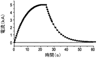
図6は、本発明の好ましい一態様による励磁パルスを表している。パルスは約20秒すると概ね5kAの最大電流に到達する。この最大電流は、約5秒間概ね一定に保たれ、次いで概ね35秒後にゼロまで減衰する。前駆体37の磁化のためには1つまたは複数のパルスを使用することがある。
FIG. 6 illustrates an excitation pulse according to a preferred embodiment of the present invention. The pulse reaches a maximum current of approximately 5 kA after about 20 seconds. This maximum current remains approximately constant for approximately 5 seconds and then decays to zero after approximately 35 seconds. One or more pulses may be used for the magnetization of the
本発明の好ましい一態様では、前駆体37及び永久磁石材料は、CoSm、NdFeまたはRMB(ここで、Rは少なくとも1種の希土類元素を含み、かつMは少なくとも1種の遷移金属、例えばFe、Co、またはFeとCo、を含む)など任意の永久磁石材料または合金を含むことがある。永久磁石は、参照によりその全体を本明細書に組み込むものとする米国特許第6,120,620号に開示されているようなプラセオジム(Pr)に富んだRMB合金を含むことが最も好ましい。プラセオジム(Pr)に富んだRMB合金は、その希土類含有量が50原子百分率を超えるプラセオジムと、セリウム、ランタン、イットリウム及びこれらの混合物からなる群より選択されたある有効量の軽希土類元素と、残りのネオジムとからなるような約13〜約19原子百分率(好ましくは約15〜約17原子百分率)の希土類元素;約4〜約20原子百分率のホウ素;並びに不純物を伴ったり伴わなかったりする残部の鉄を含む。本明細書で使用する場合、「プラセオジムに富んだ(praseodymium−rich)」という言い回しは、その鉄/ホウ素/希土類合金の希土類含有量がプラセオジムを50%を超えて含むことを意味している。本発明の別の好ましい態様では、希土類含有量のうちのプラセオジム百分率は、少なくとも70%であり、かつ総希土類含有量内に存在する軽希土類元素の有効量に応じて100%まで高めることができる。軽希土類元素の有効量とは、29MGOe(BH)max及び6kOe固有保磁度(Hci)に等しいかこれらを超えるような磁気特性で動作可能とさせるために磁化させた鉄/ホウ素/希土類合金の総希土類含有量内に存在させる量である。Mは、鉄以外に、チタン、ニッケル、ビスマス、コバルト、バナジウム、ニオブ、タンタル、クロム、モリブデン、タングステン、マンガン、アルミニウム、ゲルマニウム、すず、ジルコニウム、ハフニウム、及びこれらの混合物(ただし、これらに限らない)などの別の元素を含むことがある。したがって、この永久磁石材料は、13〜19原子百分率のR、4〜20原子百分率のB、並びに残部M(ここで、Rは、Prを50原子百分率以上、Ce、Y及びLaの少なくとも1種を0.1〜10原子百分率、及び残部のNdを含む)を含むことが最も好ましい。前駆体37及び永久磁石本体は、参照により本明細書に組み込むものとする米国特許第6,525,634号に記載されているような階段状の撮像表面を形成している複数のブロックを備えることが好ましい。
In a preferred embodiment of the present invention, the
本発明の別の好ましい態様において、本発明者らはイメージング・システム内にある永久磁石の磁化は磁化させた後に永久磁石に反跳パルスを印加することによって安定化させることができることを発見した。すなわち、最初のパルスの後で、大きさがより小さくかつ方向が反対の第2のパルスを前駆体に印加している。 In another preferred embodiment of the invention, the inventors have discovered that the magnetization of a permanent magnet in an imaging system can be stabilized by applying a recoil pulse to the permanent magnet after it has been magnetized. That is, after the first pulse, a second pulse of smaller magnitude and opposite direction is applied to the precursor.
本発明の別の好ましい態様において、本発明者らは室温を超える温度で前駆体を磁化することによって、磁化に必要なエネルギーを低減させることができることを発見した。前駆体37は、40〜200℃など室温を超えておりかつ永久磁石材料のキュリー温度未満であるような温度に加熱することが好ましい。
In another preferred embodiment of the present invention, the inventors have discovered that the energy required for magnetization can be reduced by magnetizing the precursor at a temperature above room temperature. The
本明細書では、好ましい実施形態は例示を目的として列挙している。しかし、この記述は本発明の範囲に対する限定と見なすべきではない。したがって、当業者であれば特許請求した発明の構想の趣旨を逸脱することなく、様々な修正形態、適応形態、及び代替形態を生じさせることができる。
In the present specification, preferred embodiments are listed for illustrative purposes. However, this description should not be construed as a limitation on the scope of the invention. Accordingly, various modifications, adaptations, and alternatives may occur to those skilled in the art without departing from the spirit of the claimed invention.
1 ソレノイド・コイル
2 ローラ
3 銅製シート
5 絶縁シート
7 開始リード
9 終点リード
11 ハウジング
13 空洞
15 ギャップ
17 冷却剤入力リザーバ部分
19 冷却剤入力ポート
21 微小チャンネル
23 ハウジングの底部壁
24 底部フランジ
25 内側壁
26 出力ポート
27 ハウジングの上部壁
29 外側壁
30 絶縁材料
33 開口
35 溝
37 前駆体
39 継鉄
41 抵抗器
42 インピーダンス
43 電流計
45 コンデンサ
47 ダイオード
49 電源
51 切り替え機構
100 励磁コイル・ユニット
200 励磁アセンブリ
DESCRIPTION OF
Claims (6)
前記ハウジング(11)は、該ハウジングの底部内の冷却剤入力ポート(19)と、前記冷却剤入力ポート内の複数の微小チャンネル(21)と、該ハウジングの上部内に配置させた冷却剤出力ポート(26)と、前記冷却剤出力ポート内の複数の微小チャンネルと、を含み、
前記複数の励磁コイル・ユニット(100)は互いの上に重ね合わせられており、
前記ハウジング(11)の上部(27)又は底部(23)は開口(33)又は突起部(31)を含み、
前記開口(33)は溝(35)を含み、前記突起部(31)は舌部を含み、
あるコイル・ユニット(100)の前記ハウジング(11)の前記突起部(31)は、前記アセンブリ(200)の他のコイル・ユニット(100)の前記ハウジング(11)の前記開口(33)に適合する励磁アセンブリ(200)。 An excitation assembly (200) comprising a plurality of excitation coil units (100) each comprising a coiled copper sheet (3) disposed in a housing (11),
The housing (11) includes a coolant input port (19) in the bottom of the housing, a plurality of microchannels (21) in the coolant input port, and a coolant output disposed within the top of the housing. a port (26), a plurality of micro-channels in the coolant output port, only including,
The plurality of exciting coil units (100) are superimposed on each other,
The top (27) or bottom (23) of the housing (11) includes an opening (33) or a protrusion (31),
The opening (33) includes a groove (35), the protrusion (31) includes a tongue,
The protrusion (31) of the housing (11) of one coil unit (100) fits into the opening (33) of the housing (11) of another coil unit (100) of the assembly (200). exciting assembly (200).
前記コイル状銅製シート(3)の幅が前記ソレノイド(1)の高さと実質的に等しいこと、
前記コイル状銅製シートはジョイントを全く含まないこと、
前記コイル状銅製シートはパンケーキ形に巻き付けられていること、
を特徴とする請求項2に記載の励磁アセンブリ(200)。 The coiled metal sheet (3) contains copper,
The width of the coiled copper sheet (3) is substantially equal to the height of the solenoid (1);
The coiled copper sheet does not include any joints;
The coiled copper sheet is wound in a pancake shape,
The excitation assembly (200) of claim 2 , wherein:
Applications Claiming Priority (1)
| Application Number | Priority Date | Filing Date | Title |
|---|---|---|---|
| US10/674,495 US7218195B2 (en) | 2003-10-01 | 2003-10-01 | Method and apparatus for magnetizing a permanent magnet |
Publications (3)
| Publication Number | Publication Date |
|---|---|
| JP2005111264A JP2005111264A (en) | 2005-04-28 |
| JP2005111264A5 JP2005111264A5 (en) | 2009-11-12 |
| JP4559176B2 true JP4559176B2 (en) | 2010-10-06 |
Family
ID=34393505
Family Applications (1)
| Application Number | Title | Priority Date | Filing Date |
|---|---|---|---|
| JP2004285613A Expired - Fee Related JP4559176B2 (en) | 2003-10-01 | 2004-09-30 | Method and apparatus for magnetizing a permanent magnet |
Country Status (4)
| Country | Link |
|---|---|
| US (2) | US7218195B2 (en) |
| JP (1) | JP4559176B2 (en) |
| CN (2) | CN101800111B (en) |
| IT (1) | ITMI20041681A1 (en) |
Families Citing this family (10)
| Publication number | Priority date | Publication date | Assignee | Title |
|---|---|---|---|---|
| GB2422905B (en) * | 2005-02-04 | 2007-02-14 | Siemens Magnet Technology Ltd | Material for electrical isolation and vibro-acoustic performance |
| US7710081B2 (en) | 2006-10-27 | 2010-05-04 | Direct Drive Systems, Inc. | Electromechanical energy conversion systems |
| JP4512855B2 (en) * | 2007-04-16 | 2010-07-28 | 日本電磁測器株式会社 | Magnetizer |
| CN101071672B (en) * | 2007-04-17 | 2011-05-11 | 安泰科技股份有限公司 | Magnetizing method for batch small sintered Nd-Fe-B magnet |
| CN101388271A (en) * | 2007-09-14 | 2009-03-18 | Ge医疗系统环球技术有限公司 | Magnetic body system and MRI equipment |
| US8310123B2 (en) | 2008-07-28 | 2012-11-13 | Direct Drive Systems, Inc. | Wrapped rotor sleeve for an electric machine |
| CN104677723B (en) * | 2015-01-30 | 2017-06-13 | 西北工业大学 | The main coil of electromagnetic type stress wave producer and the method for charge/discharge |
| IT201600117005A1 (en) * | 2016-11-18 | 2018-05-18 | Laboratorio Elettrofisico Eng S R L | QUICK-PULSE MAGNETIZED EQUIPMENT |
| JP2020028185A (en) * | 2018-08-10 | 2020-02-20 | Tdk株式会社 | Magnet structure, manufacturing method of magnet structure, and manufacturing method of rotating electric machine |
| CN110136919B (en) * | 2019-06-11 | 2024-01-30 | 宁波兴隆磁性技术有限公司 | Axial multipole magnetizing apparatus |
Citations (5)
| Publication number | Priority date | Publication date | Assignee | Title |
|---|---|---|---|---|
| US3056071A (en) * | 1959-02-12 | 1962-09-25 | William R Baker | Electrical coil structure |
| JPS63274121A (en) * | 1987-05-02 | 1988-11-11 | Shinko Electric Co Ltd | Mechanism for cooling coil |
| US4896130A (en) * | 1987-11-16 | 1990-01-23 | Ermilov Igor V | Magnetic system |
| JPH10326710A (en) * | 1997-03-28 | 1998-12-08 | Seiko Epson Corp | Magnetizing method and device of large-sized magnet |
| US6525634B2 (en) * | 2001-04-03 | 2003-02-25 | General Electric Company | Permanent magnet assembly and method of making thereof |
Family Cites Families (29)
| Publication number | Priority date | Publication date | Assignee | Title |
|---|---|---|---|---|
| US3363207A (en) * | 1966-09-19 | 1968-01-09 | Atomic Energy Commission Usa | Combined insulating and cryogen circulating means for a superconductive solenoid |
| US3626587A (en) * | 1970-04-06 | 1971-12-14 | Westinghouse Electric Corp | Methods of constructing electrical transformers |
| US3899762A (en) | 1974-10-03 | 1975-08-12 | Permag Magnetics Corp | Permanent magnetic structure |
| US4039990A (en) * | 1975-10-01 | 1977-08-02 | General Electric Company | Sheet-wound, high-voltage coils |
| US4496395A (en) | 1981-06-16 | 1985-01-29 | General Motors Corporation | High coercivity rare earth-iron magnets |
| US4540453A (en) | 1982-10-28 | 1985-09-10 | At&T Technologies | Magnetically soft ferritic Fe-Cr-Ni alloys |
| JPH03170643A (en) | 1983-08-04 | 1991-07-24 | Sumitomo Special Metals Co Ltd | Alloy for permanent magnet |
| US4827235A (en) | 1986-07-18 | 1989-05-02 | Kabushiki Kaisha Toshiba | Magnetic field generator useful for a magnetic resonance imaging instrument |
| JPS63241905A (en) | 1987-03-27 | 1988-10-07 | Sumitomo Special Metals Co Ltd | Magnetic field generating equipment |
| JPH02141501A (en) | 1988-11-22 | 1990-05-30 | Tdk Corp | Alloy powder for permanent magnet |
| US5252924A (en) | 1991-11-18 | 1993-10-12 | Sumitomo Special Metals Co., Ltd. | Magnetic field generating apparatus for MRI |
| JP2808198B2 (en) | 1990-07-02 | 1998-10-08 | 住友特殊金属株式会社 | Magnetic field generator for MRI and its manufacturing method |
| DE69129687T2 (en) | 1990-09-29 | 1999-03-11 | Sumitomo Spec Metals | Device for generating a magnetic field for imaging by means of magnetic resonance |
| JP2816256B2 (en) | 1991-03-25 | 1998-10-27 | 株式会社日立製作所 | Coil body |
| ATE167239T1 (en) | 1992-02-15 | 1998-06-15 | Santoku Metal Ind | ALLOY BLOCK FOR A PERMANENT MAGNET, ANISOTROPIC POWDER FOR A PERMANENT MAGNET, METHOD FOR PRODUCING THE SAME AND PERMANENT MAGNET |
| FR2704975B1 (en) | 1993-05-03 | 1995-06-23 | Commissariat Energie Atomique | Permanent magnet structure for the production of a stable and homogeneous magnetic induction in a given volume. |
| EP0645641B1 (en) | 1993-09-29 | 1999-06-16 | Oxford Magnet Technology Limited | Improvements in or relating to MRI magnets |
| EP0671800B1 (en) * | 1993-09-29 | 1998-06-17 | Denso Corporation | Field coil for motor and method of producing said field coil |
| JPH0831635A (en) | 1994-07-08 | 1996-02-02 | Sumitomo Special Metals Co Ltd | Mri magnetic field generating device |
| US5721397A (en) * | 1995-06-07 | 1998-02-24 | Weinberg; Martin J. | Electrical insulation and products protected thereby |
| US5900793A (en) | 1997-07-23 | 1999-05-04 | Odin Technologies Ltd | Permanent magnet assemblies for use in medical applications |
| JPH10174681A (en) | 1996-12-17 | 1998-06-30 | Shin Etsu Chem Co Ltd | Magnetic circuit of permanent magnet |
| WO1999015914A1 (en) | 1997-09-25 | 1999-04-01 | Odin Technologies Ltd. | Magnetic apparatus for mri |
| US6255670B1 (en) | 1998-02-06 | 2001-07-03 | General Electric Company | Phosphors for light generation from light emitting semiconductors |
| US6259252B1 (en) | 1998-11-24 | 2001-07-10 | General Electric Company | Laminate tile pole piece for an MRI, a method manufacturing the pole piece and a mold bonding pole piece tiles |
| CN1251252C (en) | 1999-02-12 | 2006-04-12 | 通用电气公司 | Iron-boron-rare earth type pemanent magnetic material containing cerium, neodymium and/or praseodymium and its production method |
| US6120620A (en) | 1999-02-12 | 2000-09-19 | General Electric Company | Praseodymium-rich iron-boron-rare earth composition, permanent magnet produced therefrom, and method of making |
| DE10109105C2 (en) * | 2001-02-24 | 2003-01-09 | Mfh Hyperthermiesysteme Gmbh | Magnetic coil arrangement of a magnetic field applicator for heating magnetic or magnetizable substances or solids in biological tissue |
| JP2002286050A (en) * | 2001-03-22 | 2002-10-03 | Mitsubishi Electric Corp | Electromagnetic coil device and manufacturing method thereof |
-
2003
- 2003-10-01 US US10/674,495 patent/US7218195B2/en not_active Expired - Fee Related
-
2004
- 2004-08-31 IT IT001681A patent/ITMI20041681A1/en unknown
- 2004-09-27 CN CN201010155315.5A patent/CN101800111B/en not_active Expired - Fee Related
- 2004-09-27 CN CN200410082687.4A patent/CN1604242B/en not_active Expired - Fee Related
- 2004-09-30 JP JP2004285613A patent/JP4559176B2/en not_active Expired - Fee Related
-
2006
- 2006-11-20 US US11/601,922 patent/US8468684B2/en not_active Expired - Fee Related
Patent Citations (5)
| Publication number | Priority date | Publication date | Assignee | Title |
|---|---|---|---|---|
| US3056071A (en) * | 1959-02-12 | 1962-09-25 | William R Baker | Electrical coil structure |
| JPS63274121A (en) * | 1987-05-02 | 1988-11-11 | Shinko Electric Co Ltd | Mechanism for cooling coil |
| US4896130A (en) * | 1987-11-16 | 1990-01-23 | Ermilov Igor V | Magnetic system |
| JPH10326710A (en) * | 1997-03-28 | 1998-12-08 | Seiko Epson Corp | Magnetizing method and device of large-sized magnet |
| US6525634B2 (en) * | 2001-04-03 | 2003-02-25 | General Electric Company | Permanent magnet assembly and method of making thereof |
Also Published As
| Publication number | Publication date |
|---|---|
| ITMI20041681A1 (en) | 2004-11-30 |
| US20070063800A1 (en) | 2007-03-22 |
| US7218195B2 (en) | 2007-05-15 |
| CN1604242B (en) | 2010-08-11 |
| CN1604242A (en) | 2005-04-06 |
| CN101800111A (en) | 2010-08-11 |
| US8468684B2 (en) | 2013-06-25 |
| JP2005111264A (en) | 2005-04-28 |
| US20050073383A1 (en) | 2005-04-07 |
| CN101800111B (en) | 2012-12-12 |
Similar Documents
| Publication | Publication Date | Title |
|---|---|---|
| US8468684B2 (en) | Method and apparatus for magnetizing a permanent magnet | |
| JP3548240B2 (en) | Magnetic resonance imaging (MRI) magnet | |
| US7345560B2 (en) | Method and apparatus for magnetizing a permanent magnet | |
| US10712411B2 (en) | Bulk magnet structure and bulk magnet system for NMR | |
| WO2001078088A1 (en) | Bulk amorphous metal magnetic component | |
| JP6296745B2 (en) | Magnetization method of rare earth magnet and rare earth magnet | |
| WO2017169110A1 (en) | Superconducting magnet device and energizing method for same | |
| US20160365183A1 (en) | Superconducting magnet | |
| US7183766B2 (en) | Superconducting magnetic field generation apparatus and sputter coating apparatus | |
| JPS6076110A (en) | Assembling and magnetizing method for magnetic circuit | |
| GB2282451A (en) | Yoke MRI magnet with radially laminated pole-plates | |
| JP3150507B2 (en) | Superconducting magnet device | |
| JP2009043759A (en) | Superconducting electromagnet | |
| JP3598237B2 (en) | Superconducting magnet device and method of magnetizing superconductor | |
| JP4219761B2 (en) | Magnetic field generator and driving method thereof | |
| US10547218B2 (en) | Variable magnetic monopole field electro-magnet and inductor | |
| JP2003022919A (en) | Magnetic element | |
| JP2011114990A (en) | Isotropic film magnet laminated micro rotary electric machine | |
| JP2002043140A (en) | Magnetic element | |
| JPH11265816A (en) | Superconducting device | |
| JPH07272930A (en) | Magnetizer and its magnetizing method | |
| JPH05267054A (en) | High magnetic field generator and permanent electric current switch | |
| JPH0199465A (en) | Controlling motor | |
| JPS61292303A (en) | Magnetizing method for permanent magnet | |
| JPH099600A (en) | Actuator for magnetic disk device |
Legal Events
| Date | Code | Title | Description |
|---|---|---|---|
| A621 | Written request for application examination |
Free format text: JAPANESE INTERMEDIATE CODE: A621 Effective date: 20070927 |
|
| A521 | Request for written amendment filed |
Free format text: JAPANESE INTERMEDIATE CODE: A523 Effective date: 20090928 |
|
| RD02 | Notification of acceptance of power of attorney |
Free format text: JAPANESE INTERMEDIATE CODE: A7422 Effective date: 20090928 |
|
| RD04 | Notification of resignation of power of attorney |
Free format text: JAPANESE INTERMEDIATE CODE: A7424 Effective date: 20090928 |
|
| TRDD | Decision of grant or rejection written | ||
| A01 | Written decision to grant a patent or to grant a registration (utility model) |
Free format text: JAPANESE INTERMEDIATE CODE: A01 Effective date: 20100629 |
|
| A977 | Report on retrieval |
Free format text: JAPANESE INTERMEDIATE CODE: A971007 Effective date: 20100630 |
|
| A01 | Written decision to grant a patent or to grant a registration (utility model) |
Free format text: JAPANESE INTERMEDIATE CODE: A01 |
|
| A61 | First payment of annual fees (during grant procedure) |
Free format text: JAPANESE INTERMEDIATE CODE: A61 Effective date: 20100722 |
|
| R150 | Certificate of patent or registration of utility model |
Free format text: JAPANESE INTERMEDIATE CODE: R150 |
|
| FPAY | Renewal fee payment (event date is renewal date of database) |
Free format text: PAYMENT UNTIL: 20130730 Year of fee payment: 3 |
|
| R250 | Receipt of annual fees |
Free format text: JAPANESE INTERMEDIATE CODE: R250 |
|
| R250 | Receipt of annual fees |
Free format text: JAPANESE INTERMEDIATE CODE: R250 |
|
| R250 | Receipt of annual fees |
Free format text: JAPANESE INTERMEDIATE CODE: R250 |
|
| R250 | Receipt of annual fees |
Free format text: JAPANESE INTERMEDIATE CODE: R250 |
|
| LAPS | Cancellation because of no payment of annual fees |