JP4559036B2 - Imaging array and manufacturing method thereof - Google Patents
Imaging array and manufacturing method thereof Download PDFInfo
- Publication number
- JP4559036B2 JP4559036B2 JP2003098711A JP2003098711A JP4559036B2 JP 4559036 B2 JP4559036 B2 JP 4559036B2 JP 2003098711 A JP2003098711 A JP 2003098711A JP 2003098711 A JP2003098711 A JP 2003098711A JP 4559036 B2 JP4559036 B2 JP 4559036B2
- Authority
- JP
- Japan
- Prior art keywords
- layer
- capacitor
- tft
- electrode
- dielectric layer
- Prior art date
- Legal status (The legal status is an assumption and is not a legal conclusion. Google has not performed a legal analysis and makes no representation as to the accuracy of the status listed.)
- Expired - Fee Related
Links
- 238000004519 manufacturing process Methods 0.000 title description 21
- 238000003384 imaging method Methods 0.000 title description 9
- 239000003990 capacitor Substances 0.000 claims description 72
- 239000004065 semiconductor Substances 0.000 claims description 48
- 229910021417 amorphous silicon Inorganic materials 0.000 claims description 45
- 230000005855 radiation Effects 0.000 claims description 30
- 239000000463 material Substances 0.000 claims description 26
- 229910052751 metal Inorganic materials 0.000 claims description 25
- 239000002184 metal Substances 0.000 claims description 25
- 239000000758 substrate Substances 0.000 claims description 12
- 239000011651 chromium Substances 0.000 claims description 7
- 239000012535 impurity Substances 0.000 claims description 7
- VYZAMTAEIAYCRO-UHFFFAOYSA-N Chromium Chemical compound [Cr] VYZAMTAEIAYCRO-UHFFFAOYSA-N 0.000 claims description 5
- 229910052804 chromium Inorganic materials 0.000 claims description 4
- OFIYHXOOOISSDN-UHFFFAOYSA-N tellanylidenegallium Chemical compound [Te]=[Ga] OFIYHXOOOISSDN-UHFFFAOYSA-N 0.000 claims description 4
- 239000010409 thin film Substances 0.000 claims description 3
- 230000003287 optical effect Effects 0.000 claims description 2
- 238000002161 passivation Methods 0.000 description 16
- 238000000034 method Methods 0.000 description 14
- 230000008569 process Effects 0.000 description 8
- 238000003860 storage Methods 0.000 description 8
- 238000000623 plasma-assisted chemical vapour deposition Methods 0.000 description 6
- XYFCBTPGUUZFHI-UHFFFAOYSA-N Phosphine Chemical compound P XYFCBTPGUUZFHI-UHFFFAOYSA-N 0.000 description 4
- 238000003491 array Methods 0.000 description 4
- 230000000903 blocking effect Effects 0.000 description 4
- 238000001465 metallisation Methods 0.000 description 4
- 238000007740 vapor deposition Methods 0.000 description 4
- ZOKXTWBITQBERF-UHFFFAOYSA-N Molybdenum Chemical compound [Mo] ZOKXTWBITQBERF-UHFFFAOYSA-N 0.000 description 3
- XUIMIQQOPSSXEZ-UHFFFAOYSA-N Silicon Chemical compound [Si] XUIMIQQOPSSXEZ-UHFFFAOYSA-N 0.000 description 3
- 229910052782 aluminium Inorganic materials 0.000 description 3
- XAGFODPZIPBFFR-UHFFFAOYSA-N aluminium Chemical compound [Al] XAGFODPZIPBFFR-UHFFFAOYSA-N 0.000 description 3
- 239000004020 conductor Substances 0.000 description 3
- 238000000151 deposition Methods 0.000 description 3
- 238000010586 diagram Methods 0.000 description 3
- 239000002019 doping agent Substances 0.000 description 3
- 238000005530 etching Methods 0.000 description 3
- 230000000873 masking effect Effects 0.000 description 3
- 239000007769 metal material Substances 0.000 description 3
- 229910052750 molybdenum Inorganic materials 0.000 description 3
- 239000011733 molybdenum Substances 0.000 description 3
- 238000000059 patterning Methods 0.000 description 3
- 229920002120 photoresistant polymer Polymers 0.000 description 3
- 229910052710 silicon Inorganic materials 0.000 description 3
- 239000010703 silicon Substances 0.000 description 3
- 229910052581 Si3N4 Inorganic materials 0.000 description 2
- 230000004888 barrier function Effects 0.000 description 2
- AMGQUBHHOARCQH-UHFFFAOYSA-N indium;oxotin Chemical compound [In].[Sn]=O AMGQUBHHOARCQH-UHFFFAOYSA-N 0.000 description 2
- 238000002347 injection Methods 0.000 description 2
- 239000007924 injection Substances 0.000 description 2
- 229910000073 phosphorus hydride Inorganic materials 0.000 description 2
- HQVNEWCFYHHQES-UHFFFAOYSA-N silicon nitride Chemical compound N12[Si]34N5[Si]62N3[Si]51N64 HQVNEWCFYHHQES-UHFFFAOYSA-N 0.000 description 2
- 238000004544 sputter deposition Methods 0.000 description 2
- VYPSYNLAJGMNEJ-UHFFFAOYSA-N Silicium dioxide Chemical compound O=[Si]=O VYPSYNLAJGMNEJ-UHFFFAOYSA-N 0.000 description 1
- 230000002238 attenuated effect Effects 0.000 description 1
- XQPRBTXUXXVTKB-UHFFFAOYSA-M caesium iodide Chemical compound [I-].[Cs+] XQPRBTXUXXVTKB-UHFFFAOYSA-M 0.000 description 1
- 239000002800 charge carrier Substances 0.000 description 1
- 238000004140 cleaning Methods 0.000 description 1
- 230000008021 deposition Effects 0.000 description 1
- 238000002059 diagnostic imaging Methods 0.000 description 1
- 230000000694 effects Effects 0.000 description 1
- 230000002349 favourable effect Effects 0.000 description 1
- 230000004907 flux Effects 0.000 description 1
- BHEPBYXIRTUNPN-UHFFFAOYSA-N hydridophosphorus(.) (triplet) Chemical compound [PH] BHEPBYXIRTUNPN-UHFFFAOYSA-N 0.000 description 1
- 239000011810 insulating material Substances 0.000 description 1
- 230000004048 modification Effects 0.000 description 1
- 238000012986 modification Methods 0.000 description 1
- 230000000149 penetrating effect Effects 0.000 description 1
- 238000000206 photolithography Methods 0.000 description 1
- 230000007261 regionalization Effects 0.000 description 1
- 230000008439 repair process Effects 0.000 description 1
- 230000004044 response Effects 0.000 description 1
- 229910052814 silicon oxide Inorganic materials 0.000 description 1
- 239000000126 substance Substances 0.000 description 1
Images


Classifications
-
- H—ELECTRICITY
- H01—ELECTRIC ELEMENTS
- H01L—SEMICONDUCTOR DEVICES NOT COVERED BY CLASS H10
- H01L27/00—Devices consisting of a plurality of semiconductor or other solid-state components formed in or on a common substrate
- H01L27/14—Devices consisting of a plurality of semiconductor or other solid-state components formed in or on a common substrate including semiconductor components sensitive to infrared radiation, light, electromagnetic radiation of shorter wavelength or corpuscular radiation and specially adapted either for the conversion of the energy of such radiation into electrical energy or for the control of electrical energy by such radiation
- H01L27/144—Devices controlled by radiation
- H01L27/146—Imager structures
- H01L27/14643—Photodiode arrays; MOS imagers
- H01L27/14658—X-ray, gamma-ray or corpuscular radiation imagers
-
- H—ELECTRICITY
- H01—ELECTRIC ELEMENTS
- H01L—SEMICONDUCTOR DEVICES NOT COVERED BY CLASS H10
- H01L27/00—Devices consisting of a plurality of semiconductor or other solid-state components formed in or on a common substrate
- H01L27/14—Devices consisting of a plurality of semiconductor or other solid-state components formed in or on a common substrate including semiconductor components sensitive to infrared radiation, light, electromagnetic radiation of shorter wavelength or corpuscular radiation and specially adapted either for the conversion of the energy of such radiation into electrical energy or for the control of electrical energy by such radiation
- H01L27/144—Devices controlled by radiation
- H01L27/146—Imager structures
- H01L27/14643—Photodiode arrays; MOS imagers
Landscapes
- Engineering & Computer Science (AREA)
- Power Engineering (AREA)
- Physics & Mathematics (AREA)
- General Physics & Mathematics (AREA)
- Electromagnetism (AREA)
- Condensed Matter Physics & Semiconductors (AREA)
- Computer Hardware Design (AREA)
- Microelectronics & Electronic Packaging (AREA)
- Health & Medical Sciences (AREA)
- Toxicology (AREA)
- Solid State Image Pick-Up Elements (AREA)
- Transforming Light Signals Into Electric Signals (AREA)
- Thin Film Transistor (AREA)
Description
【0001】
【発明の属する技術分野】
本発明は一般に撮影アレイに関し、特に撮影アレイの画素構造に関する。
【0002】
【発明の背景】
撮影アレイは、通常、シンチレーション媒体に結合されたフォトセンサアレイを含む。シンチレータで吸収された放射線は光学光子を発生し、それらの光子がフォトダイオードなどのフォトセンサに入射する。光子はフォトセンサで吸収され、入射光子束に対応する電気信号が発生される。フォトセンサの製造においては、a−Si:Hの光電特性が好都合であり且つフォトセンサなどのデバイスを製造するのが相対的に容易であるという理由により、一般に水素化アモルファスシリコン(a−Si:H)が使用されている。具体的には、フォトダイオードなどの感光素子を薄膜トランジスタ(TFT)などの必要な制御素子又はスイッチング素子と関連させて相対的に大きなアレイとして形成することができる。放射線検出器及びディスプレイアレイは、通常、大きな基板の上に製造され、基板上にはTFT、アドレス線、コンデンサ、及びフォトセンサなどのデバイスのような多数の構成要素が導電性材料、半導体材料及び絶縁材料の蒸着及びパターン形成によって形成される。
【0003】
そのようなTFTアレイを製造するための少なくとも1つの周知の方法は、通常、ボトムゲートTFTと、データアドレス線及び走査アドレス線とを製造することを含む。周知のいくつかのボトムゲートTFTにおいては、ボトムゲート金属がチャネル領域を遮蔽している。すなわち、ボトムゲート金属はバックライトからの光を阻止する光阻止素子として作用する。光子はTFTに望ましくない漏れを発生させる可能性があるため、光阻止層を設けることが望ましい。例えば、デジタルX線パネルでは、光はデバイスの上面に蒸着されたシンチレータから発生され、従って、TFT領域は光子に直接さらされる。従って、TFTチャネル領域を望ましくない光から遮蔽するために、追加のフォトリソグラフィレベルを必要とする追加の光阻止層が必要である。
【特許文献1】
米国特許第6462802号
【0004】
【発明の概要】
1つの面においては、放射線検出器が提供される。放射線検出器は、ソース電極と、ドレイン電極と、ゲート電極と、TFT誘電体層と、TFT半導体層と、TFT真性アモルファスシリコン(a−Si)層とを含むトップゲート薄膜トランジスタ(TFT)を含む。放射線検出器は、第1の電極と、ゲート電極とほぼ共面である第2の電極と、コンデンサ誘電体とを含むコンデンサを更に含み、コンデンサ誘電体は、TFT誘電体層とほぼ共面であるコンデンサ誘電体層と、TFT半導体層とほぼ共面であるコンデンサ半導体層と、TFTa−Si層とほぼ共面であるコンデンサa−Si層とを含む。
【0005】
別の面においては、放射線検出器を製造する方法が提供される。方法は、ソース電極と、ドレイン電極と、ゲート電極と、TFT誘電体層と、TFT半導体層と、a−Si層とを含むトップゲート薄膜トランジスタ(TFT)を形成することと、第1の電極と、ゲート電極とほぼ共面である第2の電極と、コンデンサ誘電体とを含み、コンデンサ誘電体はTFT誘電体層とほぼ共面であるコンデンサ誘電体層と、TFT半導体層とほぼ共面であるコンデンサ半導体層と、TFTa−Si層とほぼ共面であるコンデンサa−Si層とを具備するようなコンデンサを形成することとを含む。
【0006】
更に別の面においては、放射線源と、放射線検出器とを含む撮影システムが提供される。放射線検出器は、ソース電極と、ドレイン電極と、ゲート電極と、TFT誘電体層と、TFT半導体層と、TFT真性アモルファスシリコン(a−Si)層とを含むトップゲート薄膜トランジスタ(TFT)を含む。放射線検出器は、第1の電極と、ゲート電極とほぼ共面である第2の電極と、コンデンサ誘電体とを含むコンデンサを更に含み、コンデンサ誘電体は、TFT誘電体層とほぼ共面であるコンデンサ誘電体層と、TFT半導体層とほぼ共面であるコンデンサ半導体層と、TFTa−Si層とほぼ共面であるコンデンサa−Si層とを含む。
【0007】
更に別の面においては、放射線検出器を製造する方法が提供される。方法は、コンデンサの第2の電極とゲート電極を1回の処理工程で形成することと、コンデンサ誘電体とTFT誘電体層を1回の処理工程で形成することと、コンデンサ半導体層とTFT半導体層を1回の処理工程で形成することとを含む。
【0008】
【発明の実施の形態】
図1は、撮影システム10の概略図である。一実施例では、撮影システム10は、以下に説明する放射線検出器が組み込まれた、ウィスコンシン州ミルウォーキーのGeneral Electric CorporationのGE Medical Systemsビジネスから市販されているSennovision 2000D(商標)などの医療用撮影システムであるが、それには限定されない。撮影システム10は、円錐形ビームを投射する放射線源12を含む。一実施例においては、放射線源12はX線源12であり、円錐形ビームはX線ビームである。X線ビームは物体14、すなわち、患者などの撮影されるべき物体を通過する。X線ビームは物体14により減衰された後に、放射線検出器16に入射する。
【0009】
図2は、撮影システム10(図1に示す)と共に使用できる放射線検出器18を示す。放射線検出器18は基板20を含み、基板20の上に画素アレイ22(フォトセンサアレイと呼ばれることもある)が配置されている。フォトセンサアレイ22はコンデンサ24、フォトダイオード26及びTFTなどのスイッチングデバイス28のような複数の電子素子を含む。TFT28は画素アレイ22の上に配置され、対応する1つのコンデンサ24と1つのフォトダイオード26を対応するデータ線30に選択的に結合する。フォトセンサアレイ22は、複数の個別の画素34をアドレス指定するための複数の走査線32を更に含む。データ線30は画素アレイ22の第1の軸36に沿って方向を定められており、走査線32は画素アレイ22の第2の軸38に沿って方向を定められている。画素アレイ22の第1の軸36と第2の軸38は互いにほぼ垂直に配置されている。
【0010】
図2では、図面をわかりやすくするために、フォトセンサアレイ22に沿って延出するデータ線30、走査線32及び共通線40は数本ずつしか示されていない。データ線30、走査線32及び共通線40は、フォトセンサアレイ22の個々の画素34を1本のデータ線30、1本の走査線32及び1本の共通線40によりアドレス指定可能であるように、行と列を成して配列されている。一実施例では、データ線30、走査線32及び共通線40はモリブデン、クロム及び/又はアルミニウムなどの導電性材料を含む。コンデンサ24はフォトダイオード26に電気的に接触し、TFT28を介してデータ線30に電気的に結合されている。フォトダイオード26は、入射する光子に応答して、検出された入射光に対応する電気信号を発生するアレイ22の活性部分を含む。X線エネルギーは、フォトダイオード26の表面付近に配置されたヨウ化セシウムなどの蛍光物質の層(図示せず)を通過することにより、可視光エネルギーに変換される。コンデンサ24はフォトダイオード26で発生された電荷を蓄積し、走査線32がアドレス指定されたときに、蓄積されたこの電荷をTFT28を介して放電する。
【0011】
図3は、基板20の上に形成された画素34の一部の横断面図である。一実施例では、ここで説明する全ての半導体層及び誘電体層はプラズマ化学気相成長(PECVD)により蒸着される。画素34は、基板20の表面全体に延在する第1の金属層56から形成されるソース電極50、ドレイン電極52及び第1のコンデンサ電極54を含む。第1の金属層56は、ドレイン電極52とデータ線30(図2に示す)が一体に形成され、且つソース電極50、ドレイン電極52及び第1のコンデンサ電極54がほぼ等しい厚さになるように形成される。ソース電極50とドレイン電極52の上及びその間と、第1のコンデンサ電極54の上及びそれに隣接する領域にn型不純物添加真性a−Si層58が形成される。ここで使用する用語「形成される」は、パターン形成、マスキング、蒸着及びエッチングを含む画素34の各素子を製造するための工程を含むが、それらには限定されない。
【0012】
a−Si層58の上及びその間と、基板20の上にTFTスタック60が形成される。ここで使用する用語「TFTスタック」は、真性アモルファスシリコンなどのTFT半導体材料層66の表面上に延在するTFT誘電体層64の表面に沿って延在するTFTゲート電極62を表す。一実施例では、ゲート電極62は走査線32(図2に示す)と一体に形成される。蓄積コンデンサ68は第1の蓄積コンデンサ電極54と、コンデンサ誘電体70と、コンデンサ誘電体層74の表面に沿って延在する第2の蓄積コンデンサ電極72とを含む。一実施例においては、コンデンサ誘電体70は、n型不純物添加真性a−Si層58の表面に沿って延在する、真性アモルファスシリコンなどのコンデンサ半導体材料層76の表面に沿って延在するコンデンサ誘電体層74を含み、a−Si層58は第1のコンデンサ電極54の表面に沿って延在すると共に、第1のコンデンサ電極54に隣接して延在している。別の実施例では、コンデンサ誘電体70は、真性アモルファスシリコンなどの半導体材料層76の表面に沿って延在するコンデンサ誘電体層74を含む。
【0013】
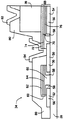
第2のコンデンサ電極72の上にダイオードスタック78が形成される。一実施例では、ダイオードスタック78はPINダイオード(図示せず)を含む。PINダイオードは、n+型材料の層の上に蒸着された真性a−Siの層の上に蒸着されるp+型材料の層を含む。ダイオードスタック78と、ゲート電極62、ソース電極50、ドレイン電極52、第2のコンデンサ電極72及び基板20の露出部分の上にパッシベーション層80が形成される。共通ビア82がダイオードスタック78に電気的に接続され且つソースビア84がソース電極50及び第2のコンデンサ電極72に電気的に接続されるように、共通ビア82とソースビア84は形成される。
【0014】
図4及び図5は、それぞれ、初期製造段階と、それに続く第1の製造段階における図3に示す画素34の一部の横断面図である。半導体層及び誘電体層はプラズマエンハンスト化学気相成長(PECVD)により蒸着される。
【0015】
一実施例では、第1の金属層56は基板20の上に1回のメタライゼーション工程により蒸着される。メタライゼーション中、金属材料はスパッタリングにより蒸着されるか、又は金属材料の薄い層を蒸着することにより蒸着される。あるいは、スパッタリング又は蒸着以外の方法により金属材料が蒸着される。第1の金属層56はアルミニウム、クロム及び/又はモリブデンを含むが、それらには限定されない。第1の金属層56は、ソース電極50、ドレイン電極52及び第1のコンデンサ電極54を露出させるためにパターン形成され且つエッチングされる。パターン形成工程はフォトレジストを蒸着させ、所望のパターンに従ってフォトレジストを露出させ、フォトレジストを処理してその複数の部分を除去し、所望の寸法に対応する選択されたパターンを有するマスクを残すことを含むが、それらには限定されない。
【0016】
一実施例では、ソース電極50、ドレイン電極52及び第1のコンデンサ電極54の上にn型不純物添加a−Si層58が蒸着される。ほぼ真性のa−Si半導体材料層66(図3に示す)を蒸着させる前に、n型不純物添加a−Si層58をパターン形成し且つエッチングする。n型不純物添加a−Si層58は半導体材料層66への所望の電子注入を促進すると共に、望ましくないホール注入を抑制する。一実施例では、a−Si層58の厚さは約100オングストローム(Å)から約3000Åである。別の実施例においては、a−Si層58は約400Åの厚さである。更に別の実施例では、a−Si層58は約200Åから約600Åの厚さである。
【0017】
図6及び図7は、それぞれ、第2の製造段階と、続く第3の製造段階の間の図3に示す画素34の一部の横断面図である。a−Si層58の上に半導体材料層90が蒸着される。半導体材料層90はこの時点ではエッチングされない。一実施例では、半導体材料層90の厚さは約100Åから約3000Åである。別の実施例においては、半導体材料層90は約500Åの厚さである。さらに別の実施例では、半導体材料層90は約300Åから約700Åの厚さである。半導体材料層90は真性アモルファスシリコンを含むが、それに限定されない。
【0018】
半導体材料層90の上に誘電体層92が蒸着される。誘電体層92はこの時点ではエッチングされない。一実施例では、誘電体層92の厚さは約1000Åから約4000Åである。別の実施例においては、誘電体層92は約2500Åの厚さである。さらに別の実施例では、誘電体層92は約1500Åから約3500Åの厚さである。誘電体層92はSiNを含むが、それに限定されない。
【0019】
誘電体層92の上に第2の金属層94が蒸着される。一実施例では、第2の金属層94の厚さは約500Åから約5000Åである。別の実施例においては、第2の金属層94は約2500Åの厚さである。さらに別の実施例では、第2の金属層94は約1500Åから約3500Åの厚さである。第2の金属層94はモリブデン、アルミニウム及び/又はクロムを含むが、それらには限定されない。
【0020】
第2のコンデンサ電極72の上に、パターン形成工程を行なうことなくダイオードスタック78が蒸着される。一実施例では、ダイオードスタック78はp+型層と、ほぼ真性の層と、n+型a−Si層とを含む。別の実施例においては、第4の透明導電性トップコンタクト層(図示せず)がダイオードスタック78の一部となっている。一実施例では、ダイオードトップコンタクトは酸化インジウムスズ(ITO)などの透明導体を含むが、それに限定されない。ダイオードスタック78はパターン形成され且つエッチングされる。ダイオードトップコンタクトをまずウェットエッチングするか、あるいはダイオードトップコンタクトをドライエッチングし、その後に、ダイオードスタック78をドライエッチングするときに、同じマスクを使用しても良い。あるいは、ダイオードスタック78より小さいダイオードトップコンタクトを規定するために2つの別個のマスキング工程を使用することも可能であり、その後にダイオードスタック78をパターン形成し、エッチングする。
【0021】
半導体材料層90、誘電体層92及び第2の金属層94は、TFTスタック60及び蓄積コンデンサ68の一部96を形成するためにパターン形成され、エッチングされる。エッチング工程は、第1の金属層56が接触されたときに停止する。一実施例では、TFTスタック60は、第2のコンデンサ電極72とほぼ共面であり(すなわち、同一平面上にある)且つ同じメタライゼーションから同じ処理工程で形成されるTFTゲート電極62と、コンデンサ誘電体層74とほぼ共面であり且つ同じ蒸着層から同じ処理工程で形成されるTFT誘電体層64と、半導体材料層76とほぼ共面であり且つ同じ半導体材料から同じ処理工程で形成されるTFT半導体材料層66とを含む。一実施例では、ゲート電極62は活性TFT領域から光を阻止することを容易にする。
【0022】
図8及び図9は、それぞれ、第4の製造段階と、続く第5の製造段階の間の図3に示す画素34の一部の横断面図である。製造中、画素34の全面にパッシベーション層100が蒸着される。パッシベーション層100は、ダイオードスタック78、第2のコンデンサ電極72及びソース電極50を露出させるためにエッチングされる。一実施例では、パッシベーション層100の厚さは約0.5ミクロン(μ)から約1.5μである。別の実施例においては、パッシベーション層100は約1.0μの厚さである。更に別の実施例では、パッシベーション層100は約0.8μから約1.2μの厚さである。パッシベーション層100は窒化珪素及び酸化珪素を含むが、それらには限定されない。パッシベーション層100は、これ以降の処理における機械的損傷及び化学的損傷から複数のダイオード側壁102を保護することを容易にする。パッシベーション層100はエッチングされ、画素34の上に第3の金属層104が蒸着されて、共通ビア82及びソースビア84を形成する。共通ビア82及びソースビア84は、パッシベーション層100の下方に位置する素子に対して電気的接触を成立させることができるようにパッシベーション層100の一部を貫通する孔を設けるために1回のエッチング工程で形成される(すなわち、共通ビア82及びソースビア84は全ての側面で共通するパッシベーション層100の残りの部分により包囲されている)。最後に、アレイ18(図2に示す)の1つの縁部で走査線32(図2に示す)、共通線40(図2に示す)及びデータ線30(図2に示す)に対するコンタクトパッドを露出させるために、画素34の上にバリア誘電体層(図示せず)が蒸着され、パターン形成され、エッチングされる。バリア誘電体層は窒化珪素を含んでいて良いが、それには限定されない。
【0023】
図10は、放射線検出器の画素34の一部の別の実施例の横断面図である。半導体層及び誘電体層はプラズマエンハンスト化学気相成長(PECVD)により蒸着される。一実施例では、基板202の上に1回のマスキング工程により酸化インジウムスズ(ITO)層200が蒸着される。一実施例では、オームコンタクトを形成するためにn+型a−Siの薄い層が使用される。オームコンタクトは、コンタクトの特性自体により確定されるのではなく、半導体を通過する電荷搬送により確定される速度で電荷担体を半導体に供給することを容易にし、従って、電流はコンタクトの導電率ではなく、半導体の導電率により制限されることになる。ソース電極204、ドレイン電極206及び第1のコンデンサ電極208を露出させるために、ITO層200はパターン形成され、エッチングされる。ソース電極204及びドレイン電極206は、a−Si層を蒸着する前にフォスフィンプラズマなどのシリコンドーパント(図示せず)によって選択的に処理される。ただし、シリコンドーパントはフォスフィンプラズマには限定されない。シリコンドーパントはソース電極204及びドレイン電極206と反応して、ソース電極204及びドレイン電極206の表面にリン物質210を選択的に取り込み、それにより、TFT28(図2に示す)の電気的活動を変化させると共に、ソース電極204とドレイン電極206との間のオームコンタクトを改善する。
【0024】
一実施例では、画素34をここで説明した処理工程により製造でき、活性TFT領域の上面からの入射光を有効に阻止することができる。この種の用途においては、主な光の供給源はアレイ22の上面にあるX線シンチレータである。更に、画素34は次のような改善点を含む。TFT構造は十分にパッシべートされたバックチャネルを有するために、性能の改善を容易に実現できる。画素34は、典型的なa−SiPINダイオードの自己キャパシタンスの蓄積容量の約3倍までの蓄積容量を有するコンデンサ68を更に含む。走査線とデータ線の交差箇所にある誘電体は、ダイオード側壁102をパッシベートすると共に、交差キャパシタンス及び交差電荷トラッピングを減少させる目的でも使用される厚い誘電体である。ダイオードパッシベーション誘電体はパッシベーション機能を示すために厚く且つ最適化することができ、更にレベル間誘電体としても機能できる。FETサンドイッチ構造(真性Si、ゲート誘電体、ゲート金属)及びダイオードPIN層を、間にパターン形成工程または洗浄工程を挟まずに、順次蒸着することが可能である。厚いダイオードパッシベーション層はダイオード側壁102における共通電極バスステップを柔軟にする。ダイオードアイランドのためのボトムコンタクト金属エッチストップは走査線及びデータ線に対してアレイ縁部に至る抵抗の低い経路を規定するために必要とされないため、Crなどの薄い金属であって良い。クロムなどの薄い金属を使用することで、従来の縮小マスク処理で使用されていたCr/Mo/Crゲート金属などのより厚く、より複雑なメタライゼーションは不要になる。データ線30及び共通ビア82を形成する第3の金属層104はTFTのソース−ドレイン間隙を形成しないために厚くて良く、それにより、データ線30の抵抗を容易に低減することができる。最後に、画素34の配線を画素34の最上面に形成できるので、修理及び再加工が簡単になる。
【0025】
本発明を様々な特定の実施例によって説明したが、特許請求の範囲の趣旨の範囲内で変形を伴って本発明を実施できることは当業者には了承されるであろう。
【図面の簡単な説明】
【図1】 撮影システムの概略図。
【図2】 フォトセンサアレイにおける典型的な画素の概略図。
【図3】 放射線検出器の1つの画素の一部の横断面図。
【図4】 初期製造段階の間の図3に示す画素の一部の横断面図。
【図5】 続く第1の製造段階の間の図3に示す画素の一部の横断面図。
【図6】 続く第2の製造段階の間の図3に示す画素の一部の横断面図。
【図7】 続く第3の製造段階の間の図3に示す画素の一部の横断面図。
【図8】 続く第4の製造段階の間の図3に示す画素の一部の横断面図。
【図9】 続く第5の製造段階の間の図3に示す画素の一部の横断面図。
【図10】 放射線検出器の一部の別の実施例の横断面図。
【符号の説明】
18…放射線検出器、20…基板、28…薄膜トランジスタ(TFT)、30…データ線、32…走査線、40…共通線、50…ソース電極、52…ドレイン電極、54…第1のコンデンサ電極、58…真性a−Si層、60…TFTスタック、62…TFTゲート電極、64…TFT誘電体層、68…蓄積コンデンサ、70…コンデンサ誘電体、72…第2の蓄積コンデンサ電極、74…コンデンサ誘電体層、76…コンデンサ半導体材料層、78…ダイオードスタック、80…パッシベーション層、82…共通ビア、84…ソースビア[0001]
BACKGROUND OF THE INVENTION
The present invention relates generally to imaging arrays, and more particularly to the pixel structure of imaging arrays.
[0002]
BACKGROUND OF THE INVENTION
The imaging array typically includes a photosensor array coupled to a scintillation medium. The radiation absorbed by the scintillator generates optical photons, which enter a photosensor such as a photodiode. The photons are absorbed by the photosensor and an electrical signal corresponding to the incident photon flux is generated. In the manufacture of photosensors, hydrogenated amorphous silicon (a-Si :) is generally used because of the favorable photoelectric properties of a-Si: H and the relative ease of manufacturing devices such as photosensors. H) is used. Specifically, a photosensitive element such as a photodiode can be formed as a relatively large array in association with a necessary control element or switching element such as a thin film transistor (TFT). Radiation detectors and display arrays are typically fabricated on large substrates on which a number of components such as TFTs, address lines, capacitors, and photosensor devices are electrically conductive materials, semiconductor materials and It is formed by vapor deposition of an insulating material and pattern formation.
[0003]
At least one well-known method for manufacturing such TFT arrays typically includes manufacturing bottom gate TFTs, data address lines, and scan address lines. In some known bottom gate TFTs, the bottom gate metal shields the channel region. That is, the bottom gate metal acts as a light blocking element that blocks light from the backlight. It is desirable to provide a light blocking layer because photons can cause unwanted leakage in the TFT. For example, in a digital x-ray panel, light is generated from a scintillator deposited on the top surface of the device, thus exposing the TFT region directly to photons. Therefore, an additional light blocking layer that requires an additional photolithography level is required to shield the TFT channel region from unwanted light.
[Patent Document 1]
US Pat. No. 6,462,802
SUMMARY OF THE INVENTION
In one aspect, a radiation detector is provided. The radiation detector includes a top gate thin film transistor (TFT) that includes a source electrode, a drain electrode, a gate electrode, a TFT dielectric layer, a TFT semiconductor layer, and a TFT intrinsic amorphous silicon (a-Si) layer. The radiation detector further includes a capacitor that includes a first electrode, a second electrode that is substantially coplanar with the gate electrode, and a capacitor dielectric, the capacitor dielectric being substantially coplanar with the TFT dielectric layer. A capacitor dielectric layer, a capacitor semiconductor layer substantially coplanar with the TFT semiconductor layer, and a capacitor a-Si layer coplanar with the TFTa-Si layer are included.
[0005]
In another aspect, a method for manufacturing a radiation detector is provided. The method includes forming a top gate thin film transistor (TFT) including a source electrode, a drain electrode, a gate electrode, a TFT dielectric layer, a TFT semiconductor layer, and an a-Si layer; A second electrode that is substantially coplanar with the gate electrode and a capacitor dielectric, wherein the capacitor dielectric is substantially coplanar with the TFT dielectric layer and the TFT semiconductor layer. Forming a capacitor having a capacitor semiconductor layer and a capacitor a-Si layer that is substantially coplanar with the TFTa-Si layer.
[0006]
In yet another aspect, an imaging system is provided that includes a radiation source and a radiation detector. The radiation detector includes a top gate thin film transistor (TFT) that includes a source electrode, a drain electrode, a gate electrode, a TFT dielectric layer, a TFT semiconductor layer, and a TFT intrinsic amorphous silicon (a-Si) layer. The radiation detector further includes a capacitor that includes a first electrode, a second electrode that is substantially coplanar with the gate electrode, and a capacitor dielectric, the capacitor dielectric being substantially coplanar with the TFT dielectric layer. A capacitor dielectric layer, a capacitor semiconductor layer substantially coplanar with the TFT semiconductor layer, and a capacitor a-Si layer coplanar with the TFTa-Si layer are included.
[0007]
In yet another aspect, a method for manufacturing a radiation detector is provided. The method includes forming a second electrode and a gate electrode of a capacitor in a single processing step, forming a capacitor dielectric and a TFT dielectric layer in a single processing step, and forming a capacitor semiconductor layer and a TFT semiconductor. Forming the layer in a single processing step.
[0008]
DETAILED DESCRIPTION OF THE INVENTION
FIG. 1 is a schematic diagram of an
[0009]
FIG. 2 shows a
[0010]
In FIG. 2, only a
[0011]
FIG. 3 is a cross-sectional view of a part of the
[0012]
A
[0013]
A
[0014]
4 and 5 are cross-sectional views of a part of the
[0015]
In one embodiment, the
[0016]
In one embodiment, an n-type impurity doped
[0017]
6 and 7 are cross-sectional views of a portion of the
[0018]
A
[0019]
A
[0020]
A
[0021]
The
[0022]
8 and 9 are cross-sectional views of a portion of the
[0023]
FIG. 10 is a cross-sectional view of another embodiment of a portion of a
[0024]
In one embodiment, the
[0025]
While the invention has been described in terms of various specific embodiments, those skilled in the art will recognize that the invention can be practiced with modification within the spirit and scope of the claims.
[Brief description of the drawings]
FIG. 1 is a schematic diagram of a photographing system.
FIG. 2 is a schematic diagram of a typical pixel in a photosensor array.
FIG. 3 is a cross-sectional view of a part of one pixel of the radiation detector.
4 is a cross-sectional view of a portion of the pixel shown in FIG. 3 during an initial manufacturing stage.
FIG. 5 is a cross-sectional view of a portion of the pixel shown in FIG. 3 during a subsequent first manufacturing stage.
6 is a cross-sectional view of a portion of the pixel shown in FIG. 3 during a subsequent second manufacturing stage.
7 is a cross-sectional view of a portion of the pixel shown in FIG. 3 during a subsequent third manufacturing stage.
8 is a cross-sectional view of a portion of the pixel shown in FIG. 3 during a subsequent fourth manufacturing stage.
9 is a cross-sectional view of a portion of the pixel shown in FIG. 3 during a subsequent fifth manufacturing stage.
FIG. 10 is a cross-sectional view of another example of a portion of a radiation detector.
[Explanation of symbols]
DESCRIPTION OF
Claims (6)
前記フォトセンサアレイ(22)は前記X線シンチレータから光の供給を受け、供給された光に対応する電気信号を発生し、
前記フォトセンサアレイ(22)は、
ソース電極(50)と、ドレイン電極(52)と、ゲート電極(62)と、TFT誘電体層(64)と、TFT半導体層(66)と、前記ソース電極(50)又は前記ドレイン電極(52)と、前記TFT半導体層(66)との間に配置されたn型不純物添加のa−Si層(58)とを具備するトップゲート薄膜トランジスタ(TFT)(28)と、
第1の電極(54)と、前記ゲート電極と同一平面にある第2の電極(72)と、コンデンサ誘電体(70)とを具備し、前記コンデンサ誘電体は前記TFT誘電体層と同一平面にあるコンデンサ誘電体層(74)と、前記TFT半導体層と同一平面にあるコンデンサ半導体層(76)と、前記n型不純物添加のa−Si層と同一平面にあるコンデンサa−Si層とを具備するコンデンサ(68)と、
前記コンデンサ(68)に電気的に結合されたフォトダイオード(78)と、
を具備し、
前記ソース電極(50)及び前記ドレイン電極(52)が、第1の金属層(56)から形成され、
前記TFT半導体層(66)が、前記n型不純物添加のa−Si層(58)、前記ソース電極(50)及び前記ドレイン電極(52)の上に形成された半導体材料層(90)から形成され、
前記TFT誘電体層(64)が、前記半導体材料層(90)の上に形成された誘電体層(92)から形成され、
前記ゲート電極(62)が、前記誘電体層(92)の上に形成された第2の金属層(94)から形成され、
前記TFT半導体層(66)、前記TFT誘電体層(64)及び前記ゲート電極(62)は、前記半導体材料層(90)、前記誘電体層(92)及び前記第2の金属層(94)が、前記第1の金属層(56)に至るまでエッチングされることによりパターン形成され、前記ゲート電極(62)が前記X線シンチレータから前記n型不純物添加のa−Si層(58)へ入射する入射光を有効に阻止する放射線検出器(18)。A substrate (20), a photosensor array (22) disposed on the substrate (20), and an X-ray that is disposed on the top surface of the photosensor array (22) and absorbs radiation to generate optical photons. With a scintillator,
The photosensor array (22) is supplied with light from the X-ray scintillator and generates an electrical signal corresponding to the supplied light,
The photosensor array (22)
Source electrode (50), drain electrode (52), gate electrode (62), TFT dielectric layer (64), TFT semiconductor layer (66), and source electrode (50) or drain electrode (52) ) And an a-Si layer (58) doped with an n-type impurity disposed between the TFT semiconductor layer (66) and a top gate thin film transistor (TFT) (28),
A first electrode (54); a second electrode (72) coplanar with the gate electrode; and a capacitor dielectric (70), wherein the capacitor dielectric is coplanar with the TFT dielectric layer. A capacitor dielectric layer (74), a capacitor semiconductor layer (76) coplanar with the TFT semiconductor layer, and a capacitor a-Si layer coplanar with the n-type impurity doped a-Si layer. A capacitor (68) comprising;
A photodiode (78) electrically coupled to the capacitor (68);
Comprising
The source electrode (50) and the drain electrode (52) are formed from a first metal layer (56);
The TFT semiconductor layer (66) is formed from a semiconductor material layer (90) formed on the n-type impurity doped a-Si layer (58), the source electrode (50) and the drain electrode (52). And
The TFT dielectric layer (64) is formed from a dielectric layer (92) formed on the semiconductor material layer (90);
The gate electrode (62) is formed from a second metal layer (94) formed on the dielectric layer (92);
The TFT semiconductor layer (66), the TFT dielectric layer (64), and the gate electrode (62) include the semiconductor material layer (90), the dielectric layer (92), and the second metal layer (94). Is patterned by being etched down to the first metal layer (56), and the gate electrode (62) is incident on the a-Si layer (58) doped with the n-type impurity from the X-ray scintillator. A radiation detector (18) that effectively blocks incident light.
Applications Claiming Priority (1)
| Application Number | Priority Date | Filing Date | Title |
|---|---|---|---|
| US10/115,829 US6559506B1 (en) | 2002-04-03 | 2002-04-03 | Imaging array and methods for fabricating same |
Publications (3)
| Publication Number | Publication Date |
|---|---|
| JP2004006781A JP2004006781A (en) | 2004-01-08 |
| JP2004006781A5 JP2004006781A5 (en) | 2006-05-18 |
| JP4559036B2 true JP4559036B2 (en) | 2010-10-06 |
Family
ID=22363640
Family Applications (1)
| Application Number | Title | Priority Date | Filing Date |
|---|---|---|---|
| JP2003098711A Expired - Fee Related JP4559036B2 (en) | 2002-04-03 | 2003-04-02 | Imaging array and manufacturing method thereof |
Country Status (4)
| Country | Link |
|---|---|
| US (1) | US6559506B1 (en) |
| JP (1) | JP4559036B2 (en) |
| DE (1) | DE10315036B4 (en) |
| FR (1) | FR2838240B1 (en) |
Families Citing this family (13)
| Publication number | Priority date | Publication date | Assignee | Title |
|---|---|---|---|---|
| US6740884B2 (en) * | 2002-04-03 | 2004-05-25 | General Electric Company | Imaging array and methods for fabricating same |
| US6777685B2 (en) * | 2002-04-03 | 2004-08-17 | General Electric Company | Imaging array and methods for fabricating same |
| US7145152B2 (en) * | 2003-10-14 | 2006-12-05 | General Electric Company | Storage capacitor design for a solid state imager |
| US20080210939A1 (en) * | 2005-02-28 | 2008-09-04 | Jean-Baptiste Chevrier | Method for Fabricating an Image Sensor Device with Reduced Pixel Cross-Talk |
| US8053777B2 (en) * | 2005-03-31 | 2011-11-08 | General Electric Company | Thin film transistors for imaging system and method of making the same |
| TWI355106B (en) * | 2007-05-07 | 2011-12-21 | Chunghwa Picture Tubes Ltd | Organic photodetector and fabricating method of or |
| JP5286691B2 (en) * | 2007-05-14 | 2013-09-11 | 三菱電機株式会社 | Photo sensor |
| TWI347682B (en) * | 2007-09-28 | 2011-08-21 | Prime View Int Co Ltd | A photo sensor and a method for manufacturing thereof |
| US9318614B2 (en) * | 2012-08-02 | 2016-04-19 | Cbrite Inc. | Self-aligned metal oxide TFT with reduced number of masks and with reduced power consumption |
| US20130240875A1 (en) * | 2012-03-14 | 2013-09-19 | Semiconductor Energy Laboratory Co., Ltd. | Semiconductor device and method for manufacturing the same |
| CN102800750B (en) * | 2012-07-26 | 2015-07-01 | 北京京东方光电科技有限公司 | Manufacturing method of sensor |
| WO2016010292A1 (en) * | 2014-07-15 | 2016-01-21 | Vieworks Co., Ltd. | Radiation detector |
| CN109300919B (en) * | 2018-10-15 | 2020-09-29 | 上海天马微电子有限公司 | Micro LED display substrate, manufacturing method thereof and display device |
Citations (4)
| Publication number | Priority date | Publication date | Assignee | Title |
|---|---|---|---|---|
| JPH07221279A (en) * | 1993-11-10 | 1995-08-18 | General Electric Co <Ge> | Solid emission imaging device and manufacture of imaging device arrange |
| JPH10163463A (en) * | 1996-12-02 | 1998-06-19 | Hosiden Corp | Tft array substrate and its manufacture |
| JP2000241557A (en) * | 1999-02-24 | 2000-09-08 | Toshiba Corp | X-ray image pick-up device |
| JP2002033331A (en) * | 2000-05-12 | 2002-01-31 | Semiconductor Energy Lab Co Ltd | Semiconductor device and method for manufacturing the same |
Family Cites Families (28)
| Publication number | Priority date | Publication date | Assignee | Title |
|---|---|---|---|---|
| US4725890A (en) | 1986-07-15 | 1988-02-16 | Ovonic Imaging Systems, Inc. | Flexible array of photosensitive elements |
| US4739414A (en) | 1986-07-15 | 1988-04-19 | Ovonic Imaging Systems, Inc. | Large area array of thin film photosensitive elements for image detection |
| US4889983A (en) | 1987-11-24 | 1989-12-26 | Mitsubishi Denki Kabushiki Kaisha | Image sensor and production method thereof |
| JPH0423470A (en) | 1990-05-18 | 1992-01-27 | Fuji Xerox Co Ltd | Image sensor |
| US5254480A (en) | 1992-02-20 | 1993-10-19 | Minnesota Mining And Manufacturing Company | Process for producing a large area solid state radiation detector |
| JP3066944B2 (en) * | 1993-12-27 | 2000-07-17 | キヤノン株式会社 | Photoelectric conversion device, driving method thereof, and system having the same |
| US5587591A (en) | 1993-12-29 | 1996-12-24 | General Electric Company | Solid state fluoroscopic radiation imager with thin film transistor addressable array |
| US5435608A (en) | 1994-06-17 | 1995-07-25 | General Electric Company | Radiation imager with common passivation dielectric for gate electrode and photosensor |
| DE69424805T2 (en) | 1994-07-27 | 2000-12-07 | 1294339 Ontario, Inc. | IMAGE CONVERTER SYSTEM |
| US5532180A (en) | 1995-06-02 | 1996-07-02 | Ois Optical Imaging Systems, Inc. | Method of fabricating a TFT with reduced channel length |
| US5614727A (en) | 1995-06-06 | 1997-03-25 | International Business Machines Corporation | Thin film diode having large current capability with low turn-on voltages for integrated devices |
| US5631473A (en) | 1995-06-21 | 1997-05-20 | General Electric Company | Solid state array with supplemental dielectric layer crossover structure |
| EP0762505A3 (en) | 1995-08-28 | 1999-02-03 | Canon Kabushiki Kaisha | Apparatus for detecting radiation and method for manufacturing such apparatus |
| US5610404A (en) | 1995-09-05 | 1997-03-11 | General Electric Company | Flat panel imaging device with ground plane electrode |
| US5610403A (en) | 1995-09-05 | 1997-03-11 | General Electric Company | Solid state radiation imager with gate electrode plane shield wires |
| US5648654A (en) | 1995-12-21 | 1997-07-15 | General Electric Company | Flat panel imaging device with patterned common electrode |
| US5777355A (en) | 1996-12-23 | 1998-07-07 | General Electric Company | Radiation imager with discontinuous dielectric |
| US5920070A (en) | 1996-11-27 | 1999-07-06 | General Electric Company | Solid state area x-ray detector with adjustable bias |
| US5736732A (en) | 1996-12-23 | 1998-04-07 | General Electric Company | Induced charge prevention in semiconductor imaging devices |
| US5838054A (en) | 1996-12-23 | 1998-11-17 | General Electric Company | Contact pads for radiation imagers |
| US6307214B1 (en) * | 1997-06-06 | 2001-10-23 | Semiconductor Energy Laboratory Co., Ltd. | Semiconductor thin film and semiconductor device |
| US6167110A (en) | 1997-11-03 | 2000-12-26 | General Electric Company | High voltage x-ray and conventional radiography imaging apparatus and method |
| US6031234A (en) | 1997-12-08 | 2000-02-29 | General Electric Company | High resolution radiation imager |
| US6025599A (en) | 1997-12-09 | 2000-02-15 | Direct Radiography Corp. | Image capture element |
| TWI226470B (en) * | 1998-01-19 | 2005-01-11 | Hitachi Ltd | LCD device |
| US6243441B1 (en) | 1999-07-13 | 2001-06-05 | Edge Medical Devices | Active matrix detector for X-ray imaging |
| US6307322B1 (en) * | 1999-12-28 | 2001-10-23 | Sarnoff Corporation | Thin-film transistor circuitry with reduced sensitivity to variance in transistor threshold voltage |
| US6774397B2 (en) * | 2000-05-12 | 2004-08-10 | Semiconductor Energy Laboratory Co., Ltd. | Semiconductor device |
-
2002
- 2002-04-03 US US10/115,829 patent/US6559506B1/en not_active Expired - Lifetime
-
2003
- 2003-04-02 DE DE10315036.6A patent/DE10315036B4/en not_active Expired - Fee Related
- 2003-04-02 JP JP2003098711A patent/JP4559036B2/en not_active Expired - Fee Related
- 2003-04-03 FR FR0304137A patent/FR2838240B1/en not_active Expired - Fee Related
Patent Citations (4)
| Publication number | Priority date | Publication date | Assignee | Title |
|---|---|---|---|---|
| JPH07221279A (en) * | 1993-11-10 | 1995-08-18 | General Electric Co <Ge> | Solid emission imaging device and manufacture of imaging device arrange |
| JPH10163463A (en) * | 1996-12-02 | 1998-06-19 | Hosiden Corp | Tft array substrate and its manufacture |
| JP2000241557A (en) * | 1999-02-24 | 2000-09-08 | Toshiba Corp | X-ray image pick-up device |
| JP2002033331A (en) * | 2000-05-12 | 2002-01-31 | Semiconductor Energy Lab Co Ltd | Semiconductor device and method for manufacturing the same |
Also Published As
| Publication number | Publication date |
|---|---|
| FR2838240A1 (en) | 2003-10-10 |
| DE10315036A1 (en) | 2003-11-13 |
| DE10315036B4 (en) | 2014-11-20 |
| US6559506B1 (en) | 2003-05-06 |
| FR2838240B1 (en) | 2007-05-11 |
| JP2004006781A (en) | 2004-01-08 |
Similar Documents
| Publication | Publication Date | Title |
|---|---|---|
| US6740884B2 (en) | Imaging array and methods for fabricating same | |
| EP1145322B1 (en) | Imager with reduced fet photoresponse and high integrity contact via | |
| US8044445B2 (en) | Photoelectric conversion device and method of manufacturing the same | |
| KR100495045B1 (en) | Image sensor and method of manufacturing the same | |
| US5435608A (en) | Radiation imager with common passivation dielectric for gate electrode and photosensor | |
| US6777685B2 (en) | Imaging array and methods for fabricating same | |
| JP5366400B2 (en) | Integrated MIS photoelectric device using continuous film | |
| WO2016163347A1 (en) | Photosensor substrate | |
| JP4600964B2 (en) | Solid-state imager having gated photodiode and method for manufacturing the same | |
| JP4559036B2 (en) | Imaging array and manufacturing method thereof | |
| KR100310179B1 (en) | X-ray image sensor and a method for fabricating the same | |
| US7307301B2 (en) | Imaging array | |
| KR100443902B1 (en) | X-ray image decector and a method for fabricating the same | |
| US6784434B2 (en) | Imaging array and method for manufacturing same | |
| JPH0783098B2 (en) | Optical image detector manufacturing method and two-dimensional matrix detector manufactured by the manufacturing method | |
| US7161640B2 (en) | Shield junction thin film transistor structure | |
| KR20190028195A (en) | Array substrate for x-ray detector, x-ray detector including the same and the manufacturing method thereof | |
| US6617561B1 (en) | Low noise and high yield data line structure for imager | |
| KR102674957B1 (en) | Thin film transistor array substrate for digital x-ray detector and the digital x-ray detector including the same and the manufacturing method thereof | |
| JP2000208750A (en) | Photoelectric converter and its manufacture |
Legal Events
| Date | Code | Title | Description |
|---|---|---|---|
| A521 | Request for written amendment filed |
Free format text: JAPANESE INTERMEDIATE CODE: A523 Effective date: 20060329 |
|
| A621 | Written request for application examination |
Free format text: JAPANESE INTERMEDIATE CODE: A621 Effective date: 20060329 |
|
| A977 | Report on retrieval |
Free format text: JAPANESE INTERMEDIATE CODE: A971007 Effective date: 20090318 |
|
| A131 | Notification of reasons for refusal |
Free format text: JAPANESE INTERMEDIATE CODE: A131 Effective date: 20090324 |
|
| A521 | Request for written amendment filed |
Free format text: JAPANESE INTERMEDIATE CODE: A523 Effective date: 20090520 |
|
| RD02 | Notification of acceptance of power of attorney |
Free format text: JAPANESE INTERMEDIATE CODE: A7422 Effective date: 20090520 |
|
| RD04 | Notification of resignation of power of attorney |
Free format text: JAPANESE INTERMEDIATE CODE: A7424 Effective date: 20090520 |
|
| A131 | Notification of reasons for refusal |
Free format text: JAPANESE INTERMEDIATE CODE: A131 Effective date: 20100302 |
|
| A521 | Request for written amendment filed |
Free format text: JAPANESE INTERMEDIATE CODE: A523 Effective date: 20100513 |
|
| TRDD | Decision of grant or rejection written | ||
| A01 | Written decision to grant a patent or to grant a registration (utility model) |
Free format text: JAPANESE INTERMEDIATE CODE: A01 Effective date: 20100629 |
|
| A01 | Written decision to grant a patent or to grant a registration (utility model) |
Free format text: JAPANESE INTERMEDIATE CODE: A01 |
|
| A61 | First payment of annual fees (during grant procedure) |
Free format text: JAPANESE INTERMEDIATE CODE: A61 Effective date: 20100722 |
|
| R150 | Certificate of patent or registration of utility model |
Ref document number: 4559036 Country of ref document: JP Free format text: JAPANESE INTERMEDIATE CODE: R150 Free format text: JAPANESE INTERMEDIATE CODE: R150 |
|
| FPAY | Renewal fee payment (event date is renewal date of database) |
Free format text: PAYMENT UNTIL: 20130730 Year of fee payment: 3 |
|
| R250 | Receipt of annual fees |
Free format text: JAPANESE INTERMEDIATE CODE: R250 |
|
| R250 | Receipt of annual fees |
Free format text: JAPANESE INTERMEDIATE CODE: R250 |
|
| R250 | Receipt of annual fees |
Free format text: JAPANESE INTERMEDIATE CODE: R250 |
|
| R250 | Receipt of annual fees |
Free format text: JAPANESE INTERMEDIATE CODE: R250 |
|
| R250 | Receipt of annual fees |
Free format text: JAPANESE INTERMEDIATE CODE: R250 |
|
| R250 | Receipt of annual fees |
Free format text: JAPANESE INTERMEDIATE CODE: R250 |
|
| R250 | Receipt of annual fees |
Free format text: JAPANESE INTERMEDIATE CODE: R250 |
|
| R250 | Receipt of annual fees |
Free format text: JAPANESE INTERMEDIATE CODE: R250 |
|
| R250 | Receipt of annual fees |
Free format text: JAPANESE INTERMEDIATE CODE: R250 |
|
| LAPS | Cancellation because of no payment of annual fees |