JP4555434B2 - Inkjet recording device - Google Patents
Inkjet recording device Download PDFInfo
- Publication number
- JP4555434B2 JP4555434B2 JP2000143706A JP2000143706A JP4555434B2 JP 4555434 B2 JP4555434 B2 JP 4555434B2 JP 2000143706 A JP2000143706 A JP 2000143706A JP 2000143706 A JP2000143706 A JP 2000143706A JP 4555434 B2 JP4555434 B2 JP 4555434B2
- Authority
- JP
- Japan
- Prior art keywords
- recording
- ink
- dot
- head
- image
- Prior art date
- Legal status (The legal status is an assumption and is not a legal conclusion. Google has not performed a legal analysis and makes no representation as to the accuracy of the status listed.)
- Expired - Fee Related
Links
Images


Landscapes
- Ink Jet (AREA)
- Particle Formation And Scattering Control In Inkjet Printers (AREA)
Description
【0001】
【発明の属する技術分野】
本発明は、記録装置、たとえばインクジェット記録装置において、特に往復印字の際の着弾ドットの位置ずれによる画像の質の低下を目立たなくさせる記録装置に関する。
【0002】
さらに特定すれば、本発明は上記の着弾ドットの位置ずれの補正を機械的な調整を要することなく、容易に行うことができる記録装置に関する。
【0003】
【従来の技術】
複写装置や、ワードプロセッサ、コンピュータ等の情報処理機器、および通信機器の普及に伴い、情報を画像として記録する装置、たとえばインクジェット方式による記録ヘッドを用いてデジタル画像記録を行う記録装置が急速に普及している。
【0004】
このような記録装置においては、記録速度の向上のため、複数の記録素子を集積配列した記録ヘッドすなわちマルチヘッドが用いられ、たとえばインクジェット記録装置においては、複数のインク吐出口および流路を集積配列したマルチヘッドを備え、またカラー画像に対応して各色毎の複数のマルチヘッドを備えた記録装置が一般的となっている。
【0005】
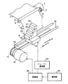
図1には、このようなインクジェット記録装置の記録部分の一般的な構成を示す。このものは、記録媒体として帯状の記録紙にインクジェット方式で画像を記録するものである。
【0006】
図中の2は、帯状の記録紙1の送り用のステップモータであって、このステップモータ2の回転は駆動ベルト3およびプーリ4を介して搬送ローラ5に伝達される。そして、この搬送ローラ5とピンチローラ6とで挟圧された記録紙1は、第1および第2のガイドローラ7,8に案内され、その長手方向すなわち副走査方向Yに所定のタイミングで送り出される。
【0007】
また、図中の10は、キャリッジを駆動する主走査モータであって、この主走査モータ10の出力軸に取付けられたプーリ11には無端状のタイミングベルト12が掛け渡され、このタイミングベルト12にはキャリッジ13が固定されている。そして、このキャリッジ13は、主走査方向Xと平行に設けられた一対のガイド14に案内され、この主走査方向Xに往方向Rおよび復方向Lに往復移動するように構成されている。
【0008】
また、上記のキャリッジ13には、カラー画像を記録するため、4色の各色毎の4個のマルチヘッド15,16,17,18が設けられている。図中の15は黒のインクを吐出するマルチヘッド、16はシアンインクを吐出するマルチヘッド、17はマジェンタインクを吐出するマルチヘッド、18はイエローインクを吐出するマルチヘッドである。上記の各マルチヘッド15,16,17,18には、インクドロップレットを吐出する複数の吐出口が配列されている。
【0009】
ところで、このマルチヘッドの製造工程の際の製造誤差等により、上記の複数の吐出口から吐出されるインクドロップレットの大きさや方向にばらつきが発生する。そして、このようなばらつきにより、印字画像に濃度のむらが発生し、画像の品質を低下させる不具合がある。
【0010】
次に、上記のような濃度のむらが発生する過程と、このような濃度のむらを防止する手段について説明する。図2は、このマルチヘッドたとえばマルチヘッド15と、インクドロップレットの記録媒体上の着弾ドットのパターン、および濃度分布を示す。図2は、このマルチヘッド15の各吐出口20から吐出されるインクドロップレット21の大きさおよび方向が均一な場合である。このような場合には、これらインクドロップレット21の記録紙上の着弾ドット22の大きさおよび配列が均一となり、図2の右側に示すように、画像の濃度分布が均一となる。
【0011】
また、図3にはこのマルチヘッド15の各吐出口20から吐出されるインクドロップレット21の大きさおよび方向が不均一な場合を示す。このような場合には、図3の中央部に示すように、これらインクドロップレット21の記録紙上の着弾ドット22の大きさおよび配列が不均一となり、図3の右側に示すように、画像の濃度分布が不均一となる。
【0012】
この図3に示すように、着弾ドット22大きさや配列が不均一となると、主走査方向に対して、周期的にエリアファクター100%を満たせない白紙の部分が存在したり、また逆に不必要にドットが重なり、また白い筋が発生する。このような不具合は、目視では通常濃度むらとして感知され、解像度の低下、コントラストの低下等、画像の品質の低下を招く。
【0013】
次に図4を参照して、上記のような濃度のむらを防止する手段について説明する。この手段は、1回の走査で全てのドットを埋めずに、互いに補完する2つのマスクパターンを用い、これを2回の走査すなわち2パスで全てのドットを埋めて画像を完成させるものである。
【0014】
図4には、これらの各走査すなわちパスと、吐出されるインクドロップレット21の関係を示す。マルチヘッド15は図3に示されているものと同一のものである。このマルチヘッド15には、8個の吐出口20が形成され、かつ記録紙1は副走査方向にこのマルチヘッド15の半分だけ、すなわち吐出口4個分だけ走査されるものである。なお、実際の装置では、記録紙1が副走査方向に移動されるものであるが、この図4では、理解を容易にするために、マルチヘッド15を各走査ごとにこの記録紙1に対して相対的にずらして描いてある。
【0015】
まず、図5の(a)に示すように、第1回目すなわち1パスの走査でこの図4および図5に描かれた記録すべき画像領域の上半分をマルチヘッド15の下半分の4個の吐出口20から吐出されるインクドロップレットにより、ドット22を記録する。この場合のドットのマスクパターンは、全部のドットの1/2に相当する数のドット22を一つおきの千鳥状に配列したパターンである。
【0016】
次に、図5の(b)に示すように、この記録紙1をマルチヘッド15の全長の1/2だけ副走査方向に移動させる。なお、前述のように、この図ではマルチヘッド15が記録紙1に対して相対的に移動したように描かれている。そして、このマルチヘッド15が2パス目の走査を行い、全部の吐出口20からのインクドロップレットにより、画像領域全体にドット22を形成する。この場合のドット22のマスクパターンは、上記の千鳥状のマスクパターンを補完するような逆の千鳥状のパターンである。これにより、この画像領域の上半分の画像が完成する。
【0017】
次に、図5の(c)に示すように、再び記録紙1をマルチヘッド15の全長の1/2だけ副走査方向に移動させ、次いでマルチヘッド15の3パス目の走査を行い、上半分の4個の吐出口20からのインクドロップレットにより、画像領域の下半分にドットを形成する。この場合のマスクパターンは、前述の千鳥状のパターンである。これにより、この画像領域全体の画像が完成する。
【0018】
なお、上記の図4および図5では、所定の1単位の画像領域のみ描かれているので、この画像領域の上半分、下半分を別々のパスにより記録するように説明されているが、実際のものでは、この画像領域は上下に連続しているので、1パス目の走査では、マルチヘッド15の上半分の4個の吐出口20からのインクドロップレットにより上に隣接する画像領域の下半分に千鳥状のパターンでドットを形成し、また3パス目の走査では、マルチヘッド15の下半分の4個の吐出口20からのインクドロップレットにより下に隣接する画像領域の上半分に千鳥状のパターンでドットを形成するものである。したがって、実際には、千鳥状、逆千鳥状の2つのマスクパターンで2パスで画像を完成する。
【0019】
このようにして形成されたドットパターンは、図4の中央部に示すように、ドット22の大きさや間隔の不均一が分散され、濃度のむらを解消する。なお、上記のものでは、2パスで画像を完成させているが、このように複数パスで画像を完成させる方法、すなわちマルチパス記録法では、パス数が多くなる程濃度がより均一化する。たとえば、全ドット数の1/4の互いに補完する4個のマスクパターンで4パスで画像を完成させるものでは、濃度がより均一化する。
【0020】
なお、このようにパス数が多くなると、単位画像領域の画像を完成させるに必要な時間が長くなり、印字速度が遅くなる不具合がある。このような不具合を防止するには、マルチヘッドの往動時にのみ印字走査をおこなわせるだけでなく、復動時にも印字走査をおこなう往復印字走査と云う記録方法もある。このような方法によれば、キャリッジが例えば図1の往方向Rに移動するときだけでなく、復方向Lに移動するときにも印字走査が行われ、記録時間を半分にすることができる。
【0021】
ところで、上記のようなマルチパス記録では、インクドロップレットの大きさや方向のばらつきによる濃度の不均一は防止できるが、その他の要因、たとえば往復印字走査の場合に、復動印字の際のインクドロップレットの吐出タイミングの遅れや、マルチヘッドの取付け角度のずれ等に起因して、濃度低下や規則的に濃度が相違する部分が帯状に発生する等の不具合が発生することが判明した。
【0022】
このような不具合は、上記のマルチパス記録の場合の規則性に基づくものである。すなわち、たとえば4パスで往復印字走査を行う場合には、マルチヘッドの複数の吐出口が4群に分けられ、各群では全記録画素のうち互いに1/4ずつの互いに相違する4個のマスクパターンを用いて、往動または復動走査で各単位画像領域にインクドロップレットを記録媒体に着弾させる。
【0023】
このため、このような方法では、4個の単位画像領域が形成され、各単位画像領域では、どの群の吐出口から吐出されたインクドロップレットが単位画像領域のどの位置に着弾してドットを形成するか、およびこのドットが往動走査で形成されたのか、または復動走査で形成されたのかが、各単位領域ごとに相違するが、この着弾ドットのパターンは規則的であり、4個の画像領域単位で反復する。
【0024】
もちろん、各インクドロップレットが所定の位置に正確に着弾すれば問題はないが、前記のようにインクドロップレットの吐出タイミングのずれ、マルチヘッドの取付け角度のずれ等が発生すると、各ドットの位置ずれが発生する。前述の各インクドロップレットの大きさや吐出角度のずれは、ランダムであるので、このようなマルチパス記録法により濃度むらを解消できるが、上記のようなインクドロップレットの吐出タイミングのずれ、マルチヘッドの取付け角度のずれ等は規則的であるので、この規則性と上記のマルチパス記録の規則性とが重畳し、これらに起因するドットのずれは規則的に現れ、濃度の低下を招き、また濃度の相違する縞が現れる不具合が生じ、このような不具合はバンディングと称されている。
【0025】
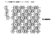
以下、この濃度低下やバンディング発生の原理について図7ないし図12を参照して説明する。なお、実際のドットは、図2に示すように、これらドットが正規に着弾した場合において隣接するドットの一部が互いに重なり、記録媒体上にドットで覆われていない無地の部分が形成されないように設定されている。しかし、以降の図では、ドットの位置およびずれの関係を明確にするために、各ドットが正規の配列パターンの場合には、隣接するドットが互いに重ならないような大きさに各ドットを図示してある。
【0026】
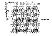
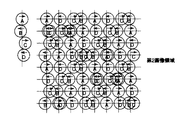
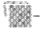
まず、図7および図12を参照して各走査におけるマスクパターンと、当該マスクパターンよって記録されるドットとの関係について説明する。なお、これ以降、第1回目の走査を「第1スキャン」、第2回目の走査を「第2スキャン」、第3回目の走査を「第3スキャン」、第4回目の走査を「第4スキャン」と呼称することとする。また、この図7では、一つのマルチヘッド例えばマルチヘッド15について説明してあるが、他のマルチヘッド16,17,18についても同様である。また、実際の装置では、記録紙が副走査方向に移動するものであるが、この図7ではマルチヘッド15が記録紙に対して相対的に移動したように描かれており、かつ各スキャンごとのマルチヘッド15の位置を描いてある。
【0027】
まず、上記のマルチヘッド15は、インクドロップレットの吐出口20が16個配列されており、これらは4個ずつ、A,B,C,Dの4群に分けられている。また、上記の記録紙は、副走査方向にこのマルチヘッド15の長さの1/4ずつ、すなわち各群の4個の吐出口分ずつ移動され、この移動ごとにマルチヘッド15が往動および復動スキャンを行い、図12に示されるそれぞれ異なる4個のマスクパターンでドットを形成する。ここでマスクパターンの黒丸で示され画素が記録画素、白丸で示されるのが非記録画素である。
【0028】
このような作動では、記録紙上に第1画像領域から第4画像領域の4個の単位画像領域が形成される。そして、各画像領域では、往動の第1スキャンで第1スキャン用のマスクパターンを用いてD群の吐出口20からのインクドロップレットでドットDが形成され、また復動の第2スキャンで第2スキャン用のマスクパターンを用いてC群の吐出口20からのインクドロップレットでドットCが形成され、また往動の第3スキャンで第3スキャン用のマスクパターンを用いてB群の吐出口20からのインクドロップレットでドットBが形成され、また復動の第4スキャンで第4スキャン用のマスクパターンを用いてA群の吐出口20からのインクドロップレットでドットAが形成され、以下、このような作動を繰り返して画像を完成させてゆくものである。
【0029】
次に、このような走査により画像を形成する際に、インクドロップレットの吐出タイミングがずれた場合に生じる記録媒体上でのドットの配列パターンへの影響を説明する。なお、ドット内の右向きの矢印は往動時に、左向きの矢印は復動時に着弾されたことを示している。また、図8ないし図11については、図中上から順に第1ないし第4画像領域を示している。この各画像領域は、説明と理解を容易にするために、間隔を空けて図示している。
【0030】
図8には、上記のずれが全く無い正規の場合のドットパターンが示されている。この場合には、ドットA、ドットB、ドットC、ドットD、は、正確に格子状に配列され、それらの間隔は均一である。
【0031】
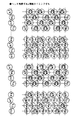
次に、たとえば復動すなわち復路において、インクドロップレットの吐出タイミングに遅れが発生した場合のドットの配列を図9に示す。この図9では、この遅れが2/10ドットピッチ(360dpiの場合には0.014mm)ずれた場合を示しているが、各ドットの大きさは実際とは相違し、説明のために模式的に示してある。なお、図9の左端には、A,B,C,Dの各ドットのずれ量を示してあり、復路のドット、すなわち図中左向きの矢印が付されたドットのみ正規の位置(図中上下方向に延在する線分)より左側にずれている。
【0032】
この図9から明らかなように、主走査方向のドットライン上において、復動時のドットB,Dが隣接する往動時のドットA,Cと一部重なるか、もしくはドットの間隔が広がる。隣接ドットの間隔が広がると、インクドロップレットが着弾されていない無地の部分が増えることになり、このため各画像領域ではその濃度が低下し、コントラストの低下、解像度の低下等、画像の品質の低下を招く。なお、この場合には、各画像領域におけるドットの配列パターンはほぼ同じであるので、単に全画像領域の濃度が平均的に低下したように見え、全画像領域全体としての品質の劣化はさほど目立たない。
【0033】
次に、マルチヘッド15が主走査方向と副走査方向とを含む平面内で正規の取付け角度からマルチヘッド15の上部を中心に傾いた場合のドットの配列パターンを図10に示す。なお、図10の左端には、A,B,C,Dの各ドットのずれ量を示してあり、ドットAを中心(正規の位置)に、ドットBが1/10ドットピッチ、ドットCが2/10ドットピッチ、ドットDが3/10ドットピッチだけ正規の位置から右方にずれている。
【0034】
この図10から明らかなように、主走査方向のドットライン上において、ドットAとドットDの間隔が広くなっており、インクドロップレットの着弾されていない無地の部分が増えている。このため各画像領域ではその濃度が低下し、コントラストの低下、解像度の低下等、画像の品質の低下を招く。なお、この場合にも、各画像領域におけるドットの配列パターンはほぼ同じであるので、単に全画像領域の濃度が平均的に低下したように見え、全画像領域全体としての品質の劣化はさほど目立たない。
【0035】
このように、単にインクドロップレットの吐出タイミングがずれただけ、あるいは、マルチヘッド15が正規の取付角度からずれただけでは、記録される画像の品質の劣化はそれほど目立たない。しかしながら、この両者が同時に発生した場合には、記録される画像の品質の劣化が顕著に目立ってしまう。
【0036】
図11には、復動すなわち復路においてインクドロップレットの吐出タイミングに遅れが発生し、かつマルチヘッド15が正規の取付角度から傾けられて取付けられた場合のドットの配列パターンが示されている。
【0037】
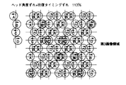
なお、図11の左端には、タイミングの遅れと角度の傾きが複合された場合のA,B,C,Dの各ドットのずれ量が示されている。なお、吐出タイミングのずれ(遅れ量)、さらにマルチヘッド15の取付角度のずれ(方向、量)は、それぞれ前述した場合と同じであり、両者のずれ量が重畳されている。このため各ドットの正規の位置からのずれ量は第1、第3画像領域では、ドットAが左方に2/10ドットピッチ、ドットBが右方に2/10ドットピッチ、ドットCが0、ドットDが右方に3/10ドットピッチずれることになり、また第2、第4画像領域ではドットAが0、ドットBが左方に1/10ドットピッチ、ドットCが右方に2/10ドットピッチ、ドットDが左方に1/10ドットピッチだけずれる。
【0038】
この図から明らかなように、第1画像領域と第3画像領域とはほぼ同じドット配列パターンであり、第2画像領域と第4画像領域とはほぼ同じドット配列パターンとなっているが、第1、第3画像領域と第2、第4画像領域とは異なるドット配列パターンとなっている。そして、主走査方向におけるドットライン上での隣接ドットの最大間隔が第1,3画像領域の方が第2,4画像領域に対して大きいため、画像濃度が低く見える。つまり、記録媒体上の第1ないし第4画像領域が順に形成されると、濃度レベルが低、高、低、高、低・・・と繰り返されることになり、画像領域ごとに濃度むらが交互に現れるいわゆるバンディングが現れ、画像領域全体の画像の品質の劣化が顕著に目立ってしまう。
【0039】
上記のように、インクドロップレットの吐出タイミングのずれ、またはマルチヘッドの取付け角度のずれのみの場合には、解像度、コントラストの低下等、画像品位の低下を招き、好ましくはない。また、インクドロップレットの吐出タイミングのずれ、およびマルチヘッドの取付け角度のずれが重なった場合には、各単位画像領域ごとの縞状の濃度むらすなわちバンディングが発生し、画像品位の大幅な低下を招く。
【0040】
もちろん、このような不具合を防止するには、インクドロップレットの吐出タイミングや、マルチヘッドの取付け角度等を較正すればよい。しかし、上記の吐出タイミングや取付け角度の較正は面倒な作業であるとともに、この記録装置の使用期間中にこれら吐出タイミングや取付け角度が経時的に変化し、これらを常に正確に調整、較正することは困難であった。
【0041】
【発明が解決しようとする課題】
本発明は以上の事情に基づいてなされたもので、マルチパス記録法において発生する濃度低下やバンディング等による画像品質の低下を効果的に低減し、かつインクドロップレットの吐出タイミングや、マルチヘッドの取付け角度等の調整や較正を特に必要とせず、簡単に画像品質の劣化を低減できる記録装置を提供するものである。
【0042】
【課題を解決するための手段】
請求項1に記載の発明は、非記録画素と記録画素とが配列され、各記録走査毎に互いに補完するマスクパターンを設定し、インクを吐出する複数の吐出部を有する記録ヘッドを記録媒体の同一記録領域に対して、前記マスクパターンに基づいて複数回走査することにより画像を完成するインクジェット記録装置において、記録媒体上の単位面積当たりに付着されるインク量を、正規のインク量に対する比率であるインクデューティー比を100%以上とするように、記録媒体上の同一画素について記録画素が重複する重複記録画素を前記マスクパターンに設定したことを特徴とするものである。
【0043】
前述したように、インクの吐出のタイミングのずれ、または記録ヘッドの取付角度のずれ、またはその両方が重なった場合には、これによる画像への悪影響は濃度の低下あるいは濃度むらとなって現れる。よって、このような不具合が発生した場合には、インクデューティー比を100%以上とし、濃度を高くすることにより上記の濃度低下あるいは濃度むらによる画像品質の低下を防止できる。
【0044】
このような発明によれば、インクの吐出タイミングの調整、記録ヘッドの取付角度の調整などの面倒な調整作業をおこなうことなく、単にインクデューティー比を大きくして濃度を高くするだけで、これらのずれによる画像品質の劣化を低減することができ、調整が極めて簡単である。
【0045】
特に、バンディングすなわち画像領域の間で全体の濃度に差が発生し、記録される記録画素即ち着弾ドットが所定の正規の配列位置からずれている場合には有効で、他のマスクパターン、すなわち他のスキャンで記録されるマスクパターンの同一画素に重複して着弾ドットを重ねれば、この画素における複数の着弾ドットは必ず互いにずれて記録され、最終的なドットの径が実質的に大きくなる。このため、この領域においては、ドットで覆われる部分の面積が広くなり、エリアファクターが増大するのでこの領域の濃度が高くなり、濃度の低下や規則的に現れる濃度の相違する縞を解消し、バンディングを防止できる。
【0046】
また、単にドットを重複して記録するだけの簡単な操作であるため、インクドロップレットの吐出タイミングや、マルチヘッドの取付け角度等の調整、較正を必要とせず、マルチヘッドの制御回路を変更するだけで簡単に実施でき、また装置の構造も複雑になることはない。
【0047】
また、上記の重複記録画素の数は調整可能であるので、記録紙の紙質、インクの種類、その他の条件に対応して重複記録画素の数、すなわちこの画像領域の濃度を適切に設定することができ、画像の品質の低下、バンディングをより効果的に防止できる。
【0048】
なお、本明細書における「インクデューティー比」とは、記録媒体の単位面積当たりに付着されるインクの正規の量を100%とした場合に、実際に記録媒体上の単位面積当たりに付着されるインクの量の比率を示すものとする。
【0049】
なお、このインクデューティー比を100%以上とする手段は、後述するように、記録媒体のピクセル上にドットを二度打ちする場合、または記録ヘッドに印加する電圧や駆動デューティー比を調整して吐出されるインクドロップレットの量を変更する場合、その他の場合を含むものとする。
【0050】
また、上記の重複記録画素の数は調整可能であるので、記録紙の紙質、インクの種類、その他の条件に対応して重複記録画素の数、すなわちこの画像領域の濃度を適切に設定することができ、画像の品質の低下、バンディングをより効果的に防止できる。
【0051】
また、請求項8に記載の発明は、記録媒体上の単位面積当たりに付着されるインク量を、正規のインク量に対する比率であるインクデューティー比を100%以上とするように、各記録走査毎に前記記録ヘッドに印加する電圧を変化させることを特徴とするものである。
【0052】
従って、この電圧を変化させることにより、吐出されるインクドロップレットの径が大きくなり、着弾ドットの径も大きくなる。よって、この領域の濃度を高くし、濃度の低下や領域ごとの濃度の差を解消し、バンディングを防止できる。
【0053】
また、このような操作は、単に記録ヘッドに印加する電圧を変化させるだけの簡単な操作であり、インクドロップレットの吐出タイミングや、マルチヘッドの取付け角度等の調整、較正を必要とせず、マルチヘッドの駆動回路を変更するだけで簡単に実施でき、また装置の構造も複雑になることはない。
【0054】
また、上記の電圧すなわちインクドロップレットの径は調整可能であるので、記録紙の紙質、インクの種類、その他の条件に対応してドットの径、すなわちこの画像領域の濃度を適切に設定することができ、バンディングをより効果的に防止できる。
【0055】
また、請求項13に記載の発明は、記録媒体上の単位面積当たりに付着されるインク量を、正規のインク量に対する比率であるインクデューティー比を100%以上とするように、各記録走査毎に前記記録ヘッドの各吐出部に設けられるヒータの駆動デューティーを変化させることを特徴とするものである。
【0056】
従って、バブルジェット方式の記録ヘッドでは、このヒータの駆動デューティを変化させることにより、吐出されるインクドロップレットの径が大きくなり、着弾ドットの径も大きくなる。よって、この領域の濃度を高くし、濃度の低下や領域ごとの濃度の差を解消し、バンディングを防止できる。
【0057】
また、このような操作は、単に記録ヘッドのヒータの駆動デューティを変化させるだけの簡単な操作であり、インクドロップレットの吐出タイミングや、マルチヘッドの取付け角度等の調整、較正を必要とせず、マルチヘッドの駆動回路を変更するだけで簡単に実施でき、また装置の構造も複雑になることはない。
【0058】
また、上記の駆動デューティすなわちインクドロップレットの径は調整可能であるので、記録紙の紙質、インクの種類、その他の条件に対応してドットの径、すなわちこの領域の濃度を適切に設定することができ、バンディングをより効果的に防止できる。
【0059】
また、請求項18に記載の発明は、前記記録ヘッドにより記録されたテストパターンを読み取り、その読取結果から前記記録ヘッドからのインクの吐出タイミングのずれまたは前記記録ヘッドの取付角度のずれの少なくともいずれかを検出し、その検出結果に基づいて最適なインクデューティー比を選択すると共に、選択されたインクデューティー比に対応するマスクパターンを選択することを特徴とするものである。
【0060】
前述のように、インクの吐出タイミングのずれ、記録ヘッドの取付角度のずれによる影響は、濃度低下、濃度むらとなって現れ、これにより画像の品質が劣化する。このような影響は、画像の目視により判定しなければならず、その判定に熟練を必要とするが、この発明によれば、テストパターンのドットの分布から、インクの吐出タイミングや記録ヘッドの取付角度のずれを検出でき、これらから着弾ドットの配列パターンを予め判別し、濃度低下や濃度むらの態様を予め判定して適切な濃度の補正が自動的にできる。
【0061】
【発明の実施の形態】
以下、図を参照して本発明の実施形態を説明する。図6、7および図13ないし図46を参照して本発明の第1の実施形態を説明する。この実施形態は、インクジェット記録装置であって、互いに記録画素配列が異なる4個のマスクパターンを用いて4パス記録を行うマルチパス記録法で、かつキャリッジの往路および復路の両方で印字をおこなう往復印字走査を行う記録装置に本発明を適用したものである。
【0062】
図6には、この記録装置の要部を概略的に示したもので、この装置の記録部分の構成は前述の図1に示したものと略同様である。すなわち、図中の2は、帯状の記録紙1の送り用のステップモータであって、このステップモータ2の回転は駆動ベルト3およびプーリ4を介して搬送ローラ5に伝達される。そして、この搬送ローラ5とピンチローラ6とで挟圧された記録紙1は、第1および第2のガイドローラ7,8に案内され、その長手方向すなわち副走査方向Yに所定のタイミングで送り出される。
【0063】
また、図中の10は、キャリッジを駆動する主走査モータであって、この主走査モータ10の出力軸に取付けられたプーリ11には無端状のタイミングベルト12が掛け渡され、このタイミングベルト12にはキャリッジ13が固定されている。そして、このキャリッジ13は、主走査方向Xと平行に設けられた一対のガイド14に案内され、この主走査方向Xに往方向Rおよび復方向Lに往復移動するように構成されている。
【0064】
また、上記のキャリッジ13には、カラー画像を記録するため、4色の各色毎の4個のマルチヘッド15,16,17,18が設けられている。図中の15は黒のインクを吐出するマルチヘッド、16はシアンインクを吐出するマルチヘッド、17はマジェンタインクを吐出するマルチヘッド、18はイエローインクを吐出するマルチヘッドである。
【0065】
上記のステップモータ2、主走査モータ10およびキャリッジ13のマルチヘッド15,16,17,18等は、制御部30によって制御されるように構成されている。また、この制御部30には、操作部31からの信号が入力されるように構成され、記録紙の紙質、印字モードやその他の各種設定値が設定可能となっている。
【0066】
また、上記のマルチヘッド15,16,17,18からのインクドロップレットの吐出のパターンすなわちマスクパターンは、パターン設定器32により制御されている。また、このパターン設定器32では、正規のパターンでインクドロップレットの吐出を制御する他に、所定のパターンで重複したドットを形成するように構成されている。なお、このパターン設定器32の作用は後述する。
【0067】
次に、上記のようなバンディングを解消する手段について説明する。本発明の基本的な手段は、ドットの径を大きくし、記録媒体上の単位面積当たりに付着するインクの量、すなわちインクデューティー比を大きくし、これにより濃度を高めて濃度むらを解消するものである。
【0068】
この実施形態の場合には、記録媒体上の記録されるべき全ピクセルに対してインクドロップレットを着弾させるとともに、記録されるべき全ピクセルよりも少ない数のピクセルに対してさらにインクドロップレットを着弾させる、いわゆる二度打ちを行うように各スキャンのマスクパターンを設定している。すなわち、ドットが2つ着弾されたピクセル上のドット径は、実質的に他の(1つしか着弾されていない)ピクセル上のドット径より大きくなり、これによって濃度低下の原因である記録媒体上の無地部分を覆うようにするものである。なお、記録媒体のピクセル上に着弾された2つのドットから形成された径の大きなドットを複合ドットと称し、さらに、各マスクパターンの正規の記録画素に対応して着弾するドットを通常ドットと称し、各マスクパターンで他のマスクパターンの通常ドットに重ねて二度打ちされるドットを重複ドットと称する。また、重複ドットに相当するマスクパターン上の記録画素を重複記録画素と称する。
【0069】
図12の従来の8×8画素のマスクパターンは、記録媒体上の記録されるべき全ピクセルに対してインクドロップレットがそれぞれ1つずつ着弾される、いわゆるインクデューティー比100%の場合のマスクパターンを示している。(黒丸が記録画素、白丸が非記録画素)これに対して本実施形態のマスクパターンは、図13に示すように、図12のマスクパターンに比べて、インクデューティー比が106%となるように、各スキャンにおけるマスクパターンにそれぞれ重複記録画素を1個設けている。図中でハッチングを付した丸が重複記録画素である。これらのマスクパターンを用いて4パス記録を行うと、重複記録画素に基づいて重複インクドロップレットが吐出され、記録媒体上に通常ドットと重ねて重複ドットが二度打ちされ、複合ドットを形成することになる。
【0070】
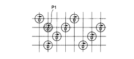
なお、上記のようなマスクパターンを用いて記録媒体上にドットを着弾させる過程を図47ないし図52を参照して説明する。まず最初に、第1スキャン用のマスクパターンを用い往動の第1スキャンで図47に示すようなドットパターンで通常ドットDを着弾させる。この場合に、この画像領域の2行2列の位置P1のピクセルに重複記録画素に対応して重複ドットDが着弾する。
【0071】
次に、第2スキャン用のマスクパターンを用い、復動の第2スキャンで図48に示すように通常ドットCを着弾させる。さらに、第3スキャン用のマスクパターンを用い往動の第3スキャンで図49に示すようなドットパターンで通常ドットBを着弾させる。この場合に、2行2列の位置P1のピクセルに上記の重複ドットDが着弾しているので、この上に通常ドットBが着弾して2個のドットが重なった複合ドットが形成される。なお、上記のように、重複ドットDと通常ドットBとの着弾順序は、どちらが先でもよく、この場合のように重複ドットDが着弾した後に通常ドットBが着弾する場合もある。
【0072】
さらに、第4スキャン用のマスクパターンを用い、復動の第4スキャンで図50に示すように通常ドットAを着弾させる。この場合に、この画像領域の4行7列の位置P2に重複記録画素に対応して重複ドットAが着弾する。この重複ドットAは、先に着弾している通常ドットCと重なり、複合ドットを形成する。
【0073】
図51には、通常ドットBと重複ドットDがずれて着弾した場合に形成される複合ドット22Dの一例を示す。このように、ドットがずれた場合には、略長円方の大きな複合ドット22Dが形成される。また、図52には、通常ドットBと重複ドットDとが同じ位置に着弾した場合に形成される複合ドット22Dの例を示す。この場合には、この複合ドット22Dは略円形になり、図51の複合ドット22Dより面積はやや小さくなるが、通常の1個のドットの場合より大径となる。
【0074】
なお、この重複ドットすなわち複合ドットの位置は、バンディングを解消するに適した位置に均一に分散するように設定する。前述した図9ないし図11に示すように、インクドロップレットの吐出タイミングのずれ、またはマルチヘッドの取付け角度のずれ、またはこれらが両方重なった場合のドットのパターンのずれ、すなわちバンディングの態様は、予め解析しておくことができる。よって、このような予備的な解析に基づいて、重複ドットの位置を適宜設定しておくことができる。
【0075】
この図13に示したようなマスクパターンで重複ドットを設定した場合の効果を示す。図19ないし図22には、上記のようなマルチヘッドの取付け角度のずれと往復時のインクドロップレットの吐出タイミングの遅れとが重なった場合に、重複ドットを打たなかった場合の第1ないし第4の画像領域の全ドットの着弾パターンを示す。そして、図23ないし図26には、同様な場合に図13に示すマスクパターンで重複ドットを打った場合の全ドットの着弾パターンを示す。これらの図を比較すると、各画像領域ごとの濃度の差が縮小し、バンディングが減少していることが示されている。
【0076】
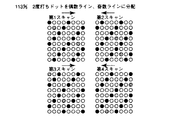
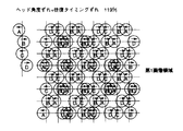
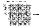
また、図14には、インクデューティー比が113%となるように、各スキャンごとに2個の重複ドットを設定した場合のマスクパターンを示す。そして、この場合のドットの着弾パターンを図27ないし図30に示す。この場合にも、図19ないし図22と比較して、各画像領域ごとの濃度の差が縮小し、バンディングが減少していることが示されている。
【0077】
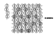
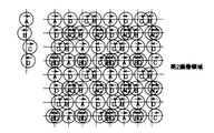
また、図15には、インクデューティー比が119%となるように、各スキャンごとに3個の重複ドットを設定した場合のマスクパターンを示す。そして、この場合のドットの着弾パターンを図31ないし図34に示す。この場合にも、図19ないし図22と比較して、各画像領域ごとの濃度の差が縮小し、バンディングが減少していることが示されている。
【0078】
また、図16には、インクデューティー比が125%となるように、各スキャンごとに4個の重複ドットを設定した場合のマスクパターンを示す。そして、この場合のドットの着弾パターンを図35ないし図38に示す。この場合にも、図19ないし図22と比較して、各画像領域ごとの濃度の差が縮小し、バンディングが減少していることが示されている。
【0079】
なお、上記の各例では、重複ドットは、同一方向の主走査方向、すなわち往動スキャン、または復動スキャンの場合にのみ打つようにしたが、往動スキャンおよび復動スキャンの両方で重複ドットを打つように設定してもよい。
【0080】
また、図17には、インクデューティー比が113%となるように、各スキャンごとに2個の重複ドットを設定した場合のパターンを示す。そして、この場合のドットの着弾パターンを図39ないし図42に示す。この場合にも、図19ないし図22と比較して、各画像領域ごとの濃度の差が縮小し、バンディングが減少していることが示されている。
【0081】
一般に、ドットの位置ずれはヘッドの走査方向にずれる場合が多い。したがって、上記の例では、このような走査方向のずれが生じた場合、通常ドットに対する重複ドットの位置ずれ量が大きくなり、図51に示すように、より大きな面積の複合ドットが形成される。よって、濃度の低下、バンディングをより効果的に低減させ、より高い品質の画像が得られる。
【0082】
また、図18には、インクデューティー比が113%となるように、各スキャンごとに2個の重複ドットを設定し、かつこれら重複ドットを偶数ライン、奇数ラインに分配した場合のマスクパターンを示す。そして、この場合のドットの着弾パターンを図43ないし図46に示す。この場合にも、図19ないし図22と比較して、各画像領域ごとの濃度の差が縮小し、バンディングが減少していることが示されている。
【0083】
このように、重複ドットを偶数ライン、奇数ライン上に配置することにより、全ライン上に重複ドットすなわち複合ドットが配置される。よって、記録媒体たとえば記録紙の送り量にむらが発生した場合でも、画像の品質の低下を少なくすることができる。
【0084】
なお、上述の通常ドット、着弾ドットおよび複合ドットの大きさ等は、各種の条件、たとえば記録媒体である記録紙の紙質、インクの粘性等により変化する。
したがって、上記のような重複ドットを設定するためのマスクパターンは、これらの条件および発生するバンディングの予備的な解析結果等から、複数のマスクパターンを設定しておき、これらは前述したパターン設定器32に記憶されている。
【0085】
なお、本発明者らの実験の結果、この重複ドットの配置パターンは、インクデューティー比が106%〜125%の範囲がバンディング解消に有効である。また、前述のようにこの重複ドットにより形成される複合ドットの径は大きくなるので、これら重複ドットをあまり近接させて配置すると、画像のざらつきが大きくなり、画像品位を低下させるので、これら重複ドットは互いに離れるように均一に配置することが好ましい。
【0086】
そして、この装置の操作者は、上記の各種の条件に基づいて入力指示部すなわち操作部31を操作し、最適の重複ドットパターンに対応したマスクパターンを選択する。たとえば、記録紙のインク吸収性が大きい場合には、ドットの大きさが大きくなるので、その分だけインクデューティー比が小さくなるようなマスクパターンを選択するようにすればよい。
【0087】
なお、この実施形態では、上記の重複ドットのパターンは装置の操作者が設定するように構成されているが、たとえば制御部30または外部のコンピュータ等に、記録媒体である記録紙の紙質、インクの種類等の条件に対応して最適の重複ドットのパターンを選択するようなプログラムを設定しておき、各種の条件を入力するだけで自動的に最適の重複ドットのパターンを選択するようにしてもよい。
【0088】
なお、本発明は上記の第1の実施形態には限定されない。たとえば、図53には、本発明の第2の実施形態を示す。このものは、記録ヘッドすなわちマルチヘッド15,16,17,18に印加する電圧を設定する電圧設定器42を備えている。この電圧設定器42は、この記録ヘッドに用いられている電気機械変換体、たとえばピエゾ素子に印加させる電圧を所定の割合で高くし、より径の大きなインクドロップレットを吐出させ、着弾ドットを大きくして隣接するドットの間の最大間隙を減少させるようにしたものである。
【0089】
この実施形態では、印加電圧を高くするのは、4回のスキャンのうち第4のスキャンによりインクドロップレットを吐出する場合についてである。この電圧設定器42には、少なくとも2つの値のヘッド駆動電圧V1およびV2が設定されている。代の電圧V1は、所定の印字モードに適した電圧である。第2の電圧V2は、より大きなインクドロップレットを吐出させるためのヘッド駆動電圧である。
【0090】
この大きなインクドロップレットにより着弾ドットの径を大きくすることにより、各画像領域で生じる濃度のむらによるバンディングを解消する。この径の大きなインクドロップレットを吐出するのは、第4スキャンに限らず、その他の一つまたは2つのスキャンの際でもよい。
【0091】
また、印加電圧はV1とV2の2個の値に限らず、複数の印加電圧値を印加するようにしてもよい。この場合に、各スキャンごとに印加電圧を変えてもよい。
このようにすることにより、インクの種類や記録紙の種類等に応じて、最適の径のインクドロップレットを吐出させることがてきる。
【0092】
この実施形態のものは、インクドロップレットのインク量を大きくすることによりドット径を大きくするもので、その作用効果は前記の第1の実施形態と同様である。なお、この実施形態のものは、上記の点以外は前記の第1の実施形態と同様の構成であり、図53中で第1の実施形態と対応する部分には同じ符号を付し、その説明は省略する。
【0093】
また、図54には、本発明の第3の実施形態を示す。このものは、記録ヘッドすなわちマルチヘッド15,16,17,18がバブルジェット方式のインクドロップレット吐出機構を採用している場合のものである。この実施形態のものは、この記録ヘッドの電気熱変換体であるヒータの駆動デューティを変化させるデューティ設定器52を備えている。このものは、ヒータの駆動デューティを大きくし、より大きな径のインクドロップレットを吐出させるもので、これ以外は前記の第2の実施形態と同様の構成である。なお、図54中で上記の第1または第2の実施形態に対応する部分は同じ符号を付してその説明は省略する。
【0094】
また、図55には本発明の第4の実施形態を示す。このものは、キャリッジ13にドットスキャナ61を設け、印字に先立って行われる各マスクパターンのテストパターンの印字のドットの配列パターンをこのドットスキャナ61により検出するように構成されている。そして、このドットの配列パターンは、テストパターン判定部62で処理され、前述したようなインクドロップレットの吐出タイミングの遅れや、マルチヘッドの取付角度のずれ等が判定される。
【0095】
そして、これにより前述のような印字の際のドットの配列パターンおよびこれに基づく濃度の低下や濃度むら等が予め判定され、これらに基づいて最適のマスクパターンのインクデューティー比の選択等の濃度調整が自動的に行われる。
【0096】
前述のように、インクドロップレットの吐出タイミングの遅れや、マルチヘッドの取付角度のずれ等による画像への影響は、濃度低下、濃度むら等となって現れ、これにより画像の品質が劣化する。このような画像品質の劣化は、目視により判定されなければならないが、正確な劣化判定には熟練を必要とする。しかし、この実施形態のものは、テストパターンから吐出タイミングのずれや記録ヘッドの取付角度のずれを自動的に判定して最適の濃度調整ができ、非熟練者であっても、容易に操作でき、かつ正確な濃度調整が可能であり、より高品質の画像が得られる。
【0097】
なお、図55中で上記の第1の実施形態に対応する部分は同じ符号を付してその説明は省略する。また、この実施形態では、濃度調整は前記の第1の実施形態と同様に重複ドットによるインクデューティー比の調整によりおこなっているが、前述の第2または第3の実施形態のように、ヘッドへの印加電圧の調整、駆動デューティーの調整などにより行っても良い。
【0098】
さらに、本発明は、上記のような実施形態にも限定されず。たとえば濃度調整手段は、全インクドロップレットの径すなわちインク量の調整により行ってもよく、要は記録媒体上の単位面積当たりに付着されるインクの量を正規の場合より多くして濃度調整を行えば良い。
【0099】
また、本発明は上記の実施形態にも限定されず、たとえばインクジェット方式の記録装置に限らず、レーザプリンタ等の他のデジタル形の記録方式のものにも適用が可能である。
【0100】
なお、上述したように、本明細書には以下のような発明が開示され、かつ含まれている。
【0101】
(1) 非記録画素と記録画素とが配列され、各記録走査毎に互いに補完するマスクパターンを複数設定し、インクを吐出する複数の吐出部を有する記録ヘッドを記録媒体の同一記録領域に対して複数回走査することにより画像を完成するインクジェット記録装置において、
上記の記録ヘッドからのインクの吐出タイミングのずれまたは上記の記録ヘッドの取付角度のずれの少なくともいずれかに起因する画像の濃度むらを、記録媒体上の単位面積当たりに付着されるインクの量を、正規のインクの量に対する比率であるインクデューテイ比を100%以上とすることにより低減する濃度補正手段を備えたことを特徴とするインクジェット記録装置。
【0102】
(2) 非記録画素と記録画素とが配列され、各記録走査毎に互いに補完するマスクパターンを複数設定し、インクを吐出する複数の吐出部を有する記録ヘッドを記録媒体の同一記録領域に対して複数回走査することにより画像を完成するインクジェット記録装置において、
上記の複数のマスクパターンのうちの異なるマスクパターン間で同一画素について記録画素が重複する重複記録画素を設定し、かつこの重複記録画素の数を調整可能としたことを特徴とするインクジェット記録装置。
【0103】
(3) 前記の(2)において、前記の重複記録画素は、同一方向の走査時に用いられる複数のマスクパターンに設定されていることを特徴とするインクジェット記録装置。
【0104】
(4) 前記の(2)において、前記の重複記録画素は、異なる方向の走査時に用いられる複数のマスクパターンに設定されていることを特徴とするインクジェット記録装置。
【0105】
(5) 前記の(2)において、
キャリッジが主走査方向に往復移動している間にインクを吐出して画像記録を行う双方向記録モードと、
キャリッジが主走査方向に往動している間のみにインクを吐出して画像記録を行う片方向記録モードと、
を有し、
前記の双方向記録モードのマスクパターン群に設定される重複記録画素数を、前記の片方向記録モード時のマスクパターン群に設定される重複記録画素数よりも増加させることを特徴とするインクジェット記録装置。
【0106】
(6) 前記の(2)において、前記の重複記録画素数の設定値ごとに複数種のマスクパターン群を有し、これら複数種のマスクパターン群から1つを選択させるインクジェット記録装置。
【0107】
(7) 前記(6)において、操作者がマスクパターンを指示するための入力指示部を有することを特徴とするインクジェット記録装置。
【0108】
(8) 前記の(7)において、操作者が前記の記録媒体の種類を入力する入力部と、前記の入力部の入力値に応じてマスクパターンを選択する選択部とを有するインクジェット記録装置。
【0109】
(9) 非記録画素と記録画素とが配列され、各記録走査毎に互いに補完するマスクパターンを複数設定し、インクを吐出する複数の吐出部を有する記録ヘッドを記録媒体の同一記録領域に対して複数回走査することにより画像を完成するインクジェット記録装置において、
上記の各マスクパターン毎の各記録走査毎に、上記の記録ヘッドに印加する電圧を変化させることを特徴とするインクジェット記録装置。
【0110】
(10) 前記の(9)において、
キャリッジが主走査方向に往復移動している間にインクを吐出して画像記録を行う双方向記録モードと、
キャリッジが主走査方向に往動している間のみにインクを吐出して画像記録を行う片方向記録モードと、
を有し、
前記の双方向記録モード時の印加電圧を、前記の片方向記録モード時の印加電圧よりも大きくすることを特徴とするインクジェット記録装置。
【0111】
(11) 前記の(9)または(10)において、各記録走査ごとに前記記録ヘッドに印加する電圧値を複数用意しておき、前記の複数の電圧値から所望の電圧値を選択することを特徴とするインクジェット記録装置。
【0112】
(12) 前記(11)において、操作者が印加電圧を指示するための入力指示部を有することを特徴とするインクジェット記録装置。
【0113】
(13) 前記の(11)において、操作者が前記の記録媒体の種類を入力する入力部と、前記の入力部の入力値に応じて印加電圧を選択する選択部とを有するインクジェット記録装置。
【0114】
(14) 非記録画素と記録画素とが配列され、各記録走査毎に互いに補完するマスクパターンを複数設定し、インクを吐出する複数の吐出部を有する記録ヘッドを記録媒体の同一記録領域に対して複数回走査することにより画像を完成するインクジェット記録装置において、
上記の各マスクパターン毎の各記録走査毎に、上記の記録ヘッドの各吐出部に対応するヒータの駆動デューティを変化させることを特徴とするインクジェット記録装置。
【0115】
(15) 前記の(14)において、
キャリッジが主走査方向に往復移動している間にインクを吐出して画像記録を行う双方向記録モードと、
キャリッジが主走査方向に往動している間のみにインクを吐出して画像記録を行う片方向記録モードと、
を有し、
前記の双方向記録モード時の駆動デューティを、前記の片方向記録モード時の駆動デューティよりも大きくすることを特徴とするインクジェット記録装置。
【0116】
(16) 前記の(14)または(15)において、前記の駆動デューティを複数用意しておき、前記の複数の駆動デューティーから所望の駆動デューティを選択することを特徴とするインクジェット記録装置。
【0117】
(17) 前記(16)において、操作者が駆動デューティを指示するための入力指示部を有することを特徴とするインクジェット記録装置。
【0118】
(18) 前記の(16)において、操作者が前記の記録媒体の種類を入力する入力部と、前記の入力部の入力値に応じて駆動デューティを選択する選択部とを有するインクジェット記録装置。
【0119】
(19) 非記録画素と記録画素とが配列され、各記録走査毎に互いに補完するマスクパターンを複数設定し、インクを吐出する複数の吐出部を有する記録ヘッドを記録媒体の同一記録領域に対して複数回走査することにより画像を完成するインクジェット記録装置において、
上記の記録ヘッドからのインクの吐出タイミングのずれまたは上記の記録ヘッドの取付角度のずれの少なくともいずれかに起因する画像の濃度むらを、記録媒体上の単位面積当たりに付着されるインクの量を、正規のインクの量に対する比率であるインクデューテイ比を100%以上とすることにより低減する濃度補正手段を備え、
この濃度補正手段は、前記の記録ヘッドにより形成されたテストパターンのドットを検出し、このテストパターンのドットの分布から前記の記録ヘッドからのインクの吐出タイミングのずれまたは上記の記録ヘッドの取付角度のずれの少なくともいずれかを検出し、これに対応して前記のインクデューテイ比を設定するものであることを特徴とするインクジェット記録装置。
【0120】
【発明の効果】
上述の如く本発明によれば、マルチパス記録かつ往復印字で記録する場合におけるインクドロップレットの着弾ずれや記録ヘッドの取付け角度のずれにより生じる濃度低下や濃度むらを減少させて画像品質の劣化を減少させることができ、かつインクドロップレットの吐出タイミングや記録ヘッドの取付け角度のずれ等を調整、較正する必要もなく、容易に実施できる等、その効果は大である。
【図面の簡単な説明】
【図1】従来のインクジェット記録装置の要部の概略図。
【図2】従来のインクジェット記録装置のドットパターンの説明図。
【図3】従来のインクジェット記録装置のドットパターンの説明図。
【図4】従来のインクジェット記録装置のドットパターンの説明図。
【図5】従来のインクジェット記録装置のマスクパターンの説明図。
【図6】本発明の第1の実施形態のインクジェット記録装置の要部の概略図。
【図7】本発明の第1の実施形態のインクジェット記録装置のドットパターンの説明図。
【図8】第1の実施形態のドットパターンの説明図。
【図9】第1の実施形態のドットパターンの説明図。
【図10】第1の実施形態のドットパターンの説明図。
【図11】第1の実施形態のドットパターンの説明図。
【図12】第1の実施形態のマスクパターンの説明図。
【図13】第1の実施形態のマスクパターンの説明図。
【図14】第1の実施形態のマスクパターンの説明図。
【図15】第1の実施形態のマスクパターンの説明図。
【図16】第1の実施形態のマスクパターンの説明図。
【図17】第1の実施形態のマスクパターンの説明図。
【図18】第1の実施形態のマスクパターンの説明図。
【図19】第1の実施形態のドットパターンの説明図。
【図20】第1の実施形態のドットパターンの説明図。
【図21】第1の実施形態のドットパターンの説明図。
【図22】第1の実施形態のドットパターンの説明図。
【図23】第1の実施形態のドットパターンの説明図。
【図24】第1の実施形態のドットパターンの説明図。
【図25】第1の実施形態のドットパターンの説明図。
【図26】第1の実施形態のドットパターンの説明図。
【図27】第1の実施形態のドットパターンの説明図。
【図28】第1の実施形態のドットパターンの説明図。
【図29】第1の実施形態のドットパターンの説明図。
【図30】第1の実施形態のドットパターンの説明図。
【図31】第1の実施形態のドットパターンの説明図。
【図32】第1の実施形態のドットパターンの説明図。
【図33】第1の実施形態のドットパターンの説明図。
【図34】第1の実施形態のドットパターンの説明図。
【図35】第1の実施形態のドットパターンの説明図。
【図36】第1の実施形態のドットパターンの説明図。
【図37】第1の実施形態のドットパターンの説明図。
【図38】第1の実施形態のドットパターンの説明図。
【図39】第1の実施形態のドットパターンの説明図。
【図40】第1の実施形態のドットパターンの説明図。
【図41】第1の実施形態のドットパターンの説明図。
【図42】第1の実施形態のドットパターンの説明図。
【図43】第1の実施形態のドットパターンの説明図。
【図44】第1の実施形態のドットパターンの説明図。
【図45】第1の実施形態のドットパターンの説明図。
【図46】第1の実施形態のドットパターンの説明図。
【図47】ドット着弾の過程を示すドットパターンの説明図。
【図48】ドット着弾の過程を示すドットパターンの説明図。
【図49】ドット着弾の過程を示すドットパターンの説明図。
【図50】ドット着弾の過程を示すドットパターンの説明図。
【図51】複合ドットの説明図。
【図52】複合ドットの説明図。
【図53】本発明の第2の実施形態のインクジェット記録装置の要部の概略図。
【図54】本発明の第3の実施形態のインクジェット記録装置の要部の概略図。
【図55】本発明の第4の実施形態のインクジェット記録装置の要部の概略図。
【符号の説明】
1 記録紙
13 キャリッジ
15,16,17,18 マルチヘッド
20 吐出口
21 インクドロップレット
22 ドット
32 パターン設定器
42 電圧設定器
52 デューティ設定器[0001]
BACKGROUND OF THE INVENTION
The present invention relates to a recording apparatus, for example, an ink jet recording apparatus, and particularly to a recording apparatus that makes an image quality deterioration inconspicuous due to positional deviation of landing dots during reciprocal printing.
[0002]
More specifically, the present invention relates to a recording apparatus that can easily perform the correction of the positional deviation of the landing dots without requiring mechanical adjustment.
[0003]
[Prior art]
With the spread of information processing devices such as copying machines, word processors, computers, and communication devices, devices that record information as images, for example, recording devices that perform digital image recording using an ink jet recording head, are rapidly becoming popular. ing.
[0004]
In such a recording apparatus, in order to improve the recording speed, a recording head in which a plurality of recording elements are integrated, that is, a multi-head is used. For example, in an ink jet recording apparatus, a plurality of ink discharge ports and flow paths are integrated in an array. In general, a recording apparatus includes a plurality of multi-heads and a plurality of multi-heads for each color corresponding to a color image.
[0005]
FIG. 1 shows a general configuration of a recording portion of such an ink jet recording apparatus. This is to record an image on a belt-like recording paper as a recording medium by an ink jet method.
[0006]
[0007]
[0008]
The
[0009]
By the way, variations in the size and direction of the ink droplets ejected from the plurality of ejection ports are caused by a manufacturing error in the manufacturing process of the multihead. Due to such variations, there is a problem that density unevenness occurs in the printed image and the quality of the image is deteriorated.
[0010]
Next, a process in which the density unevenness as described above occurs and means for preventing such density unevenness will be described. FIG. 2 shows this multi-head, for example, the multi-head 15, the pattern of landing dots on the recording medium of ink droplets, and the density distribution. FIG. 2 shows a case where the size and direction of the
[0011]
FIG. 3 shows a case where the size and direction of the
[0012]
As shown in FIG. 3, when the size and arrangement of the
[0013]
Next, referring to FIG. 4, a means for preventing the density unevenness as described above will be described. This means uses two mask patterns that complement each other without filling all dots in one scan, and fills all dots in two scans, that is, two passes to complete the image. .
[0014]
FIG. 4 shows the relationship between each of these scans or passes and the
[0015]
First, as shown in FIG. 5A, the upper half of the image area to be recorded drawn in FIG. 4 and FIG. The
[0016]
Next, as shown in FIG. 5B, the
[0017]
Next, as shown in FIG. 5 (c), the
[0018]
In FIGS. 4 and 5, since only a predetermined unit image area is drawn, it is described that the upper half and the lower half of the image area are recorded by separate passes. In this case, since the image area is continuous in the vertical direction, in the first pass scanning, the ink droplets from the four
[0019]
In the dot pattern formed in this way, as shown in the center portion of FIG. 4, the unevenness of the size and interval of the
[0020]
Note that when the number of passes increases in this way, the time required to complete the image of the unit image area becomes long, and there is a problem that the printing speed becomes slow. In order to prevent such a problem, there is a recording method called reciprocating print scanning in which print scanning is performed not only when the multi-head moves forward but also during backward movement. According to such a method, for example, not only when the carriage moves in the forward direction R of FIG. 1, but also when the carriage moves in the backward direction L, the printing scan is performed, and the recording time can be halved.
[0021]
By the way, in the multi-pass printing as described above, density unevenness due to variations in the size and direction of ink droplets can be prevented. It has been found that problems such as a drop in density and a regular difference in density occur in a band shape due to a delay in the discharge timing of the let or a shift in the mounting angle of the multihead.
[0022]
Such a defect is based on the regularity in the case of the multipass recording described above. That is, for example, when performing reciprocal print scanning in four passes, a plurality of discharge ports of the multi-head are divided into four groups, and each group has four masks which are different from each other by 1/4 of all the recording pixels. By using the pattern, ink droplets are landed on the recording medium in each unit image area by forward or backward scanning.
[0023]
For this reason, in such a method, four unit image areas are formed, and in each unit image area, the ink droplets ejected from which group of ejection ports land on which position in the unit image area to form dots. Whether each dot is formed and whether this dot is formed by forward scanning or backward scanning is different for each unit area, the pattern of the landing dots is regular, and four Repeat for each image area.
[0024]
Of course, there is no problem if each ink droplet lands exactly at a predetermined position. However, if the ink droplet ejection timing is misaligned or the multihead mounting angle is misaligned as described above, the position of each dot Deviation occurs. Since the deviations in the sizes and ejection angles of the ink droplets described above are random, density unevenness can be eliminated by such a multi-pass printing method. Since the regularity of the mounting angle of the lens is regular, this regularity and the regularity of the multi-pass recording described above are superimposed, and the resulting dot misalignment appears regularly, leading to a decrease in density, and There arises a problem that stripes having different densities appear, and such a problem is called banding.
[0025]
Hereinafter, the principle of density reduction and banding will be described with reference to FIGS. In addition, as shown in FIG. 2, when these dots land normally, some of the adjacent dots overlap each other so that the solid dots that are not covered with the dots are not formed on the recording medium. Is set to However, in the following figures, in order to clarify the relationship between dot positions and displacement, each dot is illustrated in such a size that adjacent dots do not overlap each other when each dot is a regular array pattern. It is.
[0026]
First, the relationship between the mask pattern in each scan and the dots recorded by the mask pattern will be described with reference to FIGS. After this, the first scan is the “first scan”, the second scan is the “second scan”, the third scan is the “third scan”, and the fourth scan is the “fourth scan”. It will be referred to as “scan”. Further, although FIG. 7 illustrates one multi-head, for example, the multi-head 15, the same applies to the other multi-heads 16, 17, and 18. In an actual apparatus, the recording paper moves in the sub-scanning direction. In FIG. 7, however, the
[0027]
First, the multi-head 15 has 16 ink
[0028]
In such an operation, four unit image areas from the first image area to the fourth image area are formed on the recording paper. Then, in each image area, dots D are formed by ink droplets from the
[0029]
Next, the influence on the dot arrangement pattern on the recording medium that occurs when the ejection timing of the ink droplets is shifted when an image is formed by such scanning will be described. Note that the right-pointing arrow within the dot indicates that it has landed during forward movement, and the left-pointing arrow indicates that it has landed during backward movement. 8 to 11, the first to fourth image regions are shown in order from the top in the drawing. Each image region is illustrated with an interval in between for easy explanation and understanding.
[0030]
FIG. 8 shows a normal dot pattern in which there is no such deviation. In this case, the dot A, the dot B, the dot C, and the dot D are accurately arranged in a lattice pattern, and the distance between them is uniform.
[0031]
Next, FIG. 9 shows an arrangement of dots when a delay occurs in the ejection timing of ink droplets, for example, in the backward movement, that is, in the backward path. FIG. 9 shows a case where this delay is shifted by 2/10 dot pitch (0.014 mm in the case of 360 dpi), but the size of each dot is different from the actual size, and is schematically shown for explanation. It is shown in The left end of FIG. 9 shows the deviation amount of each of the dots A, B, C, and D, and only the dot on the return path, that is, the dot with the arrow pointing to the left in the figure is the normal position (up and down in the figure). The line segment extending in the direction is shifted to the left.
[0032]
As is apparent from FIG. 9, on the dot line in the main scanning direction, the dots B and D at the time of backward movement partially overlap the adjacent dots A and C at the time of forward movement, or the interval between the dots is widened. As the interval between adjacent dots increases, the solid area where the ink droplets are not landed increases, and this reduces the density in each image area, reducing the contrast, reducing the resolution, and so on. Incurs a decline. In this case, since the dot arrangement pattern in each image area is almost the same, the density of the entire image area seems to have decreased on average, and the deterioration of the quality of the entire image area as a whole is so conspicuous. Absent.
[0033]
Next, FIG. 10 shows an arrangement pattern of dots when the multi-head 15 is tilted around the upper part of the multi-head 15 from a normal mounting angle in a plane including the main scanning direction and the sub-scanning direction. The left end of FIG. 10 shows the deviation amounts of the dots A, B, C, and D. The dot B is 1/10 dot pitch and the dot C is centered on the dot A (regular position). The 2/10 dot pitch and the dot D are shifted to the right from the normal position by 3/10 dot pitch.
[0034]
As is apparent from FIG. 10, the interval between the dots A and D is wide on the dot line in the main scanning direction, and the solid portion where the ink droplets are not landed increases. For this reason, the density of each image region is reduced, which leads to a reduction in image quality such as a reduction in contrast and a reduction in resolution. Also in this case, since the dot arrangement pattern in each image area is almost the same, the density of the entire image area seems to have decreased on average, and the deterioration of the quality of the entire image area is so conspicuous. Absent.
[0035]
As described above, the deterioration of the quality of the recorded image is not so conspicuous if the ejection timing of the ink droplets is simply shifted or if the
[0036]
FIG. 11 shows an arrangement pattern of dots when the ink droplet discharge timing is delayed in the backward movement, that is, in the return path, and the
[0037]
The left end of FIG. 11 shows the deviation amounts of the dots A, B, C, and D when the timing delay and the angle inclination are combined. In addition, the deviation (delay amount) of the ejection timing and the deviation (direction and amount) of the mounting angle of the multi-head 15 are the same as those described above, and the deviation amounts of both are superimposed. For this reason, in the first and third image areas, the deviation amount of each dot from the normal position is 2/10 dot pitch on the left side, 2/10 dot pitch on the right side, and 0 on the dot C side in the first and third image regions. , Dot D is shifted by 3/10 dot pitch to the right, and in the second and fourth image areas, dot A is 0, dot B is 1/10 dot pitch to the left, and dot C is 2 to the right. / 10 dot pitch, dot D is shifted to the left by 1/10 dot pitch.
[0038]
As is clear from this figure, the first image region and the third image region have substantially the same dot arrangement pattern, and the second image region and the fourth image region have substantially the same dot arrangement pattern. The first and third image areas and the second and fourth image areas have different dot arrangement patterns. Since the maximum distance between adjacent dots on the dot line in the main scanning direction is larger in the first and third image areas than in the second and fourth image areas, the image density looks low. That is, when the first to fourth image areas on the recording medium are sequentially formed, the density level is repeated as low, high, low, high, low,..., And density unevenness alternates for each image area. So-called banding appears, and the deterioration of the image quality of the entire image area becomes noticeable.
[0039]
As described above, if the ink droplet ejection timing is misaligned or the multi-head mounting angle is misaligned, the image quality is degraded such as a decrease in resolution and contrast, which is not preferable. In addition, when the ink droplet ejection timing shift and the multi-head mounting angle shift overlap, striped density unevenness, that is, banding, occurs in each unit image area, resulting in a significant reduction in image quality. Invite.
[0040]
Of course, in order to prevent such a problem, it is only necessary to calibrate the discharge timing of the ink droplets, the mounting angle of the multihead, and the like. However, the calibration of the discharge timing and the mounting angle described above is a troublesome work, and the discharge timing and the mounting angle change with the lapse of time during the use period of the recording apparatus, and these are always adjusted and calibrated accurately. Was difficult.
[0041]
[Problems to be solved by the invention]
The present invention has been made based on the above circumstances, and can effectively reduce the deterioration of image quality due to density reduction and banding that occur in the multipass printing method, and can also reduce the discharge timing of the ink droplets and the multihead. It is an object of the present invention to provide a recording apparatus that can easily reduce deterioration in image quality without requiring any adjustment or calibration of the mounting angle.
[0042]
[Means for Solving the Problems]
According to the first aspect of the present invention, a non-recording pixel and a recording pixel are arranged, a mask pattern that complements each other is set for each recording scan, and a recording head having a plurality of ejection units that eject ink is provided on the recording medium. In an ink jet recording apparatus that completes an image by scanning the same recording area a plurality of times based on the mask pattern, the amount of ink deposited per unit area on the recording medium is expressed as a ratio to the regular ink amount. The mask pattern is used to set overlapping recording pixels in which the recording pixels overlap for the same pixel on the recording medium so that a certain ink duty ratio is 100% or more.
[0043]
As described above, when the ink ejection timing shift, the print head mounting angle shift, or both overlap, an adverse effect on the image appears as a decrease in density or uneven density. Therefore, when such a problem occurs, the ink duty ratio is set to 100% or more, and the density is increased to prevent the above-described reduction in density or deterioration in image quality due to density unevenness.
[0044]
According to such an invention, it is possible to simply increase the ink duty ratio to increase the density without performing troublesome adjustment work such as adjustment of the ink ejection timing and adjustment of the mounting angle of the recording head. Degradation of image quality due to deviation can be reduced, and adjustment is extremely simple.
[0045]
This is particularly effective when there is a difference in the overall density between banding or image areas, and the recorded pixels to be recorded, i.e., landing dots, deviate from a predetermined regular arrangement position. If landing dots are overlapped on the same pixel of the mask pattern recorded in this scan, the plurality of landing dots in this pixel are always recorded shifted from each other, and the final dot diameter is substantially increased. For this reason, in this region, the area of the portion covered with dots is widened and the area factor is increased, so that the concentration of this region is increased, eliminating the decrease in density and the fringes with different density appearing regularly, Banding can be prevented.
[0046]
Also, since it is a simple operation that simply records dots in duplicate, adjustment of the ink droplet discharge timing, multihead mounting angle, etc., and calibration are not required, and the multihead control circuit is changed. This is easy to implement, and the structure of the device is not complicated.
[0047]
Also, since the number of overlapping recording pixels can be adjusted, the number of overlapping recording pixels, that is, the density of this image area, should be set appropriately in accordance with the paper quality of the recording paper, the type of ink, and other conditions. Image quality can be effectively prevented from being degraded and banding.
[0048]
Note that the “ink duty ratio” in this specification means that the ink is actually attached per unit area on the recording medium when the normal amount of ink attached per unit area of the recording medium is 100%. The ratio of the amount of ink shall be shown.
[0049]
The means for setting the ink duty ratio to 100% or more is ejected when a dot is shot twice on a pixel of the recording medium or the voltage applied to the recording head or the driving duty ratio is adjusted, as will be described later. When the amount of ink droplets to be changed is changed, other cases are included.
[0050]
Also, since the number of overlapping recording pixels can be adjusted, the number of overlapping recording pixels, that is, the density of this image area, should be set appropriately in accordance with the paper quality of the recording paper, the type of ink, and other conditions. Image quality can be effectively prevented from being degraded and banding.
[0051]
Also,According to the eighth aspect of the present invention, the ink amount per unit area on the recording medium is set to 100% or more for each recording scan so that the ink duty ratio, which is a ratio to the regular ink amount, is 100% or more. The voltage applied to the recording head is changed.
[0052]
Therefore, by changing this voltage, the diameter of the ejected ink droplet increases and the diameter of the landing dot also increases. Therefore, it is possible to increase the density of this area, eliminate the decrease in density and the density difference between areas, and prevent banding.
[0053]
In addition, such an operation is a simple operation that simply changes the voltage applied to the recording head, and does not require adjustment or calibration of the ink droplet ejection timing, the multihead mounting angle, etc. This can be done simply by changing the head drive circuit, and the structure of the apparatus is not complicated.
[0054]
In addition, since the voltage, that is, the diameter of the ink droplet can be adjusted, the dot diameter, that is, the density of this image area, should be set appropriately in accordance with the recording paper quality, ink type, and other conditions. And banding can be prevented more effectively.
[0055]
Also,According to a thirteenth aspect of the present invention, the ink amount deposited per unit area on the recording medium is set to 100% or more for each recording scan so that the ink duty ratio, which is a ratio to the regular ink amount, is 100% or more. The present invention is characterized in that the drive duty of a heater provided in each ejection portion of the recording head is changed.
[0056]
Therefore, in the bubble jet type recording head, by changing the driving duty of the heater, the diameter of the ejected ink droplet is increased and the diameter of the landing dot is also increased. Therefore, it is possible to increase the density of this area, eliminate the decrease in density and the density difference between areas, and prevent banding.
[0057]
In addition, such an operation is a simple operation that simply changes the drive duty of the heater of the recording head, and does not require adjustment or calibration of the ink droplet ejection timing, the mounting angle of the multihead, etc. This can be implemented simply by changing the multi-head drive circuit, and the structure of the apparatus is not complicated.
[0058]
In addition, since the drive duty, that is, the diameter of the ink droplet can be adjusted, the dot diameter, that is, the density of this region, should be set appropriately in accordance with the paper quality of the recording paper, the type of ink, and other conditions. And banding can be prevented more effectively.
[0059]
Also,According to an eighteenth aspect of the present invention, a test pattern recorded by the recording head is read, and at least one of a deviation in ink ejection timing from the recording head and a deviation in the mounting angle of the recording head is read from the read result. In addition, an optimum ink duty ratio is selected based on the detection result, and a mask pattern corresponding to the selected ink duty ratio is selected.
[0060]
As described above, the influence of the deviation of the ejection timing of the ink and the deviation of the mounting angle of the recording head appears as density reduction and density unevenness, thereby degrading the image quality. Such an influence must be determined by visual inspection of the image, and skill is required for the determination. According to the present invention, from the distribution of the dots in the test pattern, the ink ejection timing and the mounting of the recording head An angle shift can be detected, and an arrangement pattern of landing dots can be determined in advance from these, and a mode of density reduction or density unevenness can be determined in advance to automatically correct an appropriate density.
[0061]
DETAILED DESCRIPTION OF THE INVENTION
Hereinafter, embodiments of the present invention will be described with reference to the drawings. A first embodiment of the present invention will be described with reference to FIGS. 6 and 7 and FIGS. This embodiment is an inkjet recording apparatus, which is a multi-pass recording method in which four-pass recording is performed using four mask patterns having different recording pixel arrangements, and reciprocation in which printing is performed both in the forward path and the return path of the carriage. The present invention is applied to a recording apparatus that performs print scanning.
[0062]
FIG. 6 schematically shows the main part of this recording apparatus, and the configuration of the recording part of this apparatus is substantially the same as that shown in FIG. That is, 2 in the figure is a step motor for feeding the belt-
[0063]
[0064]
The
[0065]
The
[0066]
The pattern of ink droplets discharged from the multi-heads 15, 16, 17, and 18, that is, the mask pattern is controlled by the
[0067]
Next, a means for eliminating the above banding will be described. The basic means of the present invention is to increase the dot diameter and increase the amount of ink deposited per unit area on the recording medium, that is, the ink duty ratio, thereby increasing the density and eliminating the density unevenness. It is.
[0068]
In this embodiment, ink droplets are landed on all the pixels to be recorded on the recording medium, and ink droplets are landed on a smaller number of pixels than all the pixels to be recorded. The mask pattern for each scan is set to perform so-called double hitting. That is, the dot diameter on the pixel on which two dots have landed is substantially larger than the dot diameter on the other (only one landed) pixel, thereby causing the density reduction on the recording medium. It is intended to cover the plain part. A dot having a large diameter formed from two dots landed on a pixel of the recording medium is referred to as a composite dot, and a dot landed corresponding to a regular recording pixel of each mask pattern is referred to as a normal dot. In each mask pattern, a dot that is hit twice by overlapping with a normal dot of another mask pattern is referred to as an overlapping dot. A recording pixel on the mask pattern corresponding to the overlapping dot is referred to as an overlapping recording pixel.
[0069]
The conventional 8 × 8 pixel mask pattern of FIG. 12 is a so-called one in which ink droplets are landed on all the pixels to be recorded on the recording medium.Ink duty ratioA mask pattern in the case of 100% is shown. (The black circle is a recording pixel, and the white circle is a non-recording pixel.) On the other hand, as shown in FIG.Ink duty ratioIs set to 106%, one overlapping recording pixel is provided in each mask pattern in each scan. In the figure, hatched circles are overlapping recording pixels. When four-pass printing is performed using these mask patterns, overlapping ink droplets are ejected based on the overlapping recording pixels, and the overlapping dots are printed twice on the recording medium so as to overlap with the normal dots, thereby forming a composite dot. It will be.
[0070]
The process of landing dots on the recording medium using the mask pattern as described above will be described with reference to FIGS. First, normal dots D are landed with a dot pattern as shown in FIG. 47 in the forward first scan using the mask pattern for the first scan. In this case, the overlapping dot D lands on the pixel at position P1 in 2 rows and 2 columns of the image area corresponding to the overlapping recording pixel.
[0071]
Next, using the mask pattern for the second scan, the normal dot C is landed as shown in FIG. Furthermore, the normal dot B is landed with a dot pattern as shown in FIG. 49 in the forward third scan using the mask pattern for the third scan. In this case, since the overlap dot D has landed on the pixel at the position P1 in 2 rows and 2 columns, the normal dot B has landed on this and a composite dot in which the two dots overlapped is formed. As described above, the landing order of the overlapping dot D and the normal dot B may be either first, and the normal dot B may land after the overlapping dot D has landed as in this case.
[0072]
Further, using the mask pattern for the fourth scan, the normal dot A is landed as shown in FIG. In this case, the overlapping dot A is landed corresponding to the overlapping recording pixel at the position P2 of 4 rows and 7 columns in this image area. This overlapping dot A overlaps with the previously landed normal dot C to form a composite dot.
[0073]
FIG. 51 shows an example of the
[0074]
Note that the positions of the overlapping dots, that is, the composite dots are set so as to be uniformly distributed at positions suitable for eliminating banding. As shown in FIG. 9 to FIG. 11 described above, the deviation of the ejection timing of the ink droplets, the deviation of the mounting angle of the multi-head, or the deviation of the dot pattern when they both overlap, that is, the mode of banding, It can be analyzed in advance. Therefore, the position of the overlapping dot can be set as appropriate based on such preliminary analysis.
[0075]
The effect when overlapping dots are set with the mask pattern as shown in FIG. FIGS. 19 to 22 show the first to non-overlapping dots when the above-described misalignment of the multi-head mounting angle overlaps the delay of the ink droplet ejection timing during reciprocation. The landing pattern of all dots in the fourth image area is shown. FIG. 23 to FIG. 26 show landing patterns of all dots when overlapping dots are hit with the mask pattern shown in FIG. 13 in the same case. Comparing these figures, it is shown that the density difference for each image area is reduced and banding is reduced.
[0076]
In addition, FIG.Ink duty ratioShows a mask pattern when two overlapping dots are set for each scan so that is 113%. The dot landing patterns in this case are shown in FIGS. Also in this case, as compared with FIGS. 19 to 22, it is shown that the density difference for each image region is reduced and the banding is reduced.
[0077]
In addition, FIG.Ink duty ratioThe mask pattern in the case where three overlapping dots are set for each scan so that becomes 119% is shown. The dot landing patterns in this case are shown in FIGS. Also in this case, as compared with FIGS. 19 to 22, it is shown that the density difference for each image region is reduced and the banding is reduced.
[0078]
In addition, FIG.Ink duty ratioShows a mask pattern when four overlapping dots are set for each scan so that is 125%. The dot landing patterns in this case are shown in FIGS. Also in this case, as compared with FIGS. 19 to 22, it is shown that the density difference for each image region is reduced and the banding is reduced.
[0079]
In each of the above examples, overlapping dots are hit only in the same main scanning direction, that is, forward scanning or backward scanning. However, overlapping dots are used in both forward scanning and backward scanning. You may set to hit.
[0080]
In addition, FIG.Ink duty ratioShows a pattern when two overlapping dots are set for each scan so that is 113%. The dot landing patterns in this case are shown in FIGS. Also in this case, as compared with FIGS. 19 to 22, it is shown that the density difference for each image region is reduced and the banding is reduced.
[0081]
In general, the positional deviation of dots is often shifted in the scanning direction of the head. Therefore, in the above example, when such a shift in the scanning direction occurs, the positional shift amount of the overlapping dots with respect to the normal dots increases, and a composite dot having a larger area is formed as shown in FIG. Therefore, density reduction and banding can be more effectively reduced, and higher quality images can be obtained.
[0082]
Also, in FIG.Ink duty ratioShows a mask pattern when two overlapping dots are set for each scan so that the ratio is 113% and these overlapping dots are distributed to even lines and odd lines. The dot landing patterns in this case are shown in FIGS. Also in this case, as compared with FIGS. 19 to 22, it is shown that the density difference for each image region is reduced and the banding is reduced.
[0083]
In this way, by arranging overlapping dots on even lines and odd lines, overlapping dots, that is, composite dots are arranged on all lines. Therefore, even when the feeding amount of the recording medium, for example, the recording paper is uneven, the deterioration of the image quality can be reduced.
[0084]
Note that the sizes of the above-described normal dots, landing dots, and composite dots vary depending on various conditions, for example, the quality of recording paper as a recording medium, the viscosity of ink, and the like.
Therefore, a mask pattern for setting overlapping dots as described above is set with a plurality of mask patterns based on these conditions and preliminary analysis results of generated banding. 32.
[0085]
As a result of the experiments by the present inventors, the arrangement pattern of the overlapping dots isInk duty ratioThe range of 106% to 125% is effective for eliminating banding. In addition, since the diameter of the composite dots formed by the overlapping dots is increased as described above, if these overlapping dots are arranged too close, the roughness of the image increases and the image quality is lowered. Are preferably arranged so as to be separated from each other.
[0086]
Then, the operator of this apparatus operates the input instruction unit, that is, the
[0087]
In this embodiment, the above-described overlapping dot pattern is configured to be set by the operator of the apparatus. However, for example, the
[0088]
Note that the present invention is not limited to the first embodiment. For example, FIG. 53 shows a second embodiment of the present invention. This includes a
[0089]
In this embodiment, the applied voltage is increased when the ink droplets are ejected by the fourth scan among the four scans. In the
[0090]
By increasing the diameter of the landing dot with this large ink droplet, banding due to uneven density in each image area is eliminated. The ejection of ink droplets having a large diameter is not limited to the fourth scan, and may be performed during one or two other scans.
[0091]
Further, the applied voltage is not limited to two values of V1 and V2, and a plurality of applied voltage values may be applied. In this case, the applied voltage may be changed for each scan.
By doing so, ink droplets having an optimum diameter can be ejected according to the type of ink, the type of recording paper, and the like.
[0092]
In this embodiment, the dot diameter is increased by increasing the ink amount of the ink droplet, and the operation and effect thereof are the same as those of the first embodiment. In addition, the thing of this embodiment is the structure similar to the said 1st Embodiment except said point, and attaches | subjects the same code | symbol to the part corresponding to 1st Embodiment in FIG. Description is omitted.
[0093]
FIG. 54 shows a third embodiment of the present invention. This is the case where the recording head, that is, the multi-heads 15, 16, 17, 18 employs a bubble jet type ink droplet discharge mechanism. This embodiment includes a
[0094]
FIG. 55 shows a fourth embodiment of the present invention. In this apparatus, a
[0095]
As a result, the dot arrangement pattern at the time of printing as described above and density reduction or density unevenness based on the pattern are determined in advance, and based on these, the optimum mask pattern is determined.Ink duty ratioThe density adjustment such as selection is automatically performed.
[0096]
As described above, the influence on the image due to the delay of the ejection timing of the ink droplets, the deviation of the mounting angle of the multi-head, etc. appears as density reduction, density unevenness, etc., thereby degrading the image quality. Such image quality degradation must be determined visually, but skill is required for accurate degradation determination. However, according to this embodiment, it is possible to automatically determine the deviation of the ejection timing and the deviation of the mounting angle of the recording head from the test pattern and perform the optimum density adjustment, and even an unskilled person can easily operate it. In addition, accurate density adjustment is possible, and a higher quality image can be obtained.
[0097]
In FIG. 55, parts corresponding to those in the first embodiment are given the same reference numerals, and descriptions thereof are omitted. In this embodiment, the density adjustment is performed by overlapping dots as in the first embodiment.Ink duty ratioHowever, it may be performed by adjusting the voltage applied to the head, adjusting the drive duty, or the like, as in the second or third embodiment described above.
[0098]
Furthermore, the present invention is not limited to the embodiment as described above. For example, the density adjusting means may be performed by adjusting the diameter of all ink droplets, that is, the amount of ink. In short, the density adjustment is performed by increasing the amount of ink deposited per unit area on the recording medium as compared with a normal case. Just do it.
[0099]
The present invention is not limited to the above-described embodiments, and is applicable not only to an ink jet recording apparatus but also to other digital recording systems such as a laser printer.
[0100]
As described above, the present invention discloses and includes the following inventions.
[0101]
(1) A non-recording pixel and a recording pixel are arranged, a plurality of mask patterns that complement each other are set for each recording scan, and a recording head having a plurality of ejection units that eject ink is disposed on the same recording area of the recording medium. In an inkjet recording apparatus that completes an image by scanning multiple times,
The density unevenness of the image caused by at least one of the deviation of the ejection timing of the ink from the recording head or the deviation of the mounting angle of the recording head is calculated by the amount of ink attached per unit area on the recording medium. An ink jet recording apparatus comprising density correction means for reducing the ink duty ratio, which is a ratio with respect to the amount of regular ink, to 100% or more.
[0102]
(2) A non-recording pixel and a recording pixel are arranged, a plurality of mask patterns that complement each other are set for each recording scan, and a recording head having a plurality of ejecting portions that eject ink is disposed on the same recording area of the recording medium. In an inkjet recording apparatus that completes an image by scanning multiple times,
An ink jet recording apparatus characterized in that overlapping recording pixels in which recording pixels overlap between the same mask patterns among the plurality of mask patterns are set, and the number of the overlapping recording pixels can be adjusted.
[0103]
(3) The inkjet recording apparatus according to (2), wherein the overlapping recording pixels are set to a plurality of mask patterns used for scanning in the same direction.
[0104]
(4) The inkjet recording apparatus according to (2), wherein the overlapping recording pixels are set to a plurality of mask patterns used when scanning in different directions.
[0105]
(5) In the above (2),
A bidirectional recording mode in which image recording is performed by ejecting ink while the carriage reciprocates in the main scanning direction;
A unidirectional recording mode in which image recording is performed by ejecting ink only while the carriage is moving forward in the main scanning direction;
Have
Ink jet recording, characterized in that the number of overlapping recording pixels set in the mask pattern group in the bidirectional recording mode is increased more than the number of overlapping recording pixels set in the mask pattern group in the one-way recording mode. apparatus.
[0106]
(6) An ink jet recording apparatus according to (2), wherein a plurality of types of mask pattern groups are provided for each set value of the number of overlapping recording pixels, and one is selected from the plurality of types of mask pattern groups.
[0107]
(7) The inkjet recording apparatus according to (6), further including an input instruction unit for an operator to instruct a mask pattern.
[0108]
(8) An ink jet recording apparatus according to (7), wherein the operator has an input unit for inputting the type of the recording medium, and a selection unit for selecting a mask pattern according to an input value of the input unit.
[0109]
(9) A non-recording pixel and a recording pixel are arranged, a plurality of mask patterns that complement each other are set for each recording scan, and a recording head having a plurality of ejection units that eject ink is disposed on the same recording area of the recording medium. In an inkjet recording apparatus that completes an image by scanning multiple times,
An ink jet recording apparatus, wherein the voltage applied to the recording head is changed for each recording scan for each mask pattern.
[0110]
(10) In the above (9),
A bidirectional recording mode in which image recording is performed by ejecting ink while the carriage reciprocates in the main scanning direction;
A unidirectional recording mode in which image recording is performed by ejecting ink only while the carriage is moving forward in the main scanning direction;
Have
An ink jet recording apparatus, wherein an applied voltage in the bidirectional recording mode is larger than an applied voltage in the unidirectional recording mode.
[0111]
(11) In (9) or (10) above, preparing a plurality of voltage values to be applied to the recording head for each recording scan, and selecting a desired voltage value from the plurality of voltage values. An ink jet recording apparatus.
[0112]
(12) The inkjet recording apparatus according to (11), further including an input instruction unit for an operator to instruct an applied voltage.
[0113]
(13) An ink jet recording apparatus according to (11), further comprising: an input unit through which an operator inputs the type of the recording medium; and a selection unit that selects an applied voltage in accordance with an input value of the input unit.
[0114]
(14) A non-recording pixel and a recording pixel are arranged, a plurality of mask patterns that complement each other are set for each recording scan, and a recording head having a plurality of ejection portions that eject ink is disposed on the same recording area of the recording medium. In an inkjet recording apparatus that completes an image by scanning multiple times,
An ink jet recording apparatus, wherein a drive duty of a heater corresponding to each ejection portion of the recording head is changed for each recording scan for each mask pattern.
[0115]
(15) In the above (14),
A bidirectional recording mode in which image recording is performed by ejecting ink while the carriage reciprocates in the main scanning direction;
A unidirectional recording mode in which image recording is performed by ejecting ink only while the carriage is moving forward in the main scanning direction;
Have
An ink jet recording apparatus, wherein a driving duty in the bidirectional recording mode is larger than a driving duty in the unidirectional recording mode.
[0116]
(16) The inkjet recording apparatus according to (14) or (15), wherein a plurality of the drive duties are prepared, and a desired drive duty is selected from the plurality of drive duties.
[0117]
(17) The inkjet recording apparatus according to (16), further including an input instruction unit for an operator to instruct a driving duty.
[0118]
(18) The inkjet recording apparatus according to (16), wherein the operator includes an input unit that inputs a type of the recording medium, and a selection unit that selects a driving duty according to an input value of the input unit.
[0119]
(19) A non-recording pixel and a recording pixel are arranged, a plurality of mask patterns that complement each other are set for each recording scan, and a recording head having a plurality of ejection units that eject ink is disposed on the same recording area of the recording medium. In an inkjet recording apparatus that completes an image by scanning multiple times,
The density unevenness of the image due to at least one of the deviation of the ejection timing of the ink from the recording head or the deviation of the mounting angle of the recording head is calculated by the amount of ink attached per unit area on the recording medium. A density correction means for reducing the ink duty ratio, which is a ratio with respect to the amount of regular ink, by 100% or more,
This density correction means detects the dots of the test pattern formed by the recording head, and the deviation of the ink ejection timing from the recording head or the mounting angle of the recording head from the dot distribution of the test pattern An ink jet recording apparatus characterized in that at least one of the deviations is detected and the ink duty ratio is set correspondingly.
[0120]
【The invention's effect】
As described above, according to the present invention, image quality is deteriorated by reducing density drop and density unevenness caused by deviation of landing of ink droplets and deviation of the mounting angle of the recording head in multipass recording and reciprocal printing. The effect can be reduced, and it can be easily carried out without the need to adjust and calibrate the ink droplet ejection timing, the recording head mounting angle deviation, and the like.
[Brief description of the drawings]
FIG. 1 is a schematic view of a main part of a conventional ink jet recording apparatus.
FIG. 2 is an explanatory diagram of a dot pattern of a conventional ink jet recording apparatus.
FIG. 3 is an explanatory diagram of a dot pattern of a conventional ink jet recording apparatus.
FIG. 4 is an explanatory diagram of a dot pattern of a conventional ink jet recording apparatus.
FIG. 5 is an explanatory diagram of a mask pattern of a conventional inkjet recording apparatus.
FIG. 6 is a schematic view of a main part of the ink jet recording apparatus according to the first embodiment of the present invention.
FIG. 7 is an explanatory diagram of a dot pattern of the ink jet recording apparatus according to the first embodiment of the present invention.
FIG. 8 is an explanatory diagram of a dot pattern according to the first embodiment.
FIG. 9 is an explanatory diagram of a dot pattern according to the first embodiment.
FIG. 10 is an explanatory diagram of a dot pattern according to the first embodiment.
FIG. 11 is an explanatory diagram of a dot pattern according to the first embodiment.
FIG. 12 is an explanatory diagram of a mask pattern according to the first embodiment.
FIG. 13 is an explanatory diagram of a mask pattern according to the first embodiment.
FIG. 14 is an explanatory diagram of a mask pattern according to the first embodiment.
FIG. 15 is an explanatory diagram of a mask pattern according to the first embodiment.
FIG. 16 is an explanatory diagram of a mask pattern according to the first embodiment.
FIG. 17 is an explanatory diagram of a mask pattern according to the first embodiment.
FIG. 18 is an explanatory diagram of a mask pattern according to the first embodiment.
FIG. 19 is an explanatory diagram of a dot pattern according to the first embodiment.
FIG. 20 is an explanatory diagram of a dot pattern according to the first embodiment.
FIG. 21 is an explanatory diagram of a dot pattern according to the first embodiment.
FIG. 22 is an explanatory diagram of a dot pattern according to the first embodiment.
FIG. 23 is an explanatory diagram of a dot pattern according to the first embodiment.
FIG. 24 is an explanatory diagram of a dot pattern according to the first embodiment.
FIG. 25 is an explanatory diagram of a dot pattern according to the first embodiment.
FIG. 26 is an explanatory diagram of a dot pattern according to the first embodiment.
FIG. 27 is an explanatory diagram of a dot pattern according to the first embodiment.
FIG. 28 is an explanatory diagram of a dot pattern according to the first embodiment.
FIG. 29 is an explanatory diagram of a dot pattern according to the first embodiment.
FIG. 30 is an explanatory diagram of a dot pattern according to the first embodiment.
FIG. 31 is an explanatory diagram of a dot pattern according to the first embodiment.
FIG. 32 is an explanatory diagram of a dot pattern according to the first embodiment.
FIG. 33 is an explanatory diagram of a dot pattern according to the first embodiment.
FIG. 34 is an explanatory diagram of a dot pattern according to the first embodiment.
FIG. 35 is an explanatory diagram of a dot pattern according to the first embodiment.
FIG. 36 is an explanatory diagram of a dot pattern according to the first embodiment.
FIG. 37 is an explanatory diagram of a dot pattern according to the first embodiment.
FIG. 38 is an explanatory diagram of a dot pattern according to the first embodiment.
FIG. 39 is an explanatory diagram of a dot pattern according to the first embodiment.
FIG. 40 is an explanatory diagram of a dot pattern according to the first embodiment.
FIG. 41 is an explanatory diagram of a dot pattern according to the first embodiment.
FIG. 42 is an explanatory diagram of a dot pattern according to the first embodiment.
FIG. 43 is an explanatory diagram of a dot pattern according to the first embodiment.
FIG. 44 is an explanatory diagram of a dot pattern according to the first embodiment.
FIG. 45 is an explanatory diagram of a dot pattern according to the first embodiment.
FIG. 46 is an explanatory diagram of a dot pattern according to the first embodiment.
FIG. 47 is an explanatory diagram of a dot pattern showing a dot landing process.
FIG. 48 is an explanatory diagram of a dot pattern showing a dot landing process.
FIG. 49 is an explanatory diagram of a dot pattern showing a dot landing process.
FIG. 50 is an explanatory diagram of a dot pattern showing a dot landing process.
FIG. 51 is an explanatory diagram of a composite dot.
FIG. 52 is an explanatory diagram of a composite dot.
FIG. 53 is a schematic view of a main part of an ink jet recording apparatus according to a second embodiment of the present invention.
FIG. 54 is a schematic view of the main part of an ink jet recording apparatus according to a third embodiment of the present invention.
FIG. 55 is a schematic view of the main part of an ink jet recording apparatus according to a fourth embodiment of the present invention.
[Explanation of symbols]
1 Recording paper
13 Carriage
15, 16, 17, 18 Multihead
20 Discharge port
21 Ink droplet
22 dots
32 pattern setting device
42 Voltage setter
52 Duty setting device
Claims (18)
記録媒体上の単位面積当たりに付着されるインク量を、正規のインク量に対する比率であるインクデューティー比を100%以上とするように、記録媒体上の同一画素について記録画素が重複する重複記録画素を前記マスクパターンに設定したことを特徴とするインクジェット記録装置。Overlapping recording pixels in which the recording pixels overlap for the same pixel on the recording medium so that the amount of ink deposited per unit area on the recording medium is 100% or more of the ink duty ratio, which is the ratio to the regular ink amount Is set in the mask pattern.
記録媒体上の単位面積当たりに付着されるインク量を、正規のインク量に対する比率であるインクデューティー比を100%以上とするように、各記録走査毎に前記記録ヘッドに印加する電圧を変化させることを特徴とするインクジェット記録装置。The voltage applied to the recording head is changed for each recording scan so that the amount of ink deposited per unit area on the recording medium is 100% or more of the ink duty ratio, which is the ratio to the regular ink amount. An ink jet recording apparatus.
記録媒体上の単位面積当たりに付着されるインク量を、正規のインク量に対する比率であるインクデューティー比を100%以上とするように、各記録走査毎に前記記録ヘッドの各吐出部に設けられるヒータの駆動デューティーを変化させることを特徴とするインクジェット記録装置。The amount of ink deposited per unit area on the recording medium is provided in each ejection portion of the recording head for each recording scan so that the ink duty ratio, which is the ratio to the regular ink amount, is 100% or more. An ink jet recording apparatus, wherein the drive duty of a heater is changed.
前記記録ヘッドにより記録されたテストパターンを読み取り、その読取結果から前記記録ヘッドからのインクの吐出タイミングのずれまたは前記記録ヘッドの取付角度のずれの少なくともいずれかを検出し、その検出結果に基づいて最適なインクデューティー比を選択すると共に、選択されたインクデューティー比に対応するマスクパターンを選択することを特徴とするインクジェット記録装置。 A test pattern recorded by the recording head is read, and at least one of a deviation in the ejection timing of ink from the recording head or a deviation in the mounting angle of the recording head is detected from the reading result, and based on the detection result An ink jet recording apparatus, wherein an optimum ink duty ratio is selected and a mask pattern corresponding to the selected ink duty ratio is selected.
Priority Applications (1)
| Application Number | Priority Date | Filing Date | Title |
|---|---|---|---|
| JP2000143706A JP4555434B2 (en) | 2000-05-16 | 2000-05-16 | Inkjet recording device |
Applications Claiming Priority (1)
| Application Number | Priority Date | Filing Date | Title |
|---|---|---|---|
| JP2000143706A JP4555434B2 (en) | 2000-05-16 | 2000-05-16 | Inkjet recording device |
Publications (3)
| Publication Number | Publication Date |
|---|---|
| JP2001322262A JP2001322262A (en) | 2001-11-20 |
| JP2001322262A5 JP2001322262A5 (en) | 2007-07-05 |
| JP4555434B2 true JP4555434B2 (en) | 2010-09-29 |
Family
ID=18650485
Family Applications (1)
| Application Number | Title | Priority Date | Filing Date |
|---|---|---|---|
| JP2000143706A Expired - Fee Related JP4555434B2 (en) | 2000-05-16 | 2000-05-16 | Inkjet recording device |
Country Status (1)
| Country | Link |
|---|---|
| JP (1) | JP4555434B2 (en) |
Families Citing this family (13)
| Publication number | Priority date | Publication date | Assignee | Title |
|---|---|---|---|---|
| KR100514751B1 (en) * | 2003-06-10 | 2005-09-14 | 삼성전자주식회사 | Method and apparatus firing a ink of a ink-jet printer |
| JP4669249B2 (en) * | 2004-08-30 | 2011-04-13 | キヤノン株式会社 | Inkjet recording method, inkjet recording system, and inkjet recording apparatus |
| JP4693528B2 (en) * | 2005-07-08 | 2011-06-01 | キヤノン株式会社 | Recording apparatus and recording position control method |
| JP4582225B2 (en) * | 2008-08-15 | 2010-11-17 | ソニー株式会社 | Liquid ejection apparatus and liquid ejection method |
| US8608271B2 (en) | 2009-03-31 | 2013-12-17 | Canon Kabushiki Kaisha | Printing apparatus and printing method |
| JP5388655B2 (en) | 2009-03-31 | 2014-01-15 | キヤノン株式会社 | Recording apparatus and recording method |
| JP5448528B2 (en) * | 2009-03-31 | 2014-03-19 | キヤノン株式会社 | Recording apparatus and recording method |
| JP5541652B2 (en) | 2009-03-31 | 2014-07-09 | キヤノン株式会社 | Recording apparatus and recording method |
| JP5709393B2 (en) | 2010-03-26 | 2015-04-30 | キヤノン株式会社 | Image processing apparatus and image processing method |
| JP6155613B2 (en) * | 2012-12-06 | 2017-07-05 | 株式会社リコー | Image forming method, image forming program, and image forming apparatus |
| JP6432247B2 (en) | 2014-09-26 | 2018-12-05 | ブラザー工業株式会社 | Inkjet printer |
| JP6759674B2 (en) * | 2016-04-01 | 2020-09-23 | セイコーエプソン株式会社 | Liquid drop control device, liquid drop control method and liquid drop model |
| JP6526752B2 (en) | 2017-07-19 | 2019-06-05 | ローランドディー.ジー.株式会社 | Inkjet printer |
Citations (3)
| Publication number | Priority date | Publication date | Assignee | Title |
|---|---|---|---|---|
| JPH0760969A (en) * | 1993-06-30 | 1995-03-07 | Canon Inc | Ink jet recording apparatus |
| JPH07171998A (en) * | 1993-10-28 | 1995-07-11 | Canon Inc | Method and device for image output |
| JP2000085117A (en) * | 1998-09-10 | 2000-03-28 | Canon Inc | Correcting method and device for recording head, recording head corrected by the device, and recording device employing the recording head |
-
2000
- 2000-05-16 JP JP2000143706A patent/JP4555434B2/en not_active Expired - Fee Related
Patent Citations (3)
| Publication number | Priority date | Publication date | Assignee | Title |
|---|---|---|---|---|
| JPH0760969A (en) * | 1993-06-30 | 1995-03-07 | Canon Inc | Ink jet recording apparatus |
| JPH07171998A (en) * | 1993-10-28 | 1995-07-11 | Canon Inc | Method and device for image output |
| JP2000085117A (en) * | 1998-09-10 | 2000-03-28 | Canon Inc | Correcting method and device for recording head, recording head corrected by the device, and recording device employing the recording head |
Also Published As
| Publication number | Publication date |
|---|---|
| JP2001322262A (en) | 2001-11-20 |
Similar Documents
| Publication | Publication Date | Title |
|---|---|---|
| US8215743B2 (en) | Recording apparatus and non-transitory computer-readable recording medium storing a recording program | |
| JP5105777B2 (en) | Image processing method and inkjet recording apparatus | |
| JP4555434B2 (en) | Inkjet recording device | |
| JP4006786B2 (en) | Test dot recording method and printer | |
| JP5247006B2 (en) | Inkjet recording apparatus and inkjet recording method | |
| JP4217651B2 (en) | Inkjet recording device | |
| US20130241997A1 (en) | Ink jet printing apparatus and ink jet printing method | |
| US9039120B2 (en) | Inkjet printing apparatus and inkjet printing method | |
| JP2004268565A (en) | Multi-color inkjet printing method and printer | |
| JP6049348B2 (en) | Inkjet recording apparatus and inkjet recording method | |
| JP5487552B2 (en) | Liquid ejection device and liquid ejection method | |
| JP3639703B2 (en) | Inkjet recording apparatus and inkjet recording method | |
| US20110157268A1 (en) | Printing apparatus, printing method, program and printing system | |
| JP5489424B2 (en) | Recording apparatus and adjustment value acquisition method for adjusting the recording position of the recording apparatus | |
| JP3800874B2 (en) | Printing apparatus, printing method, and recording medium | |
| JP5312143B2 (en) | Inkjet recording apparatus and inkjet recording method | |
| JP5343469B2 (en) | Image forming apparatus and image forming method | |
| JP4148279B2 (en) | Test dot recording method and printer | |
| JP5748803B2 (en) | Recording apparatus and recording position adjusting method | |
| JP2011056705A (en) | Image forming apparatus | |
| US20120194614A1 (en) | Inkjet printing apparatus and inkjet printing method | |
| US10899125B1 (en) | Printing stitched swaths having complementary irregular boundaries | |
| EP2767399B1 (en) | Inkjet printer | |
| JP4270780B2 (en) | Image recording device | |
| JP4280400B2 (en) | Inkjet recording method, recording apparatus, and data processing method |
Legal Events
| Date | Code | Title | Description |
|---|---|---|---|
| A521 | Written amendment |
Free format text: JAPANESE INTERMEDIATE CODE: A523 Effective date: 20070515 |
|
| A621 | Written request for application examination |
Free format text: JAPANESE INTERMEDIATE CODE: A621 Effective date: 20070515 |
|
| TRDD | Decision of grant or rejection written | ||
| A01 | Written decision to grant a patent or to grant a registration (utility model) |
Free format text: JAPANESE INTERMEDIATE CODE: A01 Effective date: 20100622 |
|
| A01 | Written decision to grant a patent or to grant a registration (utility model) |
Free format text: JAPANESE INTERMEDIATE CODE: A01 |
|
| A61 | First payment of annual fees (during grant procedure) |
Free format text: JAPANESE INTERMEDIATE CODE: A61 Effective date: 20100716 |
|
| FPAY | Renewal fee payment (event date is renewal date of database) |
Free format text: PAYMENT UNTIL: 20130723 Year of fee payment: 3 |
|
| FPAY | Renewal fee payment (event date is renewal date of database) |
Free format text: PAYMENT UNTIL: 20130723 Year of fee payment: 3 |
|
| LAPS | Cancellation because of no payment of annual fees |