JP5343469B2 - Image forming apparatus and image forming method - Google Patents
Image forming apparatus and image forming method Download PDFInfo
- Publication number
- JP5343469B2 JP5343469B2 JP2008237134A JP2008237134A JP5343469B2 JP 5343469 B2 JP5343469 B2 JP 5343469B2 JP 2008237134 A JP2008237134 A JP 2008237134A JP 2008237134 A JP2008237134 A JP 2008237134A JP 5343469 B2 JP5343469 B2 JP 5343469B2
- Authority
- JP
- Japan
- Prior art keywords
- image
- color
- head
- nozzle
- ink
- Prior art date
- Legal status (The legal status is an assumption and is not a legal conclusion. Google has not performed a legal analysis and makes no representation as to the accuracy of the status listed.)
- Expired - Fee Related
Links
Images


Landscapes
- Ink Jet (AREA)
Abstract
Description
本発明は、画像形成装置及び画像形成方法に関する。 The present invention relates to an image forming apparatus and an image forming method.
インクジェット記録装置における画像形成は、ヘッドのインク吐出口(ノズル)から液滴を、記録紙に吐出しながらヘッドを記録紙搬送方向と直行する方向に走査(主走査)し、記録紙上に画像を1ライン分記録すると記録紙を副走査方向に所定量搬送し、再び前述同様に記録紙上に画像を1ライン分記録し、これを繰り返すことにより画像を形成している。 Image formation in an ink jet recording apparatus scans (main scans) the head in a direction perpendicular to the recording paper conveyance direction while discharging droplets from the ink discharge ports (nozzles) of the head onto the recording paper, and images are formed on the recording paper. When recording for one line, a predetermined amount of recording paper is conveyed in the sub-scanning direction, and an image is recorded for one line on the recording paper again as described above, and this is repeated to form an image.
また、他の構成として、ヘッドの吐出口を等間隔ピッチで記録紙のほぼ最大記録幅の長さに配置し、固定のラインヘッドを使用するラインヘッド方式がある。
この構成によれば前記ヘッドの走査(主走査)は不要であり、前記走査方向と直交する方向の記録紙の搬送(副走査)のみで画像形成が可能となるため、ヘッドの主走査移動が不要な分、高速の記録が行える。
As another configuration, there is a line head system in which the discharge ports of the head are arranged at an equal interval pitch at the length of almost the maximum recording width of the recording paper and a fixed line head is used.
According to this configuration, scanning of the head (main scanning) is unnecessary, and image formation can be performed only by transporting the recording paper in the direction orthogonal to the scanning direction (sub scanning). High speed recording can be performed as much as necessary.
しかし、ラインヘッド方式では、記録ヘッドが長尺のものになると、吐出口の加工上のバラツキで、精度よく製造することが困難になる。そこで、このような場合には、比較的精度よく製造可能な小単位のヘッドを幅方向に複数配列するという方法がとられ、一直線に複数のヘッドを繋ぐ方法、あるいはヘッドの繋ぎ部分では互いに重複させる方法等がある。 However, in the line head method, when the recording head is long, it is difficult to manufacture with high accuracy due to variations in processing of the discharge ports. Therefore, in such a case, a method of arranging a plurality of small unit heads that can be manufactured with relatively high accuracy in the width direction is used, and a method of connecting a plurality of heads in a straight line, or a head connecting portion overlaps each other. There is a method to make it.
このような繋ぎ部分を有する構造のラインヘッドを用いるプリンタでは、スジ状の濃度ムラや白抜き等のない、高画質な画像を記録するためには、ヘッド部材の間の継ぎ目の位置決め精度が重要である。 In a printer using a line head having a structure having such a connecting portion, the positioning accuracy of the seam between the head members is important in order to record a high-quality image without streaky density unevenness or whiteout. It is.
一方、現実の印刷用途において使用頻度が多いのは、モノクロ(黒色又はグレー)印刷である。コストアップを抑えながら、このモノクロ印刷の画質低下を起こさない高速印刷を可能にすることが重要な課題とされている。これに対し、特許文献1に開示されている画像形成方法おいては、モノクロ(黒色又はグレー)印刷時には、ブラックインクによる印刷における隣接するラスタ間に、カラーインクによる疑似ブラック印刷ラスタを設けることにより、実質的にラスタを2倍にし、ラスタ間隔を1/2とすることで、画質向上と高速印刷を両立させている。
複数の記録幅の比較的短い記録ヘッドを繋いでライン型記録ヘッドを構成すれば、記録ヘッドの製造コストを上げないで、高速印刷に対応するライン型記録ヘッドが得られる。しかし、複数の記録ヘッドを繋ぐ構成とした場合、記録ヘッドの組み付けずれが起こりやすく、印刷品質が低下するという問題があった。また、隣接する複数の記録ヘッドの組付け精度を極端に上げようとすると、製造にかかるコストアップにより現実的ではなかった。 If a line type recording head is configured by connecting a plurality of recording heads having a relatively short recording width, a line type recording head compatible with high-speed printing can be obtained without increasing the manufacturing cost of the recording head. However, when the configuration is such that a plurality of recording heads are connected, there is a problem in that the recording heads are likely to be misassembled and the print quality is deteriorated. Further, if the assembly accuracy of a plurality of adjacent recording heads is to be extremely increased, it is not practical due to an increase in manufacturing cost.
中でも、印刷頻度の高いモノクロ(黒色又はグレー)印刷の高速化、高画像品質化においては、黒またはグレーを印刷するためのデータを、ブラックドット用のブラックデータと、擬似ブラックドット用の擬似ブラックデータに分けて印刷しても、複数の記録ヘッドを組み付けたライン型記録ヘッドでは、組み付けずれなどにより、特に記録ヘッド間が離れる方向に組み付くと白すじが発生し、印刷品質が大きく低下するという問題があった。 Above all, in order to speed up monochrome (black or gray) printing, which has a high printing frequency, and to improve image quality, the data for printing black or gray includes black data for black dots and pseudo black for pseudo black dots. Even if printing is divided into data, in a line type recording head in which a plurality of recording heads are assembled, white streaks occur due to misalignment or the like, especially when the recording heads are separated from each other, and the print quality is greatly reduced. There was a problem.
本発明の目的は、上記問題点を踏まえ、カラー印刷可能なライン型記録ヘッドを有する画像形成装置においてモノクロ(黒色又はグレー)印刷する場合、画像品質の低下を防止する画像形成装置及び画像形成方法を提供することである。 In view of the above problems, an object of the present invention is to provide an image forming apparatus and an image forming method for preventing deterioration in image quality when monochrome (black or gray) printing is performed in an image forming apparatus having a line-type recording head capable of color printing. Is to provide.
本発明は、副走査方向に搬送される記録媒体に対向して配置されたライン型記録ヘッドから、前記記録媒体上にインクを吐出してカラー画像及びモノクロ画像を形成可能な画像形成装置であって、前記ライン型記録ヘッドは、主走査方向に沿って配置された複数のヘッドユニットを備え、前記複数のヘッドユニットのうち、主走査方向に隣接するヘッドユニットは、副走査方向に一部重複している重複領域を有し、モノクロ画像形成する場合は、前記重複領域において、一方のヘッドユニットの端部のカラーノズルからの吐出インクと、他方のヘッドユニットの端部のカラーノズルからの吐出インクは、前記記録媒体上で重複して疑似ブラックドットを形成することを特徴とする画像形成装置である。
参考の発明は、副走査方向に搬送される記録媒体に対向して配置されたライン型記録ヘッドから、前記記録媒体上にインクを吐出して画像を形成する画像形成装置であって、前記ライン型記録ヘッドは、複数のヘッドユニットが主走査方向に沿って2列に配置され、副走査方向に隣接する2つの前記ヘッドユニットが主走査方向に一部重複している重複領域を有するヘッドユニット列を備え、前記ヘッドユニットは、ブラックインクを吐出するブラックノズルを主走査方向に等しいピッチで配列したブラックノズル列と、カラーインクを吐出するカラーノズルをそれぞれ主走査方向に前記等しいピッチで配列した複数のカラーノズル列とを備え、かつ、前記ブラックノズル列に配列されたブラックノズルと、前記ブラックノズル列と同じヘッドユニットに配置されている少なくとも2列の前記カラーノズル列に配列されたカラーノズルとは、主走査方向に半ピッチずつずれて配列されており、前記重複領域において、異なるヘッドユニットに配置され、主走査方向に対し重複して配置されているカラーノズルは、ヘッドユニット毎に異なる色のカラーインクを吐出することを特徴とする画像形成装置である。
The present invention is an image forming apparatus capable of forming a color image and a monochrome image by ejecting ink onto the recording medium from a line-type recording head disposed facing the recording medium conveyed in the sub-scanning direction. The line-type recording head includes a plurality of head units arranged along the main scanning direction, and among the plurality of head units, head units adjacent to the main scanning direction partially overlap in the sub-scanning direction. In the case where a monochrome image is formed, the ink ejected from the color nozzle at the end of one head unit and the ink ejected from the color nozzle at the end of the other head unit are formed in the overlap region. The ink is an image forming apparatus in which pseudo black dots are formed overlappingly on the recording medium.
A reference invention is an image forming apparatus that forms an image by ejecting ink onto a recording medium from a line-type recording head disposed opposite to the recording medium conveyed in the sub-scanning direction. The type recording head has a duplication region in which a plurality of head units are arranged in two rows along the main scanning direction, and two head units adjacent in the sub scanning direction partially overlap in the main scanning direction The head unit includes a black nozzle row in which black nozzles that discharge black ink are arranged at an equal pitch in the main scanning direction, and a color nozzle that discharges color ink in the main scanning direction at the same pitch. A plurality of color nozzle rows, and black nozzles arranged in the black nozzle row and the same head as the black nozzle row. The color nozzles arranged in at least two of the color nozzle rows arranged in the unit are arranged shifted by a half pitch in the main scanning direction, and are arranged in different head units in the overlapping region. The color nozzles arranged to overlap in the scanning direction are image forming apparatuses that discharge different color inks for each head unit.
好ましい本発明は、ブラックノズル列のノズル配列と、前記疑似ブラックドットを形成するカラーノズルの配列されているカラーノズル列のノズル配列とは、主走査方向に半ピッチずつずれていることを特徴とする前記画像形成装置である。
参考の発明は、少なくとも1組の前記主走査方向に対し重複して配置されているカラーノズルは、同じカラーノズル列の他のカラーノズルとは、インク吐出量が異なることを特徴とする前記画像形成装置である。
Preferably, the present invention is characterized in that the nozzle arrangement of the black nozzle array and the nozzle arrangement of the color nozzle array in which the color nozzles forming the pseudo black dots are shifted by a half pitch in the main scanning direction. The image forming apparatus.
The reference invention is characterized in that at least one set of the color nozzles arranged to overlap in the main scanning direction has an ink ejection amount different from other color nozzles in the same color nozzle row. Forming device.
好ましい本発明は、前記ヘッドユニットの端部のカラーノズルは、同じカラーノズル列の他のカラーノズルよりもインク吐出量が多いことを特徴とする前記画像形成装置である。
参考の発明は、前記副走査方向に対し重複して配置されているカラーノズルは、同じカラーノズル列の他のカラーノズルよりもインク吐出量が多いことを特徴とする前記画像形成装置である。
In a preferred aspect of the present invention, the color nozzle at the end of the head unit has a larger amount of ink ejection than other color nozzles in the same color nozzle row.
The reference invention is the image forming apparatus, wherein the color nozzles arranged overlapping in the sub-scanning direction have a larger ink ejection amount than other color nozzles in the same color nozzle row.
好ましい本発明は、画像端部が前記ヘッドユニットの端部のカラーノズルからのインク吐出により形成されるときは、前記画像端部以外を形成するカラーノズルを備えた側のヘッドユニットの端部に配置されたカラーノズルからインクが吐出され、他方のヘッドユニットの端部に配置されたカラーノズルからはインクが吐出されないことを特徴とする前記画像形成装置である。
画像端部が前記副走査方向に対し重複して配置されているカラーノズルからのインク吐出により形成されるときは、同じヘッドユニットの異なるカラーノズルからインクが吐出されることを特徴とする前記画像形成装置である。
In a preferred embodiment of the present invention, when the image end is formed by ink ejection from the color nozzle at the end of the head unit, the end of the head unit on the side provided with the color nozzles other than the image end is provided. In the image forming apparatus, the ink is ejected from the arranged color nozzles, and the ink is not ejected from the color nozzles arranged at the end of the other head unit.
The image is characterized in that, when the image end portion is formed by ink ejection from the color nozzles arranged overlapping with respect to the sub-scanning direction, the ink is ejected from different color nozzles of the same head unit. Forming device.
好ましい本発明は、前記疑似ブラックドットを形成するカラーインクの組合せを可変とすることを特徴とする前記画像形成装置である。
参考の発明は、副走査方向に搬送される記録媒体に対向して配置されたライン型記録ヘッドから、前記記録媒体上にインクを吐出して画像を形成する画像形成装置であって、前記ライン型記録ヘッドは、複数のヘッドユニットが主走査方向に沿って2列に配置され、副走査方向に隣接する2つのヘッドユニットが主走査方向に一部重複している重複領域を有するヘッドユニット列を備え、前記複数のヘッドユニットは、それぞれブラックインクを吐出するブラックノズルを主走査方向に等しいピッチで配列したブラックノズル列と、カラーインクを吐出するカラーノズルをそれぞれ主走査方向に前記等しいピッチで配列した複数のカラーノズル列とを備え、所定のカラーノズル列に配列されたカラーノズルと、前記所定のカラーノズル列と同じヘッドユニットに配置されている前記ブラックノズル列に配列されたブラックノズル及び前記所定のカラーノズル列を除く少なくとも1列のカラーノズル列に配列されたカラーノズルとは、主走査方向に半ピッチずつずれて配列されており、異なった前記ヘッドユニット列に配置された隣接するヘッドユニットに配列されている、ブラックノズル及び前記所定のカラーノズル列を除く少なくとも1列のカラーノズル列に配列されたカラーノズルから選ばれるブラックノズル及び/又はカラーノズルの組合せのうち、少なくとも一組のブラックノズル及び/又はカラーノズルは主走査方向に重複して配置され、主走査方向に重複して配置された前記カラーノズルは、互いに異なった色のインクを吐出することを特徴とする画像形成装置である。
In a preferred aspect of the present invention, the combination of color inks forming the pseudo black dots is variable.
A reference invention is an image forming apparatus that forms an image by ejecting ink onto a recording medium from a line-type recording head disposed opposite to the recording medium conveyed in the sub-scanning direction. The type recording head has a head unit row in which a plurality of head units are arranged in two rows along the main scanning direction, and two head units adjacent in the sub scanning direction partially overlap in the main scanning direction. The plurality of head units each include a black nozzle row in which black nozzles that discharge black ink are arranged at an equal pitch in the main scanning direction, and a color nozzle that discharges color ink at the same pitch in the main scanning direction. A plurality of arranged color nozzle rows, the color nozzles arranged in a predetermined color nozzle row, and the same as the predetermined color nozzle row The black nozzles arranged in the black nozzle row arranged in the head unit and the color nozzles arranged in at least one color nozzle row excluding the predetermined color nozzle row are shifted by a half pitch in the main scanning direction. Color nozzles arranged in at least one color nozzle row excluding black nozzles and the predetermined color nozzle row, arranged in adjacent head units arranged in different head unit rows. Among the combinations of black nozzles and / or color nozzles selected from the above, at least one set of black nozzles and / or color nozzles are arranged overlapping in the main scanning direction, and the color nozzles arranged overlapping in the main scanning direction Is an image forming apparatus that discharges ink of different colors
参考の発明は、前記主走査方向に重複して配置された前記ブラックノズル及び前記カラーノズルのうち、カラーノズルのインク吐出量がブラックノズルのインク吐出量より少ないことを特徴とする前記画像形成装置である。 The reference invention is characterized in that, among the black nozzles and the color nozzles arranged overlapping in the main scanning direction, the ink discharge amount of the color nozzles is smaller than the ink discharge amount of the black nozzles. It is.
参考の発明は、画像端部が主走査方向に重複して配置された前記ブラックノズル及び/又は前記カラーノズルからのインク吐出により形成されるときは、同じヘッドユニット列の異なる色の前記カラーノズル又は前記ブラックノズルからインクが吐出されることを特徴とする前記画像形成装置である。 When the reference invention is formed by ejecting ink from the black nozzles and / or the color nozzles whose image end portions are overlapped in the main scanning direction, the color nozzles of different colors in the same head unit row Alternatively, the image forming apparatus is characterized in that ink is ejected from the black nozzle.
参考の発明は、主走査方向に重複して配置された前記ブラックノズル及び/又は前記カラーノズルの組合せのうち少なくとも1組の組合せにおいて、カラーノズル及び/又はブラックノズルの組合せを可変とすることを特徴とする前記画像形成装置である。 In the reference invention, the combination of the color nozzle and / or the black nozzle is variable in at least one combination among the combinations of the black nozzle and / or the color nozzle arranged overlapping in the main scanning direction. The image forming apparatus is characterized.
本発明は、副走査方向に搬送される記録媒体に対向して配置されたライン型記録ヘッドから、前記記録媒体上にインクを吐出してカラー画像及びモノクロ画像を形成可能な装置によってモノクロ画像を形成する画像形成方法であって、前記ライン型記録ヘッドは、主走査方向に沿って配置された複数のヘッドユニットを備え、前記複数のヘッドユニットのうち、主走査方向に隣接するヘッドユニットは、副走査方向に一部重複している重複領域を有し、前記重複領域において、一方のヘッドユニットの端部のカラーノズルからの吐出インクと、他方のヘッドユニットの端部のカラーノズルからの吐出インクを前記記録媒体上で重複させて疑似ブラックドットを形成することを特徴とする画像形成方法である。
参考の発明は、副走査方向に搬送される記録媒体に対向して配置されたライン型記録ヘッドから、前記記録媒体上にインクを吐出して画像を形成する画像形成方法であって、前記ライン型記録ヘッドは、主走査方向に沿ってそれぞれ複数のヘッドユニットを配置した2列のヘッドユニット列を備え、前記ライン型記録ヘッドは、複数のヘッドユニットが主走査方向に沿って2列に配置され、副走査方向に隣接する2つのヘッドユニットが主走査方向に一部重複している重複領域を有するヘッドユニット列を備え、前記複数のヘッドユニットは、それぞれブラックインクを吐出するブラックノズルを主走査方向に等しいピッチで配列したブラックノズル列と、カラーインクを吐出するカラーノズルをそれぞれ主走査方向に前記等しいピッチで配列した複数のカラーノズル列とを備え、前記ブラックノズル列に配列されたブラックノズルと、前記ブラックノズル列と同じヘッドユニットに配置されている少なくとも2列の前記カラーノズル列に配列されたカラーノズルとは、主走査方向に半ピッチずつずれて配列されており、異なった前記ヘッドユニット列に配置された隣接するヘッドユニットに配列されている前記カラーノズルのうち少なくとも1組は、主走査方向に重複して配置され、前記主走査方向に重複して配置されているカラーノズルのうち少なくとも1組は、互いに異なったカラーインクを吐出することを特徴とする画像形成方法である。
According to the present invention, a monochrome image is formed by a device capable of forming a color image and a monochrome image by ejecting ink onto the recording medium from a line-type recording head disposed opposite to the recording medium conveyed in the sub-scanning direction. In the image forming method to be formed, the line-type recording head includes a plurality of head units arranged along a main scanning direction, and among the plurality of head units, a head unit adjacent to the main scanning direction includes: There is an overlap area that partially overlaps in the sub-scanning direction, and in the overlap area, the discharge ink from the color nozzle at the end of one head unit and the discharge from the color nozzle at the end of the other head unit An image forming method, wherein pseudo black dots are formed by overlapping ink on the recording medium.
The reference invention is an image forming method for forming an image by ejecting ink onto a recording medium from a line-type recording head disposed opposite to the recording medium conveyed in the sub-scanning direction. The type recording head includes two head unit rows each having a plurality of head units arranged along the main scanning direction, and the line type recording head has a plurality of head units arranged in two rows along the main scanning direction. And a head unit row having an overlapping region in which two head units adjacent in the sub-scanning direction partially overlap in the main scanning direction, and each of the plurality of head units has a black nozzle for discharging black ink. Black nozzle rows arranged at equal pitches in the scanning direction and color nozzles that discharge color ink are arranged at the same pitch in the main scanning direction. A plurality of color nozzle rows, the black nozzles arranged in the black nozzle row, and the color nozzles arranged in at least two color nozzle rows arranged in the same head unit as the black nozzle row; Are arranged with a half-pitch shift in the main scanning direction, and at least one set of the color nozzles arranged in adjacent head units arranged in different head unit rows overlaps in the main scanning direction. In the image forming method, at least one set of the color nozzles arranged in an overlapping manner in the main scanning direction ejects different color inks.
参考の発明は、副走査方向に搬送される記録媒体に対向して配置されたライン型記録ヘッドから、前記記録媒体上にインクを吐出して画像を形成する画像形成方法であって、前記ライン型記録ヘッドは、複数のヘッドユニットが主走査方向に沿って2列に配置され、副走査方向に隣接する2つのヘッドユニットが主走査方向に一部重複している重複領域を有するヘッドユニット列を備え、前記複数のヘッドユニットは、それぞれブラックインクを吐出するブラックノズルを主走査方向に等しいピッチで配列したブラックノズル列と、カラーインクを吐出するカラーノズルをそれぞれ主走査方向に前記等しいピッチで配列した複数のカラーノズル列とを備え、所定のカラーノズル列に配列されたカラーノズルと、前記所定のカラーノズル列と同じヘッドユニットに配置されている、前記ブラックノズル列に配列されたブラックノズル及び前記所定のカラーノズル列を除く少なくとも1列の前記カラーノズル列に配列されたカラーノズルとは、主走査方向に半ピッチずつずれて配列されており、異なった前記ヘッドユニット列に配置された隣接するヘッドユニットに配列されている、ブラックノズル及び前記所定のカラーノズル列を除く少なくとも1列の前記カラーノズル列に配列されたカラーノズルから選ばれるブラックノズル及び/又はカラーノズルの組合せのうち、少なくとも一組は主走査方向に重複して配置され、主走査方向に重複して配置された前記カラーノズルは、互いに異なったインクを吐出することを特徴とする画像形成方法である。
The reference invention is an image forming method for forming an image by ejecting ink onto a recording medium from a line-type recording head disposed opposite to the recording medium conveyed in the sub-scanning direction. The type recording head has a head unit row in which a plurality of head units are arranged in two rows along the main scanning direction, and two head units adjacent in the sub scanning direction partially overlap in the main scanning direction. The plurality of head units each include a black nozzle row in which black nozzles that discharge black ink are arranged at an equal pitch in the main scanning direction, and a color nozzle that discharges color ink at the same pitch in the main scanning direction. A plurality of arranged color nozzle rows, the color nozzles arranged in a predetermined color nozzle row, and the same as the predetermined color nozzle row The black nozzles arranged in the black nozzle row and the color nozzles arranged in at least one color nozzle row excluding the predetermined color nozzle row arranged in the head unit are half pitch in the main scanning direction. Are arranged in a shifted manner and arranged in adjacent head units arranged in different head unit rows and arranged in at least one color nozzle row excluding black nozzles and the predetermined color nozzle row. Among the combinations of black nozzles and / or color nozzles selected from the color nozzles, at least one set is arranged overlapping in the main scanning direction, and the color nozzles arranged overlapping in the main scanning direction are different from each other. An image forming method is characterized by discharging ink.
本発明によれば、カラー印刷可能なライン型記録ヘッドを有する画像形成装置においてモノクロ(黒色又はグレー)印刷する場合、画像品質の低下を防止する画像形成装置及び画像形成方法を提供することができる。 According to the present invention, when monochrome (black or gray) printing is performed in an image forming apparatus having a line-type recording head capable of color printing, it is possible to provide an image forming apparatus and an image forming method that prevent deterioration in image quality. .
本発明は、副走査方向に搬送される記録媒体に対向して配置したライン型記録ヘッドから、記録媒体上にインクを吐出して画像を形成する画像形成装置に係るものであって、ライン型記録ヘッドは、主走査方向(記録媒体の幅方向に平行な方向)に沿ってそれぞれ複数のヘッドユニットを配置した2列のヘッドユニット列を備えている。この2列のヘッドユニット列が一組のライン型記録ヘッドとなり、記録媒体上の主走査方向の1ライン分の画像(ドットパターンライン)を形成する。なお、現実の記録ヘッドとしては、上述の2列のヘッドユニット列で構成されたライン型記録ヘッド単位を複数単位備えて、複数のドットパターンラインを同時に形成するライン型記録ヘッドとしてもよい。 The present invention relates to an image forming apparatus that forms an image by ejecting ink onto a recording medium from a line-type recording head arranged to face the recording medium conveyed in the sub-scanning direction. The recording head includes two head unit rows in which a plurality of head units are arranged along the main scanning direction (direction parallel to the width direction of the recording medium). These two head unit rows form a set of line type recording heads, and form an image (dot pattern line) for one line in the main scanning direction on the recording medium. Note that the actual recording head may be a line-type recording head that includes a plurality of line-type recording head units composed of the above-described two head unit rows and simultaneously forms a plurality of dot pattern lines.
そして、各ヘッドユニットは、カラー印刷に対応できるように、それぞれブラックインクを吐出するブラックノズルを主走査方向に沿って等間隔(この間隔を1ピッチとする。)に配列したブラックノズル列と、同じ色のカラーインクを吐出するカラーノズルを主走査方向に沿って1ピッチ間隔に配列したカラーノズル列を、カラーインクの色ごとに備えており、ブラックノズル列に配列されたブラックノズルと、少なくとも2つのカラーノズル列に配列されたカラーノズルとは、主走査方向に半ピッチずつずれている。このブラックノズルと半ピッチずつずれているカラーノズルを補完カラーノズルと呼び、補完カラーノズルが配列されているカラーノズル列を補完カラーノズル列と呼ぶ。例えば、カラーインクの色がシアン、マゼンタ、イエローの3種あり、シアンカラーノズル列とマゼンタカラーノズル列とが、ブラックノズル列と主走査方向に半ピッチずつずれており、イエローラーノズル列はブラックノズル列とずれていない配列などがある。 Each head unit has a black nozzle row in which black nozzles for ejecting black ink are arranged at equal intervals along the main scanning direction (this interval is 1 pitch) so as to be compatible with color printing. A color nozzle array in which color nozzles that discharge color inks of the same color are arranged at intervals of one pitch along the main scanning direction for each color of the color ink; and at least black nozzles arranged in the black nozzle array; The color nozzles arranged in the two color nozzle rows are shifted by a half pitch in the main scanning direction. The color nozzle that is shifted from the black nozzle by half a pitch is called a complementary color nozzle, and the color nozzle row in which the complementary color nozzles are arranged is called a complementary color nozzle row. For example, there are three types of color ink, cyan, magenta, and yellow. The cyan color nozzle row and the magenta color nozzle row are shifted from the black nozzle row by half a pitch in the main scanning direction, and the yellow color nozzle row is black. There is an array that is not displaced from the nozzle row.
さらに、異なったヘッドユニット列に配置された隣接するヘッドユニット上の、少なくともひとつずつのノズル同士、例えば、ブラックノズル同士、少なくともひとつずつのカラーノズル同士、又はブラックノズルとカラーノズルの組、などが互いに同一の副走査線上(副走査方向)に重なるように配置されている。この重なったノズル同士を重複ノズルと呼ぶ。そして、同じ副走査線上に重なっている重複ノズルの組から吐出されたインクは、記録媒体上の略同一領域(ドットパターンライン)上にインクドットを付着させ1画素の画像(1ドット)を形成するように設計されている。ここで、略同一領域とは、所定のヘッドユニットの端部ブラックノズルと、隣接配置されるヘッドユニットの端部ブラックノズルとの間の領域のことで、オーバーラップ領域ともいう。この画像形成装置においては、異なったヘッドユニットに配置され、一組の重複ノズルから吐出されるインクがひとつの画素に対応するを画像を形成するので、画像形成装置に入力した1画素分の画像情報を2つのヘッドユニットにドットパターン信号として発信し、2つのヘッドユニットを同時に制御することが出来る。 Further, at least one nozzle on adjacent head units arranged in different head unit rows, for example, black nozzles, at least one color nozzle, or a combination of black nozzles and color nozzles, etc. They are arranged so as to overlap each other on the same sub-scanning line (sub-scanning direction). These overlapping nozzles are called overlapping nozzles. The ink ejected from a set of overlapping nozzles that overlap on the same sub-scanning line forms an image of one pixel (one dot) by attaching ink dots on substantially the same area (dot pattern line) on the recording medium. Designed to be. Here, the substantially identical region refers to a region between an end black nozzle of a predetermined head unit and an end black nozzle of a head unit arranged adjacently, and is also referred to as an overlap region. In this image forming apparatus, an image of one pixel input to the image forming apparatus is formed because the ink that is arranged in different head units and the ink ejected from a set of overlapping nozzles corresponds to one pixel is formed. Information can be transmitted to two head units as a dot pattern signal, and the two head units can be controlled simultaneously.
補完カラーノズルから吐出されたインクは、ブラックインクを補完する疑似ブラックインクを形成することが好ましく、少なくとも1組の補完カラーノズルから吐出されたインクが疑似ブラックインクであってもよい。本願発明は、モノクロ印刷の際の画像品質低下を防止する目的を持つ。この為、重複ノズルから吐出されたインクは、ブラックインクを補完する疑似ブラックインクを形成してモノクロ印刷の画像品質を向上させる。なお、疑似ブラックインクは明度に関しては、黒色に近い暗いものが好ましい。 The ink ejected from the complementary color nozzle preferably forms a pseudo black ink that complements the black ink, and the ink ejected from at least one set of the complementary color nozzles may be a pseudo black ink. The present invention has an object of preventing image quality degradation during monochrome printing. For this reason, the ink ejected from the overlapping nozzles forms a pseudo black ink that complements the black ink, thereby improving the image quality of monochrome printing. The pseudo black ink is preferably dark in terms of brightness.
補完カラーノズルと、ブラックノズルとは、インク吐出量が異なることが好ましく、通常は、ブラックノズルは、補完カラーノズルよりもインク吐出量が多いことが好ましい。補完カラーノズルから吐出されたインクは、ブラックインクの緻密な画像形成を補完し、画像品質を向上させるものであるが、ブラックインクとは色味や明度が異なるので、モノクロ(黒色又はグレー)印刷においては、ブラックインクより少なくしておくことが好ましい。 It is preferable that the complementary color nozzle and the black nozzle have different ink discharge amounts. Normally, the black nozzle preferably has a larger ink discharge amount than the complementary color nozzle. The ink ejected from the complementary color nozzle complements the precise image formation of the black ink and improves the image quality. However, since the color and brightness are different from the black ink, monochrome (black or gray) printing is performed. Is preferably less than black ink.
重複ノズルは、同じノズル列の他のノズルと異なったインク吐出量が好ましく、他のノズルよりもインク吐出量が多いことが好ましい。追って詳しく説明するが、重複ノズルによる画像形成領域は、2つのヘッドユニットの接続部分のノズルからの画像形成領域に相当するので、他の画像形成領域に較べてドットパターンライン幅が広くなることがあり、白すじの発生しやすい領域である。この為、この領域に吐出するインク吐出量を多くして大きなドットを形成し、白すじの発生を抑制することが好ましい。モノクロ(黒又はグレー)印刷においては、特に白すじが目立ちやすいので、重複ノズルからのインクドットは他のノズルからのインクドットより大きくすることがより好ましい。 The overlapping nozzles preferably have different ink discharge amounts from other nozzles in the same nozzle row, and preferably have a larger ink discharge amount than the other nozzles. As will be described in detail later, the image forming area by the overlapping nozzles corresponds to the image forming area from the nozzles at the connection portion of the two head units, and therefore the dot pattern line width may be wider than the other image forming areas. There are areas where white lines are likely to occur. For this reason, it is preferable to increase the amount of ink ejected in this region to form large dots and suppress the occurrence of white streaks. In monochrome (black or gray) printing, since white streaks are particularly noticeable, it is more preferable that the ink dots from the overlapping nozzles are larger than the ink dots from the other nozzles.
重複ノズルからのインクドットが記録媒体上に画像端部を形成するときには、重複ノズルのうち、画像が消失する側に配置されている重複ノズルからのインク吐出を停止することが好ましい。モノクロ(黒又はグレー)印刷においては、画像端部の色味は目立ちやすい傾向にある。そして、上述のように、重複ノズルによる画像形成領域は、他の領域に較べてドットライン幅が広くなることがあるので、重複ノズルからのインクドットが画像端部を形成するときはさらに目立ちやすくなる。この為、重複ノズルのうち、画像が消失する側のヘッドユニットに配置されている重複ノズルからのインク吐出を停止して、ドットライン幅が広くならないようにして、画像端部の画像品質低下を防ぐ。なお、画像端部においては、一方のヘッドユニットに属するノズルからだけインク吐出をしていれば、白すじの問題は発生しない。更には、画像消失側の重複ノズルからのインク吐出を停止し、画像存在側の重複ノズル(ヘッドユニット51bのシアンとマゼンタ)で端部を形成するのが好ましい。 When the ink dots from the overlapping nozzles form an image end on the recording medium, it is preferable to stop ink ejection from the overlapping nozzles arranged on the side where the image disappears among the overlapping nozzles. In monochrome (black or gray) printing, the color of an image edge tends to be noticeable. As described above, the image forming area formed by the overlapping nozzles may have a wider dot line width than the other areas. Therefore, when the ink dots from the overlapping nozzles form the image end portion, the image forming area is more conspicuous. Become. For this reason, among the overlapping nozzles, the ink discharge from the overlapping nozzles arranged in the head unit on which the image disappears is stopped so that the dot line width does not widen, and the image quality at the edge of the image is reduced. prevent. It should be noted that if the ink is ejected only from the nozzles belonging to one head unit, the white streak problem does not occur at the edge of the image. Further, it is preferable to stop the ink ejection from the overlapping nozzle on the image disappearing side and form the end with the overlapping nozzle on the image existing side (cyan and magenta of the head unit 51b).
重複ノズルとして、ブラックノズルを選択することもできる。また、重複ノズルのひとつとしてブラックノズルを選択したときは、重複ノズルとしてのブラックノズルのインク吐出量は、対応する他の重複ノズルのインク吐出量より多いことが好ましい。モノクロ(黒又はグレー)印刷においては、出来るだけブラックインクを多くした画像が、明度、色味に関して好ましいからである。 A black nozzle can also be selected as the overlapping nozzle. When a black nozzle is selected as one of the overlapping nozzles, it is preferable that the ink discharge amount of the black nozzle as the overlapping nozzle is larger than the ink discharge amount of the corresponding other overlapping nozzle. This is because in monochrome (black or gray) printing, an image with as much black ink as possible is preferable in terms of brightness and color.
重複ノズルの組合せは、可変であり、画像形成時間、画像形成における記録媒体の副走査方向への搬送距離、又は画像形成ドット数によって変更出来ることが好ましい。通常、カラー画像形成装置は、ブラック、シアン、マゼンタ、イエローの4色のインクを使用している。本発明においても、上記4色のインクをそれぞれのノズルに割り当てることが出来る。この場合、重複ノズルの組合せが2色の場合は、シアンとマゼンタ、ブラックとイエロー、マゼンタとイエロー、ブラックとシアン、シアンとイエロー、ブラックとマゼンタの組合せが考えられる。また、例えばシアン、マゼンタ、イエローの3色のカラーノズルを同じ副走査線上の重複ノズルとすることも出来る。重複ノズルの組合せを短いタイミングで変更したり、状況に応じて好ましい組合せにしたりすることで、ヘッドユニットが切り替わる領域の画像品質を向上させることができる。また、インク使用量のかたよりの調節にもなる。 The combination of overlapping nozzles is variable and is preferably changeable depending on the image forming time, the transport distance in the sub-scanning direction of the recording medium in image formation, or the number of image forming dots. Usually, a color image forming apparatus uses four colors of ink of black, cyan, magenta, and yellow. Also in the present invention, the four colors of ink can be assigned to each nozzle. In this case, when the combination of overlapping nozzles is two colors, combinations of cyan and magenta, black and yellow, magenta and yellow, black and cyan, cyan and yellow, and black and magenta are possible. For example, three color nozzles of cyan, magenta, and yellow can be used as overlapping nozzles on the same sub-scan line. By changing the combination of overlapping nozzles at a short timing or making it a preferable combination according to the situation, the image quality of the area where the head unit is switched can be improved. In addition, the amount of ink used can be adjusted.
また、2つのヘッドユニット列の隣り合うヘッドユニットの重なり部を多くして、同じノズル列中に複数の重複ノズルが形成されるようにすれば、同じノズル列の重複ノズルの組合せのままでも、重複ノズルの組合せを変更できる。 Also, if the overlapping part of adjacent head units in two head unit rows is increased so that a plurality of overlapping nozzles are formed in the same nozzle row, even if the combination of overlapping nozzles in the same nozzle row remains, The combination of overlapping nozzles can be changed.
本発明の画像形成方法は、副走査方向に搬送される記録媒体に対向して配置されたライン型記録ヘッドから、記録媒体上にインクを吐出して画像を形成する方法であって、ライン型記録ヘッドは、主走査方向(記録媒体の幅方向に平行な方向)に沿って2列に配置した複数のヘッドユニットを備えている。複数のヘッドユニットは、それぞれブラックインクを吐出するブラックノズルを主走査方向に等間隔(前記間隔を1ピッチとする。)に配列したブラックノズル列と、同じ色のカラーインクを吐出するカラーノズルを主走査方向に1ピッチ間隔で配列したカラーノズル列を複数列備えている。そして、ブラックノズル列に配列されたブラックノズルと、少なくともひとつのカラーノズル列(補完カラーノズル列という。)に配列されたカラーノズル(補完カラーノズルという。)とは、主走査方向に半ピッチずつずれて配列されている。 An image forming method of the present invention is a method for forming an image by ejecting ink onto a recording medium from a line type recording head arranged facing the recording medium conveyed in the sub-scanning direction. The recording head includes a plurality of head units arranged in two rows along the main scanning direction (direction parallel to the width direction of the recording medium). The plurality of head units each include a black nozzle row in which black nozzles that discharge black ink are arranged at equal intervals in the main scanning direction (the interval is 1 pitch) and a color nozzle that discharges color ink of the same color. A plurality of color nozzle rows arranged at intervals of 1 pitch in the main scanning direction are provided. The black nozzles arranged in the black nozzle row and the color nozzles (called complementary color nozzles) arranged in at least one color nozzle row (referred to as complementary color nozzle rows) are each half pitch in the main scanning direction. They are misaligned.
さらに、本発明の画像形成方法は、異なったヘッドユニット列に配置された隣接するヘッドユニットに配列されている少なくとも2つのノズル(重複ノズルという。)同士が、例えば、ブラックノズル又はカラーノズル同士が、副走査線上に重なって配置されており、重複ノズルから吐出されたインクは、記録媒体上の略同一位置に画像を形成することができる。 Furthermore, in the image forming method of the present invention, at least two nozzles (referred to as overlapping nozzles) arranged in adjacent head units arranged in different head unit rows are, for example, black nozzles or color nozzles. The ink ejected from the overlapping nozzles can be formed on substantially the same position on the recording medium.
[具体的実施形態]
本発明の具体的な実施形態を、図面を参照して説明する。図1は、本発明の画像形成装置の一態様であるインクジェット式の画像記形成置の機構部全体の概略構成図である。図1に示すように、この画像形成装置は、ライン型画像形成装置であり、装置本体1上に、用紙Pを積載し給紙する給紙トレイ2と、印刷された用紙Pを排紙積載する排紙トレイ3と、用紙Pを給紙トレイ2から排紙トレイ3まで搬送する搬送ユニット4と、搬送ユニット4によって搬送される用紙Pに液滴を吐出し印字するヘッドアレイユニット5と、印刷終了後又は所要のタイミングでヘッドアレイユニット5の各ヘッドの維持回復を行う維持回復機構であるクリーニング装置6とを備えている。
[Specific Embodiment]
Specific embodiments of the present invention will be described with reference to the drawings. FIG. 1 is a schematic configuration diagram of the entire mechanism portion of an ink jet image recording apparatus which is an aspect of the image forming apparatus of the present invention. As shown in FIG. 1, this image forming apparatus is a line type image forming apparatus, and a paper feed tray 2 that stacks and feeds paper P on a
装置本体1は、図示しない前後側板及びステーなどを備えており、給紙トレイ2上に積載されている用紙Pは、分離ローラ21及び給紙ローラ22によって1枚ずつ搬送ユニット4に給紙される。
The apparatus
搬送ユニット4は、搬送駆動ローラ41aと搬送従動ローラ41bと、これらのローラ41a、41b間に掛け回された無端状の搬送ベルト43とを備えている。この搬送ベルト43の表面には複数の図示しない穴が形成されており、搬送ベルト43の下部には用紙Pを吸引する吸引ファン44が配置されている。また、搬送駆動ローラ41a、搬送従動ローラ41b上部には、それぞれ搬送ガイドローラ42a、42bが図示しないガイドに保持されて、自重にてベルト43に当接している。
The transport unit 4 includes a transport drive roller 41a, a transport driven
搬送駆動ローラ41aは図示しないモータにより回転されることで搬送ベルト43が周回移動し、用紙Pは搬送ベルト43上に吸引ファン44により吸い付けられ、搬送ベルト43の周回移動によって搬送される。なお、搬送従動ローラ41b、搬送ガイドローラ42a、42bは搬送ベルト43に従動して回転する。
The conveyance driving roller 41 a is rotated by a motor (not shown), so that the
搬送ユニット4の上部には用紙Pに印字する液滴を吐出するヘッドアレイユニットで構成されるヘッドアレイユニット5が矢示A方向に移動可能に配置されている。このヘッドアレイユニット5は、維持回復動作時(クリーニング時)にはクリーニング装置6上方までスライド移動する。 A head array unit 5 composed of a head array unit that discharges droplets to be printed on the paper P is disposed above the transport unit 4 so as to be movable in the arrow A direction. The head array unit 5 slides up to above the cleaning device 6 during the maintenance and recovery operation (during cleaning).
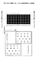
図2は、図1に示したの画像形成装置の機構部の平面図であり、図2に示すように、ヘッドアレイユニット5は、2列のヘッドユニット列を有し、1列当たり5個のヘッドユニット51を備えている。それぞれのヘッドユニット列の5個のヘッドユニット51は、用紙の主走査方向のほぼ全幅にわたって配列部材(保持部材)55上に固定配置されている。用紙搬送方向上流側のヘッドユニット列を第1列(a列ともいう。)として、ヘッドユニット51a1、51a2、51a3、51a4、51a5を備え、第2列(b列ともいう。)のヘッドユニット列には、ヘッドユニット51b1、51b2、51b3、51b4、51b5を備えている。そして、第1列と第2列の各ヘッドユニット51aと51bはそれぞれ交互に千鳥状に配置されている。なお、ヘッドユニットを総称する場合にはヘッドユニット51、各列のヘッドユニットを総称する場合には、例えばa列のヘッドユニット51は「ヘッドユニット51a」というように表記する。
FIG. 2 is a plan view of the mechanism portion of the image forming apparatus shown in FIG. 1. As shown in FIG. 2, the head array unit 5 has two head unit rows, and five head array rows per row. The
また、各ヘッドユニット51は複数のノズルを配列したノズル列を4列有しており、それぞれのノズル列には同じ色のインクを吐出する吐出ノズル、ノズル列で、イエロー(Y)ノズル列、マゼンタ(M)ノズル列、シアン(C)ノズル列、ブラック(K)ノズル列が配列されている。各ノズル列のノズルは、主走査方向(用紙の幅方向)に等間隔(この間隔を1ピッチとする。)に配列されており、隣り合うノズル列のノズルとは、主走査方向に1/2ピッチずつずれている。そして、この4列に配列された一組のノズルで1画素分のカラー画像を形成できる構成になっている。一方、モノクロ(黒又はグレー)画像形成時には、ブラックノズルとこれと1/2ピッチずつずれているノズルとが、それぞれ1画素分の画像を形成できる。この為、モノクロ(黒又はグレー)画像形成時には、主走査方向の印刷画像の画素密度は、カラー画像形成時の印刷画像の画素密度の2倍とすることができる。
Each
このヘッドアレイユニット5は、各ヘッドユニット51の上方に、各ヘッドユニット51に所要の色のインクを供給する分配器であるディストリビュータ52a〜52dが配置され、ディストリビュータ52とヘッドユニット51間は供給チューブ53にて接続されている。また、ディストリビュータ52にはサブタンク54が配置され、水頭差によりインクがヘッドユニット51のヘッドに供給される。さらに、サブタンク54の上流側には図示しないインクメインタンクが配置され、いずれも供給チューブを介してインクが供給される。
In the head array unit 5, distributors 52 a to 52 d that are distributors for supplying ink of a desired color to each
搬送ユニット4の下流側には用紙Pを排紙トレイ3に排紙する搬送ガイド部7が設けられている。搬送ガイド部7にて案内されて搬送される用紙Pは排紙トレイ3に排紙される。排紙トレイ3は、用紙Pの幅方向を規制する対のサイドフェンス31と用紙Pの先端を規制するエンドフェンス32を備えている。
On the downstream side of the transport unit 4, a transport guide portion 7 that discharges the paper P to the
維持回復機構(クリーニング装置)6は、ヘッドアレイユニット5の第1ないし第2列の各ヘッドユニット51に対応して、第1列ないし第2列に、それぞれ5個のクリーニング手段61a1〜61a5、61b1〜61b5が千鳥状に配置されている。なお、クリーニング装置6の各部の表記についてもヘッドアレイユニット5の場合と同様とする。
The maintenance / recovery mechanism (cleaning device) 6 corresponds to the
それぞれのクリーニング手段61の下部にはヘッドユニット51のヘッドからインクを吸引するための吸引ポンプ62(62a、62b)が配置されている。
Under each cleaning means 61, suction pumps 62 (62a, 62b) for sucking ink from the head of the
また、この画像形成装置においては、印刷終了後、液滴を吐出するヘッドユニット51のヘッドをクリーニング手段61でキャッピングした状態でノズルからインクを吸引する場合、あるいは、ヘッドユニット51のヘッドのノズル面に付着したインクをクリーニング手段61で清掃する場合は、印刷停止後、搬送ユニット4全体が搬送従動ローラ41bを支点に図1で矢印B方向に回動し、ヘッドアレイユニット5との間の空間を画像形成時よりも大きくすることで、ヘッドアレイユニット5の移動スペースを確保するようにしている。このとき、クリーニング装置6上部に配置されている搬送ガイド部7も支点71にて矢印C方向上方に回動され、クリーニング装置6の上方が開放される。
Further, in this image forming apparatus, after the printing is finished, when the ink of the
そして、搬送ユニット4と搬送ガイド部7がそれぞれ解放(解除)された後に、ヘッドアレイユニット5が用紙搬送方向(矢示A方向)に移動し、クリーニング装置6上方で停止され、クリーニング手段61が上昇して各ヘッドユニット51のヘッドのクリーニング動作(維持回復動作)に移行する。
Then, after the transport unit 4 and the transport guide portion 7 are released (released), the head array unit 5 moves in the paper transport direction (arrow A direction), stops above the cleaning device 6, and the cleaning means 61 The head moves up and shifts to the head cleaning operation (maintenance recovery operation) of each
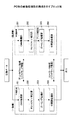
図3は、本発明の画像形成装置の制御部の構成を示すブロック図である。この制御部100は、装置全体の制御を司るCPU101と、CPU101が実行するプログラム、その他の固定データを格納するROM102と、画像データ等を一時格納するRAM103と、装置の電源が遮断されている間もデータを保持するための不揮発性メモリ(以下NVRAMと略す)104と、その他装置全体を制御するための入出力信号を処理するASIC105とを備えている。なお、ASIC105については、後述する「高速機」に分類される画像形成装置では、画像処理の一部を担当する機能が付与されている場合もある。
FIG. 3 is a block diagram showing the configuration of the control unit of the image forming apparatus of the present invention. The
この制御部100は、ホスト側とのデータ、信号の送受を行うためのホストI/F106と、各ヘッドユニット51を駆動制御するためのヘッド駆動制御部107及びヘッドドライバ108と、ヘッドアレイユニット移動モータ109を駆動するためのヘッドアレイ移動モータ駆動部110と、搬送ベルト移動モータ111を駆動するための搬送ベルト移動モータ駆動部112と、吸引ファン44に対する吸引ファンモータ116を駆動する吸引ファンモータ駆動部117と、環境温度及び/又は環境湿度を検出する環境センサ113及び図示しない各種センサからの検知信号を入力するためのI/O114などを備えている。
The
この制御部100には、この装置に必要な情報の入力及び表示を行うための操作パネル115が接続されている。
An
ここで、制御部100は、パーソナルコンピュータ(以下PCと称す。)等の情報処理装置、イメージスキャナなどの画像読み取り装置、デジタルカメラなどの撮像装置などのホスト側からの画像データを含む印刷データ等をケーブル或いはネットを介してホストI/F106で受信する。
Here, the
そして、CPU101は、ホストI/F106に含まれる受信バッファ内の印刷データを読み出して解析し、ASIC105にてデータの並び替え処理等(場合によっては、後述する画像処理の一部)を行ってヘッド駆動制御部107に画像データを転送する。なお、画像出力するための印刷データのビットマップデータ(印刷ラスタデータ)への変換は、例えばROM102にフォントデータを格納して行っても良いし、ホスト側のプリンタドライバーで画像データをビットマップデータに展開し印刷データのビットマップデータ(印刷ラスタデータ)を作成した上で、該印刷ラスタデータデータをこの装置に転送するようにしても良い。
Then, the CPU 101 reads out and analyzes the print data in the reception buffer included in the host I /
ヘッド駆動制御部107は、印刷ラスタデータデータを受け取ると、このドットパターンデータ(印刷ラスタデータデータ)を、クロック信号に同期して、ヘッドドライバ108にシリアルデータで送出し、また所定のタイミングでラッチ信号をヘッドドライバ108に送出する。
Upon receiving the print raster data data, the head
このヘッド駆動制御部107は、駆動波形(駆動信号)のパターンデータを格納したROM(ROM102で構成することもできる。)と、このROMから読出される駆動波形のデータをD/A変換するD/A変換器を含む波形生成回路及びアンプ等で構成される駆動波形発生回路を含む。
The head
また、ヘッドドライバ108は、ヘッド駆動制御部107からのクロック信号及び画像データであるシリアルデータを入力するシフトレジスタと、シフトレジスタのレジスト値をヘッド駆動制御部107からのラッチ信号でラッチするラッチ回路と、ラッチ回路の出力値をレベル変化するレベル変換回路(レベルシフタ)と、このレベルシフタでオン/オフが制御されるアナログスイッチアレイ(スイッチ手段)等を含み、アナログスイッチアレイのオン/オフを制御することで、駆動波形に含まれる所要の駆動波形を選択的にヘッドユニット51のアクチュエータ手段に印加して、ヘッドを駆動し、画像データを印刷してドットパターンラインを形成する。
The head driver 108 also receives a clock signal from the head
ホストPC側で行われる処理の一例として、図4を用いて説明を行う。図4では、全ての画像処理をPC側で処理する「一般機」(汎用的な画像処理装置)と、一部の処理を記録装置に内蔵したASICで分担する「高速機」とについて示している。この図で示すところの「高速機」では、画像処理をホスト側と記録装置側で分担して処理することができるため、画像処理にかかる時間を短縮できるだけでなく、ホストPCの開放を早めることができる
画像処理の概要は、入力された画像データをモニター表示用の色空間から記録装置用の色空間への変換(RGB表色系→CMY表色系)を行うCMM(Color Management Module)処理部201,301、CMYの値から黒生成/下色除去を行うBG/UCR(Black Generation/Under Color Removal)と、記録装置の特性やユーザの嗜好を反映した入出力補正を行うγ補正とを行うBG/UCR/γ補正部202,302、記録装置の解像度に合わせて拡大処理を行うズーミング(Zooming)処理部203,303、画像データを記録装置から噴射するドットのパターン配置に置き換える中間調処理(多値・少値マトリクス)部204,304より構成される。
An example of processing performed on the host PC side will be described with reference to FIG. FIG. 4 shows a “general machine” (general-purpose image processing apparatus) that processes all image processing on the PC side and a “high-speed machine” that shares a part of the processing with an ASIC built in the recording apparatus. Yes. In the "high speed machine" shown in this figure, image processing can be shared between the host side and the recording apparatus side, so that not only can the time required for image processing be shortened, but also the opening of the host PC can be accelerated. The outline of image processing is CMM (Color Management Module) processing that converts input image data from a color space for monitor display to a color space for a recording device (RGB color system → CMY color system)
本発明は、この内の画像データを記録装置から噴射するドットのパターン配置に置き換える処理に関する特徴を持つ。ここでは、本発明におけるモノクロ(黒又はグレー)画像の処理について説明する。 The present invention has a feature relating to a process for replacing the image data among them with a pattern arrangement of dots ejected from the recording apparatus. Here, processing of a monochrome (black or gray) image in the present invention will be described.
図5は、本発明の実施の形態例に係るインクジェット記録装置のライン型記録ヘッドの各ヘッドユニット51における、ノズルの配列の様子を示す平面図である。図5に示すように、本実施の形態例のインクジェット記録装置のヘッドユニット51におけるノズル列402は、用紙搬送方向(副走査方向)と略直角方向(主走査方向)にシアン(C)、ブラック(K)、マゼンタ(M)、イエロー(Y)の各色毎に1列に配列された4列で構成されている。そして、ヘッドユニット51の4列のノズル列402は、ブラック(K)のノズル列と、ブラック(K)のノズル列と用紙搬送方向で同一のラスタ位置(副走査線上に重なる位置)に配列されたイエロー(Y)のノズル列とから構成される第1のノズル列404と、シアン(C)のノズル列とマゼンタ(M)のノズル列が用紙搬送方向で同一のラスタ位置に配列され、かつ第1のノズル列404のノズルに対して、主走査方向に半ピッチずつずらして配列された第2のノズル列403とからなっている。
FIG. 5 is a plan view showing an arrangement of nozzles in each
なお、ノズルの使用する色は、ブラック(K)、シアン(C)、イエロー(Y)、マゼンタ(M)の4つの色に限らず、これ以外の色を加えてもよい。また、ヘッドユニット51上の色の配列順序は、図5に示す順序に限らない。更に、ブラックノズルの無いラスタのノズル(ここでは第2のノズル列403)は、ブラックドットの代替として擬似ブラックドットを形成するため、濃度が高く黒に近い色となるノズルの組み合わせが好ましい。その組み合わせによって、つまりシアン(C)、イエロー(Y)、マゼンタ(M)のいずれの2色とするかによって、代替ドットはシアン(C)とイエロー(Y)の場合緑系、シアン(C)とマゼンタ(M)の場合青系、イエロー(Y)とマゼンタ(M)の場合赤系のいずれかとなり、搭載するインクの特性にもよるが、一般的にはシアン(C)とマゼンタ(M)の組み合わせによる青系の構成が好ましい。
The colors used by the nozzles are not limited to the four colors of black (K), cyan (C), yellow (Y), and magenta (M), and other colors may be added. Further, the arrangement order of the colors on the
以下の説明では図5に示す配列のとおり、擬似ブラックドットがシアン(C)とマゼンタ(M)の青系となり、CKMYの順の配列として説明する。各ノズルの主走査方向の間隔1ピッチに対応する密度は150dpiである。図5に示すように、イエローノズル列はブラックノズル列と副走査方向に同じラスタ位置(同じ副走査線上)に配置され、シアンノルズ列とマゼンタノズル列はブラックノズル列から副走査方向に半ピッチ分、つまり300dpiずらしたラスタ位置に配置されている。 In the following description, as shown in the arrangement shown in FIG. 5, the pseudo black dots are cyan (C) and magenta (M) blue, and are described as an arrangement in the order of CKMY. The density corresponding to one pitch in the main scanning direction of each nozzle is 150 dpi. As shown in FIG. 5, the yellow nozzle row is arranged at the same raster position (on the same sub-scan line) as the black nozzle row, and the cyan nozzle row and the magenta nozzle row are half a pitch from the black nozzle row in the sub-scan direction. That is, they are arranged at raster positions shifted by 300 dpi.
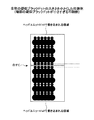
図6,図7を用いて、第一列のヘッドユニット列に属するヘッドユニット51a1と第二列のヘッドユニット列に属するヘッドユニット51b1による、従来の画像形成方法について説明する。図6、図7において、左図は、ヘッドユニット51a1とヘッドユニット51b1中のノズルの配列状況を示し、右図は、記録用紙上に書き込まれたモノクロ(黒又はグレー)画像を表す。モノクロ画像の上半分は、ヘッドユニット51b1により書き込まれ、下半分は、ヘッドユニット51a1により書き込まれた図である。なお、この画像は、1ドットが300dpiを示しており、副走査方向に6ドットパターンラインが書き込まれており、1回の画像形成では、1列のドットパターンライン画像が形成される。また、このヘッドアレイユニット(ライン型記録ヘッド)は、ヘッドユニット51a1、51b1に組み付け位置ずれが無い場合を示している。 A conventional image forming method using the head unit 51a1 belonging to the first head unit row and the head unit 51b1 belonging to the second head unit row will be described with reference to FIGS. 6 and 7, the left figure shows the arrangement of the nozzles in the head unit 51a1 and the head unit 51b1, and the right figure shows a monochrome (black or gray) image written on the recording paper. The upper half of the monochrome image is written by the head unit 51b1, and the lower half is written by the head unit 51a1. In this image, one dot indicates 300 dpi, and six dot pattern lines are written in the sub-scanning direction, and one dot pattern line image is formed in one image formation. Further, this head array unit (line type recording head) shows a case where the head units 51a1 and 51b1 have no assembly position deviation.
ブラックノズルの存在しないラスタのドット(ドットパターン)信号についてはシアンとマゼンタに割り当てる。これによりブラックノズルによるインク吐出に加え、300dpiずれた位置に配置されたシアンノズルとマゼンタノズルによる吐出も合わせて行われるため、ブラックインクで形成されるブラックドットからなるドットパターンと、シアンインクとマゼンタインクで形成される擬似ブラックドットからなるドットパターンとが交互に配置されることとなる。画像の黒(Kのドットパターン)の間隙のドット(C+Mのドットパターン)はシアンインクとマゼンタインクの混合により青に近い色となる。黒の隙間がブルーで埋まることによりグレーバランスが青寄りになるが、画像は300dpiの密度で形成され、画像の主走査方向の解像度は2倍となり、画像の濃度も濃くなる。ここで、K及びC+Mのドットパターンの交互配置方向は、ヘッドユニットの各色のノズル配置方向と同じ主走査方向である。 Raster dot (dot pattern) signals without black nozzles are assigned to cyan and magenta. As a result, in addition to the ink ejection by the black nozzle, the ejection by the cyan nozzle and the magenta nozzle arranged at a position shifted by 300 dpi is also performed, so that the dot pattern composed of black dots formed by the black ink, the cyan ink and the magenta Dot patterns composed of pseudo black dots formed of ink are alternately arranged. The dots (C + M dot pattern) in the black (K dot pattern) gap of the image have a color close to blue due to the mixture of cyan ink and magenta ink. Although the gray balance becomes closer to blue by filling the black gap with blue, the image is formed at a density of 300 dpi, the resolution of the image in the main scanning direction is doubled, and the density of the image is also increased. Here, the alternate arrangement direction of the K and C + M dot patterns is the same main scanning direction as the nozzle arrangement direction of each color of the head unit.
記録用紙上のヘッドユニット51a1に対向する位置(図の記録用紙の下側)に1ドットパターンライン分の画像を記録し、ヘッドユニット51b1に対向する位置(図の記録用紙の上側)にも1ドットパターンライン分の画像を記録する。そして、全体として、記録用紙の全幅にわたる1ドットパターンライン分の画像が得られる。このとき、ヘッドユニット51a1、51b1間に組み付け位置ずれがなければ、図6に示すように、記録用紙の全幅にわたる1ドットパターンライン分の画像に位置ずれが見られず、白すじの発生もない良好な画像が得られる。 An image for one dot pattern line is recorded at a position on the recording sheet facing the head unit 51a1 (lower side of the recording sheet in the figure), and 1 is also recorded at a position facing the head unit 51b1 (upper side of the recording sheet in the figure). Records an image of dot pattern lines. As a whole, an image for one dot pattern line over the entire width of the recording paper is obtained. At this time, if there is no assembly position deviation between the head units 51a1 and 51b1, as shown in FIG. 6, there is no position deviation in the image of one dot pattern line over the entire width of the recording paper, and no white streak occurs. A good image is obtained.
なお、従来の画像形成装置においては、ヘッドユニット51a1とヘッドユニット51b1とにほとんど重複部がなく、ノズルの重なり(重複ノズル)がないヘッドアレイユニットを使用していた。また、例え、図6に示すように、ヘッドユニット51a1とヘッドユニット51b1とにノズルの重なりがあっても、別々のヘッドユニットに配列された同じラスタのノズルが、同じ印刷ラスタデータを基に、それぞれインクを吐出して同じ位置の画像(画素)を形成することはなかった。図6の例では、ヘッドユニット51a1のシアン(C)ノズル列と、マゼンタ(M)ノズル列の最上部のノズルと、ヘッドユニット51b1のブラック(K)ノズル列と、イエロー(Y)ノズル列の最下部のノズルとは、ともにインク吐出をしないダミーノズルの構成となっていた。 In the conventional image forming apparatus, a head array unit in which the head unit 51a1 and the head unit 51b1 have almost no overlapping portion and no nozzle overlap (overlapping nozzle) has been used. For example, as shown in FIG. 6, even if there is an overlap of nozzles in the head unit 51a1 and the head unit 51b1, nozzles of the same raster arranged in different head units are based on the same print raster data. Ink was not ejected to form an image (pixel) at the same position. In the example of FIG. 6, the cyan (C) nozzle row of the head unit 51a1, the uppermost nozzle of the magenta (M) nozzle row, the black (K) nozzle row of the head unit 51b1, and the yellow (Y) nozzle row. The lowermost nozzle is a dummy nozzle that does not discharge ink.
図7に示すヘッドアレイユニットは、ヘッドユニット51a1に組み付け位置ずれがあり、ヘッドユニット51b1との間にノズルが離間する方向に組み付いている例を示す。この場合、ヘッドユニット51a1で記録される画像領域の上端部の画像と、ヘッドユニット51b1で記録される画像領域下端部の画像とが離間して記録されるため、画像形成を続けると、上部の画像領域と下部の画像領域との間に、副走査方向に沿って非画像形成領域(白すじ)が発生することがあり、好ましくない画像品質となる。 The head array unit shown in FIG. 7 shows an example in which the head unit 51a1 has an assembly position shift and is assembled in a direction in which the nozzles are separated from the head unit 51b1. In this case, the image at the upper end of the image area recorded by the head unit 51a1 and the image at the lower end of the image area recorded by the head unit 51b1 are recorded separately. A non-image forming area (white streak) may occur between the image area and the lower image area in the sub-scanning direction, resulting in an undesirable image quality.
本発明の画像形成装置においては、図8のヘッドユニット51a1、51b1のノズルの配置図に示すように、ヘッドユニット51a1とヘッドユニット51b1の重なり部におけるノズルの副走査方向のオーバーラップ部では、ヘッドユニット51a1に属するノズルと、ヘッドユニット51b1に属するノズルで同じ副走査線上に配置された(組み付けの位置ずれは無視する。)ノズルとで、記録用紙上に1画素の画像(ドット)を形成する吐出ノズルに割り当てる。すなわち、本発明の画像形成装置においては、別々のヘッドユニットに配列された同じラスタのノズルが、同じ印刷ラスタデータを基に、それぞれインクを吐出して略同一領域に画像(ドット)を形成する。これらのノズルを互いに重複ノズルという。 In the image forming apparatus of the present invention, as shown in the nozzle arrangement diagram of the head units 51a1 and 51b1 in FIG. 8, in the overlapping portion of the nozzle in the sub-scanning direction at the overlapping portion of the head unit 51a1 and the head unit 51b1, An image (dot) of one pixel is formed on the recording paper by the nozzle belonging to the unit 51a1 and the nozzle belonging to the head unit 51b1 arranged on the same sub-scan line (ignoring misalignment of assembly). Assign to the discharge nozzle. In other words, in the image forming apparatus of the present invention, nozzles of the same raster arranged in different head units eject inks based on the same print raster data to form images (dots) in substantially the same area. . These nozzles are called overlapping nozzles.
図8の例に従って説明すれば、ヘッドユニット51b1のシアン(C)ノズル列に属する最下段のシアンカラーノズルと、ヘッドユニット51a1のマゼンタ(M)ノズル列に属する最上段のマゼンタカラーノズルとは、記録用紙上のヘッドユニット51a1とヘッドユニット51b1との記録領域が重なる位置の画像を形成する。なお、この画像(ドット)は、ヘッドユニット51a1の組み付け位置ずれによって、厳密にはヘッドユニット51a1のドットとヘッドユニット51b1のドットとがずれて、1画素分の画像(ドット)を形成している。しかし、その上下両側にブラックドットが配置されているため、ヘッドユニット51a1の組み付け位置ずれが許容値以下であれば、白すじは発生せず、画像品質には影響がない。 Referring to the example of FIG. 8, the lowermost cyan color nozzle belonging to the cyan (C) nozzle row of the head unit 51b1 and the uppermost magenta color nozzle belonging to the magenta (M) nozzle row of the head unit 51a1 are: An image is formed at a position where the recording areas of the head unit 51a1 and the head unit 51b1 overlap on the recording paper. This image (dot) forms an image (dot) corresponding to one pixel by strictly shifting the dot of the head unit 51a1 and the dot of the head unit 51b1 due to the displacement of the assembly position of the head unit 51a1. . However, since black dots are arranged on both the upper and lower sides thereof, white streaks do not occur and the image quality is not affected if the assembly position deviation of the head unit 51a1 is less than the allowable value.
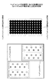
本発明の画像形成装置として、グレーバランスが青寄りになるのを防ぐ方法として、ブラックドットに較べて擬似ブラックドットの吐出量を相対的に減らすことが好ましい。図9Aは、擬似ブラックドットのドットパターンを形成するシアンとマゼンタのインク吐出量を少なくし、ブラックドットのドットパターンのうちブラックのインク吐出量を多くした画像例を示す。擬似ブラックドットのドットパターンを形成するシアンとマゼンタの吐出量が少なくなると、画像全体に占めるブラックドットの面積割合が増えるので、良好なモノクロ(黒又はグレー)画像となる。 In the image forming apparatus of the present invention, as a method for preventing the gray balance from being close to blue, it is preferable to relatively reduce the discharge amount of the pseudo black dots compared to the black dots. FIG. 9A shows an image example in which the cyan and magenta ink ejection amounts forming the pseudo black dot dot pattern are reduced and the black ink ejection amount is increased in the black dot dot pattern. When the discharge amount of cyan and magenta forming the pseudo black dot pattern is reduced, the area ratio of the black dots in the entire image increases, so that a good monochrome (black or gray) image is obtained.
しかし、図10Aに示すように、「白すじを発生させない許容組み付け位置ずれ量」は「擬似ブラックドットを形成するシアンとマゼンタのドット径の和」までとなるため、擬似ブラックドットを形成するカラーインクのドット径が小さくなると、おのずと白すじを発生させないための「白すじを発生させない許容組み付け位置ずれ量」も小さくなる。 However, as shown in FIG. 10A, the “allowable assembling position deviation amount that does not generate white streaks” is up to “the sum of the cyan and magenta dot diameters that form pseudo black dots”. When the dot diameter of the ink is reduced, the “allowable assembling position deviation amount that does not cause white streaks” for naturally preventing white streaks is also reduced.
これに対し、図9B、図10Bに示すように、ヘッドユニット51a1とヘッドユニット51b1の両方の重複ノズルから吐出されたインクが形成する、書き込み領域のオーバーラップ部における画像の擬似ブラックドットのドット径を、ノズルがオーバーラップしていない書き込み領域を形成する擬似ブラックドットのドット径より大きくすることで、全体の擬似ブラックドットの吐出量を抑えて全体のグレーバランスを整えた場合においても、十分な組み付け位置ずれ許容量を確保できる。さらに、図10Cに示すように、擬似ブラックドットを構成するユニット51a1及びヘッドユニット51b1から吐出される個々のドットの大きさを交互に変える構成とすることもできる。
On the other hand, as shown in FIG. 9B and FIG. 10B, the dot diameter of the pseudo black dot of the image in the overlap portion of the writing area formed by the ink ejected from the overlapping nozzles of both the head unit 51 a 1 and the head unit 51
重複ノズルから吐出されたインクが形成する、書き込み領域のオーバーラップ部における画像が画像端部を形成する場合の好ましい処理について説明する。図11A〜図12は、画像端部がヘッドユニット51a1の書き込み領域と、ヘッドユニット51b1の書き込み領域とのオーバーラップ部となった場合についての説明図である。図11A〜図11Cに示す印刷例では、ヘッドユニット51b1の書き込み領域で画像形成が終了している。なお、図における白抜きの丸は、ヘッドユニット51a1による仮想の画像形成位置で、画像が形成されていないことを表している。 A description will be given of a preferable process in the case where the image formed in the overlapping portion of the writing area formed by the ink ejected from the overlapping nozzle forms the image end portion. FIG. 11A to FIG. 12 are explanatory diagrams in the case where the image end portion is an overlap portion between the writing area of the head unit 51a1 and the writing area of the head unit 51b1. In the printing examples shown in FIGS. 11A to 11C, image formation is completed in the writing area of the head unit 51b1. The white circle in the figure indicates that no image is formed at a virtual image forming position by the head unit 51a1.
図11Aは、ヘッドユニット51a1とヘッドユニット51b1とに組み付け位置ずれが起こっておらず、画像端部が正常に印刷されている状態を示す。この場合は、上記のように、ヘッドユニット51a1とヘッドユニット51b1との重複ノズルからそれぞれマゼンタとシアンのインクを吐出して、画像端部の画像(ドット)を形成しても何の問題もない。 FIG. 11A shows a state in which the assembly position is not shifted between the head unit 51a1 and the head unit 51b1, and the image end portion is normally printed. In this case, as described above, there is no problem even if the magenta and cyan inks are respectively ejected from the overlapping nozzles of the head unit 51a1 and the head unit 51b1 to form an image (dot) at the edge of the image. .
しかし、ヘッドユニット51a1とヘッドユニット51b1とに組み付け位置ずれが起こってオーバーラップ部が広くなっている場合には、図11Bに示すように、白すじの発生まではなくても、画像端部の疑似ブラックドットの幅が広くなる。画像端部において、疑似ブラックドットの幅が広くなり、かつブラックドットに隣接しないと、モノクロ画像における疑似ブラックドットの色味や明度の違いが目立ちやすくなり、画像品質上好ましくない。 However, when the assembly position shift occurs between the head unit 51a1 and the head unit 51b1 and the overlap portion is widened, as shown in FIG. The width of the pseudo black dot becomes wider. If the width of the pseudo black dot is wide and not adjacent to the black dot at the edge of the image, the difference in color and brightness of the pseudo black dot in the monochrome image tends to be noticeable, which is not preferable in terms of image quality.
そこで、画像端部がヘッドユニット51の書き込み領域のオーバーラップ部に重なった場合は、図11Cに示すように、画像形成領域でなくなる領域に対応するヘッドユニット51(図11Cにおいては、ヘッドユニット51a1)に属する重複ノズルから吐出されるべきインクは、吐出しないことが好ましい。更には、ヘッドユニット51b1のシアンノズルと同一ラスタにあるヘッドユニット51bマゼンタノズルからマゼンタインクを吐出することが好ましい。そうすれば、画像端部には、ヘッドユニット51b1に属する重複ノズルからだけインクドットが吐出され、図11Bに示すような幅の広い疑似ブラックドットによる画像端部は形成されない。このようにして、画像端部における画像品質を向上させることができる。なお、画像の下側端部を対象に説明下が、画像の上側端部についても同じようにすればよい。
Therefore, when the image end portion overlaps the overlap portion of the writing area of the
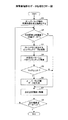
図12は、画像端部と書き込み領域のオーバーラップ部が重なった場合の、制御部におけるデータ処理のフロー図を示している。図12を参照にして、オーバーラップ部のデータ処理について説明する。まず、オーバーラップ部の先頭位置を注目画素とする(ステップS1)。注目画素は画像部か否かを判断し(ステップS2)、画像部でなければ(ステップS2のN)、次の位置に注目画素を移動する(ステップS7)。画像部であれば(ステップS2のY)、ウィンドウに相当するビットマップデータを取得する(ステップS3)。そして、所定のパターンとマッチングをし(ステップS4)、マッチすれば(ステップS5のY)、オーバーラップ部データを生成し(ステップS6)、次の位置に注目画素を移動する(ステップS7)。所定のパターンとマッチしなければ(ステップS5のN)、そのまま次の位置に注目画素を移動する(ステップS7)。そして、次の注目画素がオーバーラップ部のデータエンドでなければ(ステップS8のN)、ステップS2に戻って次の注目画素に対して、同じようにステップS2からステップS7のオーバーラップ部のデータ生成と注目画素の移動を繰り返す。注目画素がデータエンドであれば(ステップS8のY)終了となる。 FIG. 12 shows a flow chart of data processing in the control unit when the image edge and the overlap part of the writing area overlap. With reference to FIG. 12, the data processing of the overlap part will be described. First, the top position of the overlap portion is set as a target pixel (step S1). It is determined whether or not the target pixel is an image portion (step S2). If it is not an image portion (N in step S2), the target pixel is moved to the next position (step S7). If it is an image portion (Y in step S2), bitmap data corresponding to the window is acquired (step S3). Then, matching is performed with a predetermined pattern (step S4), and if matched (Y in step S5), overlap portion data is generated (step S6), and the target pixel is moved to the next position (step S7). If it does not match the predetermined pattern (N in step S5), the target pixel is moved to the next position as it is (step S7). If the next pixel of interest is not the data end of the overlap portion (N in step S8), the process returns to step S2 and the data of the overlap portion in steps S2 to S7 is similarly applied to the next pixel of interest. Repeat generation and movement of target pixel. If the pixel of interest is a data end (Y in step S8), the process ends.
なお、オーバーラップ部のデータ生成においては、注目画素が画像端部ではなく、隣接画素にブラックドットが両方とも存在する場合は所定のパターンとパターンマッチングするようにし、オーバーラップ部データを生成し、オーバーラップ部の擬似ブラックドットを2つのヘッドユニットにより形成するように制御する。注目画素が画像端部となっている場合は、オーバーラップ部データは生成せず、画像の存在する側のノズルだけで擬似ブラックドットを形成する。 In the overlap portion data generation, if the target pixel is not the image end portion and both the black dots exist in the adjacent pixels, pattern matching with a predetermined pattern is performed, and overlap portion data is generated, Control is performed so that the pseudo black dots in the overlap portion are formed by two head units. If the pixel of interest is at the edge of the image, the overlap portion data is not generated, and a pseudo black dot is formed only by the nozzle on the side where the image exists.
異なるヘッドユニット列の隣接するヘッドユニットにおける、ノズル列の変更やノズル配置の変更、重複ノズルの組合せの変更について説明する。図13は、図5に示したヘッドユニットのノズル列の配列を変更している。すなわち、ノズル列を右端から、ブラックノズル列、シアンノズル列、マゼンタノズル列、イエローノズル列の順にしている。そして、ブラックノズルとマゼンタノズルが同じラスタ位置に配置され、これらとノズルの配置ピッチで半ピッチずらしたラスタ位置にシアンノズルとイエローノズルを配置している。この為、重複ノズルの組合せとすることができるのは、ブラックノズルとマゼンタノズル又は、シアンノズルとイエローノズルである。 A description will be given of a change in nozzle row, a change in nozzle arrangement, and a change in combination of overlapping nozzles in adjacent head units of different head unit rows. FIG. 13 changes the arrangement of the nozzle rows of the head unit shown in FIG. That is, the nozzle row is arranged from the right end in the order of the black nozzle row, the cyan nozzle row, the magenta nozzle row, and the yellow nozzle row. The black nozzle and the magenta nozzle are arranged at the same raster position, and the cyan nozzle and the yellow nozzle are arranged at a raster position shifted by a half pitch from the nozzle arrangement pitch. For this reason, a combination of overlapping nozzles can be a black nozzle and a magenta nozzle or a cyan nozzle and a yellow nozzle.
ここで、重複ノズルの組合せの一方にブラックノズルを使用すると、これまでの説明と同様に白すじは発生せず好ましいモノクロ画像が得られる。 Here, when a black nozzle is used for one of the overlapping nozzle combinations, a white and black streak does not occur as described above, and a preferable monochrome image can be obtained.
図14では、図5に示したヘッドユニットのノズル列の配列を図13とは別の形態に変更している。すなわち、ノズル列の配列は図5に示すヘッドユニットと同じであるが、ブラックノズル配置ピッチに対し、半ピッチずらしたラスタ位置にシアンノズルとマゼンタノズルとイエローノズルを配置している。この為、シアンノズルとマゼンタノズルとイエローノズルを重複ノズルの組合せとすることができ、重複ノズルの組合せとしては、例えば、シアンノズルとマゼンタノズルとイエローノズルの3つを組合せた最大6個の重複ノズルの組合せ、シアンノズルとマゼンタノズル、シアンノズルとイエローノズルの組合せ、同じ色同士のノズルの組合せなどから選ぶことができる。 In FIG. 14, the arrangement of the nozzle rows of the head unit shown in FIG. 5 is changed to a form different from that shown in FIG. That is, the arrangement of the nozzle rows is the same as that of the head unit shown in FIG. 5, but cyan nozzles, magenta nozzles, and yellow nozzles are arranged at raster positions shifted by a half pitch with respect to the black nozzle arrangement pitch. For this reason, the cyan nozzle, the magenta nozzle, and the yellow nozzle can be used as a combination of overlapping nozzles. As the combination of overlapping nozzles, for example, a maximum of 6 overlapping nozzles including a combination of cyan, magenta, and yellow nozzles can be used. A combination of nozzles, a cyan nozzle and a magenta nozzle, a combination of a cyan nozzle and a yellow nozzle, a combination of nozzles of the same color, and the like can be selected.
シアンノズルとマゼンタノズルとイエローノズルの3つを組合せた重複ノズルとして、疑似ブラックインクドットを形成すれば、ブラックインクドットに近い色味や明度が達成できるので、品質の高いモノクロ画像が得られる。さらに、吐出するノズルの属するインクヘッドを選択することにより、これら3色のインクの組合せを画素単位で変更することが可能である。これらの色は、周囲の画像の状況や、画像形成における要求により変更すればよい。ここでは、シアンとマゼンタ+イエローのドットを2列のドットパターンライン分ずつ交互に形成した例(図15参照)、及びシアン、マゼンタ、イエロー、マゼンタ+イエロー、シアン+イエロー、及びマゼンタ+シアンが順に表層に形成されたドットの例(図16参照)を示した。このようにして、白すじを目立ちにくくすることもできる。 If pseudo black ink dots are formed as overlapping nozzles combining the cyan nozzle, the magenta nozzle, and the yellow nozzle, the color and brightness close to that of the black ink dots can be achieved, and a high quality monochrome image can be obtained. Furthermore, by selecting the ink head to which the nozzle to be ejected belongs, the combination of these three colors of ink can be changed in units of pixels. These colors may be changed according to the situation of the surrounding image and a request in image formation. In this example, cyan and magenta + yellow dots are alternately formed for two dot pattern lines (see FIG. 15), and cyan, magenta, yellow, magenta + yellow, cyan + yellow, and magenta + cyan Examples of dots formed on the surface layer in order (see FIG. 16) are shown. In this way, white lines can be made inconspicuous.
特ににじみにくい被記録媒体上への記録では、ヘッド組みつけずれが目立ちやすい傾向にあるが、複数ある重複ノズルの組合せから、上記のように所定タイミング(時間や距離、滴数)で、その組合せを切り換えることで、この位置ずれを目立ちにくくすることができる。更に略同一位置に3色のインクを吐出することで、ほぼブラックに近い疑似ブラックドットとすることもできる。 In particular, when recording on a recording medium that is difficult to bleed, misalignment of the head tends to be conspicuous. From the combination of a plurality of overlapping nozzles, the combination at a predetermined timing (time, distance, number of drops) as described above. This misalignment can be made inconspicuous by switching. Furthermore, by ejecting three colors of ink at substantially the same position, pseudo black dots that are almost black can be obtained.
1 :装置本体(画像形成装置)
2 :給紙トレイ
3 :排紙トレイ
4 :搬送ユニット
5 :ヘッドアレイユニット
6 :クリーニング装置
7 :搬送ガイド部
21 :分離ローラ
22 :給紙ローラ
31 :サイドフェンス
32 :エンドフェンス
41a :搬送駆動ローラ
41b :搬送従動ローラ
42a,42b :搬送ガイドローラ
43 :搬送ベルト
44 :吸引ファン
51 :ヘッドユニット
51a,51a1,51a2,51a3,51a4,51a5 :ヘッドユニット(a列)
51b,51b1,51b2,51b3,51b4,51b5 :ヘッドユニット(b列)
52,52a,52b,52c,52d :ディストリビュータ
53 :供給チューブ
54 :サブタンク
55 :配列部材(保持部材)
61,61a〜61a5,61b1〜61b5 :クリーニング手段
62,62a,62b :吸引ポンプ
1: Device main body (image forming apparatus)
2: Paper feed tray 3: Paper discharge tray 4: Transport unit 5: Head array unit 6: Cleaning device 7: Transport guide unit 21: Separation roller 22: Paper feed roller 31: Side fence 32: End fence 41a:
51b, 51b1, 51b2, 51b3, 51b4, 51b5: head unit (row b)
52, 52a, 52b, 52c, 52d: Distributor 53: Supply tube 54: Sub tank 55: Array member (holding member)
61, 61a-61a5, 61b1-61b5: Cleaning means 62, 62a, 62b: Suction pump
Claims (6)
前記ライン型記録ヘッドは、主走査方向に沿って配置された複数のヘッドユニットを備え、
前記複数のヘッドユニットのうち、主走査方向に隣接するヘッドユニットは、副走査方向に一部重複している重複領域を有し、
モノクロ画像を形成する場合は、前記重複領域において、一方のヘッドユニットの端部のカラーノズルからの吐出インクと、他方のヘッドユニットの端部のカラーノズルからの吐出インクは、前記記録媒体上で重複して疑似ブラックドットを形成することを特徴とする画像形成装置。 An image forming apparatus capable of forming a color image and a monochrome image by discharging ink onto the recording medium from a line-type recording head disposed opposite to the recording medium conveyed in the sub-scanning direction,
The line-type recording head includes a plurality of head units arranged along the main scanning direction ,
Among the plurality of head units, a head unit adjacent in the main scanning direction has an overlapping region that partially overlaps in the sub-scanning direction,
When a monochrome image is formed, in the overlap region, the ink ejected from the color nozzle at the end of one head unit and the ink ejected from the color nozzle at the end of the other head unit are on the recording medium. An image forming apparatus characterized by forming pseudo black dots overlappingly .
前記ライン型記録ヘッドは、主走査方向に沿って配置された複数のヘッドユニットを備え、
前記複数のヘッドユニットのうち、主走査方向に隣接するヘッドユニットは、副走査方向に一部重複している重複領域を有し、
前記重複領域において、一方のヘッドユニットの端部のカラーノズルからの吐出インクと、他方のヘッドユニットの端部のカラーノズルからの吐出インクを前記記録媒体上で重複させて疑似ブラックドットを形成することを特徴とする画像形成方法。 Image formation in which a monochrome image is formed by a device capable of forming a color image and a monochrome image by ejecting ink onto the recording medium from a line-type recording head disposed opposite to the recording medium conveyed in the sub-scanning direction A method,
The line-type recording head includes a plurality of head units arranged along the main scanning direction,
Among the plurality of head units, a head unit adjacent in the main scanning direction has an overlapping region that partially overlaps in the sub-scanning direction,
In the overlapping area, the ink ejected from the color nozzle at the end of one head unit and the ink ejected from the color nozzle at the end of the other head unit are overlapped on the recording medium to form pseudo black dots. An image forming method.
Priority Applications (1)
| Application Number | Priority Date | Filing Date | Title |
|---|---|---|---|
| JP2008237134A JP5343469B2 (en) | 2008-09-16 | 2008-09-16 | Image forming apparatus and image forming method |
Applications Claiming Priority (1)
| Application Number | Priority Date | Filing Date | Title |
|---|---|---|---|
| JP2008237134A JP5343469B2 (en) | 2008-09-16 | 2008-09-16 | Image forming apparatus and image forming method |
Publications (3)
| Publication Number | Publication Date |
|---|---|
| JP2010069640A JP2010069640A (en) | 2010-04-02 |
| JP2010069640A5 JP2010069640A5 (en) | 2011-10-20 |
| JP5343469B2 true JP5343469B2 (en) | 2013-11-13 |
Family
ID=42201888
Family Applications (1)
| Application Number | Title | Priority Date | Filing Date |
|---|---|---|---|
| JP2008237134A Expired - Fee Related JP5343469B2 (en) | 2008-09-16 | 2008-09-16 | Image forming apparatus and image forming method |
Country Status (1)
| Country | Link |
|---|---|
| JP (1) | JP5343469B2 (en) |
Families Citing this family (4)
| Publication number | Priority date | Publication date | Assignee | Title |
|---|---|---|---|---|
| JP2014004780A (en) * | 2012-06-26 | 2014-01-16 | Riso Kagaku Corp | Inkjet printer |
| DE102013007294A1 (en) * | 2013-04-26 | 2014-10-30 | Heidelberger Druckmaschinen Ag | Method for producing a printed image composed of sections |
| JP2015044386A (en) * | 2013-08-29 | 2015-03-12 | 理想科学工業株式会社 | Inkjet printing device |
| JP6141166B2 (en) * | 2013-09-30 | 2017-06-07 | 理想科学工業株式会社 | Inkjet printing device |
Family Cites Families (3)
| Publication number | Priority date | Publication date | Assignee | Title |
|---|---|---|---|---|
| JP4350327B2 (en) * | 2000-08-28 | 2009-10-21 | 富士フイルム株式会社 | Image recording apparatus and image recording method |
| JP4298486B2 (en) * | 2003-12-03 | 2009-07-22 | キヤノン株式会社 | Recording apparatus, recording method thereof, and program |
| JP2007030198A (en) * | 2005-07-22 | 2007-02-08 | Ricoh Co Ltd | Image forming method, program for executing image forming method and ink jet recorder |
-
2008
- 2008-09-16 JP JP2008237134A patent/JP5343469B2/en not_active Expired - Fee Related
Also Published As
| Publication number | Publication date |
|---|---|
| JP2010069640A (en) | 2010-04-02 |
Similar Documents
| Publication | Publication Date | Title |
|---|---|---|
| JP5347300B2 (en) | Printing device | |
| US7954923B2 (en) | Liquid ejecting apparatus and liquid ejecting method | |
| JP5123519B2 (en) | Printing apparatus and printing method | |
| JP2001001510A (en) | Printing apparatus, printing method, and recording medium | |
| JP2011031611A (en) | Recorder and program | |
| US20060092221A1 (en) | Printing method and apparatus for an ink-jet printer having a wide printhead | |
| JP2011016377A (en) | Printing which is performed up to end section of printing medium without soiling platen | |
| JP2003063043A (en) | Ink jet printer | |
| JP2005178042A (en) | Printing apparatus, computer program, printing system, and ink droplet ejection method | |
| JP4206706B2 (en) | Printing to the end of the printing paper without soiling the platen | |
| JP4619611B2 (en) | Bidirectional printing using two nozzle group sets arranged in reverse order | |
| JP5487552B2 (en) | Liquid ejection device and liquid ejection method | |
| JP5468633B2 (en) | Inkjet recording apparatus, image processing apparatus and method, and program | |
| JPH11208029A (en) | Printing apparatus, printing method, and recording medium | |
| JP5343469B2 (en) | Image forming apparatus and image forming method | |
| JP7027796B2 (en) | Printing device and printing control device | |
| KR20090013673A (en) | Inkjet image forming apparatus and control method thereof | |
| JP2011056705A (en) | Image forming apparatus | |
| US20100328376A1 (en) | Image recording device | |
| JP4765266B2 (en) | Printing apparatus, printing method, and program | |
| JP2009131959A (en) | Image forming method and image forming apparatus | |
| JP4244781B2 (en) | Printing to the end of the printing paper without soiling the platen | |
| JP4635374B2 (en) | Printing to the end of the print media without soiling the platen | |
| JP7020211B2 (en) | Data output setting adjustment method, image data processing device and image forming device | |
| JP4487496B2 (en) | Printing apparatus, printing system, and ink droplet ejection method |
Legal Events
| Date | Code | Title | Description |
|---|---|---|---|
| A521 | Written amendment |
Free format text: JAPANESE INTERMEDIATE CODE: A523 Effective date: 20110902 |
|
| A621 | Written request for application examination |
Free format text: JAPANESE INTERMEDIATE CODE: A621 Effective date: 20110902 |
|
| A131 | Notification of reasons for refusal |
Free format text: JAPANESE INTERMEDIATE CODE: A131 Effective date: 20121120 |
|
| A977 | Report on retrieval |
Free format text: JAPANESE INTERMEDIATE CODE: A971007 Effective date: 20121121 |
|
| A521 | Written amendment |
Free format text: JAPANESE INTERMEDIATE CODE: A523 Effective date: 20130121 |
|
| TRDD | Decision of grant or rejection written | ||
| A01 | Written decision to grant a patent or to grant a registration (utility model) |
Free format text: JAPANESE INTERMEDIATE CODE: A01 Effective date: 20130716 |
|
| A61 | First payment of annual fees (during grant procedure) |
Free format text: JAPANESE INTERMEDIATE CODE: A61 Effective date: 20130729 |
|
| R151 | Written notification of patent or utility model registration |
Ref document number: 5343469 Country of ref document: JP Free format text: JAPANESE INTERMEDIATE CODE: R151 |
|
| LAPS | Cancellation because of no payment of annual fees |