JP4553975B2 - Peak detection and clutter reduction for microwave sensors - Google Patents
Peak detection and clutter reduction for microwave sensors Download PDFInfo
- Publication number
- JP4553975B2 JP4553975B2 JP2009513292A JP2009513292A JP4553975B2 JP 4553975 B2 JP4553975 B2 JP 4553975B2 JP 2009513292 A JP2009513292 A JP 2009513292A JP 2009513292 A JP2009513292 A JP 2009513292A JP 4553975 B2 JP4553975 B2 JP 4553975B2
- Authority
- JP
- Japan
- Prior art keywords
- blade
- antenna
- phase
- data
- microwave
- Prior art date
- Legal status (The legal status is an assumption and is not a legal conclusion. Google has not performed a legal analysis and makes no representation as to the accuracy of the status listed.)
- Expired - Fee Related
Links
Images


Classifications
-
- F—MECHANICAL ENGINEERING; LIGHTING; HEATING; WEAPONS; BLASTING
- F01—MACHINES OR ENGINES IN GENERAL; ENGINE PLANTS IN GENERAL; STEAM ENGINES
- F01D—NON-POSITIVE DISPLACEMENT MACHINES OR ENGINES, e.g. STEAM TURBINES
- F01D21/00—Shutting-down of machines or engines, e.g. in emergency; Regulating, controlling, or safety means not otherwise provided for
- F01D21/003—Arrangements for testing or measuring
-
- G—PHYSICS
- G01—MEASURING; TESTING
- G01S—RADIO DIRECTION-FINDING; RADIO NAVIGATION; DETERMINING DISTANCE OR VELOCITY BY USE OF RADIO WAVES; LOCATING OR PRESENCE-DETECTING BY USE OF THE REFLECTION OR RERADIATION OF RADIO WAVES; ANALOGOUS ARRANGEMENTS USING OTHER WAVES
- G01S13/00—Systems using the reflection or reradiation of radio waves, e.g. radar systems; Analogous systems using reflection or reradiation of waves whose nature or wavelength is irrelevant or unspecified
- G01S13/02—Systems using reflection of radio waves, e.g. primary radar systems; Analogous systems
- G01S13/50—Systems of measurement based on relative movement of target
- G01S13/505—Systems of measurement based on relative movement of target using Doppler effect for determining closest range to a target or corresponding time, e.g. miss-distance indicator
-
- G—PHYSICS
- G01—MEASURING; TESTING
- G01S—RADIO DIRECTION-FINDING; RADIO NAVIGATION; DETERMINING DISTANCE OR VELOCITY BY USE OF RADIO WAVES; LOCATING OR PRESENCE-DETECTING BY USE OF THE REFLECTION OR RERADIATION OF RADIO WAVES; ANALOGOUS ARRANGEMENTS USING OTHER WAVES
- G01S13/00—Systems using the reflection or reradiation of radio waves, e.g. radar systems; Analogous systems using reflection or reradiation of waves whose nature or wavelength is irrelevant or unspecified
- G01S13/88—Radar or analogous systems specially adapted for specific applications
-
- G—PHYSICS
- G01—MEASURING; TESTING
- G01S—RADIO DIRECTION-FINDING; RADIO NAVIGATION; DETERMINING DISTANCE OR VELOCITY BY USE OF RADIO WAVES; LOCATING OR PRESENCE-DETECTING BY USE OF THE REFLECTION OR RERADIATION OF RADIO WAVES; ANALOGOUS ARRANGEMENTS USING OTHER WAVES
- G01S7/00—Details of systems according to groups G01S13/00, G01S15/00, G01S17/00
- G01S7/02—Details of systems according to groups G01S13/00, G01S15/00, G01S17/00 of systems according to group G01S13/00
- G01S7/41—Details of systems according to groups G01S13/00, G01S15/00, G01S17/00 of systems according to group G01S13/00 using analysis of echo signal for target characterisation; Target signature; Target cross-section
- G01S7/415—Identification of targets based on measurements of movement associated with the target
-
- F—MECHANICAL ENGINEERING; LIGHTING; HEATING; WEAPONS; BLASTING
- F05—INDEXING SCHEMES RELATING TO ENGINES OR PUMPS IN VARIOUS SUBCLASSES OF CLASSES F01-F04
- F05D—INDEXING SCHEME FOR ASPECTS RELATING TO NON-POSITIVE-DISPLACEMENT MACHINES OR ENGINES, GAS-TURBINES OR JET-PROPULSION PLANTS
- F05D2250/00—Geometry
- F05D2250/20—Three-dimensional
Description
[関連出願]出願人は、先に出願された仮特許出願である「高調波および速度フィルタリングに基づくピーク摘み取り」と題され、2006年6月1日に出願された、米国仮特許出願第60/810,105号への35U.S.C.119の下での優先権を主張する。この仮特許出願によって開示された主題はここに引用によって本出願内に完全に組み込まれる。 [Related Applications] Applicants have filed US Provisional Patent Application No. 60, filed June 1, 2006, entitled “Peak Picking Based on Harmonic and Velocity Filtering”, a previously filed provisional patent application. / U. S. C. Claim priority under 119. The subject matter disclosed by this provisional patent application is hereby fully incorporated by reference into this application.
本発明はマイクロ波センサーに関し、より特定にはタービンブレードまたは同様の形状の物体の測定のためのマイクロ波センサーでのピーク検出に関する。 The present invention relates to microwave sensors, and more particularly to peak detection with microwave sensors for the measurement of turbine blades or similar shaped objects.
ブレードの端とタービン筐体の間の距離である、ブレード先端間隙のような、ガスタービンエンジン内のある物理的パラメータの測定のために、マイクロ波技術が知られている。ガスタービンエンジンは、温度測定のための最も熱い環境のいくつかを提供する。ガス経路温度は2000°Fを超えることができ、それはほとんどの金属の融点を越えている。 Microwave techniques are known for measuring certain physical parameters in a gas turbine engine, such as the blade tip clearance, which is the distance between the blade end and the turbine housing. Gas turbine engines provide some of the hottest environments for temperature measurement. The gas path temperature can exceed 2000 ° F., which is above the melting point of most metals.
アンテナは典型的には、周囲温度環境内で電磁エネルギーを送信、受信するのに、携帯電話、ラジオ、グローバルポジショニング受信機、レーダーシステムのような種々の装置との関係で使用される。マイクロ波センサーは、ガスタービンエンジンの望ましい測定環境内でのマイクロ波信号の伝播をサポートする一つ以上のアンテナを含むこともできる。電磁波として、マイクロ波信号は典型的には、エネルギーがアンテナから更に離れて伝播するにつれて分散してより大きなエリアをカバーする。アンテナの帯域幅特性は典型的には、送信パワーがオン軸の3dB下である角度、またはボアサイトパワーとして測定される。ガスタービンエンジン測定のためのマイクロ波センサーと共に使われるアンテナは、90度かそれより大きい帯域幅を持つことができる。 Antennas are typically used in connection with various devices such as mobile phones, radios, global positioning receivers, radar systems, to transmit and receive electromagnetic energy in ambient temperature environments. The microwave sensor may also include one or more antennas that support the propagation of microwave signals within the desired measurement environment of the gas turbine engine. As an electromagnetic wave, the microwave signal is typically dispersed to cover a larger area as energy propagates further away from the antenna. The bandwidth characteristics of an antenna are typically measured as the angle at which the transmit power is 3 dB below the on-axis, or boresight power. Antennas used with microwave sensors for gas turbine engine measurements can have a bandwidth of 90 degrees or greater.
タービンエンジンは典型的には、回転ディスクに取り付けられたブレードの組からなる様々な内部ステージを有する。マイクロ波センサーは、穴を通してまたはエンジンケースの内部に取り付けられて搭載することができ、エンジン動作中にアンテナの傍で回転しているブレードの上にアンテナがそのビームを投射することを可能とする。ブレードは、典型的には各ブレードとセンサーの間に0.1から1インチの範囲の分離をもって、筐体内のセンサーの位置の近くで回転する。ブレード先端間隙または到着時間のような、正確な測定のためには、ブレードの先端エリアのみからエネルギーを受け取ることが望ましい。マイクロ波はしかし、1インチよりはるかに遠い距離を進み、ブレード先端を過ぎてブレードのエッジまたはエンジンの他の部分まで進むマイクロ波信号の送信に結果としてなる。このため、マイクロ波センサーによって受信される結果として得られた信号はしばしば、慣例的にクラッターと呼ばれる、関心のあるターゲットではない他の物体からの反射を含んでいる。 Turbine engines typically have various internal stages consisting of a set of blades attached to a rotating disk. The microwave sensor can be mounted through a hole or mounted inside the engine case, allowing the antenna to project its beam onto a blade that is rotating beside the antenna during engine operation . The blades typically rotate near the position of the sensor in the housing with a separation in the range of 0.1 to 1 inch between each blade and the sensor. For accurate measurements, such as blade tip clearance or arrival time, it is desirable to receive energy only from the blade tip area. Microwaves, however, result in the transmission of a microwave signal that travels farther than an inch and travels past the blade tip to the blade edge or other parts of the engine. For this reason, the resulting signal received by the microwave sensor often includes reflections from other objects that are customarily called clutter, not the target of interest.
クラッターを除去するための従来技術は、(i)レンジゲーティング、または(ii)クラッター統計をモデリングし、干渉信号の影響を除去する減算技術を適用すること、を含む。しばしば、クラッターは関心のあるターゲットに近く、数インチ離れているかそれ以下である。例えば、典型的なタービンエンジン測定シナリオのためには、レンジゲーティングの帯域幅は数GHz以上であって、これはコストとアンテナ設計の困難性のために非実用的である。マイクロ波センサーを使ったタービンブレードの測定は1度未満の位相の正確さを要求するので、クラッター減算技術は、典型的なタービンエンジン測定のためには不十分である。現在のクラッター除去技術はこの位相の正確さの要求に対処することができない。このため、ガスタービンエンジンの動作環境については、マイクロ波センサー測定からクラッターを除去する他の方法が望ましい。 Conventional techniques for removing clutter include (i) range gating, or (ii) applying a subtraction technique that models clutter statistics and removes the effects of interfering signals. Often the clutter is close to the target of interest and is a few inches or less. For example, for a typical turbine engine measurement scenario, the range gating bandwidth is several GHz or more, which is impractical due to cost and antenna design difficulties. Since measurement of turbine blades using microwave sensors requires a phase accuracy of less than 1 degree, clutter subtraction techniques are insufficient for typical turbine engine measurements. Current clutter removal techniques cannot address this phase accuracy requirement. For this reason, other methods of removing clutter from microwave sensor measurements are desirable for the operating environment of a gas turbine engine.
ガスタービンエンジンのブレード測定のために使われる典型的なマイクロ波センサーの出力波形は、マイクロ波信号の複雑なタービンブレードジオメトリとの相互作用の結果として複雑な特徴を有する。先端間隙または到着時間測定のために出力波形上の単一の点の同定は、複雑な信号特徴の結果として困難であり得る。多項式曲線適合のような典型的なピーク検出方法は、リアルタイムでのブレードの測定のためには計算的に苛酷すぎる。最も高い戻り信号をもったブレード上の単一の点を見つける方法は、通常動作中にブレードが捩れたり寸法的に変化したりするために、可変な結果を提示し得る。それにも拘らず、ほとんどのブレード先端測定応用については、エンジンブレードのための良く定義された、繰り返し可能な点が望ましい。 The output waveform of a typical microwave sensor used for gas turbine engine blade measurements has complex characteristics as a result of the interaction of the microwave signal with the complex turbine blade geometry. The identification of a single point on the output waveform for tip clearance or arrival time measurements can be difficult as a result of complex signal features. Typical peak detection methods such as polynomial curve fitting are computationally harsh for real-time blade measurements. Finding a single point on the blade with the highest return signal may present variable results because the blade twists and changes dimensions during normal operation. Nevertheless, a well-defined and repeatable point for engine blades is desirable for most blade tip measurement applications.
前述したものに鑑みて、干渉するクラッター信号の影響を最小化することでブレード先端のための繰り返し可能な点に基づいたブレード測定を達成するようにマイクロ波センサーの使用を適応することの必要が当該技術にはある。 In view of the foregoing, there is a need to adapt the use of microwave sensors to achieve blade measurements based on repeatable points for the blade tip by minimizing the effects of interfering clutter signals. The technology is.
本発明は、ガスタービンエンジンと共にマイクロ波センサーを使用することを象徴する複雑な信号環境から起きてくるクラッターの影響を削減するための効果的な方法論を提供すると共に、マイクロ波センサーによって得られるブレード測定のピーク信号の正確な検出を達成する。 The present invention provides an effective methodology for reducing the effects of clutter originating from the complex signal environment that symbolizes the use of microwave sensors with gas turbine engines and blades obtained by microwave sensors. Achieve accurate detection of measurement peak signal.
革新的なブレード測定プロセスとの関係で、ガスタービンエンジンまたは他の同様の機械内に位置するアンテナに取り付けられたマイクロ波センサーによってコヒーレント信号が出力される。ガスタービンエンジンは、エンジンの筐体によって形成された、閉じ込められた動作環境内に一つ以上のステージの回転しているブレードを含む。アンテナは典型的には、しばしば0.1インチから1インチより多くない間隙でもって、ブレード先端に近接して置かれる。コヒーレントマイクロ波信号はディジタル形式に変換され、ディジタル化された信号上で複素高速フーリエ変換(FFT)が行われる。FFT計算の出力はそれから、アンテナに向かうブレードの動きを表す速度とアンテナから離れるブレードの動きを表す速度からなる成分に分けられる。これらの個別の成分は逆高速フーリエ変換(IFFT)によって処理されて、成分を周波数ドメインから時間ドメインに変換する。結果として得られる複素時間ドメイン信号は、接近および後退速度成分を表す。 In the context of an innovative blade measurement process, a coherent signal is output by a microwave sensor attached to an antenna located in a gas turbine engine or other similar machine. A gas turbine engine includes one or more stages of rotating blades within a confined operating environment formed by an engine housing. The antenna is typically placed in close proximity to the blade tip, often with a gap of no more than 0.1 inch to 1 inch. The coherent microwave signal is converted into a digital format, and a complex fast Fourier transform (FFT) is performed on the digitized signal. The output of the FFT calculation is then divided into components consisting of a velocity representing the movement of the blade toward the antenna and a velocity representing the movement of the blade away from the antenna. These individual components are processed by an inverse fast Fourier transform (IFFT) to transform the components from the frequency domain to the time domain. The resulting complex time domain signal represents the approach and retract velocity components.
複素時間ドメイン信号は、接近および後退速度に関連する振幅および位相成分に変換される。振幅成分はセンサーのアンテナによって受信された反射エネルギーの量を表し、位相成分は反射している物体への距離を表す。成分データ中にブレードが存在するかどうかを決めるのに、振幅成分の信号強度が予め規定された閾値と比較されて、いつブレードがマイクロ波センサーのアンテナの下を通過しているかを検出する。 The complex time domain signal is converted into amplitude and phase components that are related to the approach and retraction speeds. The amplitude component represents the amount of reflected energy received by the sensor antenna, and the phase component represents the distance to the reflecting object. To determine if a blade is present in the component data, the signal strength of the amplitude component is compared to a predefined threshold to detect when the blade is passing under the antenna of the microwave sensor.
ブレード領域を検出すると、接近および後退速度に関連する位相成分が比較されて、2つの値が等しい点を決定する。この点は、ゼロ速度点--電磁気的視点から、ブレードがアンテナの直下である点、と考えられる。ゼロ速度点において、位相測定は、ブレードデータの処理のためのインデックスとして使用するために記される。ブレードのための全ての測定は、速度がフィルタされたデータまたは元のコヒーレントデータのための適当なデータインデックスにおいて取ることができる。このプロセスは、タービンエンジンのためのブレードの回転中に次のブレードについて繰り返すことができる。 When the blade area is detected, the phase components related to the approach and retract speeds are compared to determine the point where the two values are equal. This point is considered to be the zero velocity point--from the electromagnetic point of view, the blade is directly under the antenna. At the zero velocity point, the phase measurement is marked for use as an index for processing blade data. All measurements for the blade can be taken at the appropriate data index for velocity filtered data or original coherent data. This process can be repeated for the next blade during rotation of the blade for the turbine engine.
本発明の他のシステム、方法、特徴および利点は、以下の図面と詳細な記載の精査によって当業者には明らかであるかまたは明らかになる。全てのそのような追加のシステム、方法、特徴および利点は、この記載内に含まれ、本発明の範囲内であり、添付されている請求項によって保護されるものであることが意図されている。 Other systems, methods, features and advantages of the present invention will be or will become apparent to those skilled in the art upon review of the following drawings and detailed description. It is intended that all such additional systems, methods, features and advantages be included within this description, be within the scope of the invention and be protected by the appended claims. .
発明の多くの側面は以下の図面を参照することによってより良く理解できる。図面中の部品は必ずしも実物大ではなく、代わりに本発明の例示的実施形態の原理を明確に説明することに強調が置かれている。しかも、図面において、参照符号は対応する部分をいくつかの図を通して示す。 Many aspects of the invention can be better understood with reference to the following drawings. The components in the drawings are not necessarily to scale, emphasis instead being placed upon clearly illustrating the principles of exemplary embodiments of the invention. Moreover, in the drawings, reference numerals indicate corresponding parts throughout the several views.
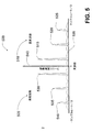
ここで、発明の実施形態が示されている図1−6を参照して、これ以降に本発明の例示的実施形態をより十分に記載する。図1は、本発明の一実施形態に従った、マイクロ波センサーの例示的設置の切開図とアンテナに戻される干渉するクラッター信号の表現である。図2aは、本発明の一実施形態に従った、関心のあるブレード(中央ブレード)がセンサーのアンテナに対して接近速度を持って動く、マイクロ波センサーによって測定されているブレードの表現である。図2bは、本発明の一実施形態に従った、関心のあるブレード(中央ブレード)がセンサーのアンテナに対してゼロ速度点に置かれている、マイクロ波センサーによって測定されているブレードの表現である。図2cは、本発明の一実施形態に従った、関心のあるブレード(中央ブレード)がセンサーのアンテナに対して後退速度を持って動く、マイクロ波センサーによって測定されているブレードの表現である。図3は、本発明の一実施形態に従った、それがアンテナの傍を通過する時の単一のブレードについてのブレード速度対時間のグラフィック表現である。図4は、本発明の例示的実施形態に従った、ブレード先端測定のためのプロセスのフローチャート図である。図5は、本発明の一実施形態に従った、接近(正の)および後退(負の)周波数を示す受信コヒーレントマイクロ波センサーデータについてのFFT振幅出力である。図6は、本発明の一実施形態に従った、ブレードエリアを選択し、ブレード測定のためのゼロ速度点を選ぶための方法論を示す例示的グラフである。 Reference will now be made more fully to exemplary embodiments of the present invention with reference to FIGS. 1-6, in which embodiments of the invention are shown. FIG. 1 is a cut-away view of an exemplary installation of a microwave sensor and a representation of an interfering clutter signal returned to an antenna, in accordance with one embodiment of the present invention. FIG. 2a is a representation of a blade being measured by a microwave sensor in which the blade of interest (center blade) moves with an approach velocity relative to the sensor antenna, in accordance with one embodiment of the present invention. FIG. 2b is a representation of a blade being measured by a microwave sensor in which the blade of interest (center blade) is placed at a zero velocity point relative to the sensor antenna, according to one embodiment of the invention. is there. FIG. 2c is a representation of a blade being measured by a microwave sensor in which the blade of interest (central blade) moves with a retracting speed relative to the sensor antenna, in accordance with one embodiment of the present invention. FIG. 3 is a graphical representation of blade speed versus time for a single blade as it passes by the antenna, according to one embodiment of the present invention. FIG. 4 is a flowchart diagram of a process for blade tip measurement, in accordance with an exemplary embodiment of the present invention. FIG. 5 is an FFT amplitude output for received coherent microwave sensor data showing approach (positive) and retract (negative) frequencies according to one embodiment of the present invention. FIG. 6 is an exemplary graph illustrating a methodology for selecting a blade area and selecting a zero velocity point for blade measurement, according to one embodiment of the present invention.
この発明は、多くの異なる形で実施することができ、ここで説明する実施形態に限定されるとは理解されるべきではない。むしろ、この開示が行届いていて完全であり、当業者に発明の範囲を十分に伝えるように、これらの実施形態は提供されている。しかも、ここで与えられる全ての代表的な「例」は、非限定的で本発明の例示的実施形態によってサポートされる他のものの中にあることが意図されている。 The present invention can be implemented in many different forms and should not be construed as limited to the embodiments set forth herein. Rather, these embodiments are provided so that this disclosure will be thorough and complete, and will fully convey the scope of the invention to those skilled in the art. Moreover, all representative “examples” given herein are intended to be among others that are non-limiting and supported by exemplary embodiments of the present invention.
図1は、筐体内で回転している、ブレード121のような、関心のある特定のブレードを測定するための、タービンエンジン115の筐体内に設置された、例示的マイクロ波アンテナ105を示す。ブレード121は、それのどちらかの側にブレード120とブレード122を有する。アンテナ105は、同軸ケーブルまたは導波管110を介してセンサーエレクトロニクス140に接続されている。アンテナ105は、典型的には少なくとも600°Fの温度にある、タービンエンジン115の動作環境内で生き残ることができるアンテナからなり、ブレードによって反射されることになるマイクロ波信号を送信する。その好ましい実施形態では、アンテナは、インコネルのような高温合金から作られた金属ハウジングをもったセラミック基板上に作られたマイクロストリップパッチアンテナである。アンテナ105とセンサーエレクトロニクス140の組合せは、典型的にはマイクロ波センサーと呼ばれる。
FIG. 1 shows an
例示的実施形態のために、センサーエレクトロニクス140は、マイクロ波トランシーバー145、信号調整およびアナログ−ディジタル変換器150、信号プロセッサ155という3つの主なサブコンポーネントからなる。マイクロ波トランシーバー145は、タービンエンジンの筐体内での送信のためのアンテナへマイクロ波エネルギーを送信し、回転するブレードから反射されて返るエネルギーを受信する。好ましい実施形態では、トランシーバーの受信機コンポーネントは、標準的ゼロ−IFホモダイン構成として実装される。スーパーホモダイン、パルスドップラー、またはディジタルI/Q受信機のような他の種類の受信機が、ここで議論するブレード測定のために使われても良い。受信機は、受信信号の振幅と位相の両方を測定することが可能であり、つまり受信機はコヒーレントデザインを特徴として持つ。好ましいゼロ−IFホモダイン構成では、同相チャネルと直角位相チャネルという2つのチャネルが、受信機からのベースバンド出力として利用可能である。
For the exemplary embodiment,
信号調整およびアナログ−ディジタル変換器モジュール150は典型的には、アナログ−ディジタル変換ステージの前にノイズを除去するローパスフィルタリングと、アナログ−ディジタル変換器のダイナミックレンジを最適化する増幅およびDCオフセット調節からなる。好ましい実施形態では、ローパスフィルタのための典型的なローパスカットオフ周波数は、数MHzでエンジンの最大ブレード先端速度によって50MHzまでに設定される。信号調整機能は、トランシーバー145によって出力されるアナログの同相および直角位相チャネル信号を処理する。これを受けて、アナログ−ディジタル変換器は、ローパスカットオフ周波数の少なくとも2倍の速度でこれらの信号をディジタル形式に変換する。これは、測定システム全体内で熱ノイズが最小化されることを確かなものとする。ディジタル信号は、信号プロセッサ155によって処理される。信号プロセッサ155は、PowerPC405プロセッサのようなマイクロプロセッサ、またはTexas Instrument TMS320c6414プロセッサのようなディジタル信号プロセッサ(DSP)によって実装することができる。一旦ディジタル信号が処理されて測定が行われたら、ブレード情報は出力表示または外部データ収集装置160に送られる。データは、RS−232、MODBUS、TCP/IPまたはその他の同様のディジタル通信プロトコルを介してディジタル形態でデータ収集装置160に出力されても良い。代替的に、データは、他のシステムによる記録のための0−20mAまたは電圧出力のようなアナログ信号として出力することができる。
The signal conditioning and analog-to-
図1はまた、アンテナ105から放射されるマイクロ波エネルギー125が、望ましいブレード先端からではなく、ブレード121の側面からはね返る条件を描いている。このシナリオでは、送信エネルギー125はブレード121の側面に当って反射135に結果としてなり、これはそれを受けて反射130がアンテナ105まで戻る前にブレード122に当る。ブレード先端ではなくブレード側面からの信号反射を表す反射をアンテナ105が受信するとき、一次測定で干渉を引き起こすことができる。ガスタービンエンジンの動作環境のための代表的な測定技術は、ここに引用によって完全に組み込まれる米国特許第6,489,917号に開示されている。
FIG. 1 also depicts a condition where the
図2aは、関心のあるブレードがセンサーのアンテナに向けて正の速度を持っている条件における、マイクロ波センサーによって測定されているブレードの表現である。ブレード121は測定されるべきブレードであり、ブレード122はアンテナ105を丁度通過したところで、ブレード120は測定されるべき次のブレードである。図2aのシナリオでは、関心のあるブレードであるブレード121はアンテナ105に接近している。ブレード121はアンテナに向けて正の速度を有し、一方ブレード122はそれが既にアンテナ105の傍を通過したので負の速度を有する。アンテナ105のボアサイトはブレード121と122の間にあるので、アンテナによって受信される反射エネルギーのほとんどは、これら2つのブレードの側面から導き出される。
FIG. 2a is a representation of a blade being measured by a microwave sensor in a condition where the blade of interest has a positive velocity towards the sensor antenna.
図2bは、関心のあるブレードがセンサーのアンテナに対してゼロ速度を持っている、マイクロ波センサーによって測定されているブレードの表現である。ブレード122はそれがアンテナ105から更に離れるように動いているので負の速度を有し、ブレード120は正の速度を有する。アンテナ105に戻る反射エネルギーのほとんどは、ブレード121のブレード先端からのものである。ブレード121はアンテナ105の丁度下に置かれているので、ブレードはゼロ速度を有する--それはアンテナに向かってもアンテナから離れるようにも動いていない。
FIG. 2b is a representation of a blade being measured by a microwave sensor, where the blade of interest has a zero velocity relative to the sensor antenna.
図2cは、関心のあるブレードがセンサーのアンテナに対して負の速度を持っている、マイクロ波センサーによって測定されているブレードの表現である。ブレード122はそれがアンテナ105から更に離れるように動いているので負の速度を有し、ブレード120は正の速度を有する。このシーケンスの回転しているブレードについては、しかしながら、ブレード120はここではアンテナ105から離れるように動いており、負の速度を有する。
FIG. 2c is a representation of a blade being measured by a microwave sensor, where the blade of interest has a negative velocity relative to the sensor antenna.
図3は、マイクロ波センサーのアンテナに対するブレード速度のグラフィック表現である。グラフ300は、時間をx−軸上に、速度をy−軸上に表す。正の速度はアンテナ105に接近しているブレードによって表される一方、負の速度はアンテナから離れていっているブレードによって表される。実際の速度は、半径方向速度にブレードとアンテナ105の間の角度のコサインを掛けることによって計算することができる。グラフ300に示されるように、アンテナ105に接近している間ブレードはその最大正速度305からスタートする。ブレードがアンテナ105の位置に近づくにつれて、ゼロ速度315に達する点まで速度は減少する。ブレードがアンテナ105から離れていき始めるにつれて、速度は負になり、最終的に最大負速度310に達する。
FIG. 3 is a graphic representation of the blade speed for the microwave sensor antenna. The
図4は、ブレード先端測定のための例示的プロセス400を示す論理的フローチャート図である。一般的に、プロセス400は、信号ピークを検出し、クラッターのような無関係な信号をフィルタし、関心のあるブレードのどちらかの側の各ブレードによって作り出された信号アーチファクトの除去をサポートする速度成分を同定することができる。プロセス400は、信号プロセッサ155上で動作するソフトウェアまたはファームウェアに実装することができる。
FIG. 4 is a logical flow chart diagram illustrating an
第一のステップ405のために、信号プロセッサ155は、モジュール150のアナログ−ディジタル変換器からコヒーレント同相および直角位相データを収集する。次のステップ410では、同相および直角位相信号成分について複素高速フーリエ変換(FFT)が計算される。標準的FFTアルゴリズムを高速化するのに必要とされるように、成分データを2乗まで0でパディングすることができることは、当業者には理解されるであろう。加えて、標準的FFT窓付け関数を使って副ローブ特性を削減することができる。複素FFTの出力は、正と負の周波数空間の両方に情報を生み出す。正の周波数はアンテナ105に接近しているブレードの周波数内容を表し、負の周波数はアンテナ105から離れていっているブレードの周波数内容を表す。
For the
ステップ415では、正と負の周波数成分が分離される。これは、FFTデータアレイの2つのコピーを作り、スペクトルの半分または他の半分に0を追加することによって達成することができる。例えば、もし正の周波数が逆にされたのであれば、スペクトルの負の周波数部分に相当するデータ値の全てが0にセットされ、その逆もしかりである。
In
ステップ420において、分離された正の周波数と負の周波数成分上で逆高速フーリエ変換(IFFT)が行われる。但し、もしステップ410中に窓付け関数が行われていれば、IFFT出力データについて窓は反転されるべきである。最終出力は、一つが接近しているブレードの内容を表し、一つが後退しているブレードの内容を表す、時間ドメインデータの2つの複素セットからなる。
In
ステップ425において、時間ドメインデータセットは振幅と位相の値に変換される。これは、当業者には周知の標準的直交−極変換を使って達成することができる。
In
ステップ430では、戻された信号強度(ステップ425からの振幅値)が予め規定された閾値と交差するエリアを同定することによって、ブレードが存在する時間ドメインデータのエリアを同定することができる。これを受けて、ブレードに相当するデータのセクションがステップ435に渡され、そこで正と負の位相が等しい位置によって測定点が同定される。ゼロ速度点は、2つのデータセットの間のベクトル減算を完了して、最小点を決定することによって選択することができる。実用においては、2つの位相が互いに交差する点を検出するのに位相データを使うことができる。この位相データに基づく技術は、追加のノイズ拒絶を達成できる。時間ドメインデータのインデックスは、接近位相が後退位相に等しいゼロ速度点によって規定される。
In
ゼロ速度インデックスはブレード処理モジュール(図示せず)に渡され、そこではステップ440で、当業者に知られているような従来のブレード処理アルゴリズムをブレードデータ上で実行することができる。典型的な処理は、信号位相からブレード先端間隙を、またはインデックスから到着時間を計算することと、システムのサンプルレートを知ることを含むであろう。
The zero speed index is passed to a blade processing module (not shown) where a conventional blade processing algorithm as known to those skilled in the art can be performed on the blade data at
図5は、プロセス400のステップ410で出力されるブレードデータのような、ブレードデータから導き出された代表的なフーリエ変換結果を示す。ブレードはセンサーのアンテナの前に来てそれから離れていくのでブレードの時間ドメインデータはしばしば中断された信号のように見えるため、スペクトルは多数の高調波を持つ傾向がある。正の周波数の高調波515、520、525と負の周波数の高調波530、535、540をグラフ500上に見ることができる。グラフ500の右手側の全ての正の周波数内容510はアンテナ105に接近しているブレードの時間ドメインデータからのものである。グラフ500の左手側の全ての負の周波数内容505はアンテナ105から後退しているブレードの時間ドメインデータからのものである。
FIG. 5 shows a representative Fourier transform result derived from blade data, such as the blade data output at
図6は、ブレードの存在を検出し(ステップ430)、ゼロ速度点を規定する(ステップ435)ための例示的方法論を示す。グラフ630はブレード振幅対時間のプロットを示す。ブレードがセンサーのアンテナを通過する毎に、振幅は最大値まで上昇し、それからブレードが離れていくにつれて再び減少し始める。但し、ブレードの複雑なジオメトリのだめに、最大振幅位置は必ずしもゼロ速度点ではない。
FIG. 6 illustrates an exemplary methodology for detecting the presence of a blade (step 430) and defining a zero velocity point (step 435).
ブレード信号635の振幅が、点650において、予め規定された閾値と交差するとき、ブレードが存在する。ブレード信号の振幅が、点655において、閾値より下に落ちるとき、ブレードは存在しないと考えられる。結果は、サーチ領域640またはブレード領域と呼ばれる、点650と655の間のブレードが存在する時間のエリアである。一旦サーチ領域が規定されると、同じ時間のエリアがブレード位相プロット605において検査される。ブレード位相プロット上で検査する時間のエリアは点660と665の間に記されている。このグラフは、接近している時間ドメイン信号620の位相と、後退している時間ドメイン信号615の位相という、2つの分かれたプロットを示す。接近している時間ドメイン信号は、+piから−pi(またはどのように位相が定義されているかによっては0から2pi)の間で位相ラップが起こるときを除いて、単調に減少する軌跡に沿っていく。後退している時間ドメイン信号は、+piから−pi(またはどのように位相が定義されているかによっては0から2pi)の間で位相ラップが起こるときを除いて、単調に増加する軌跡に沿っていく。各ブレードについて、接近および後退位相値が交差する単一の点620がある。これが、ブレード先端データのようなブレードデータ処理のために使われるゼロ速度点として規定される。図6のチャートに示される処理タスクをサポートするのに、当業者に知られている標準的交差検出方法を使うことができる。
A blade is present when the amplitude of the
まとめると、本発明の一側面は、タービンエンジンの筐体内で回転しているブレードのためのブレード測定を完了する方法を提供する。マイクロ波センサーに結合されたアンテナは、タービンエンジンの筐体内のアンテナを介してマイクロ波エネルギーを出力する。同相および直角位相データがマイクロ波センサーの受信機によって収集され、データはブレードと筐体によって反射されたマイクロ波エネルギーに少なくとも部分的に関連する。複素高速フーリエ変換(FFT)が同相(I)および直角位相(Q)データ上で行われて、正の周波数成分と負の周波数成分を生成する。正の周波数成分が負の周波数成分から分離される。これを受けて、逆FFTが正の周波数成分と負の周波数成分の各々の上で行われて、接近および後退速度成分に関連する複素時間ドメインデータを生成する。複素時間ドメインデータは振幅および位相値に変換され、振幅値は接近および後退振幅値からなり、位相値は接近および後退位相値からなる。アンテナに最も近いブレードの一つの位置に関連するブレード領域が、振幅値の所定の閾値との交差の対によって規定される。ゼロ点速度が、接近位相値の一つが後退位相値の一つと等しい点として規定される。ブレード領域の文脈では、ゼロ点速度はアンテナの直下のブレード、即ち関心のあるブレード、の位置を表す。 In summary, one aspect of the present invention provides a method for completing blade measurements for blades rotating within a turbine engine housing. An antenna coupled to the microwave sensor outputs microwave energy via an antenna in the turbine engine housing. In-phase and quadrature data are collected by the receiver of the microwave sensor, the data being at least partially related to the microwave energy reflected by the blade and the housing. A complex fast Fourier transform (FFT) is performed on the in-phase (I) and quadrature (Q) data to produce positive and negative frequency components. Positive frequency components are separated from negative frequency components. In response, an inverse FFT is performed on each of the positive frequency component and the negative frequency component to generate complex time domain data associated with the approach and reverse velocity components. The complex time domain data is converted into amplitude and phase values, the amplitude values are made up of approaching and backwards amplitude values, and the phase values are made up of approaching and backwards phase values. The blade area associated with the position of one of the blades closest to the antenna is defined by a pair of intersections of amplitude values with a predetermined threshold. Zero point velocity is defined as the point where one of the approach phase values is equal to one of the reverse phase values. In the context of the blade region, the zero point velocity represents the position of the blade directly below the antenna, ie the blade of interest.
関心のあるブレードのブレードデータは、ゼロ点速度をインデックスとして使って処理することができる。ブレードデータは、検出されたブレードピークの位相、振幅、時間を含む、同相および直角位相成分データから生成することができるパラメータによって表される。例えば、位相は距離またはブレード先端間隙に変換することができる。振幅は(同相および直角位相データの2乗の和の平方根として計算される)ブレードによって反射されて返るエネルギーの量に比例する。到着時間は、ピークが起こったサンプルを記し、サンプルレートを知って最後のピークとの間の時間を計算することによって計算することができる。 Blade data for the blade of interest can be processed using the zero point velocity as an index. Blade data is represented by parameters that can be generated from in-phase and quadrature component data, including phase, amplitude, and time of detected blade peaks. For example, the phase can be converted to distance or blade tip clearance. The amplitude is proportional to the amount of energy reflected back by the blade (calculated as the square root of the sum of the squares of the in-phase and quadrature data). The arrival time can be calculated by noting the sample where the peak occurred and knowing the sample rate and calculating the time between the last peak.
Claims (2)
前記タービンエンジンの前記筐体内のアンテナを介してマイクロ波エネルギーを送信するステップと、
前記ブレード及び前記筐体によって反射された前記マイクロ波エネルギーに関連する同相及び直角位相データを収集するステップと、
前記同相及び直角位相データ上で複素高速フーリエ変換(FFT)を行って、正の周波数成分及び負の周波数成分を生成するステップと、
前記負の周波数成分から前記正の周波数成分を分離するステップと、
前記正の周波数成分及び前記負の周波数成分の各々の上で逆FFTを行って、接近及び後退速度成分に関連する複素時間ドメインデータを生成するステップと、
前記複素時間ドメインデータを、接近及び後退振幅値を含む振幅値並びに接近及び後退位相値を含む位相値に変換するステップと、
前記振幅値と所定の閾値との各交差を同定して、前記アンテナに最も近いブレードの一つの位置に関連するブレード領域を規定するステップと、
前記ブレード領域について、前記アンテナの直下のブレードの位置を表すゼロ点速度を前記接近位相値の一つが前記後退位相値の一つと等しい点として同定するステップと、
前記ゼロ点速度をインデックスとして使ってブレードデータを処理するステップと
を含む方法。A method for completing a blade measurement of a rotating blade in a turbine engine housing, comprising:
Transmitting microwave energy through the housing of the antenna of the turbine engine,
A step of collecting in-phase and quadrature phase data associated with the microwave energy reflected by said blade and said housing,
A step of the on-phase and quadrature phase data by performing a complex Fast Fourier Transform (FFT), to produce a positive frequency component and a negative frequency component,
Separating said positive frequency component from the negative frequency components,
A step in which the positive frequency component and performing an inverse FFT on each of the negative frequency components, and generates a complex time-domain data associated with the approach and retraction velocity component,
Converting said complex time-domain data, the phase values including an amplitude value and contact proximal and receding phase values including approach and retraction amplitude value,
A step of defining said identified intersections between the amplitude value and a predetermined threshold value, the blade region associated with one position of the nearest blades to the antenna,
For the blade region, the steps of the zero point speed representing the position of the blade immediately below the antenna one of said approach phase value identified as point equal to one of the receding phase values,
Processing the blade data using the zero rate as an index
Including methods.
Applications Claiming Priority (2)
| Application Number | Priority Date | Filing Date | Title |
|---|---|---|---|
| US81010506P | 2006-06-01 | 2006-06-01 | |
| PCT/US2007/012920 WO2008036136A2 (en) | 2006-06-01 | 2007-06-01 | Peak detection and clutter reduction for a microwave sensor |
Publications (3)
| Publication Number | Publication Date |
|---|---|
| JP2009539110A JP2009539110A (en) | 2009-11-12 |
| JP2009539110A5 JP2009539110A5 (en) | 2010-07-01 |
| JP4553975B2 true JP4553975B2 (en) | 2010-09-29 |
Family
ID=39201022
Family Applications (1)
| Application Number | Title | Priority Date | Filing Date |
|---|---|---|---|
| JP2009513292A Expired - Fee Related JP4553975B2 (en) | 2006-06-01 | 2007-06-01 | Peak detection and clutter reduction for microwave sensors |
Country Status (6)
| Country | Link |
|---|---|
| US (1) | US7483800B2 (en) |
| EP (1) | EP2024604B1 (en) |
| JP (1) | JP4553975B2 (en) |
| CA (1) | CA2654057C (en) |
| ES (1) | ES2394114T3 (en) |
| WO (1) | WO2008036136A2 (en) |
Families Citing this family (20)
| Publication number | Priority date | Publication date | Assignee | Title |
|---|---|---|---|---|
| DE102006033461A1 (en) * | 2006-07-19 | 2008-01-31 | Siemens Ag | Radial gap measurement on turbines |
| DE102010003347B4 (en) | 2009-05-20 | 2021-08-05 | Robert Bosch Gmbh | Method and device for determining one or more speeds of a charging device, in particular for an internal combustion engine |
| US8624603B2 (en) | 2010-11-22 | 2014-01-07 | General Electric Company | Sensor assembly and methods of adjusting the operation of a sensor |
| US8593156B2 (en) | 2010-11-22 | 2013-11-26 | General Electric Company | Sensor assembly and microwave emitter for use in a sensor assembly |
| US8854052B2 (en) | 2010-11-22 | 2014-10-07 | General Electric Company | Sensor assembly and method of measuring the proximity of a machine component to a sensor |
| US8531191B2 (en) | 2010-11-22 | 2013-09-10 | General Electric Company | Sensor assembly and methods of measuring a proximity of a machine component to a sensor |
| US8482456B2 (en) | 2010-12-16 | 2013-07-09 | General Electric Company | Sensor assembly and method of measuring the proximity of a machine component to an emitter |
| CN103748473B (en) * | 2011-03-23 | 2016-06-29 | 梅吉特有限公司 | The measurement of the rotor with blade |
| US8742319B2 (en) | 2011-12-13 | 2014-06-03 | General Electric Company | Sensor and inspection system deploying an optical conduit |
| CN103808515B (en) * | 2012-11-12 | 2016-08-03 | 中航商用航空发动机有限责任公司 | Blade segregation apparatus and electromotor including experiment device |
| US9677868B2 (en) | 2013-10-09 | 2017-06-13 | Hamilton Sundstrand Corporation | Tip clearance measurement system |
| GB2528880A (en) * | 2014-08-01 | 2016-02-10 | Bae Systems Plc | Foreign object debris detection system and method |
| GB2528882A (en) | 2014-08-01 | 2016-02-10 | Bae Systems Plc | Turbine blade monitoring |
| GB2533626B (en) | 2014-12-23 | 2019-07-24 | Thales Holdings Uk Plc | Wind turbine rejection in non-scanning radar |
| DE102017109861A1 (en) | 2016-05-18 | 2017-11-23 | Infineon Technologies Ag | Methods and devices for speed and / or position detection |
| JP6747600B2 (en) * | 2017-08-31 | 2020-08-26 | 株式会社村田製作所 | Heart rate measuring device |
| US10705198B2 (en) * | 2018-03-27 | 2020-07-07 | Infineon Technologies Ag | System and method of monitoring an air flow using a millimeter-wave radar sensor |
| CN109141213B (en) * | 2018-09-08 | 2020-04-10 | 天津大学 | Blade tip clearance measurement method based on microwave frequency sweep |
| US11372097B2 (en) * | 2018-10-09 | 2022-06-28 | Metawave Corporation | Method and apparatus for phase unwrapping radar detections using optical flow |
| CN111006873B (en) * | 2019-12-05 | 2022-02-01 | 中国航发四川燃气涡轮研究院 | Method and device for acquiring peak value in blade tip clearance signal processing process |
Family Cites Families (12)
| Publication number | Priority date | Publication date | Assignee | Title |
|---|---|---|---|---|
| US4346383A (en) * | 1979-08-04 | 1982-08-24 | Emi Limited | Checking the location of moving parts in a machine |
| DE3044242A1 (en) * | 1979-12-11 | 1981-09-03 | Smiths Industries Ltd., London | DISPLAY SYSTEM FOR DISPLAYING THE DISTANCE OF THE BLADES OF A TURBINE TO A REFERENCE POINT |
| GB2322986B (en) * | 1987-10-28 | 1998-12-16 | Licentia Gmbh | Method of type classification of a target |
| JPH0494403A (en) * | 1990-08-03 | 1992-03-26 | Electric Power Res Inst Inc | Monitoring of resonance blade of turbine in operation |
| US5479826A (en) * | 1994-06-17 | 1996-01-02 | Westinghouse Electric Corporation | Microwave system for monitoring turbine blade vibration |
| US5818242A (en) * | 1996-05-08 | 1998-10-06 | United Technologies Corporation | Microwave recess distance and air-path clearance sensor |
| FR2807834B1 (en) * | 2000-04-13 | 2002-06-28 | Snecma Moteurs | NON-CONTACT MEASUREMENT METHOD OF VIBRATION OF A ROTATING BODY |
| US6489917B2 (en) * | 2000-11-30 | 2002-12-03 | Georgia Tech Research Corporation | Phase-based sensing system |
| GB2374670B (en) * | 2001-04-17 | 2004-11-10 | Rolls Royce Plc | Analysing vibration of rotating blades |
| US6717418B2 (en) * | 2001-11-16 | 2004-04-06 | General Electric Company | Method and apparatus for measuring turbine blade tip clearance |
| EP1617174A1 (en) * | 2004-07-12 | 2006-01-18 | Siemens Aktiengesellschaft | Radial clearance determination |
| JP2007218634A (en) * | 2006-02-14 | 2007-08-30 | Mitsubishi Electric Corp | Radar device |
-
2007
- 2007-06-01 ES ES07852378T patent/ES2394114T3/en active Active
- 2007-06-01 CA CA2654057A patent/CA2654057C/en not_active Expired - Fee Related
- 2007-06-01 JP JP2009513292A patent/JP4553975B2/en not_active Expired - Fee Related
- 2007-06-01 US US11/809,499 patent/US7483800B2/en not_active Expired - Fee Related
- 2007-06-01 WO PCT/US2007/012920 patent/WO2008036136A2/en active Application Filing
- 2007-06-01 EP EP07852378A patent/EP2024604B1/en active Active
Also Published As
| Publication number | Publication date |
|---|---|
| EP2024604B1 (en) | 2012-08-01 |
| WO2008036136A2 (en) | 2008-03-27 |
| WO2008036136A3 (en) | 2008-11-06 |
| CA2654057C (en) | 2013-02-12 |
| US7483800B2 (en) | 2009-01-27 |
| EP2024604A2 (en) | 2009-02-18 |
| CA2654057A1 (en) | 2008-03-27 |
| ES2394114T3 (en) | 2013-01-21 |
| JP2009539110A (en) | 2009-11-12 |
| EP2024604A4 (en) | 2011-06-29 |
| US20080195338A1 (en) | 2008-08-14 |
Similar Documents
| Publication | Publication Date | Title |
|---|---|---|
| JP4553975B2 (en) | Peak detection and clutter reduction for microwave sensors | |
| EP2275776B1 (en) | Method and apparatus for measuring turbine blade tip clearance | |
| US9784827B2 (en) | Foreign object debris detection system and method | |
| CN107678003A (en) | Object detection method and device under a kind of ground wave radar sea clutter background | |
| GB2533626B (en) | Wind turbine rejection in non-scanning radar | |
| CN111024209B (en) | Line spectrum detection method suitable for vector hydrophone | |
| CN111610503B (en) | Linear frequency modulation signal parameter estimation method based on improved LVD | |
| Wang et al. | A method of velocity estimation using composite hyperbolic frequency-modulated signals in active sonar | |
| CN109884337B (en) | Method for detecting sea surface wind direction by using high-frequency ground wave radar | |
| CN109541579B (en) | Bezier model-based Hough transform Doppler through-wall radar positioning method | |
| Liu et al. | SCH: a speed measurement method of combined hyperbolic frequency modulation signals | |
| KR101527772B1 (en) | METHOD FOR DETECTING TARGET OF FMCW(frequency-modulated continuous wave) RADAR AND FMCW RADAR FOR DETECTING TARGET | |
| JP3773779B2 (en) | Radar signal processing device | |
| JP3561497B2 (en) | Doppler radar signal processor | |
| CN112014833A (en) | High-speed target time-frequency domain detection method | |
| CN113167856A (en) | Interference suppression method and signal restoration method | |
| CN116087956A (en) | Traffic radar speed measurement method and device, radar and readable storage medium | |
| JP2002303645A (en) | Frequency measuring apparatus, frequency measuring method and radar system | |
| Ahmad et al. | Selection of window for inter-pulse analysis of simple pulsed radar signal using the short time Fourier transform | |
| CN110927710A (en) | High-precision high-resolution radar sensor and radar echo signal processing method | |
| Deng et al. | A method of extracting underwater acoustic beaconing signal | |
| Li et al. | Research on algorithm of FMCW radar level gauge | |
| CN113253280B (en) | Distance and speed measuring method combining hyperbolic frequency modulation and linear frequency modulation | |
| JP2872026B2 (en) | Direction measurement device | |
| CN113702969B (en) | Micro Doppler signal parameter estimation method based on self-adaptive STFT method |
Legal Events
| Date | Code | Title | Description |
|---|---|---|---|
| A521 | Written amendment |
Free format text: JAPANESE INTERMEDIATE CODE: A523 Effective date: 20100511 |
|
| A621 | Written request for application examination |
Free format text: JAPANESE INTERMEDIATE CODE: A621 Effective date: 20100511 |
|
| A871 | Explanation of circumstances concerning accelerated examination |
Free format text: JAPANESE INTERMEDIATE CODE: A871 Effective date: 20100511 |
|
| A975 | Report on accelerated examination |
Free format text: JAPANESE INTERMEDIATE CODE: A971005 Effective date: 20100604 |
|
| TRDD | Decision of grant or rejection written | ||
| A01 | Written decision to grant a patent or to grant a registration (utility model) |
Free format text: JAPANESE INTERMEDIATE CODE: A01 Effective date: 20100615 |
|
| A01 | Written decision to grant a patent or to grant a registration (utility model) |
Free format text: JAPANESE INTERMEDIATE CODE: A01 |
|
| A61 | First payment of annual fees (during grant procedure) |
Free format text: JAPANESE INTERMEDIATE CODE: A61 Effective date: 20100713 |
|
| FPAY | Renewal fee payment (event date is renewal date of database) |
Free format text: PAYMENT UNTIL: 20130723 Year of fee payment: 3 |
|
| R150 | Certificate of patent or registration of utility model |
Ref document number: 4553975 Country of ref document: JP Free format text: JAPANESE INTERMEDIATE CODE: R150 Free format text: JAPANESE INTERMEDIATE CODE: R150 |
|
| R250 | Receipt of annual fees |
Free format text: JAPANESE INTERMEDIATE CODE: R250 |
|
| R250 | Receipt of annual fees |
Free format text: JAPANESE INTERMEDIATE CODE: R250 |
|
| R250 | Receipt of annual fees |
Free format text: JAPANESE INTERMEDIATE CODE: R250 |
|
| R250 | Receipt of annual fees |
Free format text: JAPANESE INTERMEDIATE CODE: R250 |
|
| R250 | Receipt of annual fees |
Free format text: JAPANESE INTERMEDIATE CODE: R250 |
|
| R250 | Receipt of annual fees |
Free format text: JAPANESE INTERMEDIATE CODE: R250 |
|
| R250 | Receipt of annual fees |
Free format text: JAPANESE INTERMEDIATE CODE: R250 |
|
| LAPS | Cancellation because of no payment of annual fees |