EP2024604B1 - Peak detection and clutter reduction for a microwave sensor - Google Patents
Peak detection and clutter reduction for a microwave sensor Download PDFInfo
- Publication number
- EP2024604B1 EP2024604B1 EP07852378A EP07852378A EP2024604B1 EP 2024604 B1 EP2024604 B1 EP 2024604B1 EP 07852378 A EP07852378 A EP 07852378A EP 07852378 A EP07852378 A EP 07852378A EP 2024604 B1 EP2024604 B1 EP 2024604B1
- Authority
- EP
- European Patent Office
- Prior art keywords
- blade
- antenna
- phase
- blades
- approaching
- Prior art date
- Legal status (The legal status is an assumption and is not a legal conclusion. Google has not performed a legal analysis and makes no representation as to the accuracy of the status listed.)
- Active
Links
Images


Classifications
-
- F—MECHANICAL ENGINEERING; LIGHTING; HEATING; WEAPONS; BLASTING
- F01—MACHINES OR ENGINES IN GENERAL; ENGINE PLANTS IN GENERAL; STEAM ENGINES
- F01D—NON-POSITIVE DISPLACEMENT MACHINES OR ENGINES, e.g. STEAM TURBINES
- F01D21/00—Shutting-down of machines or engines, e.g. in emergency; Regulating, controlling, or safety means not otherwise provided for
- F01D21/003—Arrangements for testing or measuring
-
- G—PHYSICS
- G01—MEASURING; TESTING
- G01S—RADIO DIRECTION-FINDING; RADIO NAVIGATION; DETERMINING DISTANCE OR VELOCITY BY USE OF RADIO WAVES; LOCATING OR PRESENCE-DETECTING BY USE OF THE REFLECTION OR RERADIATION OF RADIO WAVES; ANALOGOUS ARRANGEMENTS USING OTHER WAVES
- G01S13/00—Systems using the reflection or reradiation of radio waves, e.g. radar systems; Analogous systems using reflection or reradiation of waves whose nature or wavelength is irrelevant or unspecified
- G01S13/02—Systems using reflection of radio waves, e.g. primary radar systems; Analogous systems
- G01S13/50—Systems of measurement based on relative movement of target
- G01S13/505—Systems of measurement based on relative movement of target using Doppler effect for determining closest range to a target or corresponding time, e.g. miss-distance indicator
-
- G—PHYSICS
- G01—MEASURING; TESTING
- G01S—RADIO DIRECTION-FINDING; RADIO NAVIGATION; DETERMINING DISTANCE OR VELOCITY BY USE OF RADIO WAVES; LOCATING OR PRESENCE-DETECTING BY USE OF THE REFLECTION OR RERADIATION OF RADIO WAVES; ANALOGOUS ARRANGEMENTS USING OTHER WAVES
- G01S13/00—Systems using the reflection or reradiation of radio waves, e.g. radar systems; Analogous systems using reflection or reradiation of waves whose nature or wavelength is irrelevant or unspecified
- G01S13/88—Radar or analogous systems specially adapted for specific applications
-
- G—PHYSICS
- G01—MEASURING; TESTING
- G01S—RADIO DIRECTION-FINDING; RADIO NAVIGATION; DETERMINING DISTANCE OR VELOCITY BY USE OF RADIO WAVES; LOCATING OR PRESENCE-DETECTING BY USE OF THE REFLECTION OR RERADIATION OF RADIO WAVES; ANALOGOUS ARRANGEMENTS USING OTHER WAVES
- G01S7/00—Details of systems according to groups G01S13/00, G01S15/00, G01S17/00
- G01S7/02—Details of systems according to groups G01S13/00, G01S15/00, G01S17/00 of systems according to group G01S13/00
- G01S7/41—Details of systems according to groups G01S13/00, G01S15/00, G01S17/00 of systems according to group G01S13/00 using analysis of echo signal for target characterisation; Target signature; Target cross-section
- G01S7/415—Identification of targets based on measurements of movement associated with the target
-
- F—MECHANICAL ENGINEERING; LIGHTING; HEATING; WEAPONS; BLASTING
- F05—INDEXING SCHEMES RELATING TO ENGINES OR PUMPS IN VARIOUS SUBCLASSES OF CLASSES F01-F04
- F05D—INDEXING SCHEME FOR ASPECTS RELATING TO NON-POSITIVE-DISPLACEMENT MACHINES OR ENGINES, GAS-TURBINES OR JET-PROPULSION PLANTS
- F05D2250/00—Geometry
- F05D2250/20—Three-dimensional
Definitions
- the present invention relates to microwave sensors and more particularly to peak detection in microwave sensors for measuring turbine blades or similarly shaped objects.
- Microwave techniques are known for measuring certain physical parameters within a gas turbine engine, such as blade tip clearance, which is the distance between the end of the blade and the turbine casing.
- Gas turbine engines provide some of the hottest environments for temperature measurements. Gas path temperatures can exceed 1093°C (2000°F), which is beyond the melting points of most metals.
- Antennas are typically used to transmit and receive electromagnetic energy within ambient temperature environments and in connection with a variety of devices, such as mobile phones, radios, global positioning receivers, and radar systems.
- Microwave sensors can also include one or more antennas to support the propagation of microwave signals within the desired measurement environment of a gas turbine engine. As an electromagnetic wave, the microwave signal will typically diverge and cover a larger area as the energy propagates further away from the antenna.
- the beamwidth characteristic of an antenna is typically measured as the angle at which the transmitted power is 3 dB below the on axis, or boresight power.
- Antennas used with microwave sensors for gas turbine engine measurements can have beamwidths that are 90 degrees or larger.
- Turbine engines typically have various internal stages comprising a set of blades attached to a rotating disk.
- a microwave sensor can be mounted through a hole or attached to the inside of the engine case to enable the antenna to cast its beam onto the blades, which will be rotating by the antenna during engine operation.
- the blades rotate close to the position of the sensor within the casing, typically in the range of 2,54 to 25,4 mm (0.1 to 1 inch) separation between each blade and the sensor position.
- Microwave signals travel much further distances than 25,4 mm (1 inch), however, resulting in the transmission of microwave signals that travel past the blade tips to the edges of the blade or other parts of the engine. Therefore, the resulting signal received by the microwave sensor often contains reflections from other objects that are not the target of interest, commonly referred to as clutter.
- Conventional techniques for removing clutter include (i) range gating or (ii) modeling clutter statistics and applying subtraction techniques to remove the influence of the interfering signal.
- the clutter is close to the target of interest, a few inches away or less.
- the bandwidth for range gating would be several GHz or more, which is impractical due to cost and difficulties in antenna design.
- Clutter subtraction techniques are insufficient for typical turbine engine measurements because the measurement of turbine blades using a microwave sensor require phase accuracies of less than one degree.
- Current clutter removal techniques are not capable of addressing this phase accuracy requirement. Therefore, another method of removing clutter from microwave sensor measurements is desirable for the operating environment of a gas turbine engine.
- the output waveforms for a typical microwave sensor used for blade measurements of a gas turbine engine have complex features as a result of microwave signal interaction with a complex turbine blade geometry.
- the identification of a single point on an output waveform for tip clearance or time of arrival measurements can be difficult as a result of the complex signal features.
- Typical peak detection methods, such as a polynomial curve fit, are too computationally intensive for the measurement of blades in real-time. Methods for finding a single point on the blade with the highest return signal can present variable results as the blade twists and changes dimensionally during normal operation. Nevertheless, a well defined, repeatable point for the engine blade is desirable for most blade tip measurements applications.
- the present invention provides an effective methodology for reducing the influence of clutter arising from a complex signal environment representative of the use of a microwave sensor with a gas turbine engine while achieving the accurate detection of peak signals for blade measurements obtained by the microwave sensor.
- a coherent signal is output by a microwave sensor attached to an antenna located within a gas turbine engine or other similar machine.
- the gas turbine engine include one or more stages of rotating blades within a confined operating environment formed by the casing of the engine.
- the antenna is typically placed in close proximity to the blade tip, often with a clearance of no more than 0.1 inch to I inch.
- the coherent microwave signal is converted to digital format and a complex Fast Fourier Transform (FFT) is performed on the digitized signal.
- FFT Fast Fourier Transform
- the output of the FFT calculation is then divided into components comprising velocities representing the movement of blades toward the antenna and velocities representing the movement of blades away from the antenna.
- FFT Fast Fourier Transform
- IFFT inverse Fast Fourier Transform
- the complex time domain signals are converted into magnitude and phase components associated with the approaching and receding velocities.
- the magnitude components represent the amount of reflected energy received by the sensor's antenna and the phase components represent the distance to the reflecting objects.
- the signal strength of the magnitude components is compared to a pre-defined threshold to detect when a blade is passing underneath the antenna of the microwave sensor.
- the phase components associated with the approaching and receding velocities are compared to determine a point where the two values are equal. This point is considered the zero velocity point -- the point where, from an electromagnetic perspective, the blade is directly underneath the antenna. At the zero velocity point, the phase measurement is noted for use as an index for the processing of blade data. All measurements for the blade can be taken at the appropriate data index for either the velocity filtered data or the original coherent data. This process can be repeated for the next blade in a rotation of blades for the turbine engine.
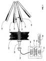
- FIG. 1 is the cut-away view of an exemplary installation of a microwave sensor and a representation of interfering clutter signals returned to the antenna in accordance with one embodiment of the present invention.
- FIG. 2a is a representation of a blade being measured by a microwave sensor, where the blade of interest (the center blade) moves with an approaching velocity with respect to the sensor's antenna in accordance with one embodiment of the present invention.
- FIG. 2b is a representation of a blade being measured by a microwave sensor, where the blade of interest (the center blade) is positioned at the zero velocity point with respect to the sensor's antenna in accordance with one embodiment of the present invention.
- FIG. 1 is the cut-away view of an exemplary installation of a microwave sensor and a representation of interfering clutter signals returned to the antenna in accordance with one embodiment of the present invention.
- FIG. 2a is a representation of a blade being measured by a microwave sensor, where the blade of interest (the center blade) moves with an approaching velocity with respect to the sensor's antenna in accordance with
- FIG. 2c is a representation of a blade being measured by a microwave sensor, where the blade of interest (the center blade) moves with a receding velocity with respect to the sensor's antenna in accordance with one embodiment of the present invention.
- FIG. 3 is a graphic representation of blade velocity versus time for a single blade as it passes by the sensor's antenna in accordance with one embodiment of the present invention.
- FIG. 4 is a flow chart diagram of a process for blade measurement in accordance with an exemplary embodiment of the present invention.
- FIG. 5 is an FFT magnitude output for received coherent microwave sensor data showing the approaching (positive) and receding (negative) frequencies in accordance with one embodiment of the present invention.
- FIG. 6 is an exemplary graph showing a methodology for selecting blade areas and choosing the zero velocity point for blade measurements in accordance with one embodiment of the present invention.
- FIG. 1 shows an exemplary microwave antenna 105 installed within the casing of a turbine engine 115 for measuring a particular blade of interest, such as blade 121, rotating within the casing.
- Blade 121 has blade 120 and blade 122 on either side of it.
- the antenna 105 is connected to sensor electronics 140 via a coaxial cable or waveguide 110.
- the antenna 105 comprises an antenna that can survive within the operating environment of the turbine engine 115 , typically at a temperature of at least 310°C (600° F), and transmit microwave signals that would be reflected by the blades.
- the antenna is a microstrip patch antenna made on a ceramic substrate with a metal housing made of a high temperature alloy such as inconel.
- the combination of the antenna 105 and the sensor electronics 140 is typically referred to as a microwave sensor.
- the sensor electronics 140 comprises three major subcomponents, a microwave transceiver 145 , a signal conditioning and analog-to-digital converter 150 , and a signal processor 155 .
- the microwave transceiver 145 transmits microwave energy to the antenna for transmission within the casing of the turbine engine and receives energy reflected back from the rotating blades.
- the receiver component of the transceiver 145 is implemented as a standard zero-IF homodyne configuration. Other types of receivers, such as a super heterodyne, pulse Doppler or digital I/Q receiver, may be used for the blade measurements discussed herein.
- the receiver is capable of measuring both magnitude and phase of the received signal, i.e. , the receiver features a coherent design. In the preferred zero-IF homodyne configuration, two channels, an in-phase channel and a quadrature channel, are available as baseband outputs from the receiver.
- the signal conditioning and analog-to-digital converter module 150 typically comprises low pass filtering to remove noise before the analog to digital conversion stage and amplification and DC offset adjustment to optimize the dynamic range of the analog-to-digital converter.
- the typical low pass cutoff frequencies for the low pass filter are set at several MHz and up to 50 MHz depending on the maximum blade tip speed of the engine.
- the signal conditioning function processes the analog in-phase and quadrature channel signals output by the transceiver 145.
- the analog-to-digital converter converts these signals to a digital format at speed of at least twice the low pass cutoff frequency. This ensures that the thermal noise within the overall measurement system is minimized.
- the digitized signals are processed by a signal processor 155.
- the signal processor 155 can be implemented by a microprocessor, such as a PowerPC 405 processor, or a digital signal processor (DSP), such as a Texas Instrument TMS320c6414 processor.
- a microprocessor such as a PowerPC 405 processor, or a digital signal processor (DSP), such as a Texas Instrument TMS320c6414 processor.
- DSP digital signal processor
- the blade information is sent to an output display or an external data collection device 160.
- the data may be output to the data collection device 160 in digital form via RS-232, MODBUS, TCP/IP or other similar digital communications protocol.
- the data can be output as an analog signal such as a 0-20 mA or voltage output for recording by another system.
- the signal processor 155 collects coherent in-phase and quadrature data from the analog-to-digital converter of the module 150 .
- a complex Fast Fourier Transform (FFT) is calculated for the in-phase and quadrature signal components.
- FFT Fast Fourier Transform
- the component data can be zero-padded to a power of two as needed to speed-up the standard FFT algorithm.
- standard FFT windowing functions can be used to reduce side lobe characteristics.
- the output of the complex FFT yields information in both positive and negative frequency space. Positive frequencies represent the frequency content of blades approaching antenna 105 ; negative frequencies represent frequency content of blades moving away from antenna 105 .
- step 415 the positive and negative frequency components are separated. This can be accomplished by making two copies of the FFT data arrays and adding zeros to one-half of the spectrum or the other half. For example, if the positive frequencies are inversed, then all of the data values corresponding to the negative frequency portion of the spectrum would be set to zero and vice versa.
- an inverse Fast Fourier Transform is performed on the separated positive frequencies and negative frequency components. If a windowing function was performed during the step 410, however, then the window should be reversed for the IFFT output data.
- the final output comprises two complex sets of time domain data, one representing the approaching blade content and one representing the receding blade content.
- the time domain data sets are converted to magnitude and phase values. This can be accomplished by using a standard rectangular-to-polar conversion well known to those versed in the art.
- the areas of the time domain data where the blades are present can be identified by identifying the areas where the returned signal strength (the magnitude value from step 425) crosses a pre-defined threshold.
- the sections of data corresponding to blades are passed to step 435, where the measurement point is identified by the location where the positive and negative phases are equal.
- the zero velocity point can be selected by completing a vector subtraction between the two data sets and determining the minimum point.
- phase data can be used to detect the point where the two phases cross one another. This phase data-based technique can achieve additional noise rejection.
- the index of the time domain data is defined by the zero velocity point, where the approaching phase equals the receding phase.
- the zero velocity index is passed to a blade processing module (not shown) where, in step 440 , a conventional blade processing algorithm, as known to those versed in the art, can be run on the blade data.
- Typical processing would include calculating the blade tip clearance from the signal phase, or the time of arrival from the index and knowing the sample rate of the system.
- FIG. 5 shows a representative Fourier transform result derived from blade data, such as the blade data output in step 410 of the process 400 .
- blade data such as the blade data output in step 410 of the process 400 .
- the spectrum tends to have a large number of harmonics.
- Positive frequency harmonics 515 , 520 , and 525 and negative frequency harmonics 530 , 535 , and 540 can be seen on graph 500 .
- All positive frequency content 510 on the right hand side of graph 500 is from time domain data of blades approaching antenna 105 .
- All negative frequency content 505 on the left hand side of graph 500 is from time domain data of blades receding from antenna 105 .
- FIG. 6 shows an exemplary methodology for detecting the presence of blades (step 430 ) and defining the zero velocity point (step 435 ).
- Graph 630 shows a plot of the blade magnitude versus time. Each time a blade passes the sensor's antenna, the magnitude will rise to a maximum value and then start to decrease again as the blade moves away. Due to the complex geometry of the blade, however, the maximum amplitude location is not necessarily the zero velocity point.
- the approaching time domain signal follows a monotonically decreasing trajectory, except when phase wraps occur between +pi to -pi (or 0 to 2pi depending on how the phase is defined).
- the receding time domain signal follows a monotonically increasing trajectory, except when phase wraps occur between +pi to -pi (or 0 to 2pi depending on how the phase is defined).
- For each blade there is a single point 620 where the approaching and receding phase values cross. This is defined as the zero velocity point that is used for blade data processing, such as blade tip data.
- a standard crossing detection method known to one versed in the art can be used to support the processing tasks shown in the charts of FIG. 6 .
- the present invention provides a method for performing a blade measurement for rotating blades within a casing of a turbine engine.
- An antenna coupled to a microwave sensor outputs microwave energy via an antenna within the casing of the turbine engine.
- In-phase and quadrature data are collected by a receiver of the microwave sensor, the data associated with, at least in part, microwave energy reflected by the blades and the casing.
- a complex Fast Fourier Transform (FFT) is performed on the in-phase (I) and quadrature (Q) data to generate positive frequency components and negative frequency components.
- the positive frequency components are separated from the negative frequency components.
- an inverse FFT is performed on each of the positive frequency components and the negative frequency components to generate complex time domain data associated with approaching and receding velocity components.
- the complex time domain data is converted to magnitude and phase values, the magnitude values comprising approaching and receding magnitude values and the phase values comprising approaching and receding phase values.
- a blade region associated with a location for one of the blades proximate to the antenna is defined by a pair of crossings of the magnitude values with a predetermined threshold.
- a zero velocity point is identified as the point where one of the approaching phase values equals one of the receding phase values. In the context of the blade region, the zero velocity point represents a location of the blade directly beneath the antenna, i.e., the blade of interest.
- Blade data for the blade of interest can be processed by using the zero velocity point as an index.
- Blade data is represented by parameters that can be generated from in-phase and quadrature component data, including phase, magnitude, and time of the detected blade peak.
- phase can converted to distance or blade tip clearance.
- Magnitude is proportional to the amount of energy reflected back by the blade (calculated by the square root of the sum of squares of the in-phase and quadrature data).
- Time of arrival can be calculated by noting the sample where the peak occurred and calculating the time between the last peak knowing the sample rate.
Abstract
Description
- The present invention relates to microwave sensors and more particularly to peak detection in microwave sensors for measuring turbine blades or similarly shaped objects.
- Microwave techniques are known for measuring certain physical parameters within a gas turbine engine, such as blade tip clearance, which is the distance between the end of the blade and the turbine casing. Gas turbine engines provide some of the hottest environments for temperature measurements. Gas path temperatures can exceed 1093°C (2000°F), which is beyond the melting points of most metals.
- Antennas are typically used to transmit and receive electromagnetic energy within ambient temperature environments and in connection with a variety of devices, such as mobile phones, radios, global positioning receivers, and radar systems. Microwave sensors can also include one or more antennas to support the propagation of microwave signals within the desired measurement environment of a gas turbine engine. As an electromagnetic wave, the microwave signal will typically diverge and cover a larger area as the energy propagates further away from the antenna. The beamwidth characteristic of an antenna is typically measured as the angle at which the transmitted power is 3 dB below the on axis, or boresight power. Antennas used with microwave sensors for gas turbine engine measurements can have beamwidths that are 90 degrees or larger.
- Turbine engines typically have various internal stages comprising a set of blades attached to a rotating disk. A microwave sensor can be mounted through a hole or attached to the inside of the engine case to enable the antenna to cast its beam onto the blades, which will be rotating by the antenna during engine operation. The blades rotate close to the position of the sensor within the casing, typically in the range of 2,54 to 25,4 mm (0.1 to 1 inch) separation between each blade and the sensor position. For accurate measurements, such as blade tip clearance or time of arrival, it is desirable to receive energy only from the tip area of the blade. Microwave signals travel much further distances than 25,4 mm (1 inch), however, resulting in the transmission of microwave signals that travel past the blade tips to the edges of the blade or other parts of the engine. Therefore, the resulting signal received by the microwave sensor often contains reflections from other objects that are not the target of interest, commonly referred to as clutter.
- Conventional techniques for removing clutter include (i) range gating or (ii) modeling clutter statistics and applying subtraction techniques to remove the influence of the interfering signal. Often, the clutter is close to the target of interest, a few inches away or less. For example, for the typical turbine engine measurement scenario, the bandwidth for range gating would be several GHz or more, which is impractical due to cost and difficulties in antenna design. Clutter subtraction techniques are insufficient for typical turbine engine measurements because the measurement of turbine blades using a microwave sensor require phase accuracies of less than one degree. Current clutter removal techniques are not capable of addressing this phase accuracy requirement. Therefore, another method of removing clutter from microwave sensor measurements is desirable for the operating environment of a gas turbine engine.
- The output waveforms for a typical microwave sensor used for blade measurements of a gas turbine engine have complex features as a result of microwave signal interaction with a complex turbine blade geometry. The identification of a single point on an output waveform for tip clearance or time of arrival measurements can be difficult as a result of the complex signal features. Typical peak detection methods, such as a polynomial curve fit, are too computationally intensive for the measurement of blades in real-time. Methods for finding a single point on the blade with the highest return signal can present variable results as the blade twists and changes dimensionally during normal operation. Nevertheless, a well defined, repeatable point for the engine blade is desirable for most blade tip measurements applications.
-
US 4 346 383 discloses: - a method for completing a blade measurement for rotating blades within a casing of a turbine engine, comprising the steps of:
- transmitting microwave energy via an antenna within the casing of the turbine engine;
- collecting data associated with the microwave energy reflected by the blades and the casing;
- detecting the phase difference between the transmitted and the received signal;
- processing blade data using the phase difference.
- In view of the foregoing, there is a need in the art for adapting the use of a microwave sensor to achieve blade measurements that are based on a repeatable point for the blade tip by minimizing the influence of interfering clutter signals.
- The invention is indicated in claim 1. A preferred embodiment is indicated in
claim 2. - The present invention provides an effective methodology for reducing the influence of clutter arising from a complex signal environment representative of the use of a microwave sensor with a gas turbine engine while achieving the accurate detection of peak signals for blade measurements obtained by the microwave sensor.
- In connection with an innovative blade measurement process, a coherent signal is output by a microwave sensor attached to an antenna located within a gas turbine engine or other similar machine. The gas turbine engine include one or more stages of rotating blades within a confined operating environment formed by the casing of the engine. The antenna is typically placed in close proximity to the blade tip, often with a clearance of no more than 0.1 inch to I inch. The coherent microwave signal is converted to digital format and a complex Fast Fourier Transform (FFT) is performed on the digitized signal. The output of the FFT calculation is then divided into components comprising velocities representing the movement of blades toward the antenna and velocities representing the movement of blades away from the antenna. These individual components are processed by an inverse Fast Fourier Transform (IFFT) to convert the components from the frequency domain to the time domain. The resulting complex time domain signals represent approaching and receding velocity components.
- The complex time domain signals are converted into magnitude and phase components associated with the approaching and receding velocities. The magnitude components represent the amount of reflected energy received by the sensor's antenna and the phase components represent the distance to the reflecting objects. To determine if a blade is present in the component data, the signal strength of the magnitude components is compared to a pre-defined threshold to detect when a blade is passing underneath the antenna of the microwave sensor.
- Upon detecting the blade region, the phase components associated with the approaching and receding velocities are compared to determine a point where the two values are equal. This point is considered the zero velocity point -- the point where, from an electromagnetic perspective, the blade is directly underneath the antenna. At the zero velocity point, the phase measurement is noted for use as an index for the processing of blade data. All measurements for the blade can be taken at the appropriate data index for either the velocity filtered data or the original coherent data. This process can be repeated for the next blade in a rotation of blades for the turbine engine.
- Other systems, methods, features, and advantages of the present invention will be or become apparent to one with skill in the art upon examination of the following drawings and detailed descriptions. It is intended that all such additional systems, methods, features, and advantages be included within this description, be within the scope of the present invention, and be protected by the accompanying claims.
- Many aspects of the invention can be better understood with reference to the following drawings. The components in the drawings are not necessarily to scale, emphasis instead being placed upon clearly illustrating the principles of exemplary embodiments of the present invention. Moreover, in the drawings, reference numerals designate corresponding parts throughout the several views.
-
FIG. 1 is the cut-away view of an exemplary installation of a microwave sensor and a representation of interfering clutter signals returned to the antenna in accordance with one embodiment of the present invention. -
FIG. 2a is a representation of a turbine engine blade being measured by a microwave sensor, where the blade of interest (the center blade) moves with an approaching velocity with respect to the sensor's antenna in accordance with one embodiment of the present invention. -
FIG. 2b is a representation of a turbine engine blade being measured by a microwave sensor, where the blade of interest (the center blade) is positioned at the zero velocity point with respect to the sensor's antenna in accordance with one embodiment of the present invention. -
FIG. 2c is a representation of a turbine engine blade being measured by a microwave sensor, where the blade of interest (the center blade) moves with a receding velocity with respect to the sensor's antenna in accordance with one embodiment of the present invention. -
FIG. 3 is a graphic representation of blade velocity versus time for a single blade as it passes by the antenna in accordance with one embodiment of the present invention. -
FIG. 4 is a flow chart diagram illustrating a process for blade tip measurement in accordance with an exemplary embodiment of the present invention. -
FIG. 5 is an illustration of a FFT magnitude output for received coherent microwave sensor data showing the approaching (positive) and receding (negative) frequencies in accordance with one embodiment of the present invention. -
FIG. 6 is an exemplary graph showing a methodology for selecting blade areas and choosing the zero velocity point for blade measurements in accordance with one embodiment of the present invention. - Exemplary embodiments of the present invention will now be described more fully hereinafter with reference to
FIGS. 1-6 .FIG. 1 is the cut-away view of an exemplary installation of a microwave sensor and a representation of interfering clutter signals returned to the antenna in accordance with one embodiment of the present invention.FIG. 2a is a representation of a blade being measured by a microwave sensor, where the blade of interest (the center blade) moves with an approaching velocity with respect to the sensor's antenna in accordance with one embodiment of the present invention.FIG. 2b is a representation of a blade being measured by a microwave sensor, where the blade of interest (the center blade) is positioned at the zero velocity point with respect to the sensor's antenna in accordance with one embodiment of the present invention.FIG. 2c is a representation of a blade being measured by a microwave sensor, where the blade of interest (the center blade) moves with a receding velocity with respect to the sensor's antenna in accordance with one embodiment of the present invention.FIG. 3 is a graphic representation of blade velocity versus time for a single blade as it passes by the sensor's antenna in accordance with one embodiment of the present invention.FIG. 4 is a flow chart diagram of a process for blade measurement in accordance with an exemplary embodiment of the present invention.FIG. 5 is an FFT magnitude output for received coherent microwave sensor data showing the approaching (positive) and receding (negative) frequencies in accordance with one embodiment of the present invention.FIG. 6 is an exemplary graph showing a methodology for selecting blade areas and choosing the zero velocity point for blade measurements in accordance with one embodiment of the present invention. - This invention can be embodied in many different forms and should not be construed as limited to the embodiments set forth herein; rather, these embodiments are provided so that this disclosure will be thorough and complete, and will fully convey the scope of the invention to those having ordinary skill in the art. Furthermore, all representative "examples" given herein are intended to be non-limiting, and among others, supported by exemplary embodiments of the present invention.
-
FIG. 1 shows anexemplary microwave antenna 105 installed within the casing of aturbine engine 115 for measuring a particular blade of interest, such asblade 121, rotating within the casing.Blade 121 hasblade 120 andblade 122 on either side of it. Theantenna 105 is connected tosensor electronics 140 via a coaxial cable orwaveguide 110. Theantenna 105 comprises an antenna that can survive within the operating environment of theturbine engine 115, typically at a temperature of at least 310°C (600° F), and transmit microwave signals that would be reflected by the blades. In its preferred embodiment, the antenna is a microstrip patch antenna made on a ceramic substrate with a metal housing made of a high temperature alloy such as inconel. The combination of theantenna 105 and thesensor electronics 140 is typically referred to as a microwave sensor. - For an exemplary embodiment, the
sensor electronics 140 comprises three major subcomponents, amicrowave transceiver 145, a signal conditioning and analog-to-digital converter 150, and asignal processor 155. Themicrowave transceiver 145 transmits microwave energy to the antenna for transmission within the casing of the turbine engine and receives energy reflected back from the rotating blades. In a preferred embodiment, the receiver component of thetransceiver 145 is implemented as a standard zero-IF homodyne configuration. Other types of receivers, such as a super heterodyne, pulse Doppler or digital I/Q receiver, may be used for the blade measurements discussed herein. The receiver is capable of measuring both magnitude and phase of the received signal, i.e., the receiver features a coherent design. In the preferred zero-IF homodyne configuration, two channels, an in-phase channel and a quadrature channel, are available as baseband outputs from the receiver. - The signal conditioning and analog-to-
digital converter module 150 typically comprises low pass filtering to remove noise before the analog to digital conversion stage and amplification and DC offset adjustment to optimize the dynamic range of the analog-to-digital converter. In a preferred embodiment, the typical low pass cutoff frequencies for the low pass filter are set at several MHz and up to 50 MHz depending on the maximum blade tip speed of the engine. The signal conditioning function processes the analog in-phase and quadrature channel signals output by thetransceiver 145. In turn, the analog-to-digital converter converts these signals to a digital format at speed of at least twice the low pass cutoff frequency. This ensures that the thermal noise within the overall measurement system is minimized. The digitized signals are processed by asignal processor 155. Thesignal processor 155 can be implemented by a microprocessor, such as aPowerPC 405 processor, or a digital signal processor (DSP), such as a Texas Instrument TMS320c6414 processor. Once the digitized signals have been processed and a measurement has been made, the blade information is sent to an output display or an externaldata collection device 160. The data may be output to thedata collection device 160 in digital form via RS-232, MODBUS, TCP/IP or other similar digital communications protocol. In the alternative, the data can be output as an analog signal such as a 0-20 mA or voltage output for recording by another system. -
FIG. 1 also illustrates a condition wheremicrowave energy 125 emanating from theantenna 105 bounces off of the side ofblade 121 rather than off of a desired blade tip. In this scenario, transmitenergy 125 hits the side ofblade 121 resulting inreflection 135 which, in turn, hitsblade 122 beforereflection 130 returns back to theantenna 105. Interference can be caused with the primary measurement when theantenna 105 receives reflections that represent signal reflections from a blade side rather than a blade tip. Representative measurement techniques for the operating environment of a gas turbine engine are disclosed inU.S. Patent No. 6,489,917 . -
FIG. 2a is a representation of a blade being measured by a microwave sensor in the condition where the blade of interest has a positive velocity towards the sensor's antenna.Blade 121 is the blade to be measured;blade 122 has just passed by theantenna 105; andblade 120 will be the next blade to be measured. In the scenario ofFIG. 2a , the blade of interest,blade 121 is approaching theantenna 105.Blade 121 will have a positive velocity towards the antenna, whileblade 122 will have a negative velocity because it has already passed by theantenna 105. Because the boresight ofantenna 105 is between theblades -
FIG. 2b is a representation of a blade being measured by a microwave sensor where the blade of interest has zero velocity with respect to the sensor's antenna.Blade 122 has a negative velocity because it is moving further away fromantenna 105 andblade 120 has a positive velocity. Most of the reflected energy back toantenna 105 is from the blade tip ofblade 121. Becauseblade 121 is positioned exactly under theantenna 105, the blade has a zero velocity - it is neither moving toward nor away from the antenna. -
FIG. 2c is a representation of a blade being measured by a microwave sensor where the blade of interest has negative velocity with respect to the sensor's antenna.Blade 122 has a negative velocity because it is moving further away fromantenna 105 andblade 120 has a positive velocity. For this sequence of rotating blades, however,blade 120 is now moving away from theantenna 105 and has a negative velocity. -
FIG. 3 is a graphical representation of blade velocity with respect to the antenna of a microwave sensor. Agraph 300 represents time on the x-axis and velocity on the y-axis. Positive velocity is represented by theblade approaching antenna 105 while negative velocity is represented by the blade moving away from the antenna. The actual velocity can be calculated by multiplying the radial velocity times the cosine of the angle between the blade and theantenna 105. As shown ingraph 300, the blade starts out at its maximumpositive velocity 305 while approaching theantenna 105. As the blade nears the location of theantenna 105, the velocity decreases to a point where it reaches a zerovelocity 315. As the blade starts to move away fromantenna 105, the velocity becomes negative and eventually reaches a maximumnegative velocity 310. -
FIG. 4 is a logical flow chart diagram showing anexemplary process 400 for blade tip measurements. In general, theprocess 400 can detect signal peaks, filter extraneous signals, such as clutter, and identify velocity components in support of the removal of signal artifacts created by each blade on either side of the blade of interest. Theprocess 400 can be implemented in software or firmware that operates on thesignal processor 155. - For the
first step 405, thesignal processor 155 collects coherent in-phase and quadrature data from the analog-to-digital converter of themodule 150. In thenext step 410, a complex Fast Fourier Transform (FFT) is calculated for the in-phase and quadrature signal components. It will be understood by those of skill in the art that the component data can be zero-padded to a power of two as needed to speed-up the standard FFT algorithm. In addition, standard FFT windowing functions can be used to reduce side lobe characteristics. The output of the complex FFT yields information in both positive and negative frequency space. Positive frequencies represent the frequency content ofblades approaching antenna 105; negative frequencies represent frequency content of blades moving away fromantenna 105. - In
step 415, the positive and negative frequency components are separated. This can be accomplished by making two copies of the FFT data arrays and adding zeros to one-half of the spectrum or the other half. For example, if the positive frequencies are inversed, then all of the data values corresponding to the negative frequency portion of the spectrum would be set to zero and vice versa. - At
step 420, an inverse Fast Fourier Transform (IFFT) is performed on the separated positive frequencies and negative frequency components. If a windowing function was performed during thestep 410, however, then the window should be reversed for the IFFT output data. The final output comprises two complex sets of time domain data, one representing the approaching blade content and one representing the receding blade content. - At
step 425, the time domain data sets are converted to magnitude and phase values. This can be accomplished by using a standard rectangular-to-polar conversion well known to those versed in the art. - In
step 430, the areas of the time domain data where the blades are present can be identified by identifying the areas where the returned signal strength (the magnitude value from step 425) crosses a pre-defined threshold. In turn, the sections of data corresponding to blades are passed to step 435, where the measurement point is identified by the location where the positive and negative phases are equal. The zero velocity point can be selected by completing a vector subtraction between the two data sets and determining the minimum point. In practice, phase data can be used to detect the point where the two phases cross one another. This phase data-based technique can achieve additional noise rejection. The index of the time domain data is defined by the zero velocity point, where the approaching phase equals the receding phase. - The zero velocity index is passed to a blade processing module (not shown) where, in
step 440, a conventional blade processing algorithm, as known to those versed in the art, can be run on the blade data. Typical processing would include calculating the blade tip clearance from the signal phase, or the time of arrival from the index and knowing the sample rate of the system. -
FIG. 5 shows a representative Fourier transform result derived from blade data, such as the blade data output instep 410 of theprocess 400. Because the time domain data for blades often looks like an interrupted signal as the blades come in front of and then away from the sensor's antenna, the spectrum tends to have a large number of harmonics.Positive frequency harmonics negative frequency harmonics graph 500. Allpositive frequency content 510 on the right hand side ofgraph 500 is from time domain data ofblades approaching antenna 105. Allnegative frequency content 505 on the left hand side ofgraph 500 is from time domain data of blades receding fromantenna 105. -
FIG. 6 shows an exemplary methodology for detecting the presence of blades (step 430) and defining the zero velocity point (step 435).Graph 630 shows a plot of the blade magnitude versus time. Each time a blade passes the sensor's antenna, the magnitude will rise to a maximum value and then start to decrease again as the blade moves away. Due to the complex geometry of the blade, however, the maximum amplitude location is not necessarily the zero velocity point. - When the magnitude of the
blade signal 635 crosses a pre-defined threshold, atpoint 650, a blade is present. When the magnitude of the blade signal drops below the threshold, atpoint 655, the blade is considered not to be present. The result is an area of time where the blade is present betweenpoints search region 640 or blade region. Once the search region is defined, the same area of time is examined in theblade phase plot 605. The area of time to examine on the blade phase plot is noted betweenpoints time domain signal 610 and the phase of the recedingtime domain signal 615. The approaching time domain signal follows a monotonically decreasing trajectory, except when phase wraps occur between +pi to -pi (or 0 to 2pi depending on how the phase is defined). The receding time domain signal follows a monotonically increasing trajectory, except when phase wraps occur between +pi to -pi (or 0 to 2pi depending on how the phase is defined). For each blade, there is asingle point 620 where the approaching and receding phase values cross. This is defined as the zero velocity point that is used for blade data processing, such as blade tip data. A standard crossing detection method known to one versed in the art can be used to support the processing tasks shown in the charts ofFIG. 6 . - In summary, the present invention provides a method for performing a blade measurement for rotating blades within a casing of a turbine engine. An antenna coupled to a microwave sensor outputs microwave energy via an antenna within the casing of the turbine engine. In-phase and quadrature data are collected by a receiver of the microwave sensor, the data associated with, at least in part, microwave energy reflected by the blades and the casing. A complex Fast Fourier Transform (FFT) is performed on the in-phase (I) and quadrature (Q) data to generate positive frequency components and negative frequency components. The positive frequency components are separated from the negative frequency components. In turn, an inverse FFT is performed on each of the positive frequency components and the negative frequency components to generate complex time domain data associated with approaching and receding velocity components. The complex time domain data is converted to magnitude and phase values, the magnitude values comprising approaching and receding magnitude values and the phase values comprising approaching and receding phase values. A blade region associated with a location for one of the blades proximate to the antenna is defined by a pair of crossings of the magnitude values with a predetermined threshold. A zero velocity point is identified as the point where one of the approaching phase values equals one of the receding phase values. In the context of the blade region, the zero velocity point represents a location of the blade directly beneath the antenna, i.e., the blade of interest.
- Blade data for the blade of interest can be processed by using the zero velocity point as an index. Blade data is represented by parameters that can be generated from in-phase and quadrature component data, including phase, magnitude, and time of the detected blade peak. For example, phase can converted to distance or blade tip clearance. Magnitude is proportional to the amount of energy reflected back by the blade (calculated by the square root of the sum of squares of the in-phase and quadrature data). Time of arrival can be calculated by noting the sample where the peak occurred and calculating the time between the last peak knowing the sample rate.
Claims (2)
- A method for performing a blade measurement for rotating blades (120, 121, 122) within a casing of a turbine engine (115) comprising the steps of:transmitting microwave energy via an antenna (105) within the casing of the turbine engine;colecting (405) in-phase and quadrature data associated with the microwave energy reflected by the blades and the casing;performing (410) a complex Fast Fourier Transform (FFT) on the in-phase and quadrature data to generate positive frequency components and negative frequency components;separating (415) the positive frequency components from the negative frequency components;performing (420) an inverse FFT on each of the positive frequency components and the negative frequency components to generate complex time domain data associated with approaching and receding velocity components;converting (425) the complex time domain data to magnitude and phase values, the magnitude values comprising approaching and receding magnitude values and the phase values comprising approaching and receding phase values;identifying (430) each crossing of the magnitude values with a predetermined threshold to define a blade region associated with a location for one of the blades proximate to the antenna;for the blade region, identifying (435) a zero velocity point as the point where one of the approaching phase values equals one of the receding phase values, the zero velocity point representing a location of the blade directly beneath the antenna; andprocessing (440) blade data using the zero velocity point as an index.
- The method of Claim 1 further comprising repeating each of the above-identified steps for another one of the blades.
Applications Claiming Priority (2)
| Application Number | Priority Date | Filing Date | Title |
|---|---|---|---|
| US81010506P | 2006-06-01 | 2006-06-01 | |
| PCT/US2007/012920 WO2008036136A2 (en) | 2006-06-01 | 2007-06-01 | Peak detection and clutter reduction for a microwave sensor |
Publications (3)
| Publication Number | Publication Date |
|---|---|
| EP2024604A2 EP2024604A2 (en) | 2009-02-18 |
| EP2024604A4 EP2024604A4 (en) | 2011-06-29 |
| EP2024604B1 true EP2024604B1 (en) | 2012-08-01 |
Family
ID=39201022
Family Applications (1)
| Application Number | Title | Priority Date | Filing Date |
|---|---|---|---|
| EP07852378A Active EP2024604B1 (en) | 2006-06-01 | 2007-06-01 | Peak detection and clutter reduction for a microwave sensor |
Country Status (6)
| Country | Link |
|---|---|
| US (1) | US7483800B2 (en) |
| EP (1) | EP2024604B1 (en) |
| JP (1) | JP4553975B2 (en) |
| CA (1) | CA2654057C (en) |
| ES (1) | ES2394114T3 (en) |
| WO (1) | WO2008036136A2 (en) |
Families Citing this family (20)
| Publication number | Priority date | Publication date | Assignee | Title |
|---|---|---|---|---|
| DE102006033461A1 (en) * | 2006-07-19 | 2008-01-31 | Siemens Ag | Radial gap measurement on turbines |
| DE102010003347B4 (en) | 2009-05-20 | 2021-08-05 | Robert Bosch Gmbh | Method and device for determining one or more speeds of a charging device, in particular for an internal combustion engine |
| US8531191B2 (en) | 2010-11-22 | 2013-09-10 | General Electric Company | Sensor assembly and methods of measuring a proximity of a machine component to a sensor |
| US8854052B2 (en) | 2010-11-22 | 2014-10-07 | General Electric Company | Sensor assembly and method of measuring the proximity of a machine component to a sensor |
| US8624603B2 (en) | 2010-11-22 | 2014-01-07 | General Electric Company | Sensor assembly and methods of adjusting the operation of a sensor |
| US8593156B2 (en) | 2010-11-22 | 2013-11-26 | General Electric Company | Sensor assembly and microwave emitter for use in a sensor assembly |
| US8482456B2 (en) | 2010-12-16 | 2013-07-09 | General Electric Company | Sensor assembly and method of measuring the proximity of a machine component to an emitter |
| US9267959B2 (en) * | 2011-03-23 | 2016-02-23 | Meggitt Sa | Measurement of bladed rotors |
| US8742319B2 (en) | 2011-12-13 | 2014-06-03 | General Electric Company | Sensor and inspection system deploying an optical conduit |
| CN103808515B (en) * | 2012-11-12 | 2016-08-03 | 中航商用航空发动机有限责任公司 | Blade segregation apparatus and electromotor including experiment device |
| US9677868B2 (en) | 2013-10-09 | 2017-06-13 | Hamilton Sundstrand Corporation | Tip clearance measurement system |
| GB2528882A (en) | 2014-08-01 | 2016-02-10 | Bae Systems Plc | Turbine blade monitoring |
| GB2528880A (en) | 2014-08-01 | 2016-02-10 | Bae Systems Plc | Foreign object debris detection system and method |
| GB2533626B (en) | 2014-12-23 | 2019-07-24 | Thales Holdings Uk Plc | Wind turbine rejection in non-scanning radar |
| DE102017109861A1 (en) | 2016-05-18 | 2017-11-23 | Infineon Technologies Ag | Methods and devices for speed and / or position detection |
| JP6747600B2 (en) * | 2017-08-31 | 2020-08-26 | 株式会社村田製作所 | Heart rate measuring device |
| US10705198B2 (en) * | 2018-03-27 | 2020-07-07 | Infineon Technologies Ag | System and method of monitoring an air flow using a millimeter-wave radar sensor |
| CN109141213B (en) * | 2018-09-08 | 2020-04-10 | 天津大学 | Blade tip clearance measurement method based on microwave frequency sweep |
| US11372097B2 (en) * | 2018-10-09 | 2022-06-28 | Metawave Corporation | Method and apparatus for phase unwrapping radar detections using optical flow |
| CN111006873B (en) * | 2019-12-05 | 2022-02-01 | 中国航发四川燃气涡轮研究院 | Method and device for acquiring peak value in blade tip clearance signal processing process |
Family Cites Families (12)
| Publication number | Priority date | Publication date | Assignee | Title |
|---|---|---|---|---|
| US4346383A (en) * | 1979-08-04 | 1982-08-24 | Emi Limited | Checking the location of moving parts in a machine |
| DE3044242A1 (en) * | 1979-12-11 | 1981-09-03 | Smiths Industries Ltd., London | DISPLAY SYSTEM FOR DISPLAYING THE DISTANCE OF THE BLADES OF A TURBINE TO A REFERENCE POINT |
| GB2322986B (en) * | 1987-10-28 | 1998-12-16 | Licentia Gmbh | Method of type classification of a target |
| JPH0494403A (en) * | 1990-08-03 | 1992-03-26 | Electric Power Res Inst Inc | Monitoring of resonance blade of turbine in operation |
| US5479826A (en) * | 1994-06-17 | 1996-01-02 | Westinghouse Electric Corporation | Microwave system for monitoring turbine blade vibration |
| US5818242A (en) * | 1996-05-08 | 1998-10-06 | United Technologies Corporation | Microwave recess distance and air-path clearance sensor |
| FR2807834B1 (en) * | 2000-04-13 | 2002-06-28 | Snecma Moteurs | NON-CONTACT MEASUREMENT METHOD OF VIBRATION OF A ROTATING BODY |
| US6489917B2 (en) * | 2000-11-30 | 2002-12-03 | Georgia Tech Research Corporation | Phase-based sensing system |
| GB2374670B (en) * | 2001-04-17 | 2004-11-10 | Rolls Royce Plc | Analysing vibration of rotating blades |
| US6717418B2 (en) * | 2001-11-16 | 2004-04-06 | General Electric Company | Method and apparatus for measuring turbine blade tip clearance |
| EP1617174A1 (en) * | 2004-07-12 | 2006-01-18 | Siemens Aktiengesellschaft | Radial clearance determination |
| JP2007218634A (en) * | 2006-02-14 | 2007-08-30 | Mitsubishi Electric Corp | Radar device |
-
2007
- 2007-06-01 JP JP2009513292A patent/JP4553975B2/en not_active Expired - Fee Related
- 2007-06-01 WO PCT/US2007/012920 patent/WO2008036136A2/en active Application Filing
- 2007-06-01 ES ES07852378T patent/ES2394114T3/en active Active
- 2007-06-01 EP EP07852378A patent/EP2024604B1/en active Active
- 2007-06-01 US US11/809,499 patent/US7483800B2/en not_active Expired - Fee Related
- 2007-06-01 CA CA2654057A patent/CA2654057C/en not_active Expired - Fee Related
Also Published As
| Publication number | Publication date |
|---|---|
| US7483800B2 (en) | 2009-01-27 |
| CA2654057A1 (en) | 2008-03-27 |
| WO2008036136A3 (en) | 2008-11-06 |
| ES2394114T3 (en) | 2013-01-21 |
| WO2008036136A2 (en) | 2008-03-27 |
| JP4553975B2 (en) | 2010-09-29 |
| JP2009539110A (en) | 2009-11-12 |
| CA2654057C (en) | 2013-02-12 |
| US20080195338A1 (en) | 2008-08-14 |
| EP2024604A4 (en) | 2011-06-29 |
| EP2024604A2 (en) | 2009-02-18 |
Similar Documents
| Publication | Publication Date | Title |
|---|---|---|
| EP2024604B1 (en) | Peak detection and clutter reduction for a microwave sensor | |
| US9784827B2 (en) | Foreign object debris detection system and method | |
| CN107678003A (en) | Object detection method and device under a kind of ground wave radar sea clutter background | |
| GB2533626B (en) | Wind turbine rejection in non-scanning radar | |
| CN112964204B (en) | Dynamic blade tip clearance measurement system and method based on microwave phase difference ranging | |
| CN111896926A (en) | Low-altitude target detection method and system based on strong clutter suppression | |
| CN111610503B (en) | Linear frequency modulation signal parameter estimation method based on improved LVD | |
| CN109975771A (en) | Wideband digital channel method based on three rank phase difference of signal | |
| Zeintl et al. | Evaluation of FMCW radar for vibration sensing in industrial environments | |
| JP2003329765A (en) | Apparatus and method for analyzing pulse reception | |
| KR101527772B1 (en) | METHOD FOR DETECTING TARGET OF FMCW(frequency-modulated continuous wave) RADAR AND FMCW RADAR FOR DETECTING TARGET | |
| JP3561497B2 (en) | Doppler radar signal processor | |
| JP3773779B2 (en) | Radar signal processing device | |
| JP2002303645A (en) | Frequency measuring apparatus, frequency measuring method and radar system | |
| Ahmad et al. | Selection of window for inter-pulse analysis of simple pulsed radar signal using the short time Fourier transform | |
| GB2322988A (en) | Damage assessment using radar | |
| CN110927710A (en) | High-precision high-resolution radar sensor and radar echo signal processing method | |
| CN113702969B (en) | Micro Doppler signal parameter estimation method based on self-adaptive STFT method | |
| Deng et al. | A method of extracting underwater acoustic beaconing signal | |
| Li et al. | Research on algorithm of FMCW radar level gauge | |
| Yingbo et al. | Implementation and Comparison of Signal Detection Methods in Radar Reconnaissance System | |
| KR100822348B1 (en) | Velocity estimation apparatus | |
| CN117452388A (en) | Method for detecting rotating target of distance-moving vortex electromagnetic wave radar | |
| Jian-Wen et al. | Detection of ships for OTHR based on AR-MUSIC algorithm | |
| CN115267721A (en) | Ground moving target radial velocity estimation method based on double-frequency SAR |
Legal Events
| Date | Code | Title | Description |
|---|---|---|---|
| PUAI | Public reference made under article 153(3) epc to a published international application that has entered the european phase |
Free format text: ORIGINAL CODE: 0009012 |
|
| 17P | Request for examination filed |
Effective date: 20081205 |
|
| AK | Designated contracting states |
Kind code of ref document: A2 Designated state(s): AT BE BG CH CY CZ DE DK EE ES FI FR GB GR HU IE IS IT LI LT LU LV MC MT NL PL PT RO SE SI SK TR |
|
| AX | Request for extension of the european patent |
Extension state: AL BA HR MK RS |
|
| RIN1 | Information on inventor provided before grant (corrected) |
Inventor name: GEISHEIMER, JONATHAN, L. Inventor name: HOLST, THOMAS |
|
| RIN1 | Information on inventor provided before grant (corrected) |
Inventor name: GEISHEIMER, JONATHAN, L. Inventor name: HOLST, THOMAS |
|
| A4 | Supplementary search report drawn up and despatched |
Effective date: 20110527 |
|
| RIC1 | Information provided on ipc code assigned before grant |
Ipc: F01B 25/00 20060101AFI20080425BHEP Ipc: G01S 7/41 20060101ALI20110523BHEP Ipc: G01S 13/50 20060101ALI20110523BHEP Ipc: G01S 13/88 20060101ALI20110523BHEP |
|
| GRAP | Despatch of communication of intention to grant a patent |
Free format text: ORIGINAL CODE: EPIDOSNIGR1 |
|
| GRAS | Grant fee paid |
Free format text: ORIGINAL CODE: EPIDOSNIGR3 |
|
| GRAA | (expected) grant |
Free format text: ORIGINAL CODE: 0009210 |
|
| AK | Designated contracting states |
Kind code of ref document: B1 Designated state(s): AT BE BG CH CY CZ DE DK EE ES FI FR GB GR HU IE IS IT LI LT LU LV MC MT NL PL PT RO SE SI SK TR |
|
| AX | Request for extension of the european patent |
Extension state: AL BA HR MK RS |
|
| REG | Reference to a national code |
Ref country code: GB Ref legal event code: FG4D |
|
| REG | Reference to a national code |
Ref country code: AT Ref legal event code: REF Ref document number: 568827 Country of ref document: AT Kind code of ref document: T Effective date: 20120815 Ref country code: CH Ref legal event code: EP |
|
| REG | Reference to a national code |
Ref country code: IE Ref legal event code: FG4D |
|
| REG | Reference to a national code |
Ref country code: DE Ref legal event code: R096 Ref document number: 602007024439 Country of ref document: DE Effective date: 20120927 |
|
| REG | Reference to a national code |
Ref country code: CH Ref legal event code: NV Representative=s name: ISLER AND PEDRAZZINI AG, CH |
|
| REG | Reference to a national code |
Ref country code: SE Ref legal event code: TRGR |
|
| REG | Reference to a national code |
Ref country code: NL Ref legal event code: T3 |
|
| REG | Reference to a national code |
Ref country code: ES Ref legal event code: FG2A Ref document number: 2394114 Country of ref document: ES Kind code of ref document: T3 Effective date: 20130121 |
|
| REG | Reference to a national code |
Ref country code: LT Ref legal event code: MG4D Effective date: 20120801 |
|
| PG25 | Lapsed in a contracting state [announced via postgrant information from national office to epo] |
Ref country code: IS Free format text: LAPSE BECAUSE OF FAILURE TO SUBMIT A TRANSLATION OF THE DESCRIPTION OR TO PAY THE FEE WITHIN THE PRESCRIBED TIME-LIMIT Effective date: 20121201 Ref country code: LT Free format text: LAPSE BECAUSE OF FAILURE TO SUBMIT A TRANSLATION OF THE DESCRIPTION OR TO PAY THE FEE WITHIN THE PRESCRIBED TIME-LIMIT Effective date: 20120801 Ref country code: CY Free format text: LAPSE BECAUSE OF FAILURE TO SUBMIT A TRANSLATION OF THE DESCRIPTION OR TO PAY THE FEE WITHIN THE PRESCRIBED TIME-LIMIT Effective date: 20120801 Ref country code: FI Free format text: LAPSE BECAUSE OF FAILURE TO SUBMIT A TRANSLATION OF THE DESCRIPTION OR TO PAY THE FEE WITHIN THE PRESCRIBED TIME-LIMIT Effective date: 20120801 |
|
| PG25 | Lapsed in a contracting state [announced via postgrant information from national office to epo] |
Ref country code: PT Free format text: LAPSE BECAUSE OF FAILURE TO SUBMIT A TRANSLATION OF THE DESCRIPTION OR TO PAY THE FEE WITHIN THE PRESCRIBED TIME-LIMIT Effective date: 20121203 Ref country code: LV Free format text: LAPSE BECAUSE OF FAILURE TO SUBMIT A TRANSLATION OF THE DESCRIPTION OR TO PAY THE FEE WITHIN THE PRESCRIBED TIME-LIMIT Effective date: 20120801 Ref country code: GR Free format text: LAPSE BECAUSE OF FAILURE TO SUBMIT A TRANSLATION OF THE DESCRIPTION OR TO PAY THE FEE WITHIN THE PRESCRIBED TIME-LIMIT Effective date: 20121102 Ref country code: BE Free format text: LAPSE BECAUSE OF FAILURE TO SUBMIT A TRANSLATION OF THE DESCRIPTION OR TO PAY THE FEE WITHIN THE PRESCRIBED TIME-LIMIT Effective date: 20120801 Ref country code: PL Free format text: LAPSE BECAUSE OF FAILURE TO SUBMIT A TRANSLATION OF THE DESCRIPTION OR TO PAY THE FEE WITHIN THE PRESCRIBED TIME-LIMIT Effective date: 20120801 Ref country code: SI Free format text: LAPSE BECAUSE OF FAILURE TO SUBMIT A TRANSLATION OF THE DESCRIPTION OR TO PAY THE FEE WITHIN THE PRESCRIBED TIME-LIMIT Effective date: 20120801 |
|
| PG25 | Lapsed in a contracting state [announced via postgrant information from national office to epo] |
Ref country code: EE Free format text: LAPSE BECAUSE OF FAILURE TO SUBMIT A TRANSLATION OF THE DESCRIPTION OR TO PAY THE FEE WITHIN THE PRESCRIBED TIME-LIMIT Effective date: 20120801 Ref country code: CZ Free format text: LAPSE BECAUSE OF FAILURE TO SUBMIT A TRANSLATION OF THE DESCRIPTION OR TO PAY THE FEE WITHIN THE PRESCRIBED TIME-LIMIT Effective date: 20120801 Ref country code: DK Free format text: LAPSE BECAUSE OF FAILURE TO SUBMIT A TRANSLATION OF THE DESCRIPTION OR TO PAY THE FEE WITHIN THE PRESCRIBED TIME-LIMIT Effective date: 20120801 Ref country code: RO Free format text: LAPSE BECAUSE OF FAILURE TO SUBMIT A TRANSLATION OF THE DESCRIPTION OR TO PAY THE FEE WITHIN THE PRESCRIBED TIME-LIMIT Effective date: 20120801 |
|
| PG25 | Lapsed in a contracting state [announced via postgrant information from national office to epo] |
Ref country code: SK Free format text: LAPSE BECAUSE OF FAILURE TO SUBMIT A TRANSLATION OF THE DESCRIPTION OR TO PAY THE FEE WITHIN THE PRESCRIBED TIME-LIMIT Effective date: 20120801 |
|
| PLBE | No opposition filed within time limit |
Free format text: ORIGINAL CODE: 0009261 |
|
| STAA | Information on the status of an ep patent application or granted ep patent |
Free format text: STATUS: NO OPPOSITION FILED WITHIN TIME LIMIT |
|
| 26N | No opposition filed |
Effective date: 20130503 |
|
| PG25 | Lapsed in a contracting state [announced via postgrant information from national office to epo] |
Ref country code: BG Free format text: LAPSE BECAUSE OF FAILURE TO SUBMIT A TRANSLATION OF THE DESCRIPTION OR TO PAY THE FEE WITHIN THE PRESCRIBED TIME-LIMIT Effective date: 20121101 |
|
| REG | Reference to a national code |
Ref country code: DE Ref legal event code: R097 Ref document number: 602007024439 Country of ref document: DE Effective date: 20130503 |
|
| PG25 | Lapsed in a contracting state [announced via postgrant information from national office to epo] |
Ref country code: MC Free format text: LAPSE BECAUSE OF FAILURE TO SUBMIT A TRANSLATION OF THE DESCRIPTION OR TO PAY THE FEE WITHIN THE PRESCRIBED TIME-LIMIT Effective date: 20120801 |
|
| REG | Reference to a national code |
Ref country code: IE Ref legal event code: MM4A |
|
| PG25 | Lapsed in a contracting state [announced via postgrant information from national office to epo] |
Ref country code: IE Free format text: LAPSE BECAUSE OF NON-PAYMENT OF DUE FEES Effective date: 20130601 |
|
| PG25 | Lapsed in a contracting state [announced via postgrant information from national office to epo] |
Ref country code: MT Free format text: LAPSE BECAUSE OF FAILURE TO SUBMIT A TRANSLATION OF THE DESCRIPTION OR TO PAY THE FEE WITHIN THE PRESCRIBED TIME-LIMIT Effective date: 20120801 |
|
| PG25 | Lapsed in a contracting state [announced via postgrant information from national office to epo] |
Ref country code: TR Free format text: LAPSE BECAUSE OF FAILURE TO SUBMIT A TRANSLATION OF THE DESCRIPTION OR TO PAY THE FEE WITHIN THE PRESCRIBED TIME-LIMIT Effective date: 20120801 |
|
| PG25 | Lapsed in a contracting state [announced via postgrant information from national office to epo] |
Ref country code: LU Free format text: LAPSE BECAUSE OF NON-PAYMENT OF DUE FEES Effective date: 20130601 Ref country code: HU Free format text: LAPSE BECAUSE OF FAILURE TO SUBMIT A TRANSLATION OF THE DESCRIPTION OR TO PAY THE FEE WITHIN THE PRESCRIBED TIME-LIMIT; INVALID AB INITIO Effective date: 20070601 |
|
| REG | Reference to a national code |
Ref country code: FR Ref legal event code: PLFP Year of fee payment: 10 |
|
| REG | Reference to a national code |
Ref country code: FR Ref legal event code: PLFP Year of fee payment: 11 |
|
| REG | Reference to a national code |
Ref country code: FR Ref legal event code: PLFP Year of fee payment: 12 |
|
| PGFP | Annual fee paid to national office [announced via postgrant information from national office to epo] |
Ref country code: NL Payment date: 20190515 Year of fee payment: 13 |
|
| PGFP | Annual fee paid to national office [announced via postgrant information from national office to epo] |
Ref country code: IT Payment date: 20190620 Year of fee payment: 13 Ref country code: DE Payment date: 20190521 Year of fee payment: 13 |
|
| PGFP | Annual fee paid to national office [announced via postgrant information from national office to epo] |
Ref country code: SE Payment date: 20190611 Year of fee payment: 13 Ref country code: FR Payment date: 20190429 Year of fee payment: 13 |
|
| PGFP | Annual fee paid to national office [announced via postgrant information from national office to epo] |
Ref country code: CH Payment date: 20190614 Year of fee payment: 13 |
|
| PGFP | Annual fee paid to national office [announced via postgrant information from national office to epo] |
Ref country code: GB Payment date: 20190529 Year of fee payment: 13 Ref country code: ES Payment date: 20190701 Year of fee payment: 13 Ref country code: AT Payment date: 20190528 Year of fee payment: 13 |
|
| REG | Reference to a national code |
Ref country code: DE Ref legal event code: R119 Ref document number: 602007024439 Country of ref document: DE |
|
| REG | Reference to a national code |
Ref country code: CH Ref legal event code: PL |
|
| REG | Reference to a national code |
Ref country code: NL Ref legal event code: MM Effective date: 20200701 |
|
| REG | Reference to a national code |
Ref country code: AT Ref legal event code: MM01 Ref document number: 568827 Country of ref document: AT Kind code of ref document: T Effective date: 20200601 |
|
| GBPC | Gb: european patent ceased through non-payment of renewal fee |
Effective date: 20200601 |
|
| PG25 | Lapsed in a contracting state [announced via postgrant information from national office to epo] |
Ref country code: FR Free format text: LAPSE BECAUSE OF NON-PAYMENT OF DUE FEES Effective date: 20200630 Ref country code: GB Free format text: LAPSE BECAUSE OF NON-PAYMENT OF DUE FEES Effective date: 20200601 Ref country code: NL Free format text: LAPSE BECAUSE OF NON-PAYMENT OF DUE FEES Effective date: 20200701 Ref country code: LI Free format text: LAPSE BECAUSE OF NON-PAYMENT OF DUE FEES Effective date: 20200630 Ref country code: CH Free format text: LAPSE BECAUSE OF NON-PAYMENT OF DUE FEES Effective date: 20200630 |
|
| PG25 | Lapsed in a contracting state [announced via postgrant information from national office to epo] |
Ref country code: DE Free format text: LAPSE BECAUSE OF NON-PAYMENT OF DUE FEES Effective date: 20210101 Ref country code: AT Free format text: LAPSE BECAUSE OF NON-PAYMENT OF DUE FEES Effective date: 20200601 Ref country code: SE Free format text: LAPSE BECAUSE OF NON-PAYMENT OF DUE FEES Effective date: 20200602 |
|
| REG | Reference to a national code |
Ref country code: SE Ref legal event code: EUG |
|
| REG | Reference to a national code |
Ref country code: ES Ref legal event code: FD2A Effective date: 20211026 |
|
| PG25 | Lapsed in a contracting state [announced via postgrant information from national office to epo] |
Ref country code: IT Free format text: LAPSE BECAUSE OF NON-PAYMENT OF DUE FEES Effective date: 20200601 |
|
| PG25 | Lapsed in a contracting state [announced via postgrant information from national office to epo] |
Ref country code: ES Free format text: LAPSE BECAUSE OF NON-PAYMENT OF DUE FEES Effective date: 20200602 |