JP4552995B2 - In-vehicle device and composite control system for vehicle - Google Patents
In-vehicle device and composite control system for vehicle Download PDFInfo
- Publication number
- JP4552995B2 JP4552995B2 JP2007271492A JP2007271492A JP4552995B2 JP 4552995 B2 JP4552995 B2 JP 4552995B2 JP 2007271492 A JP2007271492 A JP 2007271492A JP 2007271492 A JP2007271492 A JP 2007271492A JP 4552995 B2 JP4552995 B2 JP 4552995B2
- Authority
- JP
- Japan
- Prior art keywords
- vehicle
- control means
- turned
- output
- tpms
- Prior art date
- Legal status (The legal status is an assumption and is not a legal conclusion. Google has not performed a legal analysis and makes no representation as to the accuracy of the status listed.)
- Expired - Fee Related
Links
Images


Classifications
-
- B—PERFORMING OPERATIONS; TRANSPORTING
- B60—VEHICLES IN GENERAL
- B60C—VEHICLE TYRES; TYRE INFLATION; TYRE CHANGING; CONNECTING VALVES TO INFLATABLE ELASTIC BODIES IN GENERAL; DEVICES OR ARRANGEMENTS RELATED TO TYRES
- B60C23/00—Devices for measuring, signalling, controlling, or distributing tyre pressure or temperature, specially adapted for mounting on vehicles; Arrangement of tyre inflating devices on vehicles, e.g. of pumps or of tanks; Tyre cooling arrangements
- B60C23/02—Signalling devices actuated by tyre pressure
- B60C23/04—Signalling devices actuated by tyre pressure mounted on the wheel or tyre
- B60C23/0408—Signalling devices actuated by tyre pressure mounted on the wheel or tyre transmitting the signals by non-mechanical means from the wheel or tyre to a vehicle body mounted receiver
- B60C23/0422—Signalling devices actuated by tyre pressure mounted on the wheel or tyre transmitting the signals by non-mechanical means from the wheel or tyre to a vehicle body mounted receiver characterised by the type of signal transmission means
- B60C23/0433—Radio signals
- B60C23/0435—Vehicle body mounted circuits, e.g. transceiver or antenna fixed to central console, door, roof, mirror or fender
Description
本発明は、スマートエントリーシステムとしての機能とタイヤ空気圧監視システムとしての機能とを兼ね備えた車両用複合制御システムの車載装置と、この車載装置を備えてなる車両用複合制御システムに関する。 The present invention relates to an in-vehicle device of a combined control system for a vehicle that has both a function as a smart entry system and a function as a tire pressure monitoring system, and a combined control system for a vehicle including the in-vehicle device.
従来、自動車関連技術の分野においては、車両に搭載された車載装置が、他の機器と無線通信で情報伝送を行って、様々な制御を実行するシステムが種々実用化されている。
代表的な例を挙げれば、例えば、車両に搭載される車載装置と、車両の利用者が所持する携帯機とで構成されるスマートエントリーシステムを挙げることができる。この種のスマートエントリーシステムは、車載装置と携帯機との間で無線通信による認証が成立すれば、機械式キーでの操作を行わなくても、ドアのロック/アンロックやエンジン始動等の制御を実行できる仕組みになっている。
2. Description of the Related Art Conventionally, in the field of automobile-related technology, various systems have been put into practical use in which an in-vehicle device mounted on a vehicle performs information transmission by wireless communication with other devices and executes various controls.
If a typical example is given, the smart entry system comprised by the vehicle-mounted apparatus mounted in a vehicle and the portable device which the vehicle user possesses can be mentioned, for example. This type of smart entry system can be used to control door locking / unlocking and engine starting without the need to perform mechanical key operations if wireless communication authentication is established between the in-vehicle device and the portable device. It is a mechanism that can be executed.
また、他の例としては、例えば、車両に搭載される車載装置と、車両が備えるタイヤの空気圧や温度などを検出するタイヤセンサとで構成されるタイヤ空気圧監視システム(TPMS;Tire Pressure Monitoring System)を挙げることもできる。 As another example, for example, a tire pressure monitoring system (TPMS; Tire Pressure Monitoring System) configured by an in-vehicle device mounted on a vehicle and a tire sensor that detects the pressure and temperature of a tire included in the vehicle. Can also be mentioned.
このTPMSは、例えば、車両の各車輪に設けられたタイヤセンサがタイヤの空気圧を検出し、そのデータを電波で送信し、車載装置がタイヤセンサからの電波を受信することにより、タイヤの空気圧を監視する仕組みになっている。 In this TPMS, for example, a tire sensor provided on each wheel of the vehicle detects the tire air pressure, transmits the data by radio waves, and the in-vehicle device receives the radio waves from the tire sensors. It is a monitoring mechanism.
さらに、この種の無線通信を行うシステムにおいて、2種類の異なるシステムを統合した複合システムも既に提案されている(例えば、下記特許文献1参照)。下記特許文献1に記載された複合システムは、イグニッションオフの時はリモートキーレスエントリー(RKE;Remote Keyless Entry)システムとして機能し、イグニッションオンの時はTPMSとして機能するものである。 Further, in this type of wireless communication system, a composite system in which two different systems are integrated has already been proposed (see, for example, Patent Document 1 below). The composite system described in Patent Document 1 below functions as a remote keyless entry (RKE) system when the ignition is off, and functions as a TPMS when the ignition is on.
このような複合システムであれば、RKEシステムとTPMSとで、車載装置の構成の一部を兼用することができるので、スペース的に車両への搭載が容易になり、コスト的にも有利なシステムになるとされている。
ところで、上記特許文献1に記載の如く、RKEシステムとTPMSとの複合システムにおいて、イグニッションオンの時にRKEシステムとして機能しないことは、特に問題視されていない。 By the way, as described in Patent Document 1, it is not particularly regarded as a problem that the combined system of the RKE system and the TPMS does not function as the RKE system when the ignition is turned on.
しかし、スマートエントリーシステムとTPMSとの複合システムを考えた場合、RKEシステムとは異なり、イグニッションオンの時にスマートエントリーシステムとして機能しないことには問題がある。 However, when considering a combined system of a smart entry system and TPMS, unlike the RKE system, there is a problem in not functioning as a smart entry system when the ignition is on.
具体的には、スマートエントリーシステムの場合、イグニッションがオンかオフかを問わず、間欠的または所定のトリガに基づいて無線通信を継続することにより、携帯機が車両内に存在するのか車外へ持ち出されたのか、といったことを監視している。 Specifically, in the case of a smart entry system, regardless of whether the ignition is on or off, wireless communication is continued intermittently or based on a predetermined trigger, so that the portable device is taken out of the vehicle or not. It is monitored whether it was done.
そのため、上記特許文献1に記載の如く、単にイグニッションがオンになったことをもって、車載装置がTPMSとしての機能を制御することに専念してしまうと、携帯機との無線通信を適切に実施できず、携帯機の所在を確認することができなくなってしまう。 Therefore, as described in Patent Document 1, if the on-board device is devoted to controlling the function as the TPMS simply because the ignition is turned on, the wireless communication with the portable device can be appropriately performed. Therefore, it becomes impossible to confirm the location of the portable device.
したがって、単に上記特許文献1に記載の如き構成を採用するだけでは、スマートエントリーシステムとTPMSとの複合システムを構成することができず、特に、スマートエントリーシステムとしての機能を適切に制御できなくなるおそれがある、という問題があった。 Therefore, simply adopting the configuration as described in Patent Document 1 cannot form a composite system of the smart entry system and TPMS, and in particular, the function as the smart entry system may not be appropriately controlled. There was a problem that there was.
本発明は、上記問題を解決するためになされたものであり、その目的は、スマートエントリーシステムとしての機能およびTPMSとしての機能を、双方とも適切に制御可能な車両用複合制御システムの車載装置と、その車載装置を備えた車両用複合制御システムを提供することにある。 The present invention has been made to solve the above-described problems, and an object of the present invention is to provide an in-vehicle apparatus for a vehicle combined control system capable of appropriately controlling both a function as a smart entry system and a function as a TPMS. Another object of the present invention is to provide a composite control system for a vehicle including the in-vehicle device.
以下、本発明において採用した構成について説明する。
請求項1に記載の車載装置において、スマートエントリーシステム用の第1制御手段は、間欠的または所定のトリガに基づいて出力信号をオンにする。例えば、イグニッションオフの場合は、特にトリガが入らなくても所定時間が経過する毎に、間欠的に出力信号をオンにする。また、例えば、イグニッションオンの場合は、所定の照合実施条件が成立したことをトリガとして、トリガが入ったら出力信号をオンにする。
Hereinafter, the configuration employed in the present invention will be described.
The in-vehicle device according to claim 1, wherein the first control means for the smart entry system turns on the output signal intermittently or based on a predetermined trigger. For example, when the ignition is off, the output signal is intermittently turned on every time a predetermined time elapses even if the trigger is not activated. Further, for example, when the ignition is on, the trigger is that a predetermined collation execution condition is satisfied, and the output signal is turned on when the trigger is entered.
トリガとなる所定の照合実施条件は、既存のスマートエントリーシステムで採用されているものと同等の条件であればよく、例えば、イグニションオン中にドアが閉められた時には照合実施条件成立となり、車室内に携帯機があることを検出するため、照合を行う。なお、この場合、携帯機が車室内にない場合は携帯機持ち出し警報としてブザーを吹鳴させ、携帯機が持ち出された可能性があることを利用者に知らせるなどの対処がなされる点も、既存のスマートエントリーシステムと同様である。 The predetermined collation execution condition that serves as a trigger may be the same as that used in the existing smart entry system. For example, when the door is closed during ignition on, the collation execution condition is satisfied, and the vehicle interior In order to detect that there is a portable device, the verification is performed. In this case, if the portable device is not in the passenger compartment, a buzzer will be sounded as a portable device take-out alarm to inform the user that the portable device may have been taken out. It is the same as the smart entry system.
このように間欠的または所定のトリガに基づいて、第1制御手段からの出力信号がオンとなった場合に、受信手段は、車両のイグニッションスイッチがオンまたはオフいずれであっても、第1の動作モードに切り替えられる。 As described above, when the output signal from the first control unit is turned on intermittently or based on a predetermined trigger, the receiving unit can determine whether the first ignition switch of the vehicle is on or off. Switch to operating mode.
受信手段が、第1の動作モードに切り替えられた場合、携帯機から伝送されてくる情報を受信して、第1制御手段に対して出力する。その際、第1制御手段は、自身の出力する出力信号がオンの期間内に、受信手段から出力される「携帯機からの情報」を入力し、車両における各種制御の実行を許可する上で必要となる認証を行う。 When the receiving means is switched to the first operation mode, it receives information transmitted from the portable device and outputs it to the first control means. At this time, the first control means inputs “information from the portable device” output from the receiving means within a period in which the output signal output by the first control means is ON, and permits execution of various controls in the vehicle. Perform the necessary authentication.
つまり、スマートエントリーシステム用の第1制御手段は、車両のイグニッションスイッチがオンまたはオフいずれであっても、間欠的または所定のトリガに基づいて出力信号をオンにするたびに、この出力信号をイネーブル信号として「携帯機からの情報」を入力する動作を実行する。 That is, the first control means for the smart entry system enables the output signal every time the output signal is turned on intermittently or based on a predetermined trigger, regardless of whether the ignition switch of the vehicle is on or off. The operation of inputting “information from the portable device” as a signal is executed.
一方、受信手段は、車両のイグニッションスイッチがオン、且つ、第1制御手段からの出力信号がオフの場合に、第2の動作モードに切り替えられる。
受信手段が、第2の動作モードに切り替えられた場合、検出手段から伝送されてくる情報を受信して、第2制御手段に対して出力する。その際、第2制御手段は、車両のイグニッションスイッチがオン、且つ、第1制御手段からの出力信号がオフの期間内に、受信手段から出力される「検出手段からの情報」を入力し、検出手段から伝送されてくるタイヤの状態に関する情報を取得する。
On the other hand, the receiving means is switched to the second operation mode when the ignition switch of the vehicle is on and the output signal from the first control means is off.
When the receiving means is switched to the second operation mode, the information transmitted from the detecting means is received and output to the second control means. At that time, the second control means inputs “information from the detection means” output from the receiving means within a period in which the ignition switch of the vehicle is on and the output signal from the first control means is off, Information on the state of the tire transmitted from the detection means is acquired.
つまり、TPMS用の第2制御手段は、車両のイグニッションスイッチがオンであれば、第1制御手段が間欠的または所定のトリガに基づいて出力信号をオフにするたびに、「検出手段からの情報」を入力する動作を実行する。 That is, when the ignition switch of the vehicle is on, the second control means for TPMS is “information from the detecting means” every time the first control means turns off the output signal intermittently or based on a predetermined trigger. ”Is input.
以上のように構成された車載装置において、第2制御手段は、車両のイグニッションスイッチがオンであっても、第1制御手段が出力信号をオンとした時には「検出手段からの情報」を入力しなくなるので、この点で従来のTPMSが備える制御手段とは相違する。 In the in-vehicle apparatus configured as described above, the second control means inputs “information from the detection means” when the first control means turns on the output signal even when the ignition switch of the vehicle is on. This is different from the control means provided in the conventional TPMS.
ただし、第1制御手段が出力信号をオンとする期間は、「携帯機からの情報」を取得するのに要する期間であり、この期間は僅かである。しかも、TPMSが備える検出手段は、常にタイヤの状態を監視するとともに、きわめて頻繁に情報を送信し続けているので、第1制御手段が出力信号をオフにすれば、第2制御手段は、直ちに最新の情報を受信することができる。 However, the period during which the first control means turns on the output signal is a period required to acquire “information from the portable device”, and this period is short. Moreover, the detection means provided in the TPMS constantly monitors the tire condition and continues to transmit information very frequently. Therefore, if the first control means turns off the output signal, the second control means immediately The latest information can be received.
そのため、通常は、第2制御手段が情報を受信できない僅かな期間にタイヤの状態が急激に変化することは殆どなく、仮に変化したとしても、その変化が第2制御手段に伝達されるまでのタイムラグは、実用上、何ら問題を招かない程度である。 For this reason, normally, the tire state rarely changes abruptly during a short period during which the second control means cannot receive information, and even if it changes, the change will not be transmitted to the second control means. The time lag does not cause any problem in practical use.
したがって、上記のように構成された車載装置によれば、スマートエントリーシステムとしての機能およびTPMSとしての機能を、双方とも適切に制御することができる。
また、上記車載装置においては、間欠的または所定のトリガに基づいて出力信号をオンにするとともに、当該出力信号がオンの期間内に、受信手段から出力される携帯機からの情報を入力するように構成されている。このような第1制御手段と受信手段との間のインターフェースは、既存のスマートエントリーシステムにおいても、全く同等に構成されているものがある。
Therefore, according to the vehicle-mounted device configured as described above, both the function as the smart entry system and the function as the TPMS can be appropriately controlled.
In the in-vehicle device, the output signal is turned on intermittently or based on a predetermined trigger, and information from the portable device that is output from the receiving unit is input within a period in which the output signal is on. It is configured. Such an interface between the first control means and the receiving means may be configured in exactly the same manner in existing smart entry systems.
すなわち、既存のスマートエントリーシステムとして、制御手段と受信手段とを備え、制御手段が受信手段に対して間欠的または所定のトリガに基づいて電圧供給を行うとともに、当該電圧供給がなされる期間内に、受信手段から出力される携帯機からの情報を制御手段が入力するように構成されているものがある。 That is, as an existing smart entry system, a control means and a reception means are provided, and the control means supplies voltage to the reception means intermittently or based on a predetermined trigger, and within the period during which the voltage supply is made. In some cases, the control means inputs information from the portable device output from the receiving means.
このような構成において、制御手段の電圧供給端子からの出力を本発明でいう出力信号として扱えば、本発明の車載装置においては、既存のスマートエントリーシステムで採用されている制御手段を、そのまま上記第1制御手段として利用することが可能である。 In such a configuration, if the output from the voltage supply terminal of the control means is handled as an output signal in the present invention, the control means employed in the existing smart entry system is used as it is in the in-vehicle device of the present invention. It can be used as the first control means.
逆に言えば、上記第1制御手段は、既存のスマートエントリーシステムで採用されている機器と同等な機能を持つ機器と組み合わせることで、TPMSとしての構成を持たないスマートエントリーシステムを構成する際にも利用できる。 In other words, when the first control means is combined with a device having the same function as the device used in the existing smart entry system, when configuring a smart entry system that does not have a configuration as a TPMS. Can also be used.
このように、上記第1制御手段であれば、TPMSとしての構成を持たないスマートエントリーシステムとの共用化を図ることもできる。したがって、このような第1制御手段であれば、上記共用化に伴う量産効果によってコストダウンを図ることができ、TPMSとしての構成を持つシステム専用に設計された車載装置を備える場合に比べ、本発明の車載装置を安価に提供できるようになる。 Thus, if it is the said 1st control means, sharing with the smart entry system which does not have the structure as TPMS can also be aimed at. Therefore, with such a first control means, the cost can be reduced due to the mass production effect associated with the above-mentioned sharing, and compared with the case where an in-vehicle device designed exclusively for a system having a configuration as a TPMS is provided. The vehicle-mounted device of the invention can be provided at a low cost.
また、請求項2に記載の車載装置において、第2制御手段は、アクティブ状態またはスリープ状態になる。したがって、スリープ状態へ移行した際には、スリープ状態へ移行しないものに比べ、省電力化を図ることができる。
また、請求項3に記載の車載装置では、車両のイグニッションスイッチがオフ、且つ、第1制御手段からの出力信号がオフの期間内に、受信手段が作動停止状態になる。
したがって、車両のイグニッションスイッチがオフ、且つ、第1制御手段からの出力信号がオフの期間にも、受信手段が作動し続けるものに比べ、省電力化を図ることができる。
In the in-vehicle device according to claim 2, the second control unit is in an active state or a sleep state. Therefore, when shifting to the sleep state, power saving can be achieved as compared with those not shifting to the sleep state.
In the in-vehicle device according to the third aspect , the receiving means is in an inoperative state within a period in which the ignition switch of the vehicle is off and the output signal from the first control means is off.
Therefore, power saving can be achieved compared to the case where the receiving means continues to operate even when the ignition switch of the vehicle is off and the output signal from the first control means is off.
また、請求項4に記載の車載装置では、車両のイグニッションスイッチがオンとなった場合、または、第1制御手段からの出力信号がオンとなった場合に、電力供給手段が電力を受信手段に対して供給し、その電力で受信手段が作動する。 In the in-vehicle device according to claim 4, when the ignition switch of the vehicle is turned on, or when the output signal from the first control means is turned on, the power supply means supplies power to the receiving means. The receiving means operates with the power supplied to the power supply.
したがって、受信手段は、電力供給手段から電力が供給されるか否かに応じて受動的に作動したり作動を停止したりするので、受信手段が自ら省電力制御を実行しなくてもよく、そのような省電力制御を実行するための高度な仕組みを受信手段に実装しなくてもよい。 Therefore, since the receiving means operates passively or stops depending on whether or not power is supplied from the power supply means, the receiving means does not have to execute power saving control by itself, An advanced mechanism for executing such power saving control may not be installed in the receiving unit.
また、請求項5に記載の車載装置では、第2制御手段は、車両のイグニッションスイッチがオン、且つ、第1制御手段からの出力信号がオフとなった場合に、受信手段に対してモード切替信号を出力する。受信手段は、電力供給手段から電力が供給された際、第2制御手段からモード切替信号が出力されていなければ、第1の動作モードで作動する。また、受信手段は、電力供給手段から電力が供給された際、第2制御手段からモード切替信号が出力されていれば、第2の動作モードで作動する。
In the on-vehicle apparatus according to
したがって、受信手段は、モード切替信号の有無だけで第1,第2いずれの動作モードで作動するのかを切り替えることができる。よって、車両のイグニッションスイッチの状態と第1制御手段からの出力信号の有無とを組み合わせて判定するような仕組みを受信手段に実装しなくてもよい。 Therefore, the receiving means can switch between the first and second operation modes only by the presence / absence of the mode switching signal. Therefore, it is not necessary to mount a mechanism for determining the combination of the state of the ignition switch of the vehicle and the presence or absence of the output signal from the first control unit in the receiving unit.
なお、請求項6に記載の車両用複合制御システムは、請求項1〜請求項5のいずれかに記載の車載装置と、前記携帯機と、前記検出手段とを備えてなる。
したがって、この車両用複合制御システムによれば、車載装置が、上記請求項1〜請求項5の各請求項に記載の車載装置について述べた通りの作用、効果を奏する。よって、スマートエントリーシステムとしての機能およびTPMSとしての機能を、双方とも適切に制御することができる。
Note that a vehicle composite control system according to a sixth aspect includes the in-vehicle device according to any one of the first to fifth aspects, the portable device, and the detection unit.
Therefore, according to this composite control system for a vehicle, the in-vehicle device exhibits the operations and effects as described for the in-vehicle device described in each of claims 1 to 5. Therefore, both the function as the smart entry system and the function as the TPMS can be appropriately controlled.
次に、本発明の実施形態について一例を挙げて説明する。
[車両用複合制御システムの概略構成]
図1は、本発明の一実施形態として例示する車両用複合制御システムの概略構成を示すブロック図である。
Next, an embodiment of the present invention will be described with an example.
[Schematic configuration of a composite control system for vehicles]
FIG. 1 is a block diagram showing a schematic configuration of a composite control system for a vehicle exemplified as an embodiment of the present invention.
図1に示すように、本実施形態の車両用複合制御システムは、車両に搭載された車載装置1と、車両の利用者が所持する携帯機3と、車両の前後左右の車輪に装着されたタイヤの内部に組み込まれたタイヤセンサ5(本発明でいう検出手段の一例に相当)とを備えている。 As shown in FIG. 1, the vehicle composite control system of the present embodiment is mounted on an in-vehicle device 1 mounted on a vehicle, a portable device 3 possessed by a vehicle user, and front, rear, left and right wheels of the vehicle. A tire sensor 5 (corresponding to an example of the detecting means in the present invention) incorporated in the tire is provided.
車載装置1は、スマートエントリーシステムとしての機能およびTPMSとしての機能の双方を制御する装置である。
スマートエントリーシステムは、車両の正規利用者が所持する特定の携帯機3が車両周囲の無線通信エリア内に入ったときに、車載装置1と携帯機3との間で無線通信による認証を行い、認証成立時には、ドアのアンロックやエンジン始動の許可といった制御を実行するものである。このスマートエントリーシステムにおいて、車載装置1は、LF帯の電波を利用して携帯機3への情報送信を行い、携帯機3は、RF帯の電波を利用して車載装置1への情報送信を行っている。
The in-vehicle device 1 is a device that controls both a function as a smart entry system and a function as a TPMS.
The smart entry system performs authentication by wireless communication between the in-vehicle device 1 and the portable device 3 when the specific portable device 3 possessed by the authorized user of the vehicle enters the wireless communication area around the vehicle, When authentication is established, control such as unlocking the door and permitting engine start is executed. In this smart entry system, the in-vehicle device 1 transmits information to the portable device 3 using radio waves in the LF band, and the portable device 3 transmits information to the in-vehicle device 1 using radio waves in the RF band. Is going.
一方、TPMSは、車両が備えるタイヤの状態をタイヤセンサ5で検出し、検出した情報を無線通信で車載装置1へと伝達することにより、タイヤの空気圧や温度などに異常があれば、その旨を運転者に報知するシステムである。このTPMSにおいて、4つあるタイヤセンサ5は、互いに重ならないタイミングで、RF帯の電波を利用して車載装置1への情報送信を行っている。
On the other hand, the TPMS detects the state of the tire included in the vehicle by the
つまり、携帯機3およびタイヤセンサ5は、いずれもRF帯の電波を利用して車載装置1に対する情報伝送を実行している。そのため、車載装置1は、RF帯の電波を受信できれば、携帯機3およびタイヤセンサ5それぞれから伝送されてくる情報を受信することができる。
That is, both the portable device 3 and the
ただし、これら携帯機3およびタイヤセンサ5からの情報が混信するのを避けるため、携帯機3およびタイヤセンサ5それぞれが利用する周波数は、異なる周波数とされている(本実施形態では、スマートエントリーシステム:312MHz、TPMS:315MHz)。そのため、車載装置1は、スマートエントリー用とタイヤ空気圧監視用とで受信周波数を変更できるように構成されている(以下、各受信周波数を、スマート用周波数、TPMS用周波数ともいう。)。
However, in order to avoid the interference from information from the portable device 3 and the
また、携帯機3とタイヤセンサ5とでは、情報伝送時のビットレートも異なるビットレートとされている。具体的には、一般に、情報伝送時のビットレートは、高くなるほど迅速にデータ通信を行うことができるものの、感度の低下およびそれに伴う通信エラーの発生を招きやすくなる傾向がある。
The portable device 3 and the
そこで、本実施形態の複合制御システムの場合、スマートエントリーシステムについては、TPMSに比べ、通信頻度が低く、且つ、通信エラーが発生すると利用者にとっての使い勝手が著しく悪化する点を考慮し、ビットレートを低め(本実施形態では、0.7kbps)に設定することで、通信エラーの発生を抑制している(以下、このビットレートをスマート用ビットレートともいう。)。 Therefore, in the case of the composite control system according to the present embodiment, the bit rate of the smart entry system is lower than the TPMS in consideration of the fact that the communication frequency is low and the usability for the user is significantly deteriorated when a communication error occurs. Is set to a low value (0.7 kbps in this embodiment), thereby suppressing the occurrence of communication errors (hereinafter, this bit rate is also referred to as a smart bit rate).
一方、TPMSについては、スマートエントリーシステムに比べ、通信頻度が高く、且つ、あるタイミングで通信エラーが発生しても次の通信で正常に情報を受信できれば十分な場合が多い。そこで、この点を考慮し、ビットレートを高め(本実施形態では、5.0kbps)に設定することで、より迅速な通信を実施できるようにしている(以下、このビットレートをTPMS用ビットレートともいう。)。 On the other hand, TPMS has a higher communication frequency than a smart entry system, and even if a communication error occurs at a certain timing, it is often sufficient that information can be received normally in the next communication. Therefore, in consideration of this point, the bit rate is increased (in this embodiment, 5.0 kbps) to enable faster communication (hereinafter, this bit rate is referred to as the TPMS bit rate). Also called.)
[車載装置の要部の詳細]
次に、上記車載装置1の構成について、さらに詳しく説明する。
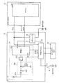
図2は、車載装置1が備えるRF受信系の機能を説明する上で必要な構成を抜粋して図示したブロック図である。なお、車載装置1には、この他にも、LF送信系の構成等が搭載されているが、図2においては、本発明の特徴部と直接関連しない構成についての図示を省略してある。
[Details of essential parts of in-vehicle equipment]
Next, the configuration of the in-vehicle device 1 will be described in more detail.
FIG. 2 is a block diagram showing an extracted configuration necessary for explaining the functions of the RF receiving system included in the in-vehicle device 1. In addition to this, the in-vehicle device 1 is equipped with a configuration of an LF transmission system and the like, but in FIG. 2, illustration of a configuration not directly related to the characteristic portion of the present invention is omitted.
図2に示すように、車載装置1は、スマートECU12とチューナ13とを備えている。また、スマートECU12は、スマートエントリーシステムの機能を制御するマイコン21を備えている。また、チューナ13は、RF帯の電波を受信するRF受信部31と、TPMSの機能を制御するTPMSマイコン33と、RF受信部31に電圧を供給するレギュレータ35とを備えている。さらに、RF受信部31は、アンテナ31A、アンテナマッチング切替回路31B、フィルタ31C、受信IC31Dなどを備えている。加えて、TPMSマイコン33には、イグニッションスイッチ41からの信号が入力し、メインボデーECU43との間でもデータの入出力が行われるようになっている。
As shown in FIG. 2, the in-vehicle device 1 includes a
次に、上記車載装置1の各部の機能と、各部がどのように作動するのかを、(A)イグニッションスイッチ41がオフの場合、(B)イグニッションスイッチ41がオンの場合に分けて説明する。
Next, the function of each part of the in-vehicle device 1 and how each part operates will be described separately for (A) when the
(A)イグニッションスイッチ41がオフの場合
まず、イグニッションスイッチ41がオフの場合について説明する。
イグニッションスイッチ41がオフの場合、TPMSマイコン33はスリープ状態になっている。一方、イグニッションスイッチ41がオフであっても、車載装置1は、携帯機3が車両周囲の無線通信エリア内に存在するか否かを確認する制御を間欠的に実行している。そのため、この制御に伴って、スマートECU12が備えるマイコン21は、電圧信号端子RCOの出力を間欠的にオンにする。
(A) When
When the
以下、電圧信号端子RCOからの出力信号がオンとなった場合について説明すると、この場合、電圧信号端子RCOからの出力信号はTPMSマイコン33およびレギュレータ35の双方に入力される。
Hereinafter, the case where the output signal from the voltage signal terminal RCO is turned on will be described. In this case, the output signal from the voltage signal terminal RCO is input to both the
ただし、ここでは、TPMSマイコン33がスリープ状態になっているので、TPMSマイコン33には電圧信号端子RCOから出力がオンになったことは無視され、TPMSマイコン33はスリープ状態を維持する。
However, since the
一方、電圧信号端子RCOからの出力信号がレギュレータ35に入力されると、レギュレータ35を介して受信IC31Dに5Vの電圧が供給される。RF受信部31は、レギュレータ35からの電圧供給がある場合に作動する一方、レギュレータ35からの電圧供給がなくなると作動を停止する。そのため、電圧信号端子RCOからの出力信号がレギュレータ35に入力された場合、受信IC31Dは作動状態になる。
On the other hand, when an output signal from the voltage signal terminal RCO is input to the
RF受信部31が作動した際、RF受信部31は、TPMSマイコン33から出力されるモード切替信号に応じて動作モードが切り替わる。具体的には、TPMSマイコン33から出力されるモード切替信号がオフの場合は、携帯機3から伝送されてくる情報を受信して、マイコン21に対して出力する第1の動作モードで作動する。一方、TPMSマイコン33から出力されるモード切替信号がオンの場合は、タイヤセンサ5から伝送されてくる情報を受信して、TPMSマイコン33に対して出力する第2の動作モードで作動する。
When the
ただし、ここでは、TPMSマイコン33がスリープ状態になっているので、TPMSマイコン33から出力されるモード切替信号はオフになっている。より詳しくは、TPMSマイコン33は、アクティブ状態になったときには、モード切替信号の出力をオンにするが、スリープ状態になったときには、モード切替信号の出力をオフにする。
However, since the
そのため、ここでは、RF受信部31は、第1の動作モードで作動することになる。より詳しく説明すると、TPMSマイコン33から出力されるモード切替信号がオフであることは、アンテナマッチング切替回路31B、受信IC31Dなどに入力される。
Therefore, here, the
アンテナマッチング切替回路31Bは、TPMSマイコン33から出力されるモード切替信号がオフである場合に、携帯機3との通信に利用するスマート用周波数に合わせた回路に切り替えられる。これにより、スマート用周波数に応じたマッチングがとられる。
When the mode switching signal output from the
また、受信IC31Dは、TPMSマイコン33から出力されるモード切替信号がオフである場合に、受信周波数が携帯機3との通信に利用するスマート用周波数に切り替えられる。
The
これらの他、フィルタ31Cにおいては、カットオフ周波数がスマート用ビットレートに応じた設定に変更される。すなわち、フィルタ31Cとしては、カットオフ周波数を可変設定可能なものが用いられており、スマート用ビットレートを利用する際には、TPMS用ビットレートよりもビットレートが低いので、カットオフ周波数を低めにすることで、ノイズ成分をより効果的にカットするようにしている。
In addition to these, in the
さらに、コンパレータの時定数なども、スマート用ビットレートに応じた設定に変更することで、リファレンスをスマート用ビットレートに追従するタイミングで変動させ、これにより、スマート用ビットレートに応じた最適なヒステリシスが得られるようにしている。 In addition, the time constant of the comparator is changed to a setting corresponding to the smart bit rate, so that the reference is changed at the timing to follow the smart bit rate, so that the optimum hysteresis according to the smart bit rate is achieved. Is to be obtained.
以上のような様々な設定が、RF受信部31においてスマート用の設定に変更されると、RF受信部31は、第1の動作モードで作動する状態になる。その結果、RF受信部31は、携帯機3から伝送されてくる情報を受信して、マイコン21に対して出力する。したがって、スマートECU12が備えるマイコン21は、携帯機3から伝送されてくる情報を取得することができる。
When the various settings as described above are changed to the smart settings in the
一方、スマートECU12が備えるマイコン21は、必要な情報が得られた時点で、電圧信号端子RCOの出力をオフにする。
以下、電圧信号端子RCOからの出力信号がオフとなった場合について説明すると、電圧信号端子RCOからの出力信号がオフになったことは、TPMSマイコン33およびレギュレータ35の双方に入力される。ただし、ここでは、TPMSマイコン33がスリープ状態になっているので、TPMSマイコン33には電圧信号端子RCOから出力がオフになったことも無視され、TPMSマイコン33はスリープ状態を維持する。
On the other hand, the
Hereinafter, the case where the output signal from the voltage signal terminal RCO is turned off will be described. The fact that the output signal from the voltage signal terminal RCO is turned off is input to both the
一方、レギュレータ35は、電圧信号端子RCOからの出力信号がオフになると、受信IC31Dへの電圧供給を停止する。そのため、RF受信部31も作動停止状態になる。RF受信部31が作動停止状態になった場合、RF受信部31は、携帯機3からの情報受信およびマイコン21に対する出力を停止する。
On the other hand, when the output signal from the voltage signal terminal RCO is turned off, the
以上のような動作は、スマートECU12が備えるマイコン21が、電圧信号端子RCOの出力を間欠的に切り替えるたびに交互に繰り返されることになる。したがって、スマートECU12は、電圧信号端子RCOの出力をオンにすることにより、RF受信部31を作動させて、携帯機3からの情報をチューナ13から入力することができ、電圧信号端子RCOの出力をオフにすることにより、RF受信部31の作動を停止させて、チューナ13からの入力を停止することができる。
The operation as described above is alternately repeated every time the
(B)イグニッションスイッチ41がオンの場合
次に、イグニッションスイッチ41がオンの場合について説明する。
イグニッションスイッチ41がオンになった場合、電圧信号端子RCOからの出力信号がオフになっていれば、TPMSマイコン33はアクティブ状態になる。
(B) When
When the
以下、電圧信号端子RCOからの出力信号がオフになっている場合について説明すると、この場合、アクティブ状態になったTPMSマイコン33からの出力信号がレギュレータ35に入力され、レギュレータ35を介して受信IC31Dに5Vの電圧が供給される。すなわち、レギュレータ35は、先に説明した電圧信号端子RCOからの出力信号の他、TPMSマイコン33からの出力信号が入力された場合にも、受信IC31Dに電圧を供給する。
Hereinafter, the case where the output signal from the voltage signal terminal RCO is turned off will be described. In this case, the output signal from the
RF受信部31は、既に説明した通り、レギュレータ35からの電圧供給がある場合に作動する一方、レギュレータ35からの電圧供給がなくなると作動を停止する。そのため、TPMSマイコン33からの出力信号がレギュレータ35に入力された場合、RF受信部31は作動状態になる。
As already described, the
RF受信部31が作動した際、既に説明した通り、RF受信部31は、TPMSマイコン33から出力されるモード切替信号に応じて動作モードが切り替わる。ここでは、TPMSマイコン33がアクティブ状態になっているので、TPMSマイコン33から出力されるモード切替信号はオンになっている。
When the
そのため、RF受信部31は、第2の動作モードで作動することになる。より詳しく説明すると、TPMSマイコン33から出力されるモード切替信号がオンであることは、アンテナマッチング切替回路31B、受信IC31Dなどに入力される。
Therefore, the
アンテナマッチング切替回路31Bは、TPMSマイコン33から出力されるモード切替信号がオンである場合に、タイヤセンサ5との通信に利用するTPMS用周波数に合わせた回路に切り替えられ、これにより、TPMS用周波数に応じたマッチングがとられる。
When the mode switching signal output from the
また、受信IC31Dは、TPMSマイコン33から出力されるモード切替信号がオンである場合に、受信周波数がタイヤセンサ5との通信に利用するTPMS用周波数に切り替えられる。
Further, the
これらの他、フィルタ31Cにおいては、カットオフ周波数がTPMS用のビットレートに応じた設定に変更され、さらに、図示しないコンパレータにおいても、時定数がTPMS用のビットレートに応じた設定に変更される。
In addition to these, in the
以上のような様々な設定が、RF受信部31においてTPMS用の設定に変更されると、RF受信部31は、第2の動作モードで作動する状態になる。その結果、RF受信部31は、タイヤセンサ5から伝送されてくる情報を受信して、その情報をTPMSマイコン33に対して出力する。したがって、TPMSマイコン33は、タイヤセンサ5から伝送されてくる情報を取得することができる。
When the various settings as described above are changed to settings for TPMS in the
ところで、イグニッションスイッチ41がオンであっても、車載装置1は、携帯機3が車両周囲の無線通信エリア内(例えば車室内)に存在するか否かを確認する制御を所定のトリガに基づいて実行している。例えば、イグニションオン中にドアが閉められた時には、携帯機3が車室外へ持ち出されていないかどうかを確認するため、ドアが閉められたことをトリガとして、スマートECU12が備えるマイコン21は、電圧信号端子RCOの出力をオンにする。
By the way, even if the
以下、電圧信号端子RCOからの出力信号がオンとなった場合について説明すると、この場合、電圧信号端子RCOからの出力信号はTPMSマイコン33およびレギュレータ35の双方に入力される。
Hereinafter, the case where the output signal from the voltage signal terminal RCO is turned on will be described. In this case, the output signal from the voltage signal terminal RCO is input to both the
そして、電圧信号端子RCOからの出力信号がTPMSマイコン33に入力された場合、TPMSマイコン33はアクティブ状態からスリープ状態に移行する。また、TPMSマイコン33がスリープ状態に移行すると、TPMSマイコン33から出力されるモード切替信号はオフに切り替わる。
When the output signal from the voltage signal terminal RCO is input to the
そのため、既に説明した様々な設定(受信周波数、アンテナマッチング、フィルタ設定、コンパレータ設定等)が、RF受信部31においてスマート用の設定に変更され、RF受信部31の動作モードは、第2の動作モードから第1の動作モードに切り替わる。その結果、RF受信部31は、携帯機3から伝送されてくる情報を受信して、マイコン21に対して出力する。したがって、スマートECU12が備えるマイコン21は、携帯機3から伝送されてくる情報を取得することができる。
Therefore, the various settings already described (reception frequency, antenna matching, filter setting, comparator setting, etc.) are changed to smart settings in the
一方、スマートECU12が備えるマイコン21は、必要な情報が得られた時点で、電圧信号端子RCOの出力をオフにする。
以下、電圧信号端子RCOからの出力信号がオフとなった場合について説明すると、電圧信号端子RCOからの出力信号がオフになったことは、TPMSマイコン33およびレギュレータ35の双方に入力される。
On the other hand, the
Hereinafter, the case where the output signal from the voltage signal terminal RCO is turned off will be described. The fact that the output signal from the voltage signal terminal RCO is turned off is input to both the
そして、電圧信号端子RCOからの出力信号がオフになった場合、TPMSマイコン33はスリープ状態からアクティブ状態に移行する。また、TPMSマイコン33がアクティブ状態に移行すると、TPMSマイコン33から出力されるモード切替信号はオンに切り替わる。
When the output signal from the voltage signal terminal RCO is turned off, the
そのため、既に説明した様々な設定(受信周波数、アンテナマッチング、フィルタ設定、コンパレータ設定等)が、RF受信部31においてTPMS用の設定に変更され、RF受信部31の動作モードは、第1の動作モードから第2の動作モードに切り替わる。その結果、RF受信部31は、タイヤセンサ5から伝送されてくる情報を受信して、その情報をTPMSマイコン33に対して出力する。したがって、TPMSマイコン33は、タイヤセンサ5から伝送されてくる情報を取得することができる。
Therefore, the various settings already described (reception frequency, antenna matching, filter setting, comparator setting, etc.) are changed to settings for TPMS in the
以上のような動作は、スマートECU12が備えるマイコン21が、電圧信号端子RCOの出力を所定のトリガに基づいて切り替えるたびに交互に繰り返されることになる。したがって、スマートECU12は、電圧信号端子RCOの出力をオンにすることにより、RF受信部31を第1の動作モードで作動させて、携帯機3からの情報をチューナ13から入力することができる。また、スマートECU12が電圧信号端子RCOの出力をオフにした際には、RF受信部31を第2の動作モードで作動させ、これにより、TPMSマイコン33は、タイヤセンサ5からの情報をチューナ13から入力することができる。
The operation as described above is alternately repeated each time the
[TPMSマイコンが実行する制御]
図3は、TPMSマイコン33が実行する制御と、その制御に伴う信号の入出力を併記したフローチャートである。
[Control executed by TPMS microcomputer]
FIG. 3 is a flowchart in which control executed by the
TPMSマイコン33は、割り込み信号(イグニッションスイッチ41からのオン信号(IG−ON)、またはスマートECU12が備えるマイコン21の電圧信号端子RCOからのオフ信号(RCO−OFF))が到来するまでは、スリープ状態で待機している(S101)。このとき、TPMSマイコン33から出力されるモード切替信号はオフである。
The
一方、S101の処理において割り込み信号が到来すると、S101の処理を抜け、TPMSマイコン33は、イグニッションスイッチ41がオンか否かを確認する(S103)。ここで、イグニッションスイッチ41がオンであれば(S103:YES)、さらに、スマートECU12が備えるマイコン21の電圧信号端子RCOからの出力がオンか否かを確認する(S105)。
On the other hand, when an interrupt signal arrives in the process of S101, the process of S101 is exited, and the
S105の処理において、電圧信号端子RCOからの出力がオフの場合(S105:NO)、TPMSマイコン33は、アクティブ状態となり、TPMS制御を実行する(S107)。このとき、TPMSマイコン33から出力されるモード切替信号はオンである。そして、このモード切替信号は、レギュレータ35、アンテナマッチング切替回路31B、受信IC31Dなどに入力され、RF受信部31は第2の動作モードで作動する。その結果、TPMSマイコン33は、受信IC31Dから伝送されてくる情報を取得することになる。
In the process of S105, when the output from the voltage signal terminal RCO is off (S105: NO), the
こうしてS105の処理を終えたら、S103の処理へと戻り、以降は、イグニッションスイッチ41がオン(S103:YES)、且つ、電圧信号端子RCOからの出力がオフである間は(S105:NO)、S103〜S107の処理を繰り返すことになる。
When the process of S105 is completed in this way, the process returns to the process of S103, and thereafter, while the
一方、S103〜S107の処理を繰り返す中で、イグニッションスイッチ41がオフにされた場合は(S103:NO)、S101の処理へと戻る。また、S103〜S107の処理を繰り返す中で、電圧信号端子RCOからの出力がオンになった場合も(S105:YES)、S101の処理へと戻る。
On the other hand, when the
S101の処理へと戻った場合、TPMSマイコン33はスリープ状態となり、この状態は再び割り込み信号が到来するまで続くことになる。
[チューナへの入力信号と各部の状態]
図4は、イグニッションスイッチ41のオン/オフと電圧信号端子RCOからの出力のオン/オフとの組み合わせに応じて、受信IC31Dによる受信周波数、フィルタ31Cやコンパレータ等の設定、アンテナマッチング切替回路31Bによるアンテナマッチング、およびTPMSマイコン33の作動状態が、どのように切り替えられるかを一覧表にしたものである。
When returning to the processing of S101, the
[Input signal to tuner and status of each part]
FIG. 4 shows the reception frequency by the
図4に示すように、車載装置1では、イグニッションスイッチ41がオフで、電圧信号端子RCOからの出力がオフの場合、TPMSマイコン33はスリープ状態となり、受信IC31Dによる受信も停止するので、この場合は、電力消費が最も抑制される状態になる。
As shown in FIG. 4, in the in-vehicle device 1, when the
一方、電圧信号端子RCOからの出力がオンになった場合は、イグニッションスイッチ41がオンかオフかを問わず、各部の設定等はスマートエントリーシステム用に切り替えられる。具体的には、受信IC31Dによる受信周波数はスマート用周波数に切り替えられ、フィルタ31Cやコンパレータ等の設定もスマートエントリーシステム用の設定がなされ、アンテナマッチング切替回路31Bもスマート用周波数に応じた回路に切り替えられる。
On the other hand, when the output from the voltage signal terminal RCO is turned on, the setting of each part is switched for the smart entry system regardless of whether the
したがって、スマートECU12が電圧信号端子RCOからの出力をオンにした場合は、イグニッションスイッチ41がオンかオフかを問わず、スマートエントリーシステムとしての機能が作動することになる。ただし、この場合も、TPMSマイコン33は、スリープ状態になる。
Therefore, when the
また一方、イグニッションスイッチ41がオンの状態で、電圧信号端子RCOからの出力がオフになった場合、各部の設定等はTPMS用に切り替えられる。具体的には、受信IC31Dによる受信周波数はTPMS用周波数に切り替えられ、フィルタ31Cやコンパレータ等の設定もTPMS用の設定がなされ、アンテナマッチング切替回路31BもTPMS用周波数に応じた回路に切り替えられる。また、この場合、TPMSマイコン33は、アクティブ状態になる。
On the other hand, when the
したがって、イグニッションスイッチ41がオンの状態で、電圧信号端子RCOからの出力がオフになった場合には、TPMS機能が作動することになる。
なお、以上説明したように、チューナ13の各部の動作状態は、チューナ13への入力信号に応じて図4に示した通りに切り替わる。この切替を実現するに当たって、本実施形態では、TPMSマイコン33およびレギュレータ35が信号を入力して、受信IC31Dへの電圧供給とモード切替信号のオン/オフを制御する方式を採用したが、同様の切替を実現できる回路構成であれば、上記実施形態以外の回路構成を採用してもよい。例えば、TPMSマイコン33によるソフトウェア制御を行わなくても、ハードウェアロジックを組み込んで、図4に示した各状態への切替を行うように構成してもよい。
Accordingly, when the
As described above, the operating state of each part of the
[スマートエントリー機能単独のシステムとの比較]
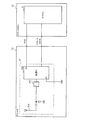
図5は、スマートエントリー機能のみを備える既存のシステム(スマートエントリーシステム)が備える車載装置の一例を図示したブロック図である。図5において、図2に示した構成と同等な構成に対しては同じ符号を付してある。
[Comparison with system with smart entry function alone]
FIG. 5 is a block diagram illustrating an example of an in-vehicle device included in an existing system (smart entry system) having only a smart entry function. In FIG. 5, the same reference numerals are given to the same components as those shown in FIG.
図5に示す車載装置において、受信IC31Dは、スマートECU12に対してのみ受信データを提供するように構成されており、この点で、TPMSマイコン33に対して受信データを供給していた車載装置1(図2参照)とは異なる構成になっている。
In the in-vehicle device shown in FIG. 5, the
ただし、このように受信IC31Dは、スマートECU12に対してのみ受信データを提供するので、スマートECU12に対して完全に従動すればよい。そのため、受信IC31Dは、スマートECU12が備える電圧信号端子RCOから電圧供給を受けたときに作動する仕組みになっている。
However, since the
すなわち、このような既存のスマートエントリーシステムにおいて、スマートECU12が備える電圧信号端子RCOは、本来、受信IC31Dに対して電圧を供給するために設けられていたものである。
That is, in such an existing smart entry system, the voltage signal terminal RCO provided in the
これに対し、図2に示した車載装置1においては、スマートECU12を既存のスマートエントリーシステムと全く同等に構成するとともに、スマートECU12が備える電圧信号端子RCOについては、スマートECU12からチューナ13へスマートエントリーシステム機能の作動を伝達するための信号線として利用した。
On the other hand, in the in-vehicle device 1 shown in FIG. 2, the
このような構成を採用すれば、図2および図5を対比すると明らかなように、スマートECU12とチューナ13(あるいはRF受信部31)との間のインターフェースは、既存のスマートエントリーシステムと、全く同等になる。すなわち、スマートECU12は、TPMS機能の有無にかかわらず、まったく同じハードウェア構成および仕様になる。
If such a configuration is adopted, the interface between the
したがって、上記車載装置1においては、既存のスマートエントリーシステムで採用されているスマートECU12を、そのまま利用することが可能である。逆に言えば、上記スマートECU12は、既存のスマートエントリーシステムで採用されている機器と同等な機能を持つ機器(=図5に示したチューナ13)と組み合わせることで、TPMSとしての構成を持たないスマートエントリーシステムを構成する際にも利用できる。
Therefore, in the in-vehicle device 1, the
[実施形態の効果]
以上説明した通り、上記のように構成された車両用複合制御システムによれば、スマートエントリーシステムとしての機能およびTPMSとしての機能を、双方とも適切に制御することができる。
[Effect of the embodiment]
As described above, according to the vehicle composite control system configured as described above, both the function as the smart entry system and the function as the TPMS can be appropriately controlled.
また、上記車載装置1が備えるスマートECU12であれば、TPMSとしての構成を持たないスマートエントリーシステムとの共用化を図ることもできるので、共用化に伴う量産効果によってコストダウンを図ることができ、TPMSとしての構成を持つシステム専用に設計された車載装置を備える場合に比べ、車載装置1を安価に提供できるようになる。 Moreover, if it is smart ECU12 with which the said vehicle-mounted apparatus 1 is provided, since it can also share with the smart entry system which does not have a structure as TPMS, it can aim at cost reduction by the mass-production effect accompanying sharing, Compared with the case where an in-vehicle device designed exclusively for a system having a configuration as a TPMS is provided, the in-vehicle device 1 can be provided at a low cost.
また、上記車載装置1は、車両のイグニッションスイッチ41がオフ、且つ、電圧信号端子RCOからの出力信号がオフの期間に、RF受信部31が作動を停止するので、RF受信部31が常時作動を続けるものに比べ、省電力化を図ることができる。
Further, in the on-vehicle apparatus 1, the operation of the
また、上記車載装置1は、車両のイグニッションスイッチ41がオンとなった場合、または、電圧信号端子RCOからの出力信号がオンとなった場合に、レギュレータ35が電力をRF受信部31に対して供給し、その電力でRF受信部31が作動する。したがって、RF受信部31は、レギュレータ35から電力が供給されるか否かに応じて受動的に作動したり作動を停止したりするので、RF受信部31が自ら省電力制御を実行しなくてもよく、そのような省電力制御を実行するための高度な仕組みをRF受信部31に実装しなくてもよい。
Further, in the on-vehicle device 1, the
また、上記車載装置1では、TPMSマイコン33は、車両のイグニッションスイッチがオン、且つ、電圧信号端子RCOからの出力信号がオフとなった場合に、RF受信部31に対してモード切替信号を出力する。RF受信部31は、レギュレータ35から電力が供給された際、TPMSマイコン33からモード切替信号が出力されていなければ、第1の動作モードで作動する。また、RF受信部31は、レギュレータ35から電力が供給された際、TPMSマイコン33からモード切替信号が出力されていれば、第2の動作モードで作動する。
In the in-vehicle device 1, the
したがって、RF受信部31は、モード切替信号の有無だけで第1,第2いずれの動作モードで作動するのかを切り替えることができる。よって、車両のイグニッションスイッチの状態とスマートECU12からの出力信号の有無とを組み合わせて判定するような仕組みをRF受信部31に実装しなくてもよい。
Therefore, the
また、車載装置1において、TPMSマイコン33は、アクティブ状態またはスリープ状態になり、アクティブ状態になるとRF受信部31に対してモード切替信号を出力する。
In the in-vehicle device 1, the
したがって、スリープ状態へ移行した際には、スリープ状態へ移行しないものに比べ、省電力化を図ることができ、しかも、アクティブ状態に移行した際には、RF受信部31からの情報出力が行われ、その情報を取得することができる。
Therefore, when shifting to the sleep state, it is possible to save power compared to those not shifting to the sleep state, and when shifting to the active state, information output from the
[変形例等]
以上、本発明の実施形態について説明したが、本発明は上記の具体的な一実施形態に限定されず、この他にも種々の形態で実施することができる。
[Modifications, etc.]
As mentioned above, although embodiment of this invention was described, this invention is not limited to said specific one Embodiment, In addition, it can implement with a various form.
例えば、上記実施形態では、情報伝送を行う際のビットレートとして、スマート用ビットレートがTPMS用ビットレートよりも低い例を示したが、これに限定されず、各ビットレートは、それぞれ任意に選定することができる。また、各ビットレートを任意に選定できるので、フィルタ31C等の設定についても適宜最適化を図ればよい。
For example, in the above-described embodiment, an example in which the bit rate for smart transmission is lower than the bit rate for TPMS is shown as the bit rate for information transmission. However, the bit rate is not limited to this, and each bit rate is arbitrarily selected. can do. Further, since each bit rate can be arbitrarily selected, the setting of the
具体例を挙げれば、スマート用ビットレートがTPMS用ビットレートが同じであってもよく、この場合、フィルタ31Cの特性やコンパレータの特性は可変調整できない構成になっていてもよい。
As a specific example, the smart bit rate may be the same as the TPMS bit rate. In this case, the
1・・・車載装置、3・・・携帯機、5・・・タイヤセンサ、12・・・スマートECU、13・・・チューナ、21・・・マイコン、31・・・RF受信部、31A・・・アンテナ、31B・・・アンテナマッチング切替回路、31C・・・フィルタ、31D・・・受信IC、33・・・TPMSマイコン、35・・・レギュレータ、41・・・イグニッションスイッチ、43・・・メインボデーECU。 DESCRIPTION OF SYMBOLS 1 ... In-vehicle apparatus, 3 ... Portable machine, 5 ... Tire sensor, 12 ... Smart ECU, 13 ... Tuner, 21 ... Microcomputer, 31 ... RF receiver, 31A. .. Antenna, 31B ... Antenna matching switching circuit, 31C ... Filter, 31D ... Receiver IC, 33 ... TPMS microcomputer, 35 ... Regulator, 41 ... Ignition switch, 43 ... Main body ECU.
Claims (6)
前記車両が備えるタイヤの状態を検出する検出手段との間で無線通信を行うことにより、前記検出手段から伝送されてくる前記タイヤの状態に関する情報を取得するタイヤ空気圧監視システム用の第2制御手段と、
前記携帯機から伝送されてくる情報を受信して、前記第1制御手段に対して出力する第1の動作モード、および前記検出手段から伝送されてくる情報を受信して、前記第2制御手段に対して出力する第2の動作モードを、いずれかに切り替えて作動可能な受信手段と
を備え、
前記受信手段は、前記車両のイグニッションスイッチがオンまたはオフいずれであっても、前記第1制御手段からの出力信号がオンとなった場合には、前記第1の動作モードに切り替えられる一方、前記車両のイグニッションスイッチがオン、且つ、前記第1制御手段からの出力信号がオフとなった場合には、前記第2の動作モードに切り替えられ、
前記第1制御手段は、間欠的または所定のトリガに基づいて前記出力信号をオンにするとともに、当該出力信号がオンとなった場合には、前記受信手段から出力される前記携帯機からの情報を入力し、
前記第2制御手段は、前記車両のイグニッションスイッチがオン、且つ、前記第1制御手段からの出力信号がオフとなった場合には、前記受信手段から出力される前記検出手段からの情報を入力する
ことを特徴とする車両用複合制御システムの車載装置。 A first control means for a smart entry system that performs authentication necessary to allow execution of various controls in the vehicle by performing wireless communication with a portable device possessed by a user of the vehicle;
Second control means for a tire air pressure monitoring system that acquires information on the state of the tire transmitted from the detection means by performing wireless communication with a detection means for detecting the state of the tire included in the vehicle. When,
A first operation mode for receiving information transmitted from the portable device and outputting the information to the first control means; and a second operation means for receiving information transmitted from the detection means. Receiving means operable to switch the second operation mode to be output to any one of
The receiving means is switched to the first operation mode when the output signal from the first control means is on regardless of whether the ignition switch of the vehicle is on or off. When the ignition switch of the vehicle is turned on and the output signal from the first control means is turned off, the vehicle is switched to the second operation mode,
The first control means turns on the output signal intermittently or based on a predetermined trigger, and when the output signal is turned on, information from the portable device output from the receiving means Enter
The second control means inputs information from the detection means that is output from the reception means when the ignition switch of the vehicle is on and the output signal from the first control means is off. An in-vehicle device for a composite control system for a vehicle.
ことを特徴とする請求項1に記載の車両用複合制御システムの車載装置。 The second control means becomes active when the ignition switch of the vehicle is turned on and the output signal from the first control means is turned off, while the ignition switch of the vehicle is turned off. 2. The vehicle composite according to claim 1, wherein when the output signal from the first control means is turned on, the vehicle is in a sleep state in which power consumption can be suppressed more than in the active state. In-vehicle device for control system.
ことを特徴とする請求項1または請求項2に記載の車両用複合制御システムの車載装置。 The reception means, the ignition switch is off the vehicle, and, when said output signal from is turned off first control means, according to claim, characterized in that become deactivated state 1 or claim 2 The vehicle-mounted apparatus of the composite control system for vehicles described in 2.
を備えることを特徴とする請求項3に記載の車両用複合制御システムの車載装置。 When the ignition switch of the vehicle is turned on, or when the output signal from the first control means is turned on, the power required for the receiving means to operate is supplied to the receiving means. The in-vehicle device of the composite control system for a vehicle according to claim 3 , further comprising a power supply unit for supplying the power .
前記受信手段は、前記電力供給手段から電力が供給された際、前記第2制御手段から前記モード切替信号が出力されていなければ、前記第1の動作モードで作動する一方、前記第2制御手段から前記モード切替信号が出力されていれば、前記第2の動作モードで作動する
ことを特徴とする請求項4に記載の車両用複合制御システムの車載装置。 The second control means outputs a mode switching signal to the receiving means when an ignition switch of the vehicle is turned on and an output signal from the first control means is turned off,
When the power is supplied from the power supply means, the receiving means operates in the first operation mode unless the mode switching signal is output from the second control means, while the second control means 5. The in-vehicle device of the composite control system for a vehicle according to claim 4 , wherein the vehicle operates in the second operation mode if the mode switching signal is output from the vehicle.
Priority Applications (3)
| Application Number | Priority Date | Filing Date | Title |
|---|---|---|---|
| JP2007271492A JP4552995B2 (en) | 2007-10-18 | 2007-10-18 | In-vehicle device and composite control system for vehicle |
| DE200810051273 DE102008051273A1 (en) | 2007-10-18 | 2008-10-10 | In-vehicle device and combined vehicle control system |
| US12/252,864 US7952472B2 (en) | 2007-10-18 | 2008-10-16 | In-vehicle device and vehicular combined control system |
Applications Claiming Priority (1)
| Application Number | Priority Date | Filing Date | Title |
|---|---|---|---|
| JP2007271492A JP4552995B2 (en) | 2007-10-18 | 2007-10-18 | In-vehicle device and composite control system for vehicle |
Publications (2)
| Publication Number | Publication Date |
|---|---|
| JP2009097272A JP2009097272A (en) | 2009-05-07 |
| JP4552995B2 true JP4552995B2 (en) | 2010-09-29 |
Family
ID=40514605
Family Applications (1)
| Application Number | Title | Priority Date | Filing Date |
|---|---|---|---|
| JP2007271492A Expired - Fee Related JP4552995B2 (en) | 2007-10-18 | 2007-10-18 | In-vehicle device and composite control system for vehicle |
Country Status (3)
| Country | Link |
|---|---|
| US (1) | US7952472B2 (en) |
| JP (1) | JP4552995B2 (en) |
| DE (1) | DE102008051273A1 (en) |
Cited By (5)
| Publication number | Priority date | Publication date | Assignee | Title |
|---|---|---|---|---|
| JP2013043535A (en) * | 2011-08-24 | 2013-03-04 | Honda Motor Co Ltd | In-vehicle device of vehicle with smart key system and tire air pressure monitoring system |
| EP2669098A1 (en) | 2012-05-30 | 2013-12-04 | Kabushiki Kaisha Tokai Rika Denki Seisakusho | Multifunction receiver |
| JP2014051249A (en) * | 2012-09-10 | 2014-03-20 | Tokai Rika Co Ltd | Receiver |
| JP2016108826A (en) * | 2014-12-08 | 2016-06-20 | 株式会社デンソー | Communication system |
| WO2020003843A1 (en) | 2018-06-28 | 2020-01-02 | 株式会社デンソー | Tire pressure monitoring system and tire pressure monitoring method |
Families Citing this family (18)
| Publication number | Priority date | Publication date | Assignee | Title |
|---|---|---|---|---|
| US7944347B2 (en) * | 2007-11-11 | 2011-05-17 | Doran Manufacturing Llc | Apparatus for accelerating sensor reading upon start-up |
| FR2938991B1 (en) * | 2008-11-21 | 2012-04-13 | Valeo Securite Habitacle | COMMUNICATION SYSTEM FOR MOTOR VEHICLE. |
| JP5233951B2 (en) * | 2009-10-19 | 2013-07-10 | トヨタ自動車株式会社 | Vehicle communication system |
| US8564428B2 (en) | 2010-06-15 | 2013-10-22 | Honda Motor Co., Ltd. | Memorizing location of tires in TPMS and smart entry system |
| JP5392209B2 (en) | 2010-09-14 | 2014-01-22 | 株式会社デンソー | In-vehicle device |
| JP5643596B2 (en) | 2010-10-21 | 2014-12-17 | 株式会社東芝 | In-vehicle device control system |
| JP2012101704A (en) * | 2010-11-11 | 2012-05-31 | Tokai Rika Co Ltd | Onboard communication instrument |
| JP2012101705A (en) * | 2010-11-11 | 2012-05-31 | Tokai Rika Co Ltd | On-vehicle communication device |
| JP5798398B2 (en) * | 2011-07-25 | 2015-10-21 | トヨタ自動車株式会社 | Wireless communication system, receiver and communication method |
| US8896418B2 (en) | 2011-09-16 | 2014-11-25 | Honda Motor Co., Ltd. | Method to increase accuracy of locating unit in wireless vehicle system |
| JP5706363B2 (en) | 2012-03-19 | 2015-04-22 | 株式会社東芝 | Wireless communication device |
| JP5811014B2 (en) * | 2012-04-06 | 2015-11-11 | 株式会社デンソー | In-vehicle receiver |
| JP6060665B2 (en) | 2012-12-13 | 2017-01-18 | 株式会社デンソー | Tire theft alarm system |
| US8935069B2 (en) | 2013-02-28 | 2015-01-13 | Bendix Commercial Vechicle Systems LLC | System and method for transmitting a tire pressure status signal to a vehicle ECU |
| KR101548954B1 (en) | 2014-01-13 | 2015-09-01 | 현대자동차주식회사 | Tire pressure management system with enhanced wireless security and method for controlling thereof |
| JP6265480B2 (en) * | 2014-02-19 | 2018-01-24 | アルプス電気株式会社 | In-vehicle composite system and in-vehicle device |
| JP6830802B2 (en) * | 2016-11-28 | 2021-02-17 | 旭化成エレクトロニクス株式会社 | Wireless system and receiving circuit |
| US11458781B1 (en) | 2020-11-09 | 2022-10-04 | Marc Tobias | System for vehicle monitoring utilizing tire pressure sensors |
Citations (2)
| Publication number | Priority date | Publication date | Assignee | Title |
|---|---|---|---|---|
| JP2005157511A (en) * | 2003-11-21 | 2005-06-16 | Toyota Motor Corp | Vehicular information processing system and wheel information processing system |
| JP3789335B2 (en) * | 2001-09-13 | 2006-06-21 | アルプス電気株式会社 | Keyless entry device that also functions as a tire pressure monitor |
Family Cites Families (10)
| Publication number | Priority date | Publication date | Assignee | Title |
|---|---|---|---|---|
| US5463374A (en) * | 1994-03-10 | 1995-10-31 | Delco Electronics Corporation | Method and apparatus for tire pressure monitoring and for shared keyless entry control |
| US6420967B1 (en) * | 2001-01-31 | 2002-07-16 | Lear Corporation | System and method for shared vehicle tire pressure monitoring, remote keyless entry, and vehicle immobilization |
| EP1361963B1 (en) * | 2001-02-20 | 2007-01-24 | Siemens VDO Automotive Corporation | Combined tire pressure monitoring and keyless entry receiver |
| DE602004016265D1 (en) * | 2003-11-19 | 2008-10-16 | Siemens Vdo Automotive Corp | Asynchronous nesting of RF signals |
| JP2005236556A (en) * | 2004-02-18 | 2005-09-02 | Denso Corp | Receiver and electronic apparatus |
| US20070164876A1 (en) * | 2006-01-11 | 2007-07-19 | Siemens Vdo Automotive Corporation | Receiver for different frequencies and modulations |
| US7639122B2 (en) * | 2006-10-30 | 2009-12-29 | Spx Corporation | Tire pressure monitor system tool with vehicle entry system |
| US20080100429A1 (en) * | 2006-11-01 | 2008-05-01 | Lear Corporation | Tire pressure monitoring (tpm) and remote keyless entry (rke) system for a vehicle |
| US7650864B2 (en) * | 2006-11-17 | 2010-01-26 | Magna Electronics Inc. | Remote starter for vehicle |
| US20080150712A1 (en) * | 2006-12-21 | 2008-06-26 | Ford Global Technologies, Llc | Tire pressure monitoring (tpm) and remote keyless entry (rke) system |
-
2007
- 2007-10-18 JP JP2007271492A patent/JP4552995B2/en not_active Expired - Fee Related
-
2008
- 2008-10-10 DE DE200810051273 patent/DE102008051273A1/en not_active Withdrawn
- 2008-10-16 US US12/252,864 patent/US7952472B2/en not_active Expired - Fee Related
Patent Citations (2)
| Publication number | Priority date | Publication date | Assignee | Title |
|---|---|---|---|---|
| JP3789335B2 (en) * | 2001-09-13 | 2006-06-21 | アルプス電気株式会社 | Keyless entry device that also functions as a tire pressure monitor |
| JP2005157511A (en) * | 2003-11-21 | 2005-06-16 | Toyota Motor Corp | Vehicular information processing system and wheel information processing system |
Cited By (8)
| Publication number | Priority date | Publication date | Assignee | Title |
|---|---|---|---|---|
| JP2013043535A (en) * | 2011-08-24 | 2013-03-04 | Honda Motor Co Ltd | In-vehicle device of vehicle with smart key system and tire air pressure monitoring system |
| EP2669098A1 (en) | 2012-05-30 | 2013-12-04 | Kabushiki Kaisha Tokai Rika Denki Seisakusho | Multifunction receiver |
| US9114670B2 (en) | 2012-05-30 | 2015-08-25 | Kabushiki Kaisha Tokai Rika Denki Seisakusho | Multifunction receiver |
| JP2014051249A (en) * | 2012-09-10 | 2014-03-20 | Tokai Rika Co Ltd | Receiver |
| JP2016108826A (en) * | 2014-12-08 | 2016-06-20 | 株式会社デンソー | Communication system |
| US10160421B2 (en) | 2014-12-08 | 2018-12-25 | Denso Corporation | Communication system |
| WO2020003843A1 (en) | 2018-06-28 | 2020-01-02 | 株式会社デンソー | Tire pressure monitoring system and tire pressure monitoring method |
| US11740318B2 (en) | 2018-06-28 | 2023-08-29 | Denso Corporation | Tire pressure monitoring system and tire pressure monitoring method |
Also Published As
| Publication number | Publication date |
|---|---|
| JP2009097272A (en) | 2009-05-07 |
| DE102008051273A1 (en) | 2009-05-07 |
| US7952472B2 (en) | 2011-05-31 |
| US20090102634A1 (en) | 2009-04-23 |
Similar Documents
| Publication | Publication Date | Title |
|---|---|---|
| JP4552995B2 (en) | In-vehicle device and composite control system for vehicle | |
| US20140368313A1 (en) | Vehicle keyfob with accelerometer to extend battery life | |
| US8284040B2 (en) | Receiver system for vehicles | |
| US20080100429A1 (en) | Tire pressure monitoring (tpm) and remote keyless entry (rke) system for a vehicle | |
| JP2008014019A (en) | Keyless device for vehicle | |
| US20070030119A1 (en) | Communication apparatus for vehicle | |
| JP2018204311A (en) | Vehicle control system | |
| JP5815472B2 (en) | Integrated receiver | |
| JP4435632B2 (en) | Keyless entry device | |
| JP2010064722A (en) | Vehicular operation monitoring system | |
| US8847744B2 (en) | Vehicle receiver system, vehicle receiver, and operating method for vehicle receiver | |
| JP4315028B2 (en) | Smart keyless system | |
| US8843091B2 (en) | Remote keyless entry and tire pressure monitoring radio communication system, receiver, and communication method that switches a reception mode of a receiver between a first reception mode and a second reception mode | |
| JP5779137B2 (en) | Integrated receiver | |
| JP2004268612A (en) | Tire air pressure monitoring system | |
| JP2006152763A (en) | On-vehicle communication control system | |
| US8983561B2 (en) | In-vehicle apparatus | |
| JP5666966B2 (en) | Integrated tuner | |
| JP2012101706A (en) | On-vehicle communication device | |
| JP5587741B2 (en) | In-vehicle communication device | |
| WO2023136016A1 (en) | In-vehicle receiver and system for monitoring tire pressure | |
| JP2008174961A (en) | Keyless system for vehicle | |
| JP4775216B2 (en) | Keyless device for vehicle | |
| JP2012101705A (en) | On-vehicle communication device | |
| JP5502770B2 (en) | Function integrated wireless communication system |
Legal Events
| Date | Code | Title | Description |
|---|---|---|---|
| A621 | Written request for application examination |
Free format text: JAPANESE INTERMEDIATE CODE: A621 Effective date: 20090512 |
|
| A977 | Report on retrieval |
Free format text: JAPANESE INTERMEDIATE CODE: A971007 Effective date: 20091001 |
|
| A131 | Notification of reasons for refusal |
Free format text: JAPANESE INTERMEDIATE CODE: A131 Effective date: 20091020 |
|
| A521 | Request for written amendment filed |
Free format text: JAPANESE INTERMEDIATE CODE: A523 Effective date: 20091221 |
|
| TRDD | Decision of grant or rejection written | ||
| A01 | Written decision to grant a patent or to grant a registration (utility model) |
Free format text: JAPANESE INTERMEDIATE CODE: A01 Effective date: 20100622 |
|
| A01 | Written decision to grant a patent or to grant a registration (utility model) |
Free format text: JAPANESE INTERMEDIATE CODE: A01 |
|
| A61 | First payment of annual fees (during grant procedure) |
Free format text: JAPANESE INTERMEDIATE CODE: A61 Effective date: 20100705 |
|
| FPAY | Renewal fee payment (event date is renewal date of database) |
Free format text: PAYMENT UNTIL: 20130723 Year of fee payment: 3 |
|
| R151 | Written notification of patent or utility model registration |
Ref document number: 4552995 Country of ref document: JP Free format text: JAPANESE INTERMEDIATE CODE: R151 |
|
| FPAY | Renewal fee payment (event date is renewal date of database) |
Free format text: PAYMENT UNTIL: 20130723 Year of fee payment: 3 |
|
| R250 | Receipt of annual fees |
Free format text: JAPANESE INTERMEDIATE CODE: R250 |
|
| R250 | Receipt of annual fees |
Free format text: JAPANESE INTERMEDIATE CODE: R250 |
|
| R250 | Receipt of annual fees |
Free format text: JAPANESE INTERMEDIATE CODE: R250 |
|
| R250 | Receipt of annual fees |
Free format text: JAPANESE INTERMEDIATE CODE: R250 |
|
| R250 | Receipt of annual fees |
Free format text: JAPANESE INTERMEDIATE CODE: R250 |
|
| R250 | Receipt of annual fees |
Free format text: JAPANESE INTERMEDIATE CODE: R250 |
|
| R250 | Receipt of annual fees |
Free format text: JAPANESE INTERMEDIATE CODE: R250 |
|
| R250 | Receipt of annual fees |
Free format text: JAPANESE INTERMEDIATE CODE: R250 |
|
| LAPS | Cancellation because of no payment of annual fees |