JP4552182B2 - Front bumper structure - Google Patents
Front bumper structure Download PDFInfo
- Publication number
- JP4552182B2 JP4552182B2 JP2004232973A JP2004232973A JP4552182B2 JP 4552182 B2 JP4552182 B2 JP 4552182B2 JP 2004232973 A JP2004232973 A JP 2004232973A JP 2004232973 A JP2004232973 A JP 2004232973A JP 4552182 B2 JP4552182 B2 JP 4552182B2
- Authority
- JP
- Japan
- Prior art keywords
- bumper
- air inlet
- pin
- edge
- upper bumper
- Prior art date
- Legal status (The legal status is an assumption and is not a legal conclusion. Google has not performed a legal analysis and makes no representation as to the accuracy of the status listed.)
- Expired - Fee Related
Links
Images
Landscapes
- Vehicle Interior And Exterior Ornaments, Soundproofing, And Insulation (AREA)
- Body Structure For Vehicles (AREA)
Description
本発明は、フロントバンパ構造に関し、詳しくは、アッパーバンパとロアバンパとを形成し、それらを互いに結合させて全体を構成するフロントバンパ構造に関するものである。 The present invention relates to a front bumper structure, and in particular, relates to a front bumper structure in which an upper bumper and a lower bumper are formed, and they are combined with each other to constitute the whole.
大型のバンパを成形する際に、成形型に充分な大きさがある場合は、1つの型でバンパを成形することができる。しかしながら、大きな成形型がない場合には、バンパをアッパーバンパとロアバンパとに2分割し、それらを互いに結合させるようにしたものがある(例えば、特許文献1参照)。
この特許文献1に開示されているフロントバンパでは、ロアバンパの上部とアッパーバンパの下部に、それぞれフランジを形成し、それらのフランジを重ね合わせるようにして、ロアバンパとアッパーバンパを組み付けている。
In the front bumper disclosed in Patent Document 1, flanges are formed on an upper part of the lower bumper and a lower part of the upper bumper, respectively, and the lower bumper and the upper bumper are assembled so as to overlap the flanges.
特許文献1のバンパでは、アッパーバンパまたはロアバンパに、成形時またはその後の変形で、長手方向(幅方向)に歪みが生じると、アッパーバンパとロアバンパとの境界の見切り間隙が不均一になり、見栄えが悪くなる虞がある。 In the bumper of Patent Document 1, if the upper bumper or the lower bumper is deformed during molding or after deformation in the longitudinal direction (width direction), the parting gap at the boundary between the upper bumper and the lower bumper becomes uneven and looks good May get worse.
本発明は、上記課題を解決し、アッパーバンパとロアバンパの分割部をできるだけ目立たなくして、見栄えをよくしたフロントバンパ構造を提供することを目的とする。 An object of the present invention is to solve the above-mentioned problems and to provide a front bumper structure that improves the appearance by making the divided portions of the upper bumper and the lower bumper as inconspicuous as possible.
本発明は、上記課題を解決するため、アッパーバンパとロアバンパとを互いに結合させることによって構成され、前面中央部に、幅方向に長い空気流入口が形成され、前記アッパーバンパの空気流入口よりも上部に、フロントグリルの開口を配設するフロントバンパ構造において、
アッパーバンパとロアバンパの分割線を、前記空気流入口の上縁に沿って位置させ、前記アッパーバンパの裏面に、前記空気流入口の上縁と前記開口の下縁を繋いで補強する架橋部を一体に形成し、前記架橋部を前記アッパーバンパの裏面から間隙をもって配設し、前記架橋部は、フロントグリルで隠される前記フロントグリルの開口の下面と前記アッパーバンパの下縁に形成された後方に向かって延びるフランジに接続され、前記架橋部には、車体後方に突出するピンが形成され、前記ロアバンパに、前記ピンが挿入されるピン挿入孔を形成し、前記ピンを前記ピン挿入孔に挿入させることによって、前記アッパーバンパをロアバンパに位置決めさせるようにしたことにある。
また、本発明は、前記分割線を空気流入口の上縁に沿って位置させるとともに、前記ロアバンパに、前記空気流入口の上縁から上方に突出するフランジを形成し、該フランジに、前記ピン挿入孔を形成したことにある。
In order to solve the above-mentioned problems, the present invention is configured by connecting an upper bumper and a lower bumper to each other, and an air inlet that is long in the width direction is formed in the front center portion, and is more than the air inlet of the upper bumper. the top, in the front bumper structure arranged the opening of the front grill,
The dividing line of the upper bumper and Roabanpa, are positioned along the air inlet of the upper edge, on the back surface of the upper bumper, the bridge portion which reinforces by connecting the lower edge of the upper edge and the opening of the air inlet The bridge portion is formed integrally with a gap from the back surface of the upper bumper, and the bridge portion is formed on the lower surface of the opening of the front grill concealed by the front grill and the lower edge of the upper bumper. A pin that protrudes toward the rear of the vehicle body is formed in the bridging portion, a pin insertion hole into which the pin is inserted is formed in the lower bumper, and the pin is used as the pin insertion hole. The upper bumper is positioned on the lower bumper by being inserted.
In the present invention , the dividing line is positioned along the upper edge of the air inlet, and a flange projecting upward from the upper edge of the air inlet is formed on the lower bumper, and the pin is provided on the flange. The insertion hole is formed.
本発明によれば、アッパーバンパとロアバンパの分割線を、前記空気流入口の上縁に沿って位置させ、前記アッパーバンパの裏面に、前記空気流入口の上縁と前記開口の下縁を繋いで補強する架橋部を一体に形成し、前記架橋部を前記アッパーバンパの裏面から間隙をもって配設し、前記架橋部は、フロントグリルで隠される前記フロントグリルの開口の下面と前記アッパーバンパの下縁に形成された後方に向かって延びるフランジに接続され、前記架橋部には、車体後方に突出するピンが形成され、前記ロアバンパに、前記ピンが挿入されるピン挿入孔を形成し、前記ピンを前記ピン挿入孔に挿入させることによって、前記アッパーバンパをロアバンパに位置決めさせるようにしたので、少なくとも空気流入口の縁部では、両バンパの分割部が目立たない。バンパの上下色分けの場合に、分割すると塗装が容易になる。また、アッパーバンパの裏面に、車体の内方に突出するピンを形成するとともに、ロアバンパに、前記ピンが挿入されるピン挿入孔を形成し、前記ピンを前記ピン挿入孔に挿入させることによって、前記アッパーバンパをロアバンパに位置決めさせるようにしたので、ロアバンパに対してアッパーバンパを仮保持できることから、アッパーバンパとロアバンパとの組付けが容易になり、バンパ組付け後においては、突起によりロアバンパの吊り下げ力が大きくなる。またさらに、アッパーバンパの空気流入口よりも上部に、フロントグリルの開口を配設するとともに、前記空気流入口の上縁と前記開口の下縁を繋ぐ架橋部を一体に形成したので、空気流入口間を補強することができる。また、本発明によれば、架橋部を前記アッパーバンパの裏面から間隙をもって配設したので、アッパーバンパの表面にヒケが生じるのを防止することができる。
さらに、本発明によれば、分割線を空気流入口の上縁に沿って位置させるとともに、前記ロアバンパに、前記空気流入口の上縁から上方に突出するフランジを形成し、該フランジに、前記ピン挿入孔を形成したので、フランジにより、ロアバンパ側の空気流入口の補強が図れる。
According to the present invention, the dividing line between the upper bumper and the lower bumper is positioned along the upper edge of the air inlet, and the upper edge of the air inlet and the lower edge of the opening are connected to the back surface of the upper bumper. A bridge portion to be reinforced is integrally formed, and the bridge portion is disposed with a gap from a back surface of the upper bumper, and the bridge portion is provided under the front grille and the lower surface of the opening of the front grille, which is hidden by the front grille. Connected to a flange formed at the edge and extending rearward, the bridging portion is formed with a pin protruding rearward of the vehicle body, and a pin insertion hole into which the pin is inserted is formed in the lower bumper. by inserting into the pin insertion hole, and since so as to position the upper bumper Roabanpa, at least the air inlet of the edges, the division of the two bumper It is not noticeable. If the bumper is color-coded, it can be painted easily. Further, on the back surface of the upper bumper, a pin that protrudes inward of the vehicle body is formed, a pin insertion hole into which the pin is inserted is formed in the lower bumper, and the pin is inserted into the pin insertion hole, Since the upper bumper is positioned on the lower bumper, the upper bumper can be temporarily held with respect to the lower bumper, so that the upper bumper and the lower bumper can be easily assembled. Lowering force increases. Furthermore, the top than the air inlet of the upper bumper, with disposing the opening of the front grille, since the bridge portion connecting the lower edge of the upper edge and the opening of the air inlet is formed integrally, the air flow The space between the entrances can be reinforced. Further , according to the present invention, since the bridging portion is disposed with a gap from the back surface of the upper bumper, it is possible to prevent the occurrence of sink marks on the surface of the upper bumper.
Further, according to the present invention, the dividing line is positioned along the upper edge of the air inlet, and a flange projecting upward from the upper edge of the air inlet is formed on the lower bumper, Since the pin insertion hole is formed, the flange can reinforce the air inlet on the lower bumper side.
以下、本発明に係るフロントバンパ構造を、図面を参照しながら説明する。
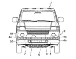
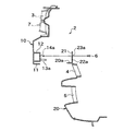
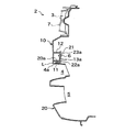
図1は、本発明に係るフロントバンパ構造が適用される車両の前部を示した正面図、図2は、アッパーバンパとロアバンパを示した分解斜視図,図3は、アッパーバンパとフロントバンパを組付けた状態のバンパと車両の前部を示した斜視図、図4は、アッパーバンパとロアバンパの中央部の分解断面図,図5はアッパーバンパとロアバンパを組付けた状態の断面図,図6は、フロントバンパの架橋部がある部分の断面図である。
Hereinafter, a front bumper structure according to the present invention will be described with reference to the drawings.
1 is a front view showing a front portion of a vehicle to which a front bumper structure according to the present invention is applied, FIG. 2 is an exploded perspective view showing an upper bumper and a lower bumper, and FIG. 3 is a view showing the upper bumper and the front bumper. FIG. 4 is an exploded cross-sectional view of the central portion of the upper bumper and the lower bumper, and FIG. 5 is a cross-sectional view of the upper bumper and the lower bumper assembled. 6 is a cross-sectional view of a portion where the bridging portion of the front bumper is present.
図1および図2に示した自動車1のフロントバンパ2には、空気流入口3〜5が上下に3箇所設けられている。そして、中間に位置する空気流入口4は幅方向に長く形成されている。
このフロントバンパ2は、図3に示したように、アッパーバンパ10とロアバンパ20とによって構成された2分割型のバンパで、空気流入口4は、ロアバンパ20の上部側中間部に所定の幅で設けられている。アッパーバンパ10とロアバンパ20は、空気流入口4の上縁4aおよび両側縁4b,該側縁から水平方向外方4cに向けて分割線Lを有している。
The
As shown in FIG. 3, the
そして、アッパーバンパ10の下縁には、図4に示すように、後方に向けてフランジ11が形成されている。また、アッパーバンパ10の後面には、該フランジ11の幅方向中央部直上に、後方に向けてボス部12が形成されている。そして、ボス部12には、車体後方へ突出するピン13aが一体に形成され、該ピン13aの直上には、ねじ孔14aが形成されている。
A
さらに、アッパーバンパ10の側部にも、図3に示すように、内方に向けてフランジ15が形成され、フランジ15には、該フランジの全幅に亘って、上方に向けてリブ16が形成されている。このリブ16は、雨天に車両を走行させたときに、泥水等が側部フランジ15まで跳ね上がった場合に、泥水等の流れをバンパ2の中央側まで伝わらないようにするための堰を成す。
Further, as shown in FIG. 3, a
また、アッパーバンパ10の裏面の左右には、図6に示すように、後方に向けて延出する架橋部17が上下方向に、一体成形により形成されている。この架橋部17の前面17aとアッパーバンパ10の裏面10bとには、隙間Sが形成されている。架橋部17の前面17aが、アッパーバンパ10の裏面10bと接触していないため、成形時にアッパーバンパ10の前面にひけが生じない。接触しているフロントグリル7の空気流入口3の下面10aに、ヒケが生じてもフロントグリル7で隠され、また、下縁フランジ11に、ヒケが生じても、見えない位置であるので、見栄えに影響がない。
Moreover, as shown in FIG. 6, the bridge |
そして、この架橋部17には、車体後方に突出するピン13bが形成され、該ピン13bの下方に、ねじ孔14bが形成されている。なお、この架橋部17は、アッパーバンパ10の空気流入口3と4間の補強をする。
The
一方、ロアバンパ20には、図4に示したように、空気流入口4の上部壁を形成する上部縁20aから上方に突出するフランジ21が形成され、該フランジ21には、アッパーバンパ10のボス部12のピン13a,13bを挿入するピン挿入孔22a,22bが形成され、さらに、その上方または下方には、ねじ挿通孔23a,23bが形成されている。
On the other hand, as shown in FIG. 4, the
このように形成されたアッパーバンパ10とロアバンパ20は、以下のようにして、互いに結合される。
まず、アッパーバンパ10のピン13a,13bを、ロアバンパ20のピン挿入孔22a,22bに挿入させながら、ロアバンパ20の空気流入口4を画成する上部縁20aの下面にアッパーバンパ10のフランジ11を当接させて、ロアバンパ20に対するアッパーバンパ10の位置決めを図る。
The
First, while inserting the
次いで、ロアバンパ20のねじ挿通孔23a,23bに、ねじ6を挿通し、このねじ6をアッパーバンパ10のねじ孔14a,14bに螺合させて、アッパーバンパ10とロアバンパ20とを互いに締結する。
Next, the
このようにしてアッパーバンパ10とロアバンパ20とが組み付けられたバンパ2には、図2に示したように、フロントグリル7等が取付けられ、そして、車体8にねじ等によって取付けられる。
As shown in FIG. 2, the
上記実施の形態によれば、アッパーバンパ10とロアバンパ20は、空気流入口4の上縁4aおよび両側縁4b,該側縁から水平方向外方4cに向けて分割線Lを有しているので、少なくとも空気流入口の縁部では、両バンパ10,20の分割部が目立たないことから、両バンパ10,20の少なくとも一方が変形しても、見栄えが悪くなることはない。アッパーバンパ10のピン13a,13bを、ロアバンパ20のピン挿入孔22a,22bに挿入させながら、ロアバンパ20の空気流入口4を画成する上部縁20aの下面にアッパーバンパ10のフランジ11を当接させているので、ロアバンパ20に対するアッパーバンパ10の位置決めを図ることができる。
また、アッパーバンパ10の裏面の左右には、後方に向けて延出する架橋部17が上下方向に、一体成形により形成されているので、アッパーバンパ10の空気流入口3と4間の補強をすることができる。
この架橋部17の前面17aとアッパーバンパ10の裏面10bとには、隙間Sが形成され、架橋部17の前面17aが、アッパーバンパ10の裏面10bと接触していないため、成形時にアッパーバンパ10の前面にひけが生じない。そして、接触しているフロントグリル7の空気流入口3の下面10aに、ヒケが生じてもフロントグリル7で隠され、また、下縁フランジ11に、ヒケが生じても、見えない位置であるので、見栄えに影響がない。
According to the above-described embodiment, the
Moreover, since the bridge | crosslinking
A gap S is formed between the
なお、上記実施の形態では、アッパーバンパ10とロアバンパ20との分割線を、空気流入口4の上縁部に沿って形成したが、空気流入口4の下縁部に沿って形成してもよい。この場合、空気流入口4部は、アッパーバンパ10側に設ける。等、その他本発明の要旨を変更しない範囲内で適宜変更して実施し得ることは言うまでもない。
In the above embodiment, the dividing line between the
1 自動車
2 フロントバンパ
3,4,5 空気流入口
6 ねじ
7 フロントグリル
8 車体
10 アッパーバンパ
10a 下面
10b 裏面
11 フランジ
12 ボス部
13a,13b ピン
14a,14b ねじ孔
15 フランジ
16 リブ
17 架橋部
20 ロアバンパ
20a 上縁部
21 フランジ
22a,22b ピン挿入孔
23a,23b ねじ挿通孔
L 分割線
DESCRIPTION OF SYMBOLS 1
Claims (2)
アッパーバンパとロアバンパの分割線を、前記空気流入口の上縁に沿って位置させ、前記アッパーバンパの裏面に、前記空気流入口の上縁と前記開口の下縁を繋いで補強する架橋部を一体に形成し、前記架橋部を前記アッパーバンパの裏面から間隙をもって配設し、前記架橋部は、フロントグリルで隠される前記フロントグリルの開口の下面と前記アッパーバンパの下縁に形成された後方に向かって延びるフランジに接続され、前記架橋部には、車体後方に突出するピンが形成され、前記ロアバンパに、前記ピンが挿入されるピン挿入孔を形成し、前記ピンを前記ピン挿入孔に挿入させることによって、前記アッパーバンパをロアバンパに位置決めさせるようにしたことを特徴とするフロントバンパ構造。 The upper bumper and the lower bumper are connected to each other, an air inlet that is long in the width direction is formed in the center of the front surface , and an opening of the front grill is disposed above the air inlet of the upper bumper. In the front bumper structure
The dividing line of the upper bumper and Roabanpa, are positioned along the air inlet of the upper edge, on the back surface of the upper bumper, the bridge portion which reinforces by connecting the lower edge of the upper edge and the opening of the air inlet The bridge portion is formed integrally with a gap from the back surface of the upper bumper, and the bridge portion is formed on the lower surface of the opening of the front grill concealed by the front grill and the lower edge of the upper bumper. A pin that protrudes toward the rear of the vehicle body is formed in the bridging portion, a pin insertion hole into which the pin is inserted is formed in the lower bumper, and the pin is used as the pin insertion hole. A front bumper structure in which the upper bumper is positioned on the lower bumper by being inserted .
Priority Applications (1)
| Application Number | Priority Date | Filing Date | Title |
|---|---|---|---|
| JP2004232973A JP4552182B2 (en) | 2004-08-10 | 2004-08-10 | Front bumper structure |
Applications Claiming Priority (1)
| Application Number | Priority Date | Filing Date | Title |
|---|---|---|---|
| JP2004232973A JP4552182B2 (en) | 2004-08-10 | 2004-08-10 | Front bumper structure |
Publications (2)
| Publication Number | Publication Date |
|---|---|
| JP2006051848A JP2006051848A (en) | 2006-02-23 |
| JP4552182B2 true JP4552182B2 (en) | 2010-09-29 |
Family
ID=36029598
Family Applications (1)
| Application Number | Title | Priority Date | Filing Date |
|---|---|---|---|
| JP2004232973A Expired - Fee Related JP4552182B2 (en) | 2004-08-10 | 2004-08-10 | Front bumper structure |
Country Status (1)
| Country | Link |
|---|---|
| JP (1) | JP4552182B2 (en) |
Families Citing this family (2)
| Publication number | Priority date | Publication date | Assignee | Title |
|---|---|---|---|---|
| JP5702706B2 (en) * | 2011-11-25 | 2015-04-15 | 本田技研工業株式会社 | Body front structure |
| JP6786561B2 (en) * | 2018-09-26 | 2020-11-18 | 本田技研工業株式会社 | Body front structure |
Family Cites Families (3)
| Publication number | Priority date | Publication date | Assignee | Title |
|---|---|---|---|---|
| JPH08258646A (en) * | 1995-03-27 | 1996-10-08 | Toyota Motor Corp | Automotive resin bumpers |
| JP3624551B2 (en) * | 1996-06-24 | 2005-03-02 | マツダ株式会社 | Front bumper structure of automobile |
| JP3912479B2 (en) * | 2001-01-22 | 2007-05-09 | スズキ株式会社 | Front grille structure |
-
2004
- 2004-08-10 JP JP2004232973A patent/JP4552182B2/en not_active Expired - Fee Related
Also Published As
| Publication number | Publication date |
|---|---|
| JP2006051848A (en) | 2006-02-23 |
Similar Documents
| Publication | Publication Date | Title |
|---|---|---|
| JP3912479B2 (en) | Front grille structure | |
| JP3920257B2 (en) | Side sill garnish mounting structure | |
| US20130026746A1 (en) | Vehicle body structure for automobile | |
| JP2015048024A (en) | vehicle | |
| JP2006088735A (en) | Front bumper structure of automobile | |
| JP4552182B2 (en) | Front bumper structure | |
| US20240416858A1 (en) | Vehicle grille structure | |
| JP5115289B2 (en) | Radiator grill for vehicles | |
| JP3619064B2 (en) | Automobile fender structure | |
| JP4753983B2 (en) | Side splash guard mounting structure | |
| CN104228728B (en) | rear bumper | |
| JP2008184001A (en) | Door trim structure for vehicle | |
| JP4858722B2 (en) | Vehicle lighting | |
| JP4266212B2 (en) | Vehicle front structure | |
| KR100304715B1 (en) | Air duct structure for instrument panel for motor vehicle | |
| JP2008265483A (en) | Car cowl structure | |
| JP2016132301A (en) | Inner fender | |
| JP4996576B2 (en) | Air conditioning grille part mounting structure | |
| JP6788936B2 (en) | Resin molded body for vehicles | |
| JP5407781B2 (en) | Front bumper grill structure | |
| JP4112301B2 (en) | Headrest insert and headrest | |
| JP4718958B2 (en) | Front bumper | |
| JP2008296845A (en) | Bumper mounting structure | |
| JP2001260944A (en) | Fender protector structure for vehicle | |
| JP2008280015A (en) | Rear side spoiler |
Legal Events
| Date | Code | Title | Description |
|---|---|---|---|
| A621 | Written request for application examination |
Free format text: JAPANESE INTERMEDIATE CODE: A621 Effective date: 20070711 |
|
| A131 | Notification of reasons for refusal |
Free format text: JAPANESE INTERMEDIATE CODE: A131 Effective date: 20091020 |
|
| A977 | Report on retrieval |
Free format text: JAPANESE INTERMEDIATE CODE: A971007 Effective date: 20091022 |
|
| A521 | Request for written amendment filed |
Free format text: JAPANESE INTERMEDIATE CODE: A523 Effective date: 20091216 |
|
| TRDD | Decision of grant or rejection written | ||
| A01 | Written decision to grant a patent or to grant a registration (utility model) |
Free format text: JAPANESE INTERMEDIATE CODE: A01 Effective date: 20100618 |
|
| A01 | Written decision to grant a patent or to grant a registration (utility model) |
Free format text: JAPANESE INTERMEDIATE CODE: A01 |
|
| A61 | First payment of annual fees (during grant procedure) |
Free format text: JAPANESE INTERMEDIATE CODE: A61 Effective date: 20100701 |
|
| FPAY | Renewal fee payment (event date is renewal date of database) |
Free format text: PAYMENT UNTIL: 20130723 Year of fee payment: 3 |
|
| R151 | Written notification of patent or utility model registration |
Ref document number: 4552182 Country of ref document: JP Free format text: JAPANESE INTERMEDIATE CODE: R151 |
|
| FPAY | Renewal fee payment (event date is renewal date of database) |
Free format text: PAYMENT UNTIL: 20130723 Year of fee payment: 3 |
|
| FPAY | Renewal fee payment (event date is renewal date of database) |
Free format text: PAYMENT UNTIL: 20130723 Year of fee payment: 3 |
|
| FPAY | Renewal fee payment (event date is renewal date of database) |
Free format text: PAYMENT UNTIL: 20140723 Year of fee payment: 4 |
|
| LAPS | Cancellation because of no payment of annual fees |


