JP4551392B2 - Front vision device for automobiles - Google Patents
Front vision device for automobiles Download PDFInfo
- Publication number
- JP4551392B2 JP4551392B2 JP2006501354A JP2006501354A JP4551392B2 JP 4551392 B2 JP4551392 B2 JP 4551392B2 JP 2006501354 A JP2006501354 A JP 2006501354A JP 2006501354 A JP2006501354 A JP 2006501354A JP 4551392 B2 JP4551392 B2 JP 4551392B2
- Authority
- JP
- Japan
- Prior art keywords
- mirror
- window
- vehicle
- configuration
- driver
- Prior art date
- Legal status (The legal status is an assumption and is not a legal conclusion. Google has not performed a legal analysis and makes no representation as to the accuracy of the status listed.)
- Expired - Fee Related
Links
Images


Classifications
-
- B—PERFORMING OPERATIONS; TRANSPORTING
- B60—VEHICLES IN GENERAL
- B60R—VEHICLES, VEHICLE FITTINGS, OR VEHICLE PARTS, NOT OTHERWISE PROVIDED FOR
- B60R1/00—Optical viewing arrangements; Real-time viewing arrangements for drivers or passengers using optical image capturing systems, e.g. cameras or video systems specially adapted for use in or on vehicles
- B60R1/10—Front-view mirror arrangements; Periscope arrangements, i.e. optical devices using combinations of mirrors, lenses, prisms or the like ; Other mirror arrangements giving a view from above or under the vehicle
-
- B—PERFORMING OPERATIONS; TRANSPORTING
- B60—VEHICLES IN GENERAL
- B60R—VEHICLES, VEHICLE FITTINGS, OR VEHICLE PARTS, NOT OTHERWISE PROVIDED FOR
- B60R1/00—Optical viewing arrangements; Real-time viewing arrangements for drivers or passengers using optical image capturing systems, e.g. cameras or video systems specially adapted for use in or on vehicles
- B60R1/02—Rear-view mirror arrangements
- B60R1/06—Rear-view mirror arrangements mounted on vehicle exterior
-
- G—PHYSICS
- G02—OPTICS
- G02B—OPTICAL ELEMENTS, SYSTEMS OR APPARATUS
- G02B5/00—Optical elements other than lenses
- G02B5/08—Mirrors
-
- G—PHYSICS
- G02—OPTICS
- G02B—OPTICAL ELEMENTS, SYSTEMS OR APPARATUS
- G02B5/00—Optical elements other than lenses
- G02B5/08—Mirrors
- G02B5/09—Multifaceted or polygonal mirrors, e.g. polygonal scanning mirrors; Fresnel mirrors
-
- G—PHYSICS
- G02—OPTICS
- G02B—OPTICAL ELEMENTS, SYSTEMS OR APPARATUS
- G02B5/00—Optical elements other than lenses
- G02B5/08—Mirrors
- G02B5/10—Mirrors with curved faces
Abstract
Description
本発明は、前方視認装置(forward viewing apparatus)に関し、特に自動車などの車両上で使用される前方視認装置に関する。 The present invention relates to a forward viewing apparatus, and more particularly to a forward viewing apparatus used on a vehicle such as an automobile.
自動車の運転者は、交通の流れの中で運転する際、常に2、3台先の車を運転すべきであると言われる。この表現は、運転者が、車両の方向の変化や、それよりも重要な速度の変化について、自分の車両の直前の車両のそのような変化を待つのではなく、自分の車両から2、3台先の車両を見て、その車両の変化に対応できるようにすべきであるという意味である。 Car drivers are said to always drive a few cars ahead when driving in traffic. This expression means that the driver does not wait for such a change in the vehicle immediately before his vehicle for a change in the direction of the vehicle or, more importantly, a change in speed, but a few This means that you should be able to look at the vehicle at the tip and respond to changes in that vehicle.
しかし、たとえばオーストラリアの都市の現在の交通状況では、2、3台先の車両を運転することがまずます困難になっている。というのは、運転者が自分の車両の直前の車両よりも前を見ることができないことが多いからである。多くの車両は現在、濃く色付けされたウィンドウを有し、それによって車両またはステーション・ワゴンの前方の車を見ることが困難または不可能になっている。さらに、窓を有さないか、または濃く色付けされた窓を有するか、または運転席が高すぎて前方の車両が見えない、多数のトラック、バン、特に四輪駆動の「レクリエーション・ビークル(RV)」が存在する。 However, for example, in the current traffic situation in Australian cities, it is increasingly difficult to drive a few vehicles ahead. This is because the driver often cannot see ahead of the vehicle in front of his vehicle. Many vehicles currently have a darkly colored window, which makes it difficult or impossible to see the vehicle in front of the vehicle or station wagon. In addition, many trucks, vans, especially four-wheel drive “recreational vehicles” (RVs) that have no windows, have dark colored windows, or have a driver's seat too high to see the vehicle ahead. ) ”.
前方視野ミラー用の機構を設け、運転者が、その車両の直前のそのような車両の周りを見渡せるようにする試みがなされている。米国特許第4,685,779号は、明細書の「発明の背景」節における問題の簡単な説明と1986年よりも前の先行技術の有用な概要を別として、一方の部材が車両のドアに取り付けられ、他方の部材が連結によって第1の本体部材に結合された2本体部材において3つのミラーを有する複雑な組合せ前方・後方視認ミラー・アセンブリを開示している。 Attempts have been made to provide a mechanism for the front-view mirror so that the driver can look around such a vehicle just before the vehicle. U.S. Pat.No. 4,685,779, apart from a brief description of the problem in the `` Background of the Invention '' section of the specification and a useful overview of prior art prior to 1986, one member is attached to the vehicle door, A complex combined forward / backward viewing mirror assembly is disclosed having three mirrors in a two body member, the other member coupled to the first body member by a connection.
米国特許第4,268,120号は、「死角」を無くすように車両の運転者に対する車両の両側に配置されるようになっている前方視野ミラー構成について説明している。米国特許第4,268,120号の図3は、透明カバーを通してハウジングに入射した光を車両の運転者に向ける2ミラー構成(two-mirror arrangement)を示している。 U.S. Pat. No. 4,268,120 describes a front-view mirror arrangement that is arranged on both sides of the vehicle relative to the vehicle driver so as to eliminate "dead spots". FIG. 3 of US Pat. No. 4,268,120 shows a two-mirror arrangement that directs light incident on the housing through a transparent cover to the vehicle driver.
米国特許第685,779号および米国特許第4,268,120号に例示されているように、概念的な前方視野ミラーが存在するにもかかわらず、現在の自動車は前方視野ミラーを備えていない。 As illustrated in US Pat. Nos. 6,857,779 and 4,268,120, despite the existence of a conceptual front field mirror, current automobiles do not include a front field mirror.
オーストラリアの保険会社であるNMRA Insuranceは、2002年10月31日に、車両の運転者席からの「車の後方」の視認性の測定結果である「World First Reversing Visibility Index」を発表した。試験された多くの車両は、車両の後方に大きなブラインド・スポットを有していた。このIndexに関する報道では、ブラインド・スポットを解消する1つの方法は、内部後部視野ミラー内に配置された小形LCD画面にリンクされた、後方を向いたビデオ・カメラを車両の後方に設置することであることが示された。しかし、このような構成のコストは、1,500ドル程度になることが示された。このような数字は、理想的には車両の各側に1つの2つのカメラと2つのスクリーンが必要になることを除いて、一般に前方視野構成にも当てはまる。したがって、コストが2倍になり、たいていの人には手が出ない。 NMRA Insurance, an Australian insurance company, announced the World First Reversing Visibility Index on October 31, 2002, which is a measurement of the visibility of the "rear of the car" from the driver's seat of the vehicle. Many vehicles tested had a large blind spot behind the vehicle. In this Index report, one way to eliminate blind spots is to install a rear-facing video camera linked to a small LCD screen located in the internal rear view mirror at the rear of the vehicle. It was shown that there is. However, the cost of such a configuration was shown to be around $ 1,500. Such numbers generally apply to the front vision configuration, except that ideally two cameras and two screens are required on each side of the vehicle. Therefore, the cost is doubled and most people are out of hand.
本発明の目的は、自動車用の改良された視野装置を提供することである。 The object of the present invention is to provide an improved field of view device for motor vehicles.
第1の局面において、本発明は、自動車用前方視野装置(forward view apparatus)であって、自動車の運転者が見ることのできる画像としてアセンブリの前方位置からの画像を提供する装置であり、第1の平面ミラー、および該装置中に固定され調整が不可能な第2の曲面ミラーを有する2ミラー構成を含む装置を提供する。
好ましくは、これらミラーの第1のミラーは調節可能である。 In a first aspect, the present invention provides a forward field of view device for a motor vehicle (forward view apparatus), an apparatus for providing an image from the front of the assembly as an image that can be the driver of the vehicle seen, the There is provided an apparatus comprising a two-mirror configuration having one plane mirror and a second curved mirror that is fixed in the apparatus and cannot be adjusted .
Preferably, the first mirror of these mirrors is adjustable.
本発明は、自動車用前方視野装置であって、自動車の運転者が見ることのできる画像としてアセンブリの前方位置からの画像を与える装置において、アセンブリの前方位置からの光がウィンドウを通過し、2ミラー構成によって反射され、視認ポータルを通じて自動車の運転者の目に入り、かつ視認ポータルが2ミラー構成の内方に配置されることを特徴とする装置も提供する。 The present invention is an automotive front vision device that provides an image from the front position of the assembly as an image that can be viewed by a motor vehicle driver, wherein light from the front position of the assembly passes through the window, and 2 There is also provided an apparatus characterized in that it is reflected by the mirror configuration and enters the eyes of the driver of the vehicle through the visual portal, and the visual portal is arranged inside the two-mirror configuration.
本発明は、自動車用前方視野装置であって、自動車の運転者が見ることのできる画像としてアセンブリの前方位置からの画像を与える装置において、閉位置と開位置との間を移動するようになっているシャッター手段があり、閉位置では、光が装置に到達するのが妨げられ、開位置では、光が装置に到達できることを特徴とする装置をさらに提供する。 The present invention is a forward vision device for an automobile that moves between a closed position and an open position in an apparatus that provides an image from the front position of the assembly as an image that can be viewed by a driver of the automobile. There is further provided an apparatus, characterized in that there is a shutter means, wherein light is prevented from reaching the apparatus in the closed position and light can reach the apparatus in the open position.
本発明は、自動車用前方視野装置であって、自動車の運転者が見ることのできる画像としてアセンブリの前方位置からの画像を与える装置において、自動車が前方に移動しているときに、水および/もしくは他の物質を除去し、かつ/または水および/もしくは他の物質がウィンドウに付着するのを防止する、ウィンドウを横切る空気流を生成する構成を特徴とする装置も提供する。 The present invention is a vehicle front vision device that provides an image from the front position of the assembly as an image that can be viewed by a vehicle driver when the vehicle is moving forward and water and / or Alternatively, an apparatus is also provided that features an arrangement that generates an air flow across the window that removes other materials and / or prevents water and / or other materials from adhering to the window.
本発明の好ましい態様について、以下に添付の図面を参照して説明する。 Preferred embodiments of the present invention will be described below with reference to the accompanying drawings.
各図面は、自動車(図示せず)上の、従来の後方視野ミラーが配置される位置に配置されるようになっている本発明による右側前方視野装置10を示している。ただし、左側位置に同じアセンブリまたは(車両の前方から後方への線を中心とする)鏡像アセンブリを設けてよいことを理解しなければならない。ミラー・アセンブリは左ハンドル車両にも右ハンドル車両にも適していることを理解すべきである。
Each drawing shows a right
各図面において、右ハンドル前方視野装置10は、一般に後方視野ウィング・ミラー用の先行技術のハウジングと同様であってよいハウジング12を含んでおり、後方視野ミラー構成用のこのようなハウジングは通常、プラスチック材料で形成され、後方視野ミラー14が配置されたカップ形状を有している。
In each drawing, a right handle
本明細書全体にわたって、「前方」という用語は、本発明のアセンブリを取り付けることのできる車両の前方と同じ意味であり、「後方」という用語は、このような車両の後方と同じ意味を有することを理解されたい。 Throughout this specification, the term “front” has the same meaning as the front of the vehicle to which the assembly of the present invention can be attached, and the term “rear” has the same meaning as the rear of such a vehicle. I want you to understand.
好ましくは、ハウジング12は、右ハンドル車両(不図示)のボディの、運転者のドアの直前に取り付けられるようになっているが、任意の適切な位置に配置してよい。ハウジング12は、好ましくは車両の運転者が車両の後方を見るときに使用するようになっている従来の後方視野ミラーである第1のミラーなど14をその後部に含んでいる。もちろん、このミラー内の画像は反転される。
Preferably, the
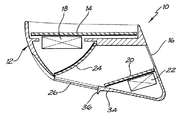
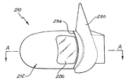
次に特に図1〜4を参照して、図1の断面が図4の線A-Aに沿った断面であることに留意されたい。この態様では、ミラー構成10は好ましくは、ピボット運動分離点上に取り付けられている。構成10は、車両から間隔を置いて配置された別個の自給式ユニットであり、車両の動きによって生成される空気流が車とこの構成との間を通過させる。
With particular reference now to FIGS. 1-4, it should be noted that the cross section of FIG. 1 is a cross section taken along line AA of FIG. In this embodiment, the
本発明の第1の態様には、運転者が、運転中の車両の直前の車両を越えて、運転者の車両の直前の車両の前方にある車両を見たいときに前方視野画像を見ることのできる前方視認領域16がある。好ましくは、ポータル16は、開口部であり、この開口部を通して、運転者は車両の前方からアセンブリ10を通過した光を見ることができる。
In the first aspect of the present invention, the driver views the front view image when he / she wants to see the vehicle in front of the vehicle immediately before the driver's vehicle beyond the vehicle immediately before the vehicle being driven. There is a
この態様では、前方視認ポータル16は、構成10のハウジング12の側面に配置されており、視線は、後方視野ミラー14の後方および構成10のピボット運動取付け点(図示せず)の前方を通る。
In this embodiment, the
図1では、後方視野ミラー14は、モータ18によって従来の方法で調整される。図1から4の態様の前方視野ミラー構成は第1のミラー20を含んでいる。第1のミラー20は好ましくは、平面状であり、さらに好ましくは、手動でまたはずれた位置にあってよいモータ22を用いることによって調整可能である。ハウジング12内に第2のミラー24が配置されている。第2のミラー24は好ましくは、固定され、すなわち調整不能であり、さらに好ましくは湾曲している。より好ましくは、ミラー24は、非球面、球面、実質的に球面、放物線状、または準放物線状である。しかし、ミラー24の湾曲は任意の形をとってよい。たとえば、ミラー24が凸状の下部と実質的に平面状の上部とを有しても、そのような構成が側方構成であってもよい。
In FIG. 1, the
光が前方視野ミラー構成に到達するようにハウジング12上にウィンドウ26が設けられている。ウィンドウ26は、透明であり、好ましくは密封された透明なウィンドウであり、好ましくはガラスまたはアクリル材料で形成される。ウィンドウ26の形状は好ましくは、ハウジング12の前面の湾曲に従うが、前方視野を最大にし、ウィンドウの表面から水を弾くのを助けるために、ウィンドウ26は好ましくは、外側に湾曲するかまたは凸状であり、さらに好ましくは、ハウジング12の外周の方へ配置される。ウィンドウ26に水および異物が付着しないようにするのを助けるために関連出願に記載されているベンチュリ・アンド・ボルテックス構成28を含めてもよい。
A
構成10が取り付けられた車両の前方からの光は最初、固定ミラー24に当たり、調整可能なミラー20に反射され、再び前方視認ポータル16を通して車両の運転者の目に反射される。図1〜4の態様では、構成10は好ましくは、運転者のウィンドウ、または車両の、運転者のウィンドウとは反対側の乗員のウィンドウを通して視認するためのみに用いられる。
The light from the front of the vehicle to which the
図5〜7には、本発明の第2の態様が示されている。図5の断面は、図6の線A-Aに沿った断面である。この態様では、前方視野アセンブリ110は、好ましくは、構成が取り付けられる車両のボディ(三角形のドア/ウィンドウ取付け板が130で示されている)と一体化されたハウジング(図1〜4のハウジング12と概ね同様)を有している。したがって、図1〜4に関して説明した状況とは異なり、構成110と車両との間を空気が通過することはできない。
5 to 7 show a second embodiment of the present invention. The cross section in FIG. 5 is a cross section along the line AA in FIG. In this embodiment, the
構成110は、モータ118によって従来の方法で調整可能な従来の後方視野ミラー114を有している。前方視野ポータル116はハウジング112の側部に配置されている。ハウジング112に第1の内方ミラー120が配置されているが、内方ミラー120は好ましくは、図5に示されているようにハウジングを越えて延びる。第1のミラー120は好ましくは平面状であり、さらに好ましくは、手動でまたはモータ122を用いることによって調整可能である。
ハウジング112内に第2のミラー124が配置されている。第2のミラー124は好ましくは、固定され、すなわち調整不能であり、さらに好ましくは湾曲している。より好ましくは、ミラー124は、非球面、球面、実質的に球面、放物線状、または準放物線状である。しかし、ミラー124の湾曲は任意の形をとってよい。たとえば、ミラー124が凸状の下部と実質的に平面状の上部とを有しても、そのような構成が側方構成であってもよい。
A
光が前方視野ミラー構成に到達するようにハウジング112上にウィンドウ126が設けられている。ウィンドウ126は、透明であり、好ましくは密封された透明なウィンドウであり、好ましくはガラスまたはアクリル材料で形成される。ウィンドウ126は、この態様では、図6に示されているように、ハウジング112上のより中央よりに配置されている。このため、ハウジング112上に周辺インジケータ(図示せず)を収容することができ、かつモータ122をより中央よりに取り付けることができる。
A
ウィンドウ126の形状は好ましくは、ハウジング112の前面の湾曲に従うが、前方視野を最大にし、ウィンドウの表面から水を弾くのを助けるために、ウィンドウ126は好ましくは、外側に湾曲するかまたは凸状であり、さらに好ましくは、ハウジング112の外周の方へ配置される。ウィンドウ126に水および異物が付着しないようにするのを助けるために、図1〜4に関して説明したようなベンチュリ・アンド・ボルテックス構成128を含めてもよい。
The shape of the
構成110が取り付けられた車両の前方からの光は最初、固定ミラー124に当たり、調整可能なミラー120に反射され、再び前方視認ポータルまたは領域116を通して車両の運転者の目に反射される。図5〜7の態様では、構成110は好ましくは、運転者のウィンドウ、または車両の、運転者のウィンドウとは反対側の乗員のウィンドウを通して視認するためのみに用いられる。
Light from the front of the vehicle to which the
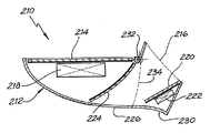
図8〜10には、本発明の第3の態様が示されている。図8の断面は、図9の線A-Aに沿った断面である。この態様では、前方視野アセンブリ210は、図5〜7の態様と同様に、構成が取り付けられる車両のボディ(三角形のドア/ウィンドウ取付け板が230で示されている)と一体化されたハウジング(図1〜4のハウジング12と概ね同様)を有している。したがって、この場合も、図1〜4に関して説明した状況とは異なり、構成210と車両との間を空気が通過することはできない。
8 to 10 show a third embodiment of the present invention. The cross section in FIG. 8 is a cross section along the line AA in FIG. In this embodiment, the
構成210は、好ましくはモータ218によって従来のように調整可能である従来の後方視野ミラー214を有している。ハウジング212内のミラー214の内方に前方視野ポータル216が配置されている。ドア・ウィンドウ取付け板またはブラケット230内に第1の内方ミラー220が配置されている(図8)。第1のミラー220は好ましくは平面状であり、さらに好ましくは、手動でまたはモータ222を用いることによって調整可能である。ミラー220およびモータ222の後部のピボット点232は、構成210が、衝撃が与えられたときまたは駐車時に、車両のボディの、取付け板230の後方に倒れるのを可能にする。構成210のハウジング212は、ミラー220の外方の分離線234に沿って取付け板230から分離される。ウィンドウ上の張出しフランジは、ハウジング212がその動作位置に戻ったときに密閉される埋め込みOリング(不図示)に係合するようになっている。ピボット点232の周りのハウジング212の移動は、手動で行うことも、モータなど(不図示)を用いて行うことができる。
図8〜10の態様における視認ポータルは、他の態様とは異なり車両のウィンドウではなく取付け板230、すなわち、ドアを通した視認を容易にする。
The visual portal in the embodiment of FIGS. 8-10 facilitates visual recognition through the mounting
ハウジング212内に第2のミラー224が配置されている。第2のミラー224は好ましくは、固定され、すなわち調整不能であり、さらに好ましくは湾曲している。より好ましくは、ミラー224は、非球面、球面、実質的に球面、放物線状、または準放物線状である。しかし、ミラー224の湾曲は任意の形をとってよい。たとえば、ミラー224が凸状の下部と実質的に平面状の上部とを有しても、そのような構成が側方構成であってもよい。
A
光が前方視野ミラー構成に到達するようにハウジング212上にウィンドウ226が設けられている。ウィンドウ226は、透明であり、好ましくは密封された透明なウィンドウであり、好ましくはガラスまたはアクリル材料で形成される。ウィンドウ226の形状は好ましくは、ハウジング212の前面の湾曲に従うが、前方視野を最大にし、ウィンドウの表面から水を弾くのを助けるために、ウィンドウ226は好ましくは、外側に湾曲するかまたは凸状であり、さらに好ましくは、ハウジング212の内周の方へ配置される。ウィンドウ226に水および異物が付着しないようにするのを助けるために、関連出願に記載されたベンチュリ・アンド・ボルテックス構成を含めてもよい。
A
構成210が取り付けられた車両の前方からの光は最初、固定ミラー224に当たり、調整可能なミラー220に反射され、再び前方視認ポータル216を通して車両の運転者の目に反射される。上述のように、視認ポータル226は好ましくは、取付け板230内に配置されている。このような構成は、車両内から前方視野ミラー構成210を視認する方法を容易にする。この特徴の利点は2つある。第1に、運転者が構成210を見たときに後方視野ミラー214と前方視野ミラー220との間に明確な境界が形成される。第2に、ポータル216が構成210の内側と車両の内側の両方と連通しているため、ミラー220および224が曇る可能性は低い。というのは、構成の内側が車両内側の周囲温度またはそれに近い温度に維持され、したがって、ミラーが清掃されるかまたは曇るのが防止されるからである。
Light from the front of the vehicle to which the
後方視野ミラー・モータ218の取付けは、構成210の中央に対して行っても、従来の後方視野ミラーと同様に行ってもよい。調整可能なミラー220および関連するモータ222が車両のドアの取付け板230内に配置され、いくらかさらに前方に配置されているため、特に運転者の側からの視認が容易に向上する。ウィング・ミラー(構成210のハウジング212)の実際のサイズは一般に従来のウィング・ミラー以下であると考えられる。前述の周辺インジケータを、修正を最小限に抑えつつハウジング212内に収容することができる。インジケータが必要でない場合、ミラー224を、図8に示されている位置から外方に移動させることができ、それによって視野をわずかに向上させるのが容易になる。運転者側のポータルと乗員側のポータル(216および不図示)はどちらも、サイドウィンドウを通すことなく容易に見ることができる。
The rear
ミラー20、120、220、24、124、および224の構成に関するかぎり、主要な問題は、左右の視認ポータル16、116、216を通した視認性に関するものであった。ミラー20/120/220および関連する24/214/224を前方に移動させる(これは、構成210のようにこれらの構成部材をドアに組み込むとより容易に行うことができる)ことによって、ミラー20/120/220の角度を車両に対して概ね直角に設定することができる。好ましくは、ミラー20/120/220は後方に約5度傾けられ、ミラー24/124/224は車両に対して約50度から約60度の角度に設定される。ミラー24/124/224が非球面でない場合、車両のボンネットの側面に沿った、約200m前方までの、車両の前輪の視野を、乗員側で大幅に向上させることができる。運転者側では、ミラー20/120/220を約10度回転させ、かつミラー20/120/220を後方に約5度傾けることによって、同様の結果が得られる。
As far as the configuration of the
ミラー24/124/224として使用される放物線状のミラーは満足行くものではないことが分かった。なぜなら、このミラーの曲率が大き過ぎ、その結果左右に与えられる周辺視野が多すぎると考えられためであった。形状が放物線状ミラーより平坦である非球面ミラーは、車両の前輪の距離と位置の両方に対処するため、より望ましいと考えられる。
It has been found that the parabolic mirror used as
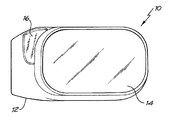
次に、ウィンドウ26、126、226について説明すると、図11は、このようなウィンドウの好ましい形状を示している。図示のウィンドウ26は、右ハンドル車両用の運転者側の構成10用のウィンドウの一例であり、このような車両の乗員側には鏡像を使用してよい。ウィンドウは226として示されているが、ウィンドウ26または126であってもよい。すべての3つの態様において、ウィンドウ26/126/226は好ましくは、水の保持量を最小限に抑えるためにウィング・ミラー構成の通常の形状に従うように湾曲しているかまたは凸状になっている。視認ガラスまたはアクリル・ウィンドウ26/126/226は好ましくは、密閉され気密状態であり、すなわち、水、異物などを構成10/110/210の内側に入れない。構成10/110/210の位置および角度は、水および道路のほこりが車両のフロントガラスからそれ、視認ウィンドウ26/126/226の前面を横切ることを意味している。これに対処し、ウィンドウ26/126/226を通した視野を良好にするために、ウィンドウ26の内方に凹状表面部34(図1)が設けられている。表面部34は、ウィンドウ26と表面領域34との間に配置された突起またはウィング36と一緒に、水、異物などを収集して分散させるシステムを構成している。ウィンドウ26の表面に当たったあらゆる水、道路のほこりなどは、前述の関連出願に記載されたベンチュリ・ボルテックス28によって横方向にウィンドウ26を横切って移動する。部材34および36について図1から4の態様に関して説明したが、これらを図5〜7および8〜10の態様にも同様に適用できることを理解されたい。
Next, the
上述のように、車両の左側にも同様のユニットを設け(右ハンドル車両の場合)、車両の左側に沿って前方を見ることができる。好ましくは、両方のアセンブリ10、110、210が、運転者に近い都合の良い位置から動作させることのできる、電気モータによるミラー調整装置を有する。または、調整を手動で行うことができる。このような代替態様は、手動調整手段を運転者/乗員の手の届く範囲内に配置することのできる構成220に特に適している。
As described above, a similar unit is provided on the left side of the vehicle (in the case of a right-hand drive vehicle), and the front can be seen along the left side of the vehicle. Preferably, both
本発明の前述の3つの態様のうちの1つに関して説明した特徴は、他の2つの態様に関係しているとみなすべきである。 Features described with respect to one of the three previous aspects of the invention should be considered as related to the other two aspects.
図3に関しては、内部ミラー・サイズを水平方向に約20mm大きくすることによって、運転者の様々な体格に対して調整可能なミラーを調整するためのモータは必要なくなる。このことは、ミラーを1つの位置に固定できることを意味する。右ハンドルか車両から左ハンドル車両に変更するときに必要になる唯一の移動は手動で実現することができ、これは工場で行うことができる。 With respect to FIG. 3, by increasing the internal mirror size by about 20 mm in the horizontal direction, there is no need for a motor to adjust the adjustable mirror for the various physiques of the driver. This means that the mirror can be fixed in one position. The only movement required when changing from a right-hand drive or vehicle to a left-hand drive vehicle can be accomplished manually, and this can be done at the factory.
前方視野アセンブリを運転者側のウィンドウを通さずに車両の内側から視認すると、判別が極めて容易になり、ユーザの使い勝手が向上する。これはさらに、内方および外方のミラーを車両内から加熱できることを意味する。このため、アセンブリ・ハウジング内の定められた加熱は不要になる。 When the front view assembly is viewed from the inside of the vehicle without passing through the driver's side window, the determination becomes extremely easy and the usability of the user is improved. This further means that the inner and outer mirrors can be heated from within the vehicle. This eliminates the need for defined heating within the assembly housing.
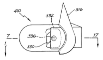
図12〜17は、本発明による前方視野装置の他の態様を示している。装置310は、参照番号10、110、および210によって前述の各図に示されている種類の装置である。装置310は、運転者のドアの直前で右ハンドル車両(不図示)のボディに取り付けられるようにすることができるが、任意の適切な位置に配置することができるハウジング312を有している。図12〜14では、ハウジング312は、使用時に車両の車体のラインに沿って配置され、車両の乗員区画の内側に前方視野視認ポータル318を構成することのできるビナクル316を含んでいる。もちろん、この視認ポータルは、車両の運転者が好都合に視認できる任意の場所に配置することができる。
12-17 show another embodiment of the front vision device according to the present invention.
次に特に図12〜14を参照して、図14の断面が図13の線14-14に沿った断面であることに留意されたい。この態様では、ミラー構成10は好ましくは、ピボット運動分離点320(図14)上に取り付けられる。図14の破線は、ハウジング312が点320の周りをピボット運動するときにハウジング312の外側部分が残りの部分から分離する「分離」線である。
With particular reference now to FIGS. 12-14, note that the cross section of FIG. 14 is a cross section taken along line 14-14 of FIG. In this embodiment, the
図12〜14の態様では、前方視認ポータル318は、運転者が、運転中の車両の直前の車両を越えて、運転者の車両の直前の車両の前方にある車両を見たいときに前方視野画像を見ることを可能にする。好ましくは、ポータル318は、開口部であり、この開口部を通して、運転者は車両の前方からアセンブリ310を通過した光を見ることができる。
In the embodiment of FIGS. 12-14, the
この態様では、前方視認ポータル318は、構成310のハウジング312の側面に配置されており、視線は、後方視野ミラー314の一方の側および構成310のピボット運動取付け点320の前方を通る。
In this embodiment, the
図12では、後方視野ミラー314は、モータ322によって従来の方法で調整される。図12から14の態様の前方視野ミラー構成310は第1のミラー324を含んでいる。第1のミラー324は好ましくは、平面状であり、さらに好ましくは、手動でまたはずれた位置にあってよいモータ326を用いることによって調整可能である。ハウジング312内に第2のミラー328が配置されている。第2のミラー328は好ましくは、固定され、すなわち調整不能であり、さらに好ましくは湾曲している。より好ましくは、ミラー328は、非球面、球面、実質的に球面、放物線状、または準放物線状である。しかし、ミラー328の湾曲は任意の形をとってよい。たとえば、ミラー328が凸状の下部と実質的に平面状の上部とを有しても、そのような構成が側方構成であってもよい。
In FIG. 12, the
光が前方視野ミラー構成に到達するようにハウジング312上にウィンドウ330が設けられている。ウィンドウ330は、透明であり、好ましくは密封された透明なウィンドウであり、好ましくはガラスまたはアクリル材料で形成される。ウィンドウ30の形状は好ましくは、ハウジング312の前面の湾曲に従うが、前方視野を最大にし、ウィンドウの表面から水を弾くのを助けるために、ウィンドウ330は好ましくは、外側に湾曲するかまたは凸状であり、さらに好ましくは、ハウジング312の外周の方へ配置される。
A
構成310が取り付けられた車両の前方からの光は最初、固定ミラー328に当たり、調整可能なミラー324に反射され、再び前方視認ポータル318を通して車両の運転者の目に反射される。図12〜14の態様では、構成310は好ましくは、運転者のウィンドウ、または車両の、運転者のウィンドウとは反対側の乗員のウィンドウを通して視認するためのみに用いられる。
Light from the front of the vehicle to which the
全体的に図12〜14の態様の方針に沿ったすでに提案されている前方視野構成は、運転者の視認性を向上させる助けになることが分かっているが、いくつかの問題が起こっている。これらの問題は、ユーザの使い勝手、運転者の個性、不信感、アセンブリを清浄に保つ問題、アセンブリのぎらつきおよび損傷に関する問題のような局面に関する問題である。たとえば、運転者がミラー・アセンブリを見たときに、どのミラーを見ているのか、すなわち、後方視野ミラーを見ているのかそれとも前方視野ミラーを見ているのか混乱する可能性がある。さらに、ポータル318を通して前方視野画像が絶えず見えるようにすると、運転手が注意散漫になる恐れがある。さらに、運転者は、対向車の光が前方視野装置を通して自分の目に反射されることによって眩惑される恐れもある。最後に、ウィンドウ30の前面(外面)が、道路のごみなどが蓄積することによって不透明になり、前方視野画像の画質が低下するか、場合によっては蓄積が継続する場合に、装置が無用になる恐れもある。ウィンド・ブレーカや、ボルテックス・チャネルや、小形フロントガラス・ワイパーや、ウォータ・ジェットなしにウィンドウ330を清浄に維持するのは依然として困難である。
Although the previously proposed forward vision configuration generally in line with the policy of the embodiment of FIGS. 12-14 has been found to help improve driver visibility, several problems are occurring . These problems are related to aspects such as user usability, driver personality, distrust, problems keeping the assembly clean, glare and damage to the assembly. For example, when a driver looks at a mirror assembly, it can be confusing which mirror he is looking at, i.e. he is looking at a rear-view mirror or a front-view mirror. Furthermore, if the front view image is continuously visible through the portal 318, the driver may be distracted. Furthermore, the driver may be dazzled by the light of the oncoming vehicle being reflected in his / her eyes through the front vision device. Finally, the front surface (outer surface) of the window 30 becomes opaque due to accumulation of road debris and the like, and the device becomes useless when the image quality of the front-view image is degraded or in some cases the accumulation continues. There is also a fear. It is still difficult to keep the
これらに対処するために、図12〜14の態様は、好ましくはウィンドウ330を横切って滑り、ウィンドウ330に入射する光を遮断するようになっているシャッター332を含んでいる。モータ334は、シャッター332を作動させ、開位置と閉位置の間を移動させるようになっている。モータ334は、概ねモータ322および326と同様である。
To address these, the embodiment of FIGS. 12-14 includes a
シャッター332は、ミラー・ハウジング312の形状に応じてトラック(図示せず)上を滑っても、ピボット運動させてもよい。ウィンドウ330を横切る動きは、好ましくはシャッター332に成形された歯車(図示せず)に噛み合う電気モータ334を用いることによって実現することができる。または、歯車付きモータが、極性が反転するときに延び引き込むことのできるはさみ(不図示)を動作させることができる。
The
シャッター332は、プラスチック材料または他の任意の適切な軽量材料で製造することができ、閉位置では、ごみ、ほこり、雨などが入らないようにウィンドウ332を密封する。シャッター332を開閉すると、その先端に取り付けることのできるフェルトまたはゴムのワイパー(図示せず)がウィンドウを横切って移動し、ほこり、雨水などを除去する。
The
シャッター332は、内方に収納され、すなわち、シャッターはウィンドウ330を横切って移動し、車両のドア空洞部またはハウジング312の取付けビナクル316内に配置される。これは、ミラー・アセンブリ310の非対称形状に対処するものである。
The
通常の運転条件では、左右両方のアセンブリ310のシャッター332が閉じたままであり、前述の混乱、注意散漫、または眩惑が解消される。さらに、道路のごみ、石、雨などはすべて、シャッター332によってそらされる。運転者は、道路状態、運転者の好みなどに応じて、前方視野ミラー機能をいつ使用するかを選択することができる。
Under normal operating conditions, the
右ハンドル車両の場合、左または右アセンブリのシャッター332を作動させるには、たとえば、方向指示器に使用されているのと同様なインジケータ・ストークを動かすことによって切換え機構(不図示)をトリガする。これは、方向を示す指示器を作動させる前に行うことができ、かつ従来の指示器に用いられているのと同じ形式で作用することができ、すなわち、ストークを持上げると、左アセンブリ310のシャッター332が開き、ストークを下に動かすと右アセンブリ310のシャッター332が作動する。
In the case of a right-hand drive vehicle, actuating the
ストーク、ダッシュボード、または他の場所上のオーバライド・ボタン(図示せず)によって一方または両方シャッター332を必要に応じて常に開けておくことも、リレー・スイッチなどの時間遅延機能を設けて、所定の時間、たとえば1分後にシャッター332を閉じることもできる。
One or both
図15〜17は、前方視野ミラー・アセンブリが410として指定された本発明の他の態様を示している。図12〜14に用いられると共に図15〜17にも用いられているすべての参照番号は、同じ部材を示している。部材324、326、および328は図15〜17には示されておらず、図17の断面は図16の線17-17に沿った断面である。
FIGS. 15-17 illustrate another embodiment of the invention in which the front field mirror assembly is designated as 410. FIG. All reference numbers used in FIGS. 12-14 and in FIGS. 15-17 indicate the same elements.
この態様では、図12〜14のミラー構成がビデオ・カメラとカメラ336によって生成された画像を示す画面338とで置き換えられている。カメラ336は前方を向くように位置しており、画面338(図示せず)に接続される回路など(図示せず)は従来のものである。画面338は好ましくは、LCD画面であってよく、ポータル318を通して見えるように示されていないが、ポータル18を横切って配置してよい。カメラ/画面構成336/338は単色または白黒であってよい。
In this embodiment, the mirror configuration of FIGS. 12-14 has been replaced with a video camera and a screen 338 showing an image generated by
あらゆる点で、シャッター332は、図12〜14に関して説明したように動作する。
In all respects, the
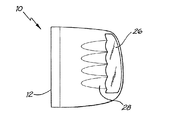
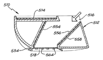
図18〜26には、本発明の他の態様が示されている。後方視野アセンブリ510はハウジング512を有している。ハウジング512の前面にウィンドウ518が配置されている。ウィンドウ518は、米国特許第4,268,120号の透明パネル8と概ね同様であってよく、アセンブリ510を取り付けることのできる車両の前方からの光をアセンブリ510の内部に送る。ウィンドウ518は、ハウジング512の前面に対して隆起していても、前面と同一平面を形成しても、前面に対してくぼんでいてもよい。窓518は前面に対してくぼんでおり、本明細書で後述する空気流生成手段と協働することが好ましい。ウィンドウは、ガラス、プラスチック材料、または透明または実質的に透明な任意の適切な材料で形成することができる。
18 to 26 show another embodiment of the present invention. The
ハウジング512の前面側および(使用時の)外側には、ウィンドウ518の前面を横切って空気を送る手段が配置されている。この空気流については以下に図18に関して詳しく説明するが、この手段は、ハウジング512の後部の(使用時の)内側に溝520を含んでいる。これらの溝は、ハウジング512の外側に向かって、リブ522および538の高さが高くなっていく結果として深さが深くなっていく。図18および19を見ると、溝520が隔壁524で終わり、かつ隔壁524の孔526が溝520とウィンドウ518との連通を可能にしていることが分かる。
On the front side of the
図18および19は、ハウジング512の外側が、溝520と概ね同様であり、リブ530によって形成され、隔壁532で終わる溝528を備え、隔壁532を通じて孔534が溝528とウィンドウ518との連通を可能にしていることを示している。
18 and 19, the outside of the
図18には、ハウジング512の前面側のベースに配置された他の溝536も示されている。溝536は、リブ538によって形成され、(以下に説明するように)空気をウィンドウ540内に送る。より小さな斜めの溝542、544、546が孔548、550、552(図18および19)を通して空気を送る。
FIG. 18 also shows another
次に図19を参照すると、ハウジング512内に配置された第1の前方視野ミラー554がある。ミラー554は、好ましくはハウジング512内に固定されるが、ミラー554が手動の手段、電気モータ、または他の任意の手段によって移動可能であることを理解されたい。ハウジング512内に第2の前方視野ミラー556も配置されている。ミラー556は好ましくは、ハウジング512内のミラー556、558の後方に配置された電気モータによって移動調整可能になっているが、このようなモータおよびそれに関連するケーブルおよびスイッチは示されていない。このようなモータを使用する場合、モータは、後方視野ミラーを調整するのに用いられる従来の構成と実質的に同様であってよい。もちろん、他の任意の調整形態を用いてよい。
Referring now to FIG. 19, there is a first
図21は、図19のミラー・アセンブリの好ましい傾斜構成を示している。560は、右ハンドル車両の側面であり、562はミラー・アセンブリ510の後部のラインである。ミラー556とライン562との間の角度が40度であり、ミラー554とライン562との間の角度が55度であることが分かる。もちろん、これらの角度は例示的なものに過ぎず、ミラー556が角度40度を使用する場合、この角度は、使用時に少なくともわずかに調整しなければならなる可能性が高い。ミラー554とミラー556との間の例示的な距離は50mmである。
FIG. 21 shows a preferred tilting configuration of the mirror assembly of FIG. 560 is the side of the right-hand drive vehicle, and 562 is the rear line of the
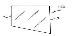
図22および23はそれぞれ、好ましい形状を有するミラー554および556の平面図を示している。ミラー556は、図21にも示されている側面CおよびDと一緒に示されている。これらの側面は好ましくは、長さがそれぞれ50mmおよび67mmであり、頂部および底部の長さは好ましくは、それぞれ90mmおよび95mmである。ミラー554は、図21にも示されている側面EおよびFと一緒に示されている。これらの側面の長さは好ましくは、それぞれ50mmおよび70mmであり、頂部および底部の長さは好ましくは、それぞれ80mmおよび87mmである。もちろん、すべての角度および寸法は例示的なものに過ぎず、変更することができる。
22 and 23 show plan views of
使用時には、運転者は、自分の車両の直前の車両の先を見たい場合、図19および21の矢印の方向に孔516(図19)を覗く。図19を見ると分かるように、特にミラー556、すなわち「画像取込み」ミラーは、車両の側面のかなり外方に配置され、したがって、2台前のこのような車両からの画像を受け取ることができる。前方に2台先の車両からの光は、ウィンドウ518を通過し、ミラー556からミラー554に反射され、次いでミラー554から孔514を通して運転者の芽に反射される。
In use, the driver looks into the hole 516 (FIG. 19) in the direction of the arrow in FIGS. 19 and 21 when he wants to see the tip of the vehicle immediately before his vehicle. As can be seen in FIG. 19, in particular the
前述のように、同様のユニットを(右ハンドル車両の場合に)車両の左側に配置し、車両の左側に沿って前方を見ることができる。好ましくは、どちらのアセンブリ510も、運転者に近い好都合な位置から動作させることのできる電気モータによってミラー556を調整することができる。
As mentioned above, a similar unit can be placed on the left side of the vehicle (in the case of a right-hand drive vehicle) and look forward along the left side of the vehicle. Preferably, both
ウィンドウ518が汚れ、運転者の見る画像が極端に不明瞭になることがある。本発明は、このような難点を解消する改良された構成を提供することを追及している。次に、図18および20、特に図18に戻ると、ハウジング512の前面のウィンドウ518のベースに配置され、溝536、542、544、および546と連通する孔564を見ることができる。
The
左右および上向きに延びる図18内の小さな矢印は、車両(図示せず)が前方に移動しているときの空気流の方向を示している。結果的にアセンブリ510が空気中を前方に移動するため、このような空気流が生成する。図18に示されているように、溝520/リブ522にぶつかった空気は、溝520によって孔526を通過させられ、ウィンドウ518を右から左に横切る。図18に示されているように、溝538、542、544、および546にぶつかった空気は、孔564を通ってウィンドウ518の外面を横切りベースから頂部へ送られる。
The small arrows in FIG. 18 that extend from side to side and upward indicate the direction of air flow when the vehicle (not shown) is moving forward. As a result, such an air flow is generated as the
特に、溝528に沿った空気の流れ、接線方向または概ね接線方向とみなすことができ、ベンチュリ効果を含む流れ。この場合、空気などの流体における圧力差は、その流体の流れがある領域または位置を越えることによって生じ、その領域または位置の所の圧力を低下させる。より高い圧力の流体が、その領域または位置を通じて流れに導入される。
In particular, a flow of air along the
図18および20の態様では、流体はもちろん空気であり、孔534はベンチュリであり、より低い圧力によって空気が図18の右から左に引き込まれる。ベンチュリ534を通して引き込まれた空気の少なくとも一部は、ウィンドウ518の外面を横切って送られる空気であってよい。孔526から出て孔534の方向に向かう空気の流れは、少なくとも部分的に誘発されるか否かにかかわらず、図18の左から右に流れるエア・カーテンであって、雨、霧、みぞれ、雪などよって蓄積される水ならびにウィンドウ518に付着し、車両の運転者が見る前方視野を少なくとも部分的に不明瞭にする空気および/または水によって運ばれる汚染物質を除去する働きをするエア・カーテンを生成させることができる。この構成を、孔564を通した上向きの空気流によって補強することも、これらの空気流によって、上向きにウィンドウ518の面を横切って移動する別のエア・カーテンを生成させることもできる。
In the embodiment of FIGS. 18 and 20, the fluid is of course air, and the
もちろん、溝および孔の構成(520/526および538/542/544/546/564)のいずれかを省略してよい。追加的な洗浄手段を使用してよい。少なくとも1つの小さなワイパーを用いてウィンドウ518を清掃することができ、かつ/または噴霧または他の方法によってウィンドウ518にかけられる水または他の流体を用いるウィンドウ洗浄構成を使用してよい。
Of course, any of the groove and hole configurations (520/526 and 538/542/544/546/564) may be omitted. Additional cleaning means may be used. At least one small wiper can be used to clean
さらに、ウィンドウ518は、自動車の後部ウィンドウに用いられる電動式のデミスタ素子、またはウィンドウを加熱して、液体の水の形態であるか、氷の形態であるか、みぞれなどのスラリの形態であるかにかかわらず、ウィンドウ18の表面上の水を蒸発させるかもしくは除去する他の任意の形態のデミスタ素子を備えることができる。
In addition, the
または、高温の空気または他の任意の流体を車両のデミスタからアセンブリ510の本体512にパイプで送り、ウィンドウ518を含むアセンブリ510の各部材から水を蒸発させるかまたは各部材の霜取りを行うことができる。
Alternatively, hot air or any other fluid may be piped from the vehicle demister to the
図24から26までの態様は、いくつかの追加的な任意の部材を含んでいる。図18から23に関して使用されたのと同じ参照符号で指定された部材は、図24から26と同じ部材を指定している。ベンチュリ・ドレーン564は、図20に示されているものと概ね同様であり、同じ部材で構成することができる。任意で、本体512の、ベンチュリ・ドレーン564が配置された端部には、方向指示器/ハザード・インジケータ・ライトなどを取り付けることができる。より好ましくは、インジケータをリブ530(図18)上に収納し、かつ/または本体512の床上のミラー554とミラー556との間に収納することができる。これを追加反射装置として用いてインジケータ・ライトを前方および後方に送ることができる。
The embodiment of FIGS. 24-26 includes several additional optional members. Members designated with the same reference numerals as used with respect to FIGS. 18 to 23 designate the same members as in FIGS.
次に、図24を参照すると、ベンチュリ・スロットおよびウィング566が、図18および19に示されているのと同様に本体512の前面上に配置されている。4つの追加的なベンチュリ孔または通気口568は、空気がウィンドウ518の内側を横切って流れ、ウィンドウ上の曇りを最小限に抑え、内面上の水の付着または凝縮を除去するのを可能にする。
Referring now to FIG. 24, the venturi slots and
図24の短い矢印は、ウィンドウ518のベースから入りウィンドウ518の内部を横切って流れ、ベンチュリ・ドレーン564を通って出るかまたは図示のようにウィンドウ518の頂部から出る空気の流れを示している。
The short arrows in FIG. 24 indicate the flow of air from the base of the
図24の領域574は、雨水などの水を受け、図24に長い矢印で表されているようにウィンドウ518の面を横切って送り、ウィンドウ518を清浄に維持するようになっている「集水領域」である。集水領域574から流れる水を取り出す頂部ベンチュリ・スロットおよびウィング570がウィンドウ518の上方に設けられている。この清掃機構と本出願で開示されるすべての清掃構成を、ビデオ・カメラを単にウィンドウ518などのウィンドウの後方に配置するか、または1つまたは複数のこのような構成をカメラのレンズに適用することによって、ビデオ・カメラによる前方視認構成と一緒に使用することができることに留意されたい。
任意で、ミラー554、556の一方または両方を垂直平面に対して斜めに傾けることができる。このような傾斜度は5度から10度の間であってよい。好ましくは、ミラー554は、その底部ではなくその頂部が傾くように傾けることができる。好ましくは、ミラー556は、ミラー556が配置されたアセンブリ510が取り付けられた車両から離れる方向へその頂部が傾くように傾けることができる。もちろん、ミラー554、556のそれぞれの傾きを逆にしても、両方のミラー554、556が同じ傾きを有してもよい。
Optionally, one or both of
本発明が自動車用の改良された前方視認装置を提供することが分かる。 It can be seen that the present invention provides an improved forward viewing device for an automobile.
2003年2月13日に出願されたオーストラリア特許仮出願第2003900638号、2003年7月4日に出願されたオーストラリア特許仮出願第2003903410号、および2003年12月5日に出願されたオーストラリア特許仮出願第2003906716号の明細書(図面を含む)の内容全体が、参照として本明細書に組み込まれる。本出願の特許請求の範囲は、本出願の開示の一部を形成する。 Australian Provisional Application No. 2003900638, filed February 13, 2003, Australian Provisional Application No. 2003903410, filed July 4, 2003, and Australian Patent Provisional Application, filed December 5, 2003 The entire contents of application 2003906716 (including the drawings) are hereby incorporated by reference. The claims of this application form part of the disclosure of this application.
Claims (10)
自動車のドアの外側に適した第1の部分と、ドアを挟んで第1の部分と反対側の自動車のドアの内側に適した第2の部分、
2ミラー構成(two-mirror arrangement)であって、該2ミラー構成のミラーの第1のミラーが曲面を有する2ミラー構成(two-mirror arrangement)、
ウィンドウ、および
視認ポータル
を含み、
該2部分前方視野装置の前方位置からの光が、該ウィンドウを通過し、2ミラー構成によって視認ポータルを通して自動車の運転者の目に反射され、
視認ポータルが第2の部分内の該2部分前方視野装置の内方側に配置され、
該視認ポータルが車両のウィンドウを通してではなく車両内部の構造内から視認されるのに適しており、かつ
ミラーのうちの第2の内部ミラーが第2の部分内の車両の内部構造内に配置されるとともに、
ミラーのうちの第1のミラーが、第1の部分内のドアの外に配置されている、
2部分前方視野装置。 A two-part forward view apparatus for an automobile that provides an image from the front position of the assembly as an image that can be viewed by a driver of the automobile,
A first part suitable for the outside of the car door and a second part suitable for the inside of the car door opposite the first part across the door,
A two-mirror arrangement, wherein the first mirror of the two-mirror arrangement has a curved surface,
Window, and viewing portal,
Light from the front position of the two-part front view device passes through the window and is reflected through the viewing portal by the two-mirror configuration to the driver's eyes,
A viewing portal is located on the inner side of the two-part front vision device in the second part ,
The viewing portal is suitable for being viewed from within the vehicle interior structure rather than through the vehicle window, and a second of the mirrors is disposed within the vehicle internal structure within the second portion. And
The first of the mirrors is located outside the door in the first part,
2 part front vision device.
フロントガラス・ワイパーとして用いられる種類のワイパー、
前記2ミラー構成のウィンドウの外面に流体を与える装置
のうちの少なくとも1つを含む、請求項9記載の2部分前方視野装置。The additional cleaning arrangement is
A type of wiper used as a windscreen wiper,
10. The two-part forward view device of claim 9, comprising at least one of a device for applying fluid to an outer surface of the two-mirror configuration window.
Applications Claiming Priority (4)
| Application Number | Priority Date | Filing Date | Title |
|---|---|---|---|
| AU2003900638A AU2003900638A0 (en) | 2003-02-13 | 2003-02-13 | Forward view mirror assembly for motor vehicles |
| AU2003903410A AU2003903410A0 (en) | 2003-07-04 | 2003-07-04 | Forward view mirror assembly for motor vehicles |
| AU2003906716A AU2003906716A0 (en) | 2003-12-05 | Forward view mirror assembly for motor vehicles | |
| PCT/AU2004/000155 WO2004071812A1 (en) | 2003-02-13 | 2004-02-12 | Forward view apparatus for motor vehicles |
Publications (3)
| Publication Number | Publication Date |
|---|---|
| JP2006517489A JP2006517489A (en) | 2006-07-27 |
| JP2006517489A5 JP2006517489A5 (en) | 2006-11-16 |
| JP4551392B2 true JP4551392B2 (en) | 2010-09-29 |
Family
ID=32872313
Family Applications (1)
| Application Number | Title | Priority Date | Filing Date |
|---|---|---|---|
| JP2006501354A Expired - Fee Related JP4551392B2 (en) | 2003-02-13 | 2004-02-12 | Front vision device for automobiles |
Country Status (12)
| Country | Link |
|---|---|
| US (2) | US20060132940A1 (en) |
| EP (2) | EP2022670A3 (en) |
| JP (1) | JP4551392B2 (en) |
| KR (1) | KR100987684B1 (en) |
| AT (1) | ATE407834T1 (en) |
| BR (1) | BRPI0407496A (en) |
| CA (1) | CA2515835C (en) |
| DE (1) | DE602004016463D1 (en) |
| MX (1) | MXPA05008626A (en) |
| NO (1) | NO20054236L (en) |
| NZ (1) | NZ541922A (en) |
| WO (1) | WO2004071812A1 (en) |
Families Citing this family (12)
| Publication number | Priority date | Publication date | Assignee | Title |
|---|---|---|---|---|
| DE602006014982D1 (en) * | 2005-09-26 | 2010-07-29 | Honda Lock Kk | INTEGRATED MIRROR DEVICE FOR VEHICLE |
| US20080074768A1 (en) * | 2006-09-26 | 2008-03-27 | Yang Kevin J | Front-viewing side mirrors |
| JP5162526B2 (en) * | 2009-06-09 | 2013-03-13 | 本田技研工業株式会社 | Front-side visual recognition device |
| US8545071B2 (en) | 2009-06-09 | 2013-10-01 | Honda Motor Co., Ltd. | Device for viewing front-lateral area of vehicle |
| JP2013154671A (en) * | 2012-01-27 | 2013-08-15 | Ichikoh Ind Ltd | Door mirror for vehicle |
| DE102012204892A1 (en) | 2012-03-27 | 2013-10-02 | Mekra Lang Gmbh & Co. Kg | Temperable housing for receiving an electronic device and vehicle with this housing |
| US8690365B1 (en) * | 2012-03-30 | 2014-04-08 | Laurie A. Williams | Automobile reflective surveillance system |
| DE102012213813B4 (en) | 2012-08-03 | 2021-07-01 | Mekra Lang Gmbh & Co. Kg | Outdoor camera device for vehicles and vehicles with such an outdoor camera device |
| US9128354B2 (en) | 2012-11-29 | 2015-09-08 | Bendix Commercial Vehicle Systems Llc | Driver view adapter for forward looking camera |
| CN105346458B (en) * | 2015-11-26 | 2017-11-14 | 哈尔滨力盛达机电科技有限公司 | A kind of bimirror face for vehicle automatically adjusts outside rear-view mirror |
| US11535159B2 (en) * | 2018-07-18 | 2022-12-27 | Faraday & Future Inc. | System and methods for mounting a peripheral vehicular device |
| CN112987304B (en) * | 2021-02-20 | 2022-11-15 | 歌尔股份有限公司 | Antifog lens cone module and intelligent head-mounted device |
Family Cites Families (26)
| Publication number | Priority date | Publication date | Assignee | Title |
|---|---|---|---|---|
| US1222156A (en) * | 1916-10-04 | 1917-04-10 | Joseph A Steinmetz | Cleaning periscope-glasses. |
| US2674921A (en) * | 1951-06-25 | 1954-04-13 | Gordon E Williams | Vision attachment for vehicles |
| US2854882A (en) * | 1956-05-25 | 1958-10-07 | Haskell G Cooper | Safe-passing viewer for motor vehicles |
| CH444520A (en) * | 1966-08-15 | 1967-09-30 | Contraves Ag | Method for preventing the formation of optically disturbing streaks on a window with a temperature jump to the adjacent room and device for carrying out this method |
| US3697157A (en) * | 1971-05-10 | 1972-10-10 | Roger Philip Pizzimenti | Motor vehicle all-weather forward view mirror |
| SE7806265L (en) | 1977-06-02 | 1978-12-03 | Jitsumori Tsuneharu | DEVICE AT A VEHICLE REAR MIRROR |
| JPS55128002U (en) * | 1979-03-02 | 1980-09-10 | ||
| IT8052852V0 (en) * | 1980-01-21 | 1980-01-21 | Saiag Spa | OUTDOOR REAR VIEW MIRROR FOR MOTOR VEHICLES COMBINED WITH A CABIN VENTING VENT |
| DE3509792A1 (en) * | 1984-11-17 | 1986-09-25 | Richard 8960 Kempten Ambros | Front-view mirror |
| DE3546246C2 (en) * | 1985-02-05 | 1997-04-24 | Richard Ambros | Mirror device for motor vehicles consisting of front and rear view mirrors |
| IT8507001A0 (en) * | 1985-04-01 | 1985-04-01 | Pietro Mario Di | FRONT REAR VIEW MIRROR FOR VEHICLES |
| JPS6212561U (en) * | 1985-07-09 | 1987-01-26 | ||
| JPS6222146U (en) * | 1985-07-24 | 1987-02-10 | ||
| JPS6264649A (en) * | 1985-09-18 | 1987-03-23 | Nippon Denso Co Ltd | Wiper for outside mirror of car |
| US4685779A (en) * | 1986-04-28 | 1987-08-11 | Kasos N.V. | Combined forward and rearward viewing mirror assembly for automotive vehicles |
| JPS6342447U (en) * | 1986-09-04 | 1988-03-19 | ||
| GB2208633A (en) * | 1987-08-17 | 1989-04-12 | Atisit Pilanun | Front-view and rear-view mirror assembly for vehicles and conveyances |
| US4964712A (en) * | 1988-05-31 | 1990-10-23 | Anderson Allen J | Wide-view horizontal vehicle safety mirror |
| JPH0713594U (en) * | 1993-08-04 | 1995-03-07 | 株式会社村上開明堂 | Outside-of-vehicle visibility device |
| US6183096B1 (en) * | 1994-11-14 | 2001-02-06 | Joseph R. Galicia | Rear view mirror for a vehicle |
| US5644443A (en) * | 1995-05-23 | 1997-07-01 | Hung; Hsiang-Hsin | Reflective dead angle vision device for vehicle side mirrors |
| US5835294A (en) * | 1996-08-07 | 1998-11-10 | Minegishi; Norio | Wide-angle side-mirror device |
| CA2228825A1 (en) * | 1998-04-15 | 1999-10-15 | Thuan Quang Vo | Front view vehicle mirror system |
| JP2000272418A (en) * | 1999-03-25 | 2000-10-03 | Sony Corp | Periphery confirmatory device for vehicle |
| US6012819A (en) * | 1999-07-20 | 2000-01-11 | Pai; Chun-Teng | Safe reflective mirror with enlarged visual field |
| US6250766B1 (en) * | 1999-12-02 | 2001-06-26 | Ford Global Tech.Inc | Vehicle image acquisition and display assembly |
-
2004
- 2004-02-12 US US10/545,684 patent/US20060132940A1/en not_active Abandoned
- 2004-02-12 BR BRPI0407496-3A patent/BRPI0407496A/en not_active IP Right Cessation
- 2004-02-12 KR KR1020057015012A patent/KR100987684B1/en not_active IP Right Cessation
- 2004-02-12 EP EP08014967A patent/EP2022670A3/en not_active Withdrawn
- 2004-02-12 DE DE602004016463T patent/DE602004016463D1/en not_active Expired - Lifetime
- 2004-02-12 EP EP04710312A patent/EP1597111B1/en not_active Expired - Lifetime
- 2004-02-12 MX MXPA05008626A patent/MXPA05008626A/en active IP Right Grant
- 2004-02-12 CA CA2515835A patent/CA2515835C/en not_active Expired - Fee Related
- 2004-02-12 WO PCT/AU2004/000155 patent/WO2004071812A1/en active IP Right Grant
- 2004-02-12 JP JP2006501354A patent/JP4551392B2/en not_active Expired - Fee Related
- 2004-02-12 NZ NZ541922A patent/NZ541922A/en not_active IP Right Cessation
- 2004-02-12 AT AT04710312T patent/ATE407834T1/en not_active IP Right Cessation
-
2005
- 2005-09-13 NO NO20054236A patent/NO20054236L/en not_active Application Discontinuation
-
2007
- 2007-04-13 US US11/735,129 patent/US7344258B2/en not_active Expired - Fee Related
Also Published As
| Publication number | Publication date |
|---|---|
| NO20054236L (en) | 2005-09-13 |
| KR100987684B1 (en) | 2010-10-13 |
| EP2022670A3 (en) | 2012-12-12 |
| MXPA05008626A (en) | 2006-02-28 |
| DE602004016463D1 (en) | 2008-10-23 |
| WO2004071812A1 (en) | 2004-08-26 |
| EP1597111B1 (en) | 2008-09-10 |
| CA2515835C (en) | 2010-12-21 |
| ATE407834T1 (en) | 2008-09-15 |
| EP1597111A1 (en) | 2005-11-23 |
| US7344258B2 (en) | 2008-03-18 |
| BRPI0407496A (en) | 2006-02-14 |
| US20060132940A1 (en) | 2006-06-22 |
| JP2006517489A (en) | 2006-07-27 |
| KR20050113181A (en) | 2005-12-01 |
| EP1597111A4 (en) | 2006-04-19 |
| US20070183027A1 (en) | 2007-08-09 |
| NZ541922A (en) | 2008-01-31 |
| EP2022670A2 (en) | 2009-02-11 |
| CA2515835A1 (en) | 2004-08-26 |
Similar Documents
| Publication | Publication Date | Title |
|---|---|---|
| US7344258B2 (en) | Forward view apparatus for motor vehicles | |
| US20030146831A1 (en) | Parking and/or maneuvering assistance device | |
| JP2001187547A (en) | Image acquisition and indication assembly for vehicle | |
| WO2007034853A1 (en) | Integrated mirror device for vehicle | |
| US4577929A (en) | Anti-glare device for side mounted rear vision mirrors | |
| JP2006517489A5 (en) | ||
| ZA200506466B (en) | Forward view apparatus for motor vehicles | |
| AU2004210715B2 (en) | Forward view apparatus for motor vehicles | |
| US3704062A (en) | Rear view optical system | |
| RU2320501C2 (en) | Automobile front view device | |
| JP2004182120A (en) | Instrument panel structure of vehicle | |
| US3697157A (en) | Motor vehicle all-weather forward view mirror | |
| US8899764B2 (en) | Distortion-free image capture mirror which may be used with an automotive side view mirror for capturing an image from an area representing a blind spot for a drive of a vehicle fitted with the distortion-free image capture mirror | |
| US20060043751A1 (en) | Rearview mirror and sun visor assembly | |
| RU2465158C1 (en) | System of rear-side and front-side view mirrors for vehicle | |
| US3915562A (en) | Rear view systems for automotive vehicles | |
| RU75623U1 (en) | FRONT VIEW MIRROR SYSTEM FOR CAR | |
| US1977019A (en) | Rear vision device | |
| EP0976614B1 (en) | Extra mirror for augmenting visibility | |
| GB2199001A (en) | Forward viewing device for vehicles | |
| JP2006232207A (en) | Vehicle outside visual recognition device | |
| RU2029693C1 (en) | System of front view mirrors | |
| CA2135097A1 (en) | Sun visor | |
| KR20000064973A (en) | Car Rearview Mirror Device | |
| KR20180081890A (en) | Vehicle side mirror using prism |
Legal Events
| Date | Code | Title | Description |
|---|---|---|---|
| A521 | Request for written amendment filed |
Free format text: JAPANESE INTERMEDIATE CODE: A523 Effective date: 20060926 |
|
| A621 | Written request for application examination |
Free format text: JAPANESE INTERMEDIATE CODE: A621 Effective date: 20060926 |
|
| A977 | Report on retrieval |
Free format text: JAPANESE INTERMEDIATE CODE: A971007 Effective date: 20090319 |
|
| A131 | Notification of reasons for refusal |
Free format text: JAPANESE INTERMEDIATE CODE: A131 Effective date: 20090402 |
|
| A601 | Written request for extension of time |
Free format text: JAPANESE INTERMEDIATE CODE: A601 Effective date: 20090629 |
|
| A602 | Written permission of extension of time |
Free format text: JAPANESE INTERMEDIATE CODE: A602 Effective date: 20090706 |
|
| A521 | Request for written amendment filed |
Free format text: JAPANESE INTERMEDIATE CODE: A523 Effective date: 20091001 |
|
| A131 | Notification of reasons for refusal |
Free format text: JAPANESE INTERMEDIATE CODE: A131 Effective date: 20091028 |
|
| A601 | Written request for extension of time |
Free format text: JAPANESE INTERMEDIATE CODE: A601 Effective date: 20100121 |
|
| A602 | Written permission of extension of time |
Free format text: JAPANESE INTERMEDIATE CODE: A602 Effective date: 20100128 |
|
| A521 | Request for written amendment filed |
Free format text: JAPANESE INTERMEDIATE CODE: A523 Effective date: 20100426 |
|
| TRDD | Decision of grant or rejection written | ||
| A01 | Written decision to grant a patent or to grant a registration (utility model) |
Free format text: JAPANESE INTERMEDIATE CODE: A01 Effective date: 20100614 |
|
| A01 | Written decision to grant a patent or to grant a registration (utility model) |
Free format text: JAPANESE INTERMEDIATE CODE: A01 |
|
| A61 | First payment of annual fees (during grant procedure) |
Free format text: JAPANESE INTERMEDIATE CODE: A61 Effective date: 20100709 |
|
| R150 | Certificate of patent or registration of utility model |
Free format text: JAPANESE INTERMEDIATE CODE: R150 |
|
| FPAY | Renewal fee payment (event date is renewal date of database) |
Free format text: PAYMENT UNTIL: 20130716 Year of fee payment: 3 |
|
| LAPS | Cancellation because of no payment of annual fees |