JP4549672B2 - System and method for GPS effective antenna - Google Patents
System and method for GPS effective antenna Download PDFInfo
- Publication number
- JP4549672B2 JP4549672B2 JP2003510979A JP2003510979A JP4549672B2 JP 4549672 B2 JP4549672 B2 JP 4549672B2 JP 2003510979 A JP2003510979 A JP 2003510979A JP 2003510979 A JP2003510979 A JP 2003510979A JP 4549672 B2 JP4549672 B2 JP 4549672B2
- Authority
- JP
- Japan
- Prior art keywords
- band
- gps
- diplexer
- wireless communication
- approximately
- Prior art date
- Legal status (The legal status is an assumption and is not a legal conclusion. Google has not performed a legal analysis and makes no representation as to the accuracy of the status listed.)
- Expired - Fee Related
Links
Images


Classifications
-
- H—ELECTRICITY
- H04—ELECTRIC COMMUNICATION TECHNIQUE
- H04B—TRANSMISSION
- H04B1/00—Details of transmission systems, not covered by a single one of groups H04B3/00 - H04B13/00; Details of transmission systems not characterised by the medium used for transmission
- H04B1/38—Transceivers, i.e. devices in which transmitter and receiver form a structural unit and in which at least one part is used for functions of transmitting and receiving
- H04B1/40—Circuits
- H04B1/50—Circuits using different frequencies for the two directions of communication
-
- G—PHYSICS
- G01—MEASURING; TESTING
- G01S—RADIO DIRECTION-FINDING; RADIO NAVIGATION; DETERMINING DISTANCE OR VELOCITY BY USE OF RADIO WAVES; LOCATING OR PRESENCE-DETECTING BY USE OF THE REFLECTION OR RERADIATION OF RADIO WAVES; ANALOGOUS ARRANGEMENTS USING OTHER WAVES
- G01S19/00—Satellite radio beacon positioning systems; Determining position, velocity or attitude using signals transmitted by such systems
- G01S19/01—Satellite radio beacon positioning systems transmitting time-stamped messages, e.g. GPS [Global Positioning System], GLONASS [Global Orbiting Navigation Satellite System] or GALILEO
- G01S19/13—Receivers
- G01S19/35—Constructional details or hardware or software details of the signal processing chain
- G01S19/36—Constructional details or hardware or software details of the signal processing chain relating to the receiver frond end
-
- H—ELECTRICITY
- H04—ELECTRIC COMMUNICATION TECHNIQUE
- H04B—TRANSMISSION
- H04B1/00—Details of transmission systems, not covered by a single one of groups H04B3/00 - H04B13/00; Details of transmission systems not characterised by the medium used for transmission
- H04B1/38—Transceivers, i.e. devices in which transmitter and receiver form a structural unit and in which at least one part is used for functions of transmitting and receiving
- H04B1/40—Circuits
- H04B1/44—Transmit/receive switching
-
- H—ELECTRICITY
- H04—ELECTRIC COMMUNICATION TECHNIQUE
- H04B—TRANSMISSION
- H04B1/00—Details of transmission systems, not covered by a single one of groups H04B3/00 - H04B13/00; Details of transmission systems not characterised by the medium used for transmission
- H04B1/38—Transceivers, i.e. devices in which transmitter and receiver form a structural unit and in which at least one part is used for functions of transmitting and receiving
- H04B1/3805—Transceivers, i.e. devices in which transmitter and receiver form a structural unit and in which at least one part is used for functions of transmitting and receiving with built-in auxiliary receivers
Abstract
Description
(発明の分野)
本発明は、概してグローバルポジショニングシステム(GPS)有効アンテナを提供するためのシステムおよび方法に関する。
(Field of Invention)
The present invention relates generally to a system and method for providing a global positioning system (GPS) effective antenna.
(発明の背景)
従来のハンドヘルドグローバルポジショニングシステム(GPS)デバイスは、衛星および基地局を含むGPSシステムからのGPSバンド信号を受信かつ処理することによってGPSデバイスの場所に関する位置情報を提供する。このような位置情報は、非常に有用であり得るが、ユーザが現在依存しているラップトップ、携帯電話、PDA、または他のモバイルデバイス等の多数のモバイル無線通信デバイスと共に従来のGPSデバイスを有することは不便である。従って、GPSポジショニング機能を、無線モバイルハンドセット等の別のデバイスに具備させることが望ましい。
(Background of the Invention)
Conventional handheld global positioning system (GPS) devices provide location information regarding the location of GPS devices by receiving and processing GPS band signals from GPS systems including satellites and base stations. Such location information can be very useful, but has a conventional GPS device with a number of mobile wireless communication devices such as laptops, cell phones, PDAs, or other mobile devices on which the user currently depends. That is inconvenient. Accordingly, it is desirable to provide GPS positioning functionality in another device such as a wireless mobile handset.
不幸にも、例えば、セルラーまたはパーソナル通信サービス(PCS)等の他のモバイル無線通信デバイスとのGPSの統合は、困難であることがわかった。特に、GPS能力を無線デバイスまたはハンドセットに追加するための3つの代替物が識別されてきたが、使用には満足できないことがわかった。 Unfortunately, integration of GPS with other mobile wireless communication devices such as cellular or personal communication services (PCS) has proven difficult. In particular, three alternatives for adding GPS capability to a wireless device or handset have been identified, but have been found to be unsatisfactory for use.
第1の選択は、GPSを受け取るための別個のアンテナを追加することによって無線ハンドセットにGPS能力を追加することである。無線ネットワークアンテナは修正されていないために、ネットワーク通信品質に悪影響を与えない。しかし、無線ネットワークのためのモバイルハンドセットは、より小さくなっているために、別個のカスタム設計されたGPSアンテナに適応するには、ほとんどのスペースがハンドセットハウジングに対して利用可能ではない。さらに、ハンドセットハウジング内部に配置されたGPSアンテナは、典型的には、複数の受信問題の影響を受ける。例えば、低受信は、ハンドセットハウジング内部の電磁遮蔽によって、およびハンドセットハウジング自体によって引き起こされ得る。GPSアンテナに適応させる電磁遮蔽を調整することは、実質的なハンドセットの再設計およびテストを引き起こし得る。ユーザがハンドセットハウジングを握るとき、無線ハンドセットのユーザの手であっても、内部GPSアンテナによる受信を妨害し得る。あるいは、別個のアンテナおよびそれに関連する回路を無線ハンドセットに追加することは、出費および設計の複雑さを追加する。 The first option is to add GPS capability to the wireless handset by adding a separate antenna to receive GPS. Since the wireless network antenna is not modified, the network communication quality is not adversely affected. However, because mobile handsets for wireless networks are smaller, little space is available for the handset housing to accommodate a separate custom designed GPS antenna. Furthermore, GPS antennas located inside the handset housing are typically subject to multiple reception problems. For example, low reception can be caused by electromagnetic shielding inside the handset housing and by the handset housing itself. Adjusting the electromagnetic shielding to accommodate the GPS antenna can cause substantial handset redesign and testing. When the user grips the handset housing, even the hand of the user of the wireless handset can interfere with reception by the internal GPS antenna. Alternatively, adding a separate antenna and associated circuitry to the wireless handset adds expense and design complexity.
第2の選択は、無線ハンドセットの既存のネットワークアンテナをGPSバンド信号の受信に今日セグメント的に適応させる無線ハンドセット上に強制的に使用することによって無線ハンドセットにGPS能力を追加することである。例えば、典型的なデュアルバンドアンテナは、約1900MHzのPCS信号および約800MHzのセルラー信号を受信するように構成され得る。従って、既存のデュアルアンテナは、約1575MHzのGPS信号を受信することができる可能性があり得る。しかし、デュアルバンドアンテナに対するGPS信号が非共振周波数において存在し、それにより、受信されたGPS信号が最適ではなくなり、信号伝送が低減される。この点に関して、公知のデュアルバンドアンテナシステムは、無線ハンドセット上の頑強なGPS探索機能性を実現するのに十分な強度および品質を有するGPS信号を受信することができない。 A second option is to add GPS capability to the wireless handset by forcing the existing network antenna of the wireless handset onto a wireless handset that is currently segmentally adapted to receive GPS band signals. For example, a typical dual band antenna may be configured to receive a PCS signal of about 1900 MHz and a cellular signal of about 800 MHz. Thus, an existing dual antenna may be able to receive a GPS signal of about 1575 MHz. However, GPS signals for dual-band antennas exist at non-resonant frequencies, so that the received GPS signals are not optimal and signal transmission is reduced. In this regard, known dual band antenna systems are unable to receive GPS signals with sufficient strength and quality to achieve robust GPS search functionality on a wireless handset.
第3の選択は、トリバンド(tri−band)アンテナを使用することによって無線ハンドセットにGPS機能性を追加することである。トリバンドアンテナは、例えば、セルラー、PCS、およびGPS周波数を受信するように構成される。このようなアンテナは、GPS信号が受信されることを可能にするが、アンテナ設計の制限により、このようなアンテナは、通常、セルラーまたはPCS性能のいずれか、あるいはその両方を損なう。トリバンドアンテナを使用することはまた、実質的に余分なコストをアンテナに追加する。 A third option is to add GPS functionality to the wireless handset by using a tri-band antenna. The tri-band antenna is configured to receive, for example, cellular, PCS, and GPS frequencies. Such antennas allow GPS signals to be received, but due to antenna design limitations, such antennas typically compromise either cellular or PCS performance, or both. Using a tri-band antenna also adds substantially extra cost to the antenna.
従って、頑強な経済的な態様で無線ハンドセットにおけるGPS所在位置能力を追加する必要性が存在する。さらに、GPS所在位置能力が有用で概観のよい態様で提供されることが望ましい。 Thus, there is a need to add GPS location capabilities in a wireless handset in a robust and economical manner. Furthermore, it is desirable that the GPS location capability be provided in a useful and general manner.
(発明の要旨)
本発明は、グローバルポジショニングシステム(GPS)有効アンテナを無線通信デバイスに提供するための従来のシステムおよび方法の欠点を大幅に低減する。
(Summary of the Invention)
The present invention significantly reduces the disadvantages of prior systems and methods for providing a global positioning system (GPS) effective antenna to a wireless communication device.
例示的な実施形態では、本発明は、例えば無線ハンドセット等の無線通信デバイスのためのGPS有効アンテナを提供するためのシステムおよび方法を提供する。無線通信デバイスは、関連する回路を含む従来の通信アンテナに接続され、GPSスイッチングモジュールを含む。GPSスイッチングモジュールは、GPS整合回路に通信アンテナを選択的に接続するように適応される。この構成では、GPS整合回路は、無線デバイスにおけるGPS回路に通信アンテナをより緻密に整合させるために、約1575MHzにおけるインピーダンスを調整し、それにより、アンテナ信号エネルギーのGPS受信機への最適伝達を確実にする。 In an exemplary embodiment, the present invention provides a system and method for providing a GPS effective antenna for a wireless communication device such as a wireless handset, for example. The wireless communication device is connected to a conventional communication antenna that includes associated circuitry and includes a GPS switching module. The GPS switching module is adapted to selectively connect a communication antenna to the GPS matching circuit. In this configuration, the GPS matching circuit adjusts the impedance at about 1575 MHz to more closely match the communication antenna to the GPS circuit in the wireless device, thereby ensuring optimal transmission of antenna signal energy to the GPS receiver. To.
別の実施形態では、本発明は、通信信号コンポーネントおよびGPS信号コンポーネントを有する混合された信号を受信するアンテナを含む。混合された信号は、アンテナから周波数セパレータに送信される。周波数セパレータは、例えば、トリプレクサまたは3方向(three−way)スイッチングモジュールの形態で存在し得る。周波数セパレータは、GPS信号をGPSモジュールに送り、通信信号を通信回路に送る。 In another embodiment, the present invention includes an antenna that receives a mixed signal having a communication signal component and a GPS signal component. The mixed signal is transmitted from the antenna to the frequency separator. The frequency separator can be present, for example, in the form of a triplexer or a three-way switching module. The frequency separator sends a GPS signal to the GPS module and sends a communication signal to the communication circuit.
さらに別の実施形態では、本発明は、通信信号コンポーネントおよびGPS信号コンポーネントを有する混合された信号を受信するアンテナを含む。混合された信号は、アンテナからスイッチングモジュールに送られる。スイッチングモジュールは、GPS受信およびセルラーバンドまたはPCSバンド等の1つの他の通信バンドを支援するための切替スイッチを含み得る。その代わりにスイッチングモジュールは、アンテナ信号を、無線通信デバイスのセルラー回路、PCS回路、またはGPS回路に方向付け得る3方向スイッチを含み得る。通信バンド回路またはGPS回路の各々は、それ自体のバンド最適化整合回路を含み得る。 In yet another embodiment, the present invention includes an antenna that receives a mixed signal having a communication signal component and a GPS signal component. The mixed signal is sent from the antenna to the switching module. The switching module may include a changeover switch to support GPS reception and one other communication band such as a cellular band or a PCS band. Instead, the switching module may include a three-way switch that can direct the antenna signal to a cellular circuit, PCS circuit, or GPS circuit of the wireless communication device. Each communication band circuit or GPS circuit may include its own band optimization matching circuit.
有利にも、本発明は、無線通信デバイスの既存のアンテナがGPSバンド信号を頑強に受信することに適応されることを可能にする。GPS信号を供給するために既存のアンテナを使用することは、無線通信デバイスにGPS所在位置機能性を提供するのにコスト効率が良くかつ効率的な方法である。さらに、別個のGPSアンテナが必要とされない場合、電話の概観が影響されない。既存のアンテナに適応させることは、無線通信デバイス内の情報のスペースを不要にし、そうでなければ、別個のおよび内部のGPSアンテナのために確保され得る。さらに、既存のアンテナは、無線通信デバイスから拡張するために、本発明は、改良されたGPSバンド信号の受信から利益を得る。 Advantageously, the present invention allows an existing antenna of a wireless communication device to be adapted to robustly receive GPS band signals. Using existing antennas to provide GPS signals is a cost-effective and efficient way to provide GPS location functionality to wireless communication devices. Furthermore, if a separate GPS antenna is not required, the phone appearance is not affected. Adapting to existing antennas eliminates the space of information in the wireless communication device, otherwise it can be reserved for separate and internal GPS antennas. Furthermore, because the existing antenna extends from the wireless communication device, the present invention benefits from improved GPS band signal reception.
本発明のこれらのおよび他の特徴および利点は、全体を通して同じ部分に関して同じ参照符号の添付の図面と共に以下の本発明の詳細な説明を検討することにより理解される。 These and other features and advantages of the present invention will be understood by considering the following detailed description of the invention in conjunction with the accompanying drawings, wherein like reference numerals refer to like parts throughout.
図1は、本発明による無線通信デバイス100を含む無線通信システムの例示的な実施形態を示す。無線通信デバイス100は、例えば、ハンドヘルド無線通信デバイス、携帯電話、自動車電話、セルラーまたはパーソナル通信サービス(personal communication services(PCS))電話、コードレス電話、無線モデムを有するラップトップコンピュータ、あるいはモデム、ポケットベル、またはパーソナルデジタルアシスタント(PDA)を有する他のコンピューティングデバイスを含み得る。無線デバイス100は、デジタルまたはアナログ、あるいはそれらの組み合わせであり得る。実際には、本発明は、当業者に公知の無線通信デバイスの他の形態を企図する。
FIG. 1 illustrates an exemplary embodiment of a wireless communication system including a
無線通信デバイス100は、アンテナ110を含む。アンテナ110は、無線通信信号を送信かつ受信するように構造化される。図1では、アンテナ110は、基地局120と2方向(two−way)通信状態にある。基地局120は、例えば、無線通信ネットワークにおける複数の基地局120の内の1つであり得る。アンテナ110は、1つ以上の衛星(衛星130等)と少なくとも1方向通信状態にある。衛星130は、例えばグローバルポジショニングシステム(GPS)衛星およびその地上局のコンスタレーション(constellation)等における複数の衛星の内の1つであり得る。
The
特定の例では、無線通信デバイス100は、少なくとも2つの異なる通信バンド上の無線通信信号を受信かつ送信するように適応されたアンテナ110を有する無線ハンドセットである。2つのバンドは、例えば、セルラーバンド(約800MHzにおけるバンド)、およびPCSバンド(約1900MHzにおけるバンド)を含み得る。本例示的な実施形態では、アンテナ110は、PCSおよびセルラーバンド上の無線信号の両方を受信かつ送信するように構成された既存のデュアルバンドアンテナである。より多くのまたはより少ない通信バンドが公知のアンテナおよび関連する回路の適切な選択によって適応され得る。例えば、無線デバイスは、PCSバンドのみを使用するように構成されてもよいし、3つ以上の通信バンド上で受信かつ送信するように構成されてもよい。本発明はまた、当業者に公知の他の無線通信バンドを用いることを企図する。
In a particular example, the
無線通信デバイス100上のアンテナ110は、衛星130からGPS等の所在位置信号を頑強に受信するように構成される。有利にも、アンテナ110は、標準デュアルバンドアンテナ等の公知の従来のアンテナであり得る。このような態様で、GPS所在位置機能性は、無線通信デバイスに経済的かつ都合よく追加され得る。
The
図2Aは、従来の通信アンテナ110を使用するGPS信号を頑強に受信するための回路を示す。無線通信デバイス100は、例えば、アンテナ110、ダイプレクサ140、第1のバンド(例えばセルラーバンド)デュプレクサ(duplexer)150、第2のバンド(例えば、PCSバンド)デュプレクサ160、GPSスイッチングモジュール170およびGPSモジュール175を含み得る。ダイプレクサ140に対する代替としては、2方向のスイッチ(図9に示されるような)が使用され得る。図2Aに示されたように、スイッチングモジュール170は、例えば、スイッチ165を含み得る。GPSモジュール175は、例えば、GPS低ノイズ増幅器(LNA)190に接続されるインピーダンス整合モジュール180を含み得る。図2Aに示された回路が説明目的のために存在し、かつさらなる周知の回路が作動通信デバイスを構成するように追加されなければならないことが理解される。
FIG. 2A shows a circuit for robustly receiving GPS signals using a
図2Aに示されたように、アンテナ110はダイプレクサ140に接続される。ダイプレクサ140は、第1のバンドデュプレクサ150に接続される。ダイプレクサ140はまた、スイッチングモジュール170に接続される。スイッチングモジュール170は、第2のバンドデュプレクサ160に接続される。スイッチングモジュール170はまた、GPSモジュール175に接続される。例示的な実施形態では、スイッチングモジュール170は、インピーダンス整合モジュール180に接続され、次いで、GPS LNA190に接続される。
As shown in FIG. 2A, the
示されないが、本発明はまた、さらなるコンポーネントが無線通信デバイス100に含まれ得ることを企図する。例えば、GPS信号プロセッサは、GPS LNA190に接続され得る。別の例では、トランスミッタおよび/またはレシーバは、デュプレクサ150、160に接続され得る。このようなさらなるコンポーネントは、当業者に公知であり、本明細書中ではさらに詳細に説明されない。
Although not shown, the present invention also contemplates that additional components may be included in the
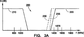
ダイプレクサは、典型的には、使用される特定の通信バンドに応答して通信信号を方向付けるために使用される。例えば、ダイプレクサ140は、アンテナ110上で受信された信号をPCSパスまたはセルラーパスに分離する。図3Aは、ダイプレクサ140に対する例示的な複合周波数応答200を示す。周波数応答200は、ローパスフィルタのローパスフィルタ特性210およびダイプレクサ140のハイパスフィルタのハイパスフィルタ特性220を含む。ローパスフィルタ特性210は、約1000MHzのカットオフ周波数を用いて示され、セルラーバンドを通過するように設計される。ハイパスフィルタ特性220は、約1600MHzのカットオフ周波数と共に示され、PCSバンドを通過するように設計される。カットオフ周波数は、特定の用途に適応するように調整され得、かつ他のカットオフ周波数は、他の通信バンドのために選択され得ることが理解される。ハイパスフィルタ特性220は、ある受理可能な減衰のレベルでGPSバンドにおけるある信号を通過させるように設計される。
Diplexers are typically used to direct communication signals in response to the particular communication band used. For example, the
動作中では、少なくとも1つの無線通信バンドからの無線通信信号がアンテナ110によって受信される。ダイプレクサ140は、無線通信信号を少なくとも第1の信号および第2の信号に分割する。第1の信号は、ダイプレクサ140のローパスフィルタによってフィルタリングされ、次いで、第1のバンドのデュプレクサ150に接続される。第2の信号は、ダイプレクサ140のハイパスフィルタによってフィルタリングされ、次いで、スイッチングモジュール170に接続される。
In operation, a wireless communication signal from at least one wireless communication band is received by the
例示的な実施形態では、無線通信信号が、例えばセルラーバンド通信信号を含み、次いでローパスフィルタは、セルラーバンド通信信号を第1のバンドデュプレクサ150に通過させる。次いで第1のバンドデュプレクサ150は、例えばセルラーレシーバ(図示せず)に入来セルラーバンド通信信号を接続させ得る。さらに、ローパスフィルタは、より高い周波数バンドが第1のバンドデュプレクサ150に通過することを阻止する。
In the exemplary embodiment, the wireless communication signal includes, for example, a cellular band communication signal, and then the low pass filter passes the cellular band communication signal to the
無線通信信号は、例えば、PCSバンド通信信号を含む場合、ダイプレクサ140のハイパスフィルタは、PCSバンド通信信号を第2のバンドデュプレクサ160にスイッチングモジュール170を介して通過させる。無線通信信号は、例えば、GPSバンド信号を含む場合、このハイパスフィルタが、スイッチングモジュール170を介してGPSモジュール175にGPSバンド信号をある少量の減衰で通過させる。例示的な実施形態では、この減衰が部分的に引き起こされる。なぜなら、アンテナ110は、GPSバンドに対して本来最適化されなかった既存のデュアルバンドアンテナであるためである。
For example, when the wireless communication signal includes a PCS band communication signal, the high pass filter of the
GPSモジュール175では、インピーダンス整合モジュール180は、GPSバンドに対してチューニングされるインピーダンス整合を提供する。次いでGPS信号は、従来のGPS回路(図示されない)によって処理される前に、GPS LNA190において増幅される。ハイパスフィルタはまた、より低い周波数バンドを遮断する。
In the
無線通信デバイスは、通常、ダイプレクサ140をデュプレクサ160に接続させるスイッチングモジュール170と共に動作する。しかし、選択された時間または間隔において、所在位置情報を獲得することが望まれることがあり得る。例えば、ユーザが緊急番号をダイヤルする場合、位置情報は有用であり得る。無線デバイスはまた、所在位置が周期的に必要とされるマッピングアプリケーション等のアプリケーションを動作し得る。別の例では、ユーザは、無線デバイスに所在位置情報を獲得するように指示し得る。所在位置情報が有用である、多くのアプリケーションが無線通信デバイスに対して存在することが理解される。
The wireless communication device typically operates with a
所在位置が必要とされ得る場合、スイッチングモジュール170は、アンテナ110をGPSモジュール175に接続させるために制御回路(図示せず)によってスイッチングされる。この態様で構成された場合、約1575MHzにおけるGPSバンド信号は、アンテナによって受信され、GPSモジュール175に伝送される。アンテナ110が、例えば、約800MHzおよび約1900MHzにおいて受信するようにチューニングされたデュアルバンドアンテナであるために、約1575MHzにおけるGPS信号は、整合されない。従って、整合モジュール180は、GPSモジュール175とアンテナ110との間のインピーダンスをより密接に整合するための整合回路を含む。このような態様では、高品質GPS信号は、GPS LNA190によって頑強に受信され得る。
If the location can be required, the
別の例示的な実施形態では、ダイプレクサ140に存在する合成周波数応答200が、より少ない減衰を用いてGPSバンドを通過させるように適応され得る。従って、図3Aの適応された特性230によって示されたように、ハイパスフィルタ特性220は、例えば約1600MHzから例えば約1400MHzにカットオフ周波数をシフトすることによって修正され得る。適応された特性230は、例えば異なる減衰勾配235等の他の異なるパラメータを有し得る。結果として、GPSバンドは、ハイパスフィルタ特性220よりも適応されたハイパスフィルタ特性230によってより小さく減衰される。例えば、約1600MHz(通常のセルラー/PCSダイプレクサにおけるように)から約1400MHzまでのカットオフ周波数に低くする結果、約1575MHzにおけるGPSバンドは、ダイプレクサ140によって、約−1.3dBから約−0.3dBのわずかな減衰となる。
In another exemplary embodiment, the combined
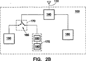
図2Bは、従来の通信アンテナ110を用いてGPS信号を頑強に受信するための回路の別の例を示す。回路は、ダイプレクサ140がアンテナ110上で受信された信号をPCSパスまたはセルラー/GPSパスに分離することを除いて、図2Aに示された回路と同様である。従って、スイッチングモジュール170は、セルラー/GPSパス上に存在する。ダイプレクサ140の周波数応答220の別の例が図3Bに示される。本例では、ダイプレクサ140のローパスフィルタの特性210は、約1575MHzにおいてGPSバンドを含むようにより高い周波数に拡張する。従って、ダイプレクサ140のローパスフィルタは、セルラー/GPSパスにGPSバンド信号を通過させるか、または少量の減衰でGPSバンド信号を通過させる。
FIG. 2B shows another example of a circuit for robustly receiving GPS signals using a
図4は、本発明による無線通信デバイス100の別の例示的実施形態の選択されたコンポーネントを示す。無線通信デバイス100は、例えば、アンテナ110、第1のバンドデュプレクサ150、第2のバンドデュプレクサ160、GPSモジュール175およびトリプレクサ240を含み得る。トリプレクサ240は、アンテナ110を第1のバンドデュプレクサ150、第2のバンドデュプレクサ160、およびGPSモジュール175に接続する。
FIG. 4 illustrates selected components of another exemplary embodiment of a
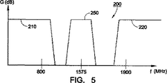
トリプレクサ240に対する例示的な周波数応答200が図5に示され、この応答は、トリプレクサ240におけるローパスフィルタのローパスフィルタ特性210、ハイパスフィルタのハイパスフィルタ特性220、バンドパスフィルタのバンドパスフィルタ特性250を含む。ローパスフィルタ特性210は、例えば、約1000MHzのカットアウト周波数を用いて示され、例えばセルラーバンドを通過させるように設計される。ハイパスフィルタ特性220は、例えば、約1600MHzのカットアウト周波数と共に図示され、例えばPCSバンドを通過させるように設計される。バンドパスフィルタ特性250が、約1575MHzを中心にされ、例えばGPSバンドを通過させるように設計される。特性210、220、250は、オーバラップしてもしなくてもよい。本発明はまた、これらのおよび他の無線通信バンドに対して設計された他のフィルタ特性を用いて企図する。
An
動作中に、少なくとも1つの無線通信バンドからの無線通信信号がアンテナ110によって受信される。トリプレクサ240は、無線通信信号を少なくとも第1の信号、第2の信号、および第3の信号に分割する。第1の信号は、トリプレクサ240のローパスフィルタによってフィルタリングされ、次いで、第1のバンドデュプレクサ150に接続される。第2の信号は、トリプレクサ240のハイパスフィルタによってフィルタリングされ、次いで、第2のバンドデュプレクサ160に接続される。第3の信号は、トリプレクサ240のバンドパスフィルタによってフィルタリングされ、次いで、GPSモジュール175に接続される。この接続メカニズムはまた、最適な性能のためのインピーダンス変換を含み得る。
In operation, a wireless communication signal from at least one wireless communication band is received by the
例示的実施形態では、無線通信信号は、例えば、セルラーバンド通信信号を含む場合、トリプレクサ240のローパスフィルタは、セルラーバンド通信信号を第1のバンドデュプレクサ150に通過させる。さらに、ローパスフィルタは、より高い周波数バンドが第1のバンドデュプレクサ150に通過することを阻止する。
In the exemplary embodiment, if the wireless communication signal includes, for example, a cellular band communication signal, the low pass filter of
無線通信信号は、例えば、PCSバンド通信信号を含む場合、ハイパスフィルタは、第2のバンドデュプレクサ160にPCSバンド通信信号を通過させる。さらに、ハイパスフィルタは、より低い周波数バンドが第2のバンドデュプレクサ160に通過することを妨げる。
For example, when the wireless communication signal includes a PCS band communication signal, the high-pass filter allows the
無線通信信号が、例えばGPSバンド信号を含む場合、バンドパスフィルタは、GPSバンド信号をGPSモジュール175に通過させる。例示的実施形態では、GPSモジュール175において、インピーダンス整合モジュール180は、GPSバンドに対してチューニングされるインピーダンス整合を提供する。次いで、GPS信号は、従来のGPS回路によって処理される前に、GPS LNA190において増幅される。さらに、バンドパスフィルタは、より高いおよびより低い周波数バンドがGPSモジュール175に通過することを阻止する。
If the wireless communication signal includes, for example, a GPS band signal, the band pass filter passes the GPS band signal to the
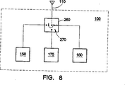
図8は、スイッチングモジュール260が本発明に従ってトリプレクサ240の代わりに使用される別の例示的実施形態を示す。アンテナ110は、スイッチングモジュール260を介して第1のバンドデュプレクサ150、第2のバンドデュプレクサ160、およびGPSモジュール175に接続される。スイッチングモジュール260は、例えば、3方向スイッチ270を含み得る。スイッチングモジュール260は、例えばプロセッサ等の無線通信デバイス100(例えば、モバイルステーションモデム(MSM))のメインコントローラ(図示せず)を介して制御され得る。スイッチングモジュール260は、アンテナ110を介して受信された信号をスイッチングする。従って、例えば、セルラーバンド信号は、第1のバンドデュプレクサ150にスイッチングされ得るか、PCSバンド信号が、第2のバンドデュプレクサ160にスイッチングされ得るか、またはGPS信号は、GPSモジュール175にスイッチングされ得る。セルラー通信回路およびPCS通信回路は、例えば、各バンドと共に使用するためのバンド最適化信号整合回路を含み得る。
FIG. 8 illustrates another exemplary embodiment in which the
図9は、本発明による無線通信デバイス100のさらに別の例示的実施形態を示す。本例示的な実施形態では、無線通信デバイス100は、GPS信号または通信バンド信号(例えば、セルラーバンド信号またはPCSバンド信号)を受信するように構成される。アンテナ110は、スイッチングモジュール260を介してGPSモジュール175および通信バンドデュプレクサ290に接続される。スイッチングモジュール260は、例えば、2方向スイッチ280を含み得る。スイッチングモジュール260は、例えばプロセッサ等の無線通信デバイス100(例えば、モバイルステーションモデム(MSM))のメインコントローラ(図示せず)を介して制御され得る。スイッチングモジュール260は、アンテナ110を介して受信された信号をスイッチングする。従って、例えば、無線通信デバイス100が携帯電話である場合、セルラーバンド信号は、通信バンドデュプレクサ290にスイッチングされてもよいし、GPS信号がGPSモジュール175にスイッチングされてもよい。通信バンド回路は、例えば、通信バンドと共に使用するためのバンドに最適化された信号整合回路を含み得る。
FIG. 9 illustrates yet another exemplary embodiment of a
整合モジュール180または他の整合回路が種々の広範囲の回路を用いてインプリメントされ得ることが理解される。図6は、整合回路をインプリメントするこのような変形の1つを示す。図6では、整合モジュール180への入力は、第1のインダクタL1に接続される。第1のインダクタL1は、第2のインダクタL2を介して整合モジュール180の出力に接続される。第1のインダクタL1はまた、キャパシタC1を介して、電位V1(例えば、電気的またはシャーシグランド)に接続される。このような整合回路は従来から周知である。整合モジュール180は、種々の他の整合回路およびその二重等価回路(dual equivalent)を含み得る。このような整合回路はまた、例えば、当業者に公知であるような受動素子および/または能動素子を含み得る。
It will be appreciated that the
スイッチングモジュール170がいくつかの回路構成でインプリメントされ得ることもまた理解される。図7は、本発明によるスイッチングモジュール170の1つのこのような構成を示す。スイッチングモジュール170への入力は、第1のキャパシタC2に接続される。第1のキャパシタC2は、第1のインダクタL3を介して電位V2(例えばバッテリ電源電圧)に接続される。第1のキャパシタC2はまた、2つの出力分岐に接続される。回路の第1のブランチでは、第1のキャパシタC2は第1のダイオードD1に接続される。第1のダイオードD1は、第2のキャパシタC3を介して第1の出力に接続される。第1のダイオードD1はまた、第2のインダクタL4を介して第1の制御信号に接続される。回路の第2のブランチでは、第1のキャパシタC2は、第2のダイオードD2に接続される。第2のダイオードD2は、第3のキャパシタC4を介して第2の出力に接続される。第2のダイオードD2はまた、第3のインダクタL5を介して第2の制御信号に接続される。簡単には、第1の制御信号および第2の制御信号は、ダイオードD1およびD2間の所望の電位差を供給し、ダイオードD1、D2の各々をターンオンまたはターンオフのいずれかを行う(すなわち、ほとんど短絡またはほぼオープン回路)。スイッチングモジュール170は、当業者に公知の他のスイッチング回路の改変および例をインプリメントし得る。
It is also understood that the
従って、GPS有効アンテナを提供するためのシステムおよび方法が提供されることが理解される。当業者は、本発明が例示および限定しない目的のために、本説明において提示される好適な実施形態以外によって実施され得、そして本発明は、上記特許請求の範囲のみによって限定されないことを理解する。なお、本説明において説明された特定の実施形態に対する均等物が本発明を同様に実施し得る。 Accordingly, it is understood that a system and method for providing a GPS effective antenna is provided. Those skilled in the art will appreciate that the present invention may be practiced other than the preferred embodiments presented in this description for purposes of illustration and limitation, and that the present invention is not limited only by the following claims. . It should be noted that equivalents to the specific embodiments described in this description can similarly implement the invention.
Claims (14)
アンテナ(110)と、
該アンテナに接続されているダイプレクサ(140)であって、第1の通信バンドの複数の第1のバンド信号を該ダイプレクサ(140)の第1のポート上および第2の通信バンドの複数の第2のバンド信号を該ダイプレクサ(140)の第2のポート上に分離するダイプレクサ(140)と、
該ダイプレクサ(140)の該第1のポートに接続されている第1の通信バンドデュプレクサ(150)であって、該第1の通信バンドにおける2つの周波数を同時に送受信することを提供する第1の通信バンドデュプレクサ(150)と、
該ダイプレクサ(140)の該第2のポートに接続されているスイッチングモジュール(170)であって、該複数の第2のバンド信号を該スイッチングモジュール(170)の第1のスイッチ出力上、または、該スイッチングモジュール(170)の第2のスイッチポート上に選択的に結合するように構成されているスイッチングモジュール(170)と、
該スイッチングモジュール(170)の該第2のスイッチポートに接続されている第2の通信バンドデュプレクサ(160)であって、該第2の通信バンドにおける2つの周波数を同時に送受信することを提供する第2の通信バンドデュプレクサ(160)と、
該スイッチングモジュール(170)の該第1のスイッチ出力に接続されているグローバルポジショニングシステム(GPS)モジュール(175)であって、GPS信号周波数のみを受信するグローバルポジショニングシステム(GPS)モジュール(175)と
を備え、
該GPSモジュール(175)は、およそ該GPS信号周波数におけるインピーダンスを整合するように構成されているインピーダンス整合回路(180)を備え、
該GPS信号周波数は、該第1の通信バンドの該2つの周波数が同時に送受信されるのと同一の期間に受信されるように選択されることが可能である、デバイス。A global positioning system (GPS) enabled wireless communication device,
An antenna (110);
A diplexer (140) connected to the antenna, wherein a plurality of first band signals of a first communication band are transmitted on a first port of the diplexer (140) and a plurality of first bands of a second communication band. A diplexer (140) separating two band signals onto a second port of the diplexer (140);
A first communication band duplexer (150) connected to the first port of the diplexer (140), the first communication band duplexer (150) providing simultaneous transmission and reception of two frequencies in the first communication band Communication band duplexer (150),
A switching module (170) connected to the second port of the diplexer (140), wherein the plurality of second band signals are transmitted on a first switch output of the switching module (170), or A switching module (170) configured to selectively couple onto a second switch port of the switching module (170);
A second communication band duplexer (160) connected to the second switch port of the switching module (170) for providing simultaneous transmission and reception of two frequencies in the second communication band. 2 communication band duplexers (160);
A global positioning system (GPS) module (175) connected to the first switch output of the switching module (170), wherein the global positioning system (GPS) module (175) receives only GPS signal frequencies; With
The GPS module (175) comprises an impedance matching circuit (180) configured to match impedance at approximately the GPS signal frequency;
The GPS signal frequency may be selected such that it is received in the same period as the two frequencies of the first communication band are transmitted and received simultaneously .
Applications Claiming Priority (2)
| Application Number | Priority Date | Filing Date | Title |
|---|---|---|---|
| US09/898,269 US6865376B2 (en) | 2001-07-03 | 2001-07-03 | System and method for a GPS enabled antenna |
| PCT/IB2002/002567 WO2003005056A2 (en) | 2001-07-03 | 2002-07-03 | System and method for a gps enabled antenna |
Publications (3)
| Publication Number | Publication Date |
|---|---|
| JP2004536508A JP2004536508A (en) | 2004-12-02 |
| JP2004536508A5 JP2004536508A5 (en) | 2006-01-05 |
| JP4549672B2 true JP4549672B2 (en) | 2010-09-22 |
Family
ID=25409187
Family Applications (1)
| Application Number | Title | Priority Date | Filing Date |
|---|---|---|---|
| JP2003510979A Expired - Fee Related JP4549672B2 (en) | 2001-07-03 | 2002-07-03 | System and method for GPS effective antenna |
Country Status (10)
| Country | Link |
|---|---|
| US (3) | US6865376B2 (en) |
| EP (1) | EP1402651B1 (en) |
| JP (1) | JP4549672B2 (en) |
| KR (1) | KR100927309B1 (en) |
| CN (1) | CN100578948C (en) |
| AT (1) | ATE315288T1 (en) |
| AU (1) | AU2002314443A1 (en) |
| DE (1) | DE60208555T2 (en) |
| ES (1) | ES2254694T3 (en) |
| WO (1) | WO2003005056A2 (en) |
Families Citing this family (24)
| Publication number | Priority date | Publication date | Assignee | Title |
|---|---|---|---|---|
| US7181171B2 (en) * | 2001-07-20 | 2007-02-20 | Kyocera Wireless Corp. | System and method for providing auxiliary reception in a wireless communications system |
| US7729698B2 (en) * | 2001-09-27 | 2010-06-01 | Qualcomm Incorporated | Communication system receiver and method for concurrent receiving of multiple channels |
| US6912406B2 (en) * | 2002-02-13 | 2005-06-28 | Motorola Inc. | Apparatus for multiple band communication |
| JP3727888B2 (en) * | 2002-02-19 | 2005-12-21 | 株式会社東芝 | Mobile communication terminal and its external devices |
| KR20040052286A (en) * | 2002-12-16 | 2004-06-23 | 삼성전기주식회사 | High frequency composite component |
| US6845231B2 (en) * | 2003-03-24 | 2005-01-18 | Agilent Technologies, Inc. | Method facilitating inter-mode handoff |
| US7376440B2 (en) * | 2003-04-16 | 2008-05-20 | Kyocera Wireless Corp. | N-plexer systems and methods for use in a wireless communications device |
| KR100531879B1 (en) | 2003-07-09 | 2005-11-29 | 엘지전자 주식회사 | Radio frequency reception circuit for mobile phone |
| JP4828798B2 (en) * | 2004-01-30 | 2011-11-30 | 株式会社東芝 | Electronics |
| US7546091B2 (en) | 2004-03-16 | 2009-06-09 | Hitachi Metals, Ltd. | High-frequency circuit and high-frequency device |
| US20050245201A1 (en) * | 2004-04-30 | 2005-11-03 | Nokia Corporation | Front-end topology for multiband multimode communication engines |
| US7187945B2 (en) * | 2004-04-30 | 2007-03-06 | Nokia Corporation | Versatile antenna switch architecture |
| US7376446B2 (en) * | 2004-07-15 | 2008-05-20 | Nokia Siemens Networks Gmbh & Co. Kg | Mobile communications network with expanded carrier capacity and method of expanding base station carrier capacity |
| US20060067254A1 (en) * | 2004-09-27 | 2006-03-30 | Sawtek, Inc. | Triband passive signal receptor network |
| KR100712910B1 (en) * | 2005-01-06 | 2007-05-02 | 엘지전자 주식회사 | Mobile communication terminal with GPS |
| US8738103B2 (en) | 2006-07-18 | 2014-05-27 | Fractus, S.A. | Multiple-body-configuration multimedia and smartphone multifunction wireless devices |
| TWI387222B (en) * | 2008-04-09 | 2013-02-21 | Inventec Appliances Corp | A handheld device which can switch signal receiving modes |
| EP2279566A4 (en) * | 2008-05-06 | 2015-01-21 | Hollinworth Fund L L C | Single cable antenna module for laptop computer and mobile devices |
| US11063625B2 (en) | 2008-08-14 | 2021-07-13 | Theodore S. Rappaport | Steerable antenna device |
| US8589942B2 (en) * | 2010-05-07 | 2013-11-19 | Qualcomm Incorporated | Non-real time thread scheduling |
| JP2012253497A (en) * | 2011-06-01 | 2012-12-20 | Taiyo Yuden Co Ltd | Electronic circuit and electronic module |
| WO2015133319A1 (en) * | 2014-03-05 | 2015-09-11 | ソニー株式会社 | Receiver device and reception method |
| US10252466B2 (en) * | 2014-07-28 | 2019-04-09 | Massachusetts Institute Of Technology | Systems and methods of machine vision assisted additive fabrication |
| US10456984B2 (en) | 2016-12-16 | 2019-10-29 | Massachusetts Institute Of Technology | Adaptive material deposition for additive manufacturing |
Family Cites Families (54)
| Publication number | Priority date | Publication date | Assignee | Title |
|---|---|---|---|---|
| US4091344A (en) | 1977-01-19 | 1978-05-23 | Wavecom Industries | Microwave multiplexer having resonant circuits connected in series with comb-line bandpass filters |
| JPH0820503B2 (en) * | 1987-07-29 | 1996-03-04 | 古野電気株式会社 | Earth station transmitter / receiver for satellite navigation and satellite communications |
| US4902992A (en) | 1988-03-29 | 1990-02-20 | The United States Of America As Represented By The Secretary Of The Navy | Millimeter-wave multiplexers |
| JPH06188622A (en) | 1992-12-16 | 1994-07-08 | Murata Mfg Co Ltd | Antenna multicoupler |
| JP3139327B2 (en) | 1995-05-31 | 2001-02-26 | 株式会社村田製作所 | High frequency composite parts |
| WO1997015092A1 (en) | 1995-10-13 | 1997-04-24 | Peter Nielsen | Method and system for communicating electromagnetic signals |
| US5771026A (en) | 1996-03-28 | 1998-06-23 | Sti-Co Industries, Inc. | Disguised broadband antenna system for vehicles |
| GB9606593D0 (en) * | 1996-03-29 | 1996-06-05 | Symmetricom Inc | An antenna system |
| FI102432B1 (en) | 1996-09-11 | 1998-11-30 | Lk Products Oy | Antenna filtering device for a dual-acting radio communication device |
| US5815804A (en) | 1997-04-17 | 1998-09-29 | Motorola | Dual-band filter network |
| US5969582A (en) * | 1997-07-03 | 1999-10-19 | Ericsson Inc. | Impedance matching circuit for power amplifier |
| US6097974A (en) * | 1997-12-12 | 2000-08-01 | Ericsson Inc. | Combined GPS and wide bandwidth radiotelephone terminals and methods |
| US6148022A (en) | 1998-01-28 | 2000-11-14 | The Aerospace Corporation | NRZ and biphase-L formatted quadriphase modulated GPS transmission method |
| JP3898830B2 (en) | 1998-03-04 | 2007-03-28 | 株式会社日立製作所 | Multiband wireless terminal device |
| EP0959567A1 (en) | 1998-05-19 | 1999-11-24 | Robert Bosch Gmbh | Diplexer for mobile phone |
| DE19823060C2 (en) * | 1998-05-22 | 2001-02-22 | Ericsson Telefon Ab L M | Power amplifier output circuit |
| JP2000013278A (en) * | 1998-06-25 | 2000-01-14 | Matsushita Electric Ind Co Ltd | Radio device, radio portable equipment provided with it, radio base station and radio communication system including them |
| US6088348A (en) * | 1998-07-13 | 2000-07-11 | Qualcom Incorporated | Configurable single and dual VCOs for dual- and tri-band wireless communication systems |
| US6298243B1 (en) * | 1999-01-05 | 2001-10-02 | Geo-Com, Incorporated | Combined GPS and cellular band mobile antenna |
| GB2346049A (en) * | 1999-01-19 | 2000-07-26 | Roke Manor Research | Duplex filtering |
| SE9904256D0 (en) | 1999-02-10 | 1999-11-24 | Allgon Ab | An antenna device and a radio communication device including an antenna device |
| JP2002064301A (en) * | 1999-03-18 | 2002-02-28 | Hitachi Metals Ltd | High frequency switch module for triple band |
| US6553210B1 (en) * | 1999-08-03 | 2003-04-22 | Alliedsignal Inc. | Single antenna for receipt of signals from multiple communications systems |
| AU7586500A (en) * | 1999-09-17 | 2001-04-17 | Qualcomm Incorporated | System and method for synchronizing base stations in cellular and pcs networks |
| KR100317269B1 (en) * | 1999-10-22 | 2001-12-22 | 서평원 | Mobile Station mounting GPS |
| US7003312B2 (en) * | 1999-12-28 | 2006-02-21 | Hitachi Metals, Ltd. | High-frequency switch circuit, high-frequency switch module and wireless communication device |
| US6694150B1 (en) * | 2000-02-12 | 2004-02-17 | Qualcomm, Incorporated | Multiple band wireless telephone with multiple antennas |
| US6625470B1 (en) | 2000-03-02 | 2003-09-23 | Motorola, Inc. | Transmitter |
| US6674337B2 (en) * | 2000-03-28 | 2004-01-06 | California Institute Of Technology | Concurrent multi-band low noise amplifier architecture |
| US6678512B1 (en) | 2000-04-14 | 2004-01-13 | Lucent Technologies Inc. | Receiver system using analog to digital conversion at radio frequency and method |
| US6351236B1 (en) * | 2000-04-25 | 2002-02-26 | Agilent Technologies, Inc. | Combined GPS and CDMA in a mobile transceiver |
| JP4524864B2 (en) | 2000-06-08 | 2010-08-18 | パナソニック株式会社 | Multi-frequency antenna duplexer |
| KR100611421B1 (en) * | 2000-08-21 | 2006-08-09 | 티디케이가부시기가이샤 | Front end module for mobile communications apparatus |
| JP4049239B2 (en) | 2000-08-30 | 2008-02-20 | Tdk株式会社 | Method for manufacturing high-frequency module component including surface acoustic wave element |
| JP2002171315A (en) | 2000-12-01 | 2002-06-14 | Toshiba Corp | On-vehicle portable terminal equipment |
| CN1251403C (en) * | 2000-12-22 | 2006-04-12 | 宇部兴产株式会社 | Multiplexer |
| US6694129B2 (en) * | 2001-01-12 | 2004-02-17 | Qualcomm, Incorporated | Direct conversion digital domain control |
| US20020163391A1 (en) * | 2001-03-01 | 2002-11-07 | Peterzell Paul E. | Local oscillator leakage control in direct conversion processes |
| US20020123319A1 (en) * | 2001-03-01 | 2002-09-05 | Peterzell Paul E. | Direct conversion digital domain control |
| US6961368B2 (en) * | 2001-01-26 | 2005-11-01 | Ericsson Inc. | Adaptive antenna optimization network |
| US6801767B1 (en) | 2001-01-26 | 2004-10-05 | Lgc Wireless, Inc. | Method and system for distributing multiband wireless communications signals |
| US20020107033A1 (en) * | 2001-02-08 | 2002-08-08 | Kim Seung Kil | Method and apparatus for use of GPS and cellular antenna combination |
| JP4505777B2 (en) * | 2001-02-26 | 2010-07-21 | 日立金属株式会社 | Frequency demultiplexing circuit and multi-band antenna switch laminated module composite parts |
| US6917815B2 (en) * | 2001-03-14 | 2005-07-12 | California Institute Of Technology | Concurrent dual-band receiver architecture |
| US6456941B1 (en) * | 2001-03-26 | 2002-09-24 | William Gutierrez | System and method for aircraft and watercraft control and collision prevention |
| US6667723B2 (en) * | 2001-07-03 | 2003-12-23 | Kyocera Wireless Corp. | System and method for a GPS enabled antenna |
| FR2828624A1 (en) | 2001-08-09 | 2003-02-14 | Sagem | TRANSMISSION / RECEPTION SYSTEM FOR MULTIBAND AND MULTIMODE MOBILE TELEPHONE |
| US6597258B2 (en) | 2001-08-30 | 2003-07-22 | Spectrum Astro | High performance diplexer and method |
| US6785543B2 (en) | 2001-09-14 | 2004-08-31 | Mobile Satellite Ventures, Lp | Filters for combined radiotelephone/GPS terminals |
| CN1225092C (en) | 2001-10-13 | 2005-10-26 | 三星电子株式会社 | Mobile communication system having multi-band antenna |
| US6853909B2 (en) * | 2001-12-03 | 2005-02-08 | Applanix Corporation, Inc | Walking stick navigator for position determination |
| US20040072551A1 (en) | 2002-10-10 | 2004-04-15 | Sanford John Richard | Communication device with front-end integration |
| US7245897B2 (en) | 2003-03-10 | 2007-07-17 | Intel Corporation | Using an electroacoustic resonator |
| US6980067B2 (en) | 2003-04-16 | 2005-12-27 | Kyocera Wireless Corp. | Triplexer systems and methods for use in wireless communications device |
-
2001
- 2001-07-03 US US09/898,269 patent/US6865376B2/en not_active Expired - Lifetime
-
2002
- 2002-07-03 CN CN02812845A patent/CN100578948C/en not_active Expired - Fee Related
- 2002-07-03 AT AT02741034T patent/ATE315288T1/en not_active IP Right Cessation
- 2002-07-03 AU AU2002314443A patent/AU2002314443A1/en not_active Abandoned
- 2002-07-03 DE DE60208555T patent/DE60208555T2/en not_active Expired - Lifetime
- 2002-07-03 EP EP02741034A patent/EP1402651B1/en not_active Expired - Lifetime
- 2002-07-03 JP JP2003510979A patent/JP4549672B2/en not_active Expired - Fee Related
- 2002-07-03 ES ES02741034T patent/ES2254694T3/en not_active Expired - Lifetime
- 2002-07-03 KR KR1020037017187A patent/KR100927309B1/en not_active IP Right Cessation
- 2002-07-03 WO PCT/IB2002/002567 patent/WO2003005056A2/en active IP Right Grant
-
2005
- 2005-03-04 US US11/073,312 patent/US7542727B2/en not_active Expired - Fee Related
- 2005-03-07 US US11/074,902 patent/US6973307B2/en not_active Expired - Lifetime
Also Published As
| Publication number | Publication date |
|---|---|
| US6973307B2 (en) | 2005-12-06 |
| DE60208555T2 (en) | 2006-11-16 |
| WO2003005056A2 (en) | 2003-01-16 |
| ES2254694T3 (en) | 2006-06-16 |
| ATE315288T1 (en) | 2006-02-15 |
| US6865376B2 (en) | 2005-03-08 |
| CN100578948C (en) | 2010-01-06 |
| JP2004536508A (en) | 2004-12-02 |
| KR100927309B1 (en) | 2009-11-18 |
| CN1537361A (en) | 2004-10-13 |
| WO2003005056A3 (en) | 2003-06-05 |
| US20050153709A1 (en) | 2005-07-14 |
| AU2002314443A1 (en) | 2003-01-21 |
| KR20040014598A (en) | 2004-02-14 |
| DE60208555D1 (en) | 2006-03-30 |
| US20030008660A1 (en) | 2003-01-09 |
| US7542727B2 (en) | 2009-06-02 |
| EP1402651B1 (en) | 2006-01-04 |
| US20050191967A1 (en) | 2005-09-01 |
| EP1402651A2 (en) | 2004-03-31 |
Similar Documents
| Publication | Publication Date | Title |
|---|---|---|
| JP4549672B2 (en) | System and method for GPS effective antenna | |
| JP4484871B2 (en) | Frequency selective device and method of receiving / transmitting communication signal in wireless multiband device thereof | |
| US6667723B2 (en) | System and method for a GPS enabled antenna | |
| US6980067B2 (en) | Triplexer systems and methods for use in wireless communications device | |
| US6816711B2 (en) | GPS equipped mobile phone with single shared antenna | |
| US6510310B1 (en) | Dual mode phone architecture utilizing a single transmit-receive switch | |
| US9094098B2 (en) | Multi-band radio frequency (RF) communication device using a single antenna | |
| US20060067254A1 (en) | Triband passive signal receptor network | |
| US7383032B2 (en) | Cellular phone and method for receiving and transmitting signals of different frequency bands | |
| US7356314B2 (en) | Systems and methods for reusing a low noise amplifier in a wireless communications device | |
| JP2004228666A (en) | Antenna duplexer | |
| JP2003168995A (en) | Communication device | |
| KR20050108287A (en) | Radio frequency transceiver of portable terminal having multiband multimode function, and portable terminal having thereof |
Legal Events
| Date | Code | Title | Description |
|---|---|---|---|
| A521 | Request for written amendment filed |
Free format text: JAPANESE INTERMEDIATE CODE: A523 Effective date: 20050701 |
|
| A621 | Written request for application examination |
Free format text: JAPANESE INTERMEDIATE CODE: A621 Effective date: 20050701 |
|
| A977 | Report on retrieval |
Free format text: JAPANESE INTERMEDIATE CODE: A971007 Effective date: 20080701 |
|
| A131 | Notification of reasons for refusal |
Free format text: JAPANESE INTERMEDIATE CODE: A131 Effective date: 20080725 |
|
| A601 | Written request for extension of time |
Free format text: JAPANESE INTERMEDIATE CODE: A601 Effective date: 20081024 |
|
| A602 | Written permission of extension of time |
Free format text: JAPANESE INTERMEDIATE CODE: A602 Effective date: 20081031 |
|
| A601 | Written request for extension of time |
Free format text: JAPANESE INTERMEDIATE CODE: A601 Effective date: 20081121 |
|
| A602 | Written permission of extension of time |
Free format text: JAPANESE INTERMEDIATE CODE: A602 Effective date: 20081201 |
|
| A601 | Written request for extension of time |
Free format text: JAPANESE INTERMEDIATE CODE: A601 Effective date: 20081219 |
|
| A602 | Written permission of extension of time |
Free format text: JAPANESE INTERMEDIATE CODE: A602 Effective date: 20090105 |
|
| A521 | Request for written amendment filed |
Free format text: JAPANESE INTERMEDIATE CODE: A523 Effective date: 20090126 |
|
| A131 | Notification of reasons for refusal |
Free format text: JAPANESE INTERMEDIATE CODE: A131 Effective date: 20091002 |
|
| A601 | Written request for extension of time |
Free format text: JAPANESE INTERMEDIATE CODE: A601 Effective date: 20091225 |
|
| A602 | Written permission of extension of time |
Free format text: JAPANESE INTERMEDIATE CODE: A602 Effective date: 20100107 |
|
| A601 | Written request for extension of time |
Free format text: JAPANESE INTERMEDIATE CODE: A601 Effective date: 20100201 |
|
| A602 | Written permission of extension of time |
Free format text: JAPANESE INTERMEDIATE CODE: A602 Effective date: 20100208 |
|
| A601 | Written request for extension of time |
Free format text: JAPANESE INTERMEDIATE CODE: A601 Effective date: 20100301 |
|
| A602 | Written permission of extension of time |
Free format text: JAPANESE INTERMEDIATE CODE: A602 Effective date: 20100308 |
|
| A521 | Request for written amendment filed |
Free format text: JAPANESE INTERMEDIATE CODE: A523 Effective date: 20100402 |
|
| TRDD | Decision of grant or rejection written | ||
| A01 | Written decision to grant a patent or to grant a registration (utility model) |
Free format text: JAPANESE INTERMEDIATE CODE: A01 Effective date: 20100611 |
|
| A01 | Written decision to grant a patent or to grant a registration (utility model) |
Free format text: JAPANESE INTERMEDIATE CODE: A01 |
|
| A61 | First payment of annual fees (during grant procedure) |
Free format text: JAPANESE INTERMEDIATE CODE: A61 Effective date: 20100707 |
|
| R150 | Certificate of patent or registration of utility model |
Free format text: JAPANESE INTERMEDIATE CODE: R150 |
|
| FPAY | Renewal fee payment (event date is renewal date of database) |
Free format text: PAYMENT UNTIL: 20130716 Year of fee payment: 3 |
|
| S111 | Request for change of ownership or part of ownership |
Free format text: JAPANESE INTERMEDIATE CODE: R313113 |
|
| FPAY | Renewal fee payment (event date is renewal date of database) |
Free format text: PAYMENT UNTIL: 20130716 Year of fee payment: 3 |
|
| R371 | Transfer withdrawn |
Free format text: JAPANESE INTERMEDIATE CODE: R371 |
|
| FPAY | Renewal fee payment (event date is renewal date of database) |
Free format text: PAYMENT UNTIL: 20130716 Year of fee payment: 3 |
|
| S111 | Request for change of ownership or part of ownership |
Free format text: JAPANESE INTERMEDIATE CODE: R313113 |
|
| FPAY | Renewal fee payment (event date is renewal date of database) |
Free format text: PAYMENT UNTIL: 20130716 Year of fee payment: 3 |
|
| R350 | Written notification of registration of transfer |
Free format text: JAPANESE INTERMEDIATE CODE: R350 |
|
| R250 | Receipt of annual fees |
Free format text: JAPANESE INTERMEDIATE CODE: R250 |
|
| R250 | Receipt of annual fees |
Free format text: JAPANESE INTERMEDIATE CODE: R250 |
|
| R250 | Receipt of annual fees |
Free format text: JAPANESE INTERMEDIATE CODE: R250 |
|
| R250 | Receipt of annual fees |
Free format text: JAPANESE INTERMEDIATE CODE: R250 |
|
| LAPS | Cancellation because of no payment of annual fees |