JP4546603B2 - Eye point position variable barrel and microscope using the same - Google Patents
Eye point position variable barrel and microscope using the same Download PDFInfo
- Publication number
- JP4546603B2 JP4546603B2 JP2000076351A JP2000076351A JP4546603B2 JP 4546603 B2 JP4546603 B2 JP 4546603B2 JP 2000076351 A JP2000076351 A JP 2000076351A JP 2000076351 A JP2000076351 A JP 2000076351A JP 4546603 B2 JP4546603 B2 JP 4546603B2
- Authority
- JP
- Japan
- Prior art keywords
- optical system
- lens
- optical
- lens barrel
- eyepiece
- Prior art date
- Legal status (The legal status is an assumption and is not a legal conclusion. Google has not performed a legal analysis and makes no representation as to the accuracy of the status listed.)
- Expired - Fee Related
Links
Images


Classifications
-
- G—PHYSICS
- G02—OPTICS
- G02B—OPTICAL ELEMENTS, SYSTEMS OR APPARATUS
- G02B7/00—Mountings, adjusting means, or light-tight connections, for optical elements
- G02B7/20—Light-tight connections for movable optical elements
- G02B7/24—Pivoted connections
-
- G—PHYSICS
- G02—OPTICS
- G02B—OPTICAL ELEMENTS, SYSTEMS OR APPARATUS
- G02B21/00—Microscopes
- G02B21/24—Base structure
Landscapes
- Physics & Mathematics (AREA)
- General Physics & Mathematics (AREA)
- Optics & Photonics (AREA)
- Chemical & Material Sciences (AREA)
- Analytical Chemistry (AREA)
- Lenses (AREA)
- Lens Barrels (AREA)
- Microscoopes, Condenser (AREA)
Description
【0001】
【発明の属する技術分野】
本発明は、アイポイント位置可変の鏡筒と、それを用いた顕微鏡に関する。
【0002】
【従来の技術】
顕微鏡の観察に使用される鏡筒は、接眼レンズを覗く眼の位置(アイポイント)を、観察が容易で且つ楽な姿勢をとることが出来るような鏡筒にするため、従来さまざまな提案がなされている。
例えば、特開平4−166907号では、双眼部の接眼レンズを覗き込む角度である俯角を調整する機構を備えたティルティング鏡筒が提案されている。ここでは、俯角を変化させることでアイポイントの高さと位置を変えるようにしている。
また、特開平8−278448号では、対物レンズからの光束を偏向部材により偏向させることによって、アイポイントの位置を下げることを提案している。これは、予めアイポイント位置を下げることによって楽な姿勢で観察することを目的としている。
また、特開平10−142473号では、俯角を変化させるティルティング機構とこれを観察光軸に沿って移動させる機構とを備えた鏡筒を提案している。これは、アイポイント位置の高さと対物レンズの光軸と観察者の眼の位置までの水平方向の距離を夫々変化させることを目的としている。
また、特開平9−73031号では、対物レンズと可動鏡筒の結像レンズとの間がアフォーカルとなる光学系を有する顕微鏡において、対物レンズと結像レンズとの間のアフォーカル光束中で光束を第1の偏向部材で水平方向に偏向させ、更に第2の偏向部材によってこれを90度偏向させて、結像レンズへ入射させ、前記第1の偏向部材と第2の偏向部材との間にガイドを設け、第1の偏向部材と前記可動鏡筒を一体に移動させて、アイポイント位置を変化させるようにしている。
【0003】
【発明が解決しようとする課題】
顕微鏡観察において、観察者が楽な姿勢で観察できるようにすることは非常に重要なことであり、長時間に多くの試料や標本を検査する場合には、疲労や検査の見落としを防止するうえで重要な点である。図13は一般的な顕微鏡の外寸を示しているが、観察者の疲労を軽減するためには、背の高い大柄な人と背の低い小柄な人が同じ顕微鏡を使って観察する場合、一般的には、1)机上面2から接眼レンズOCのアイポイント位置Eまでの高さHと、2)接眼レンズOCを覗き込むときの角度(俯角)θと、3)対物レンズ光軸から接眼レンズのアイポイント位置Eまでの水平距離dの3つが、適切な値であることが重要である。長時間無理のない姿勢で観察することを可能にするためには、体型に拘わらず準焦ハンドル3に手を添えたときに、無理のない姿勢で眼の位置に接眼レンズのアイポイント位置Eがあることが必要である。一般的な顕微鏡は、机上面2から試料面1までの高さが200mmであり、顕微鏡本体5の鏡筒側胴付位置8までの高さは机上面2から約305mmである。
【0004】
この顕微鏡に、実開平4−124218号で提案されているティルティング鏡筒を組み合せた場合のアイポイント位置Eの高さは、机上面2から最も低い組み合わせで約400mm程度である。また、俯角θを変化できるティルティング鏡筒の場合、机上面2からの高さは約400mmから500mmの範囲で変化する。また、対物レンズOBの光軸位置から準焦ハンドル3の中心位置までは約100mmであり、一般的な鏡筒では、アイポイント位置Eは、対物レンズOBの光軸から水平方向へ約195mmである。俯角θを変化させることができるティルティング鏡筒では、この水平方向の距離は約140mmから195mmの範囲で変化する。
【0005】
上述した単に俯角を変化させるだけのティルティング鏡筒の場合には、俯角θを変化させた場合に対物レンズOBの光軸とアイポイント位置Eまでの水平方向の距離はわずかしか変化せず、水平からの角度を大きくした場合には、この水平方向の距離が短くなるという欠点がある。これは観察者の体型によらずに、無理のない姿勢で観察するのを不可能にするという問題点がある。例えば背の高い大柄な外国人であれば、対物レンズ光軸からの水平方向の距離は、小柄な女性以上に必要であり、アイポイント高さも当然必要である。例えば身長1580mmの人の場合、最適なアイポイント高さは机上面2から約430mm必要で、身長が1840mmの人の場合、床から机上面2までを70cmとし、観察時の椅子の高さを調節した場合に、最低限必要なアイポイント高さは、机上面2から約510mmで、最適と言われるアイポイント高さは机上面2から約600mm程度である。このアイポイント高さからでも、従来の鏡筒4では、身長1840mmの人では、観察時の姿勢に無理があり、対物レンズ光軸からアイポイント位置までの水平方向の距離も短く、顕微鏡を抱え込んで観察する姿勢に近くなってしまうために、観察時の疲労等が増大するという問題点があった。またティルティング鏡筒にアイポイント高さを調節する中間鏡筒を組み合せた場合、約60mm程度アイポイントの高さを上げるのが限界であり、これ以上の高さにした場合には、ケラレや周辺光量不足が生じてしまうので、ティルティング鏡筒では、背の高い大柄な人では、観察姿勢に無理がある。
【0006】
また特開平10−142473号に提案された鏡筒では、俯角とアイポイント位置を独立して変化させることが可能となっている。しかしながら、特開平10−142473号に提案されているレンズ構成では、対物レンズからの光束を結像させずに接眼レンズの焦点面へリレーさせるようにしているので、鏡筒内の光路長を十分に長くとることができない。従って、実質的に対物レンズから接眼レンズのアイポイント位置までの水平方向距離を十分に離し、かつアイポイント高さも大きく変化させて上述した観察者のさまざまな体格に合わせるような構成を採ることができない。
またアフォーカル部の移動距離を長くとることでアイポイント位置を離すと、レンズや双眼部のプリズム部の有効径が大きくなって、しかも軸外光束の収差性能が悪化したり、射出瞳位置が大きく変化して接眼レンズでケラレが発生してしまうという欠点がある。
また、第1の光学系と第2の光学系のアフォーカル倍率を大きくとり、第3の光学系の焦点距離を長くしてアイポイント位置を離す設計にした場合、第2の光学系を出射した軸外主光線の角度が大きくなるので、結果的に第3の光学系以降の有効径が大きくなったり、周辺の収差性能や、射出瞳位置が一致しなくなるという欠点があった。
さらに、落射照明用のユニットや光路分割ユニットやアイポイント位置を上げるためのユニットを配置した場合に、対物レンズからの光束径が大きくなって、第1の光学系、第2の光学系およびティルティングミラーでの有効径が大きくなって周辺光量不足やケラレが発生するので、中間鏡筒長を長くとることが難しく、これらの光学系の有効径を大きくとった場合は、レンズを限られたスペースの中に配置できなくなるという欠点があった。
つまり特開平10−142473号に提案された鏡筒では、対物レンズ光軸からアイポイント位置までの水平方向の距離とアイポイント高さを十分に大きくすることは難しく、アフォーカル部による第3の光学系の移動距離も30mm程度が限界であるので、観察者のさまざまな体格に合わせて、特に背の高い大柄な人には、最適な観察姿勢を実現させることは難しく、この先行例には、アイポイント位置の高さや、対物レンズ光軸からアイポイント位置までの水平方向の距離などの具体的な数値が開示されておらず、従来の鏡筒に対しての優位性が明確でない。
【0007】
同様に、特開平9−73031号に提案されたものも、アフォーカル光束部の長さを変化させる場合のレンズ群の移動量自体に限界があり、様々な観察者の体格に対応できるほどアイポイント位置を変化させることができない。
【0008】
本発明は、従来の技術の有するこのような問題点に鑑みてなされたものであり、その目的とするところは、どのような体格の人にも、観察姿勢に無理がなく疲労の少ない姿勢で観察することが出来るように、対物レンズ光軸からアイポイント位置までの水平距離とアイポイントの高さと観察時の俯角とを変えることができ、中間鏡筒などのシステム性にも十分に対応可能なアイポイント位置可変鏡筒とそれを用いた顕微鏡を提供しようとするものである。
【0009】
【課題を解決するための手段】
上記目的を達成するために、本発明による鏡筒は、光が入射する側から順に、第1の光学系と、該第1の光学系から射出された光束を平行光束に変換する第2の光学系と、該第2の光学系から射出された平行光束を接眼レンズへ導く第3の光学系とを備え、前記第1の光学系は中間像を形成するレンズ群と、光束を偏向する少なくとも3つの光偏向部材を有し、前記第2の光学系はレンズ群と光偏向部材を有し、前記第1の光学系の前記少なくとも3つの光偏向部材のうち、前記第2の光学系の最も近くに配置された光偏向部材から射出された光束の光軸を第1の光軸とし、前記第2の光学系から射出された平行光束の光軸を第2の光軸としたときに、前記第2の光学系の前記光偏向部材を、前記第1の光軸と前記第2の光軸に対して垂直な軸を中心として回動するように配置し、前記第3の光学系は、前記第2の光学系との間隔が変更可能であり、前記第2の光学系の光軸方向に移動可能に構成されていることを特徴としている。
この構成によれば、入射光束は、第1の光学系によって中間像をつくり、第2の光学系及び第3の光学系によって接眼レンズの焦点面に再結像されて観察される。
接眼レンズでケラレがなく像を観察するためには、接眼レンズの入射瞳位置と鏡筒の出射瞳位置を略一致させる必要があり、第2の光学系と第3の光学系を夫々接眼レンズ1群で構成した場合には、第2の光学系と第3の光学系の間隔は、第2の光学系の焦点距離をF2、第3の光学系の焦点距離をF3とすると、おおよそF2+F3程度の間隔が必要となる。また、第1の光学系による中間像を第2の光学系で平行光束に変換するので、第1の光学系を単レンズで構成すると、第1の光学系と第2の光学系の間隔は、第1の光学系の焦点距離をF1とすると、F1+F2となる。
従って、鏡筒内で中間像をつくる構成にすることで、中間像をつくらない構成に比べて鏡筒内での光学系の光路長を十分に長く構成することが出来るので、鏡筒内の光路のレイアウトによって、アイポイントの位置を設定する自由度が高くなる。
また、第1の光学系中には、光束を偏向させるための少なくとも3つの光学部材をもち、更に回動自在に構成された光学部材をもつので、鏡筒内での光束の偏向による反射回数は4回となり、正立正像の観察となる。また、第2の光学系の光偏向部材と第2の光学系と第3の光学系と接眼レンズが一体となって、第2の光学系の光軸に対して垂直な軸の周りに回動することにより、観察時の俯角を調整することが可能となる。
また、第3の光学系と接眼レンズを一体的に第3の光学系の光軸方向に移動させることで、アイポイント位置を変化させることが可能となり、また第2の光学系の光偏向部材が回動することによって観察時の接眼レンズを覗く俯角を変化させることも可能となり、アイポイント位置の高さ及び対物レンズ光軸からの位置を変化させることが出来る。
【0011】
また、本発明によれば、第2の光学系の光偏向部材が角度α回動したとき、第2の光学系と第3の光学系と接眼レンズが一体となって角度α/2だけ回動するようになっている。
この構成により、第2の光学系の光偏向部材を出射した光軸と接眼レンズの光軸とは常に一致するので、光偏向部材の回動に伴う俯角修正は不要となり、操作性の良い顕微鏡を提供することを可能にする。
【0013】
また、本発明によれば、前記第3の光学系は、第2の光学系側から、正の屈折力をもつ第1レンズ群と、負の屈折力をもつ第2レンズ群と、正の屈折力をもつ第3レンズ群で構成されている。
この構成によれば、第3の光学系を単レンズ(接合レンズを含む)1つで構成した場合に比べて、第2の光学系と第3の光学系の間隔を短くすることができ、接眼レンズの瞳位置を第3の光学系側に近づくようにさせることが可能となるので、従来の接眼レンズが共通に使用可能であり、または、接眼レンズでのケラレを抑えることが可能となる。
後述の実施例1で述べるように、第3の光学系を1群の接合レンズで構成した場合には、第2の光学系と第3の光学系の間隔が短いと、接眼レンズの焦点面での瞳位置は接眼レンズ側に近づいて来るので、接眼レンズの有効径が大きくなったり、周辺でのケラレが生じるなどの接眼レンズの制限が発生する。また、第3の光学系側へ瞳位置を潜らせるためには、第2のレンズ系と第3のレンズ系の間隔を大きくとる必要があるため、全体の光路長が長くなって、鏡筒の構成自体が大きくなる場合がある。つまり、第3の光学系を上述の構成にすることで、一対の接眼レンズ間のプリズム部である双眼部の光路長を確保しながら、中間鏡筒ユニットの組み合わせによる対物レンズ側の入射瞳位置の変化及び第3の光学系から接眼レンズまでを一体に移動させた場合の射出瞳位置の変動を少なくし、徒に第3の光学系から接眼レンズまでの各レンズの有効径を大きくすることなく、軸外光束の周辺光量の低下やケラレを抑えることが出来る。しかも、全体の光路長を短くできるので、鏡筒全体の構成をコンパクトにすることが可能となる。
【0014】
また、本発明によれば、前記第1レンズ群は、その中に前記第2レンズ群側に凹面を向けた少なくとも1つの正のメニスカスレンズを備え、前記第3レンズ群はその中に前記第2レンズ群側に凹面を向けた少なくとも1つの正のメニスカスレンズを備えている。
この構成により、軸外光線による収差の発生をより抑えることができ、且つ対物レンズと中間鏡筒ユニットの組み合わせによる対物レンズの入射瞳位置の変化及び第3の光学系から接眼レンズまでを一体に移動させた場合の出射瞳位置の変動による軸外収差性能を良好に保つことが可能となる。
【0015】
また、本発明による鏡筒は、前記第1の光学系の焦点距離をF1、前記第1の光学系から前記第3の光学系に至る全系の焦点距離をFとしたとき、0.7≦F1/F≦1.4なる条件を満足するように構成されている。
この構成によれば、レンズ径を大きくすることなく、しかも鏡筒内の光路長をいたずらに長くせずに、鏡筒をコンパクトに構成しながら、対物レンズ光軸からアイポイント位置までの水平距離を大きくすることができ、又、アイポイント位置の高さについても従来の鏡筒に対して高く設定することが出来る。更に、第3の光学系から接眼レンズまでを第2の光学系の光軸に沿って一体に移動させることで、対物レンズ光軸からのアイポイント位置までの水平距離を大きく変化させ且つ俯角を変化させることで、アイポイント位置を、理想的な観察姿勢をとることを可能ならしめるようにすることが出来る。
上記条件式の下限を超えてF1/Fが小さくなると、第2の光学系の焦点距離F2の値がF1よりも大きい場合には、第3の光学系の焦点距離F3(=(F2/F1)×F)はFよりも長くなるので、第3のレンズ系から接眼レンズまでの長さが長くなり、対物レンズ光軸からアイポイント位置が離れ過ぎるので、適切な観察姿勢がとれなくなる。また、F2の値がF1よりも小さい場合には光路長は短く構成できるが、収差性能を良好に補正できなくなるか、或いは、瞳位置を調整するために中間像位置にフィールドレンズを設けることが必要となり、レンズ枚数が増加し製品のコストアップを招く結果となる。
また、無限遠補正対物レンズと鏡筒間に中間鏡筒ユニットを挿入して両者の間隔を長くした場合にケラレや軸外収差性能の劣化を招くので、システム的にも好ましくない。
また、上記条件式の上限を超えてF1/Fが大きくなると、F2の値がF1よりも小さい場合には、F3も短くなって、プリズム部の双眼部の光路長がとれなくなったり、第3の光学系のレンズ径や双眼部のプリズムを大きくせざるを得なくなって、従来の双眼部の部品を共通化することが出来なくなり、製品のコストアップを招く結果となる。無限遠補正対物レンズと鏡筒の間隔が短くなった場合に、瞳位置が適正でなくなってケラレや周辺の収差性能の劣化が生じてしまい好ましくない。
【0016】
また、本発明による鏡筒は、0.5≦F3/F≦1なる条件を満足するように構成されている。
この構成によれば、収差が良好に補正され得、第3の光学系から接眼レンズまでも一体に移動させたり、対物レンズと鏡筒間に中間鏡筒ユニットを挿入した場合の、瞳位置の変化による接眼レンズのケラレや周辺光量の低下が少なく、如何なる状態においても収差を良好に補正することができ、鏡筒内の光路のレイアウトをコンパクトにすることができて、アイポイント位置を従来の鏡筒と略同じ位置から大きく離すことが可能となるので好ましい。
F3/Fが上記条件式の下限を超えて小さくなると、鏡筒の光路長が非常に大きくなって鏡筒が大型化するか、或いは、F3が短くなって第3の光学系から接眼レンズまでの光路長を確保することが出来なくなる。また、瞳位置を接眼レンズの入射瞳位置と略一致させることが出来なくなって、ケラレや軸外収差性能が劣化してしまう。
また、F3/Fが上記条件式の上限を超えて大きくなると、F3が長くなって第3の光学系から接眼レンズまでの光路長が長くなるので、アイポイント位置が対物レンズの光軸から離れ過ぎてしまうばかりか、光路長全体が長くなって鏡筒が大型化し、好ましくない。また、瞳位置を接眼レンズの入射瞳位置と略一致させることが出来なくなって、F3/Fが下限を超えて小さくなった時と同様、ケラレや軸外収差性能の劣化が生じてしまう。
【0017】
【発明の実施の形態】
以下、本発明の実施の形態を、従来技術で用いた図13を参照しながら、図示した実施例に基づき説明する。
実施例1
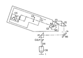
図1は本発明に係るアイポイント可変鏡筒の第1実施例を示す構成図である。この実施例では、試料面1からの光は無限遠補正対物レンズOBによって無限遠光束に変換され、アイポイント位置可変鏡筒と接眼レンズOCとによって観察される。アイポイント位置可変鏡筒は、対物レンズOB側から順に配置された、対物レンズOBからの光束を集光する第1レンズ群G1Lと、第1レンズ群G1Lからの光を90度水平方向へ観察者(或いは接眼レンズOC)から遠ざかる方向に向かって偏向させるプリズムP1と、プリズムP1からの光束を2回の反射によって90度偏向させて鉛直方向へ出射させる二つの偏向ミラーM1,M2と、偏向ミラーM2からの光束を観察者に向けて偏向させる回動可能な偏向ミラーM3を備え且つ第1レンズ群G1Lにより形成された中間像を平行光束に変換する第2の光学系G2と、前記中間像を再結像する第3の光学系G3と、この像を観察する接眼レンズOCとで構成されている。第1レンズ群G1LとプリズムP1と偏向ミラーM1,M2とは、第1の光学系G1を構成している。なお、ここではプリズム部を含む双眼部は図示省略されている。
回動可能な偏向ミラーM3は、偏向ミラーM2を出射した光束の光軸と第2の光学系G2の光軸とが交叉する点Pを通り偏向ミラーM2と第2の光学系G2の光軸を含む平面に垂直な軸の周りに回動し得るように構成されており、第2の光学系G2と第3の光学系G3と双眼部と接眼レンズOCは一体となって、上記点Pの周りに回動し得るように構成されている。
【0018】
実施例1は上記のように構成されているから、無限遠対物レンズOBからの光束は第1レンズ群G1Lで収束され、プリズムP1によって水平方向に偏向され、二つの偏向ミラーM1,M2によって鉛直方向へ偏向される。第1レンズ群G1Lによって偏向ミラーM1とM2の間に中間像IOが形成され、この中間像IOは第2の光学系G2によって平行光束に変換されて、第3の光学系G3によって接眼レンズOCの焦点位置Iに結像せしめられる。この場合、第2の光学系G2と第3の光学系G3と双眼部と接眼レンズOCとを一体的に、点Pを通り偏向ミラーM2からの出射光軸と第2の光学系G2の光軸とを含む面に垂直な軸の周りに回動させると、偏向ミラーM3によって観察時の俯角が調整され得る。そして、偏向ミラーM3が角度αで回転したときに、第2の光学系G2と第3の光学系G3と双眼部と接眼レンズOCを一体的に角度α/2だけ回転するように構成しておけば、観察の中心位置を変化させることなしに観察することが出来る。
【0019】
このように鏡筒内で中間像をつくる構成にすることで、従来例のように鏡筒内に中間像をつくらない構成のものに比べて鏡筒内での光学系の光路長を十分に長くすることが出来るので、4つの偏向部材の位置を適宜設定することにより点Pの位置を自由に選定することが可能となり、アイポイント位置Eと対物レンズOBの光軸間或いは準焦ハンドル3の中心間の距離やアイポイントの高さを自由に設定することが可能となる。つまり、アイポイントの高さと対物レンズ光軸からの水平距離を設定する際に、第1の光学系G1中の3つの偏向部材(プリズムP1及び偏向ミラーM1,M2)と偏向ミラーM3の位置を適宜設定することで、Pの位置を略自由に配置できるので、アイポイント位置Eを適切な位置に設定することが可能となる。
【0020】
また、第1の光学系G1中には、光束を偏向するための少なくとも3つの光学部材をもち、更に回動自在の光学部材をもつので、鏡筒内での反射回数は4回で、中間像を1回リレーするだけであるから、観察像は正立正像となる。また、偏向ミラーM3と第2の光学系G2と第3の光学系G3と双眼部を含む接眼レンズOCとが一体となって、点Pの周りに回動することで観察時の俯角を自由に調整することが出来るので、アイポイントの高さ位置を自由に変えることが出来ることになる。従って、従来のティルティング鏡筒に対して本実施例の構成を用いれば、アイポイントの位置を適切にすることが可能となる。更に、中間鏡筒ユニットなどを挿脱することにより、無限遠補正対物レンズOBと第1レンズ群G1Lとの間隔D0を変えることによっても、アイポイント位置Eの高さを変えることが出来る。
【0021】
実施例2
図2は本発明に係るアイポイント可変鏡筒の第2実施例を示す構成図である。この実施例は、第2の光学系G2と第3の光学系G3との間隔を伸縮自在に構成した点で、第1実施例とは異なる。従って、第1実施例と実質上同一の部材には同一符号が付されており、同一の構成部分及び作用については説明が省略されている。この実施例では、第3の光学系G3と双眼部と接眼レンズOCとが一体となって、第2の光学系G2の光軸方向に移動し、第2の光学系G2と第3の光学系G3との間隔D1を変えることが出来るようになっている。第2の光学系G2と第3の光学系G3の間はアフォーカルであるため、上記のようにして第3の光学系G3が移動しても、結像位置や倍率を変化させることなしに、アイポイントの位置Eを変化させることが出来る。従って、この実施例によれば、第1実施例と同様の操作によってアイポイント位置Eを変えることが出来るのに加えて、第3の光学系G3と双眼部と接眼レンズOCを観察者の体格に応じて一体的に移動させることによっても、アイポイント位置Eから対物レンズ光軸までと準焦ハンドル3までの水平距離及びアイポイントの高さを自由に調整することが可能となる。
【0022】
図3,4及び5は、第1の光学系G1の構成が互いに異なる、実施例2の変形例を夫々示している。即ち、図3においては、偏向部材がプリズムP1と偏向ミラーM1と偏向プリズムP2,P3と回動自在な偏向ミラーM2とで構成され、反射回数は6回で正立正像が観察されるようになっている。図4においては、偏向部材が偏向プリズムP1′と偏向ミラーM1,M2と回動自在な偏向ミラーM3とで構成され、反射回数は4回で正立正像が観察されるようになっている。図5においては、偏向部材がプリズムP1と偏向ミラーM1,M2と回動自在な偏向ミラーM3とで構成され、反射回数は4回で正立正像が観察されるようになっている。これらの各変形例は、第1実施例にも適用できることは云うまでもない。
【0023】
実施例3
図6は本発明に係るアイポイント可変鏡筒の第3実施例を示す構成図である。この実施例は、第3の光学系G3が第2の光学系G2側から順に配置された、一枚の正の屈折力をもつメニスカスレンズ群L31と、負の屈折力をもつレンズ群L32と一枚の正の屈折力をもつメニスカスレンズを含む正の屈折力をもつレンズ群L33とで構成されている。従って、その他の構成及び作用効果は基本的には実施例2と同様であるが、第3の光学系G3を正,負,正の三群構成にすることで、第2の光学系G2と第3の光学系G3との間隔が、第2の光学系の焦点距離F2と第3の光学系G3の焦点距離F3との和よりも短くなった場合でも、接眼レンズOCの焦点面での瞳位置を第3の光学系G3側に近づくようにさせることが可能となるので、光路長を短くして鏡筒をコンパクトに構成することができ、従って、一台の顕微鏡に対して従来の接眼レンズと共通に使用することが可能であり、或いは、接眼レンズでのケラレを抑えることが可能となる。
【0024】
即ち、第3の光学系を上記のように構成することにより、双眼部のプリズム部の光路長を確保しながら、後述のレンズデータにおいて示した近軸量から、対物レンズOBと第1の光学系G1との間隔D0および第2の光学系G2と第3の光学系G3との間隔D1の変化においても、対物レンズ側の入射瞳位置の変化および第3の光学系G3から接眼レンズOCまでを一体的に移動させた場合の射出瞳位置の変動を少なくし、第3の光学系G3から接眼レンズOCまでの各レンズの有効径を大きくすることなく、軸外光束の周辺光量の低下やケラレを抑えることが出来る。
【0025】
ここで、第1の光学系G1の焦点距離F1は180mm、第2の光学系の焦点距離F2は135.68mm、第3の光学系G3の焦点距離F3は135.68mm、全系の焦点距離Fは180mmであり、F1/F=1となるので、0.7≦F1/F≦1.4なる条件を満足し、更にF3/F=0.75であるので、0.5≦F3/F≦1なる条件も満足している。
【0026】
図7は実施例3の光路を直線に配置して示した光路図で、(a)はD0=60mmでD1=0の場合、(b)はD0=0でD1=45mmの場合、(c)はD0=170mmでD1=0の場合、(d)はD0=170mmでD1=45mmの場合の光学配置を夫々示している。後述の収差図からも分かるように、対物レンズOBと第1の光学系G1との間隔即ち中間鏡筒ユニットの間隔D0及び第2の光学系G2と第3の光学系G3との間隔D1を変化させた場合、何れの状態においても良好に収差性能が補正されているので、アイポイント位置Eが変わっても常に良好な光学性能で観察することが可能である。更に、偏向ミラーM3の回動により俯角を変化させてアイポイント高さを変えることで、より好適に観察者の体格に対応させることができ、無理のない姿勢での観察を可能にする。
【0027】
図6に示した光学配置において、D0=60mmの場合、俯角θは0度(水平)から25度(鎖線図示位置)までの範囲で変えることができ、アイポイント位置Eの高さは、鏡筒側胴付き位置8(図13参照)から110.4mm〜259.5mm、試料面1から鏡筒側胴付き位置8まで105mm、机上面2から試料面まで200mm、机上面2からアイポイント位置Eまでの高さH=410.4mm〜564.5mm、対物レンズ光軸からアイポイント位置Eまでの水平距離d=201.2mm〜265mmであり、D0=170mmの場合、机上面2から鏡筒側胴付き位置8まで475mm、机上面2からアイポイント位置Eまでの高さH=525.4mm〜674.5mmであった。
【0028】
このように、本実施例の鏡筒を通常の顕微鏡と組み合わせた場合、アイポイント位置Eを従来の鏡筒を用いた場合と略同じ位置から第2の光学系G2の光軸に沿って45mm移動させて対物レンズ光軸より離し、且つ俯角θを併せ変化させることにより、アイポイント位置Eの高さは机上面から約410mm〜565mmの範囲で変化させることができ、対物レンズ光軸からアイポイント位置Eまでの水平距離は約201mm〜265mmの範囲で変化させることが出来るので、従来の鏡筒に比べて背の低い小柄な人から背の高い大柄な人まで観察時の姿勢に無理がなく、楽な姿勢で観察することが出来るようになることが分かる。更に、中間鏡筒ユニット等を組み合わせてアイポイント位置Eの高さを更に110mmまで上げることにより、最大のアイポイント高さは675mmとなる。従って、従来のティルティング鏡筒のアイポイント位置付近から、アイポイント位置の高さと対物レンズ光軸からの水平距離とを広げることができ、大柄な体格の人にも対応できるようにすることが可能である。
【0029】
また、鏡筒内での光学系の構成は、光路長を同一にしておけば図3,図4及び図5に示した構成のもにしても良い。本実施例の構成では、第1の光学系G1の焦点距離F1が全系の焦点距離Fと一致しているので、第1の光学系G1と第2の光学系G2間でプリズムなどの光路分割素子を光路に対して挿脱可能に構成することにより、写真光路を設けることも可能である。また、図6において偏向ミラーM1を光路に対して挿脱可能に構成するか、或いはこの偏向ミラーをハーフミラー等で構成することにより、中間像を写真光路側へ導くようにすることも出来る。
【0030】
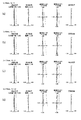
以下に本実施例のレンズデータと鏡筒の光学的な近軸量を示す。なお、図8は対物レンズOBと第1の光学系G1との間隔D0と第2の光学系G2と第3の光学系G3との間隔D1が変化した場合の、本実施例における接眼レンズOCの焦点面での収差性能を示しており、(a),(b),(c),(d)は図7の(a),(b),(c),(d)に夫々対応している。
F1=180mm

実施例4
本実施例は、実施例3と同様の光学配置(図6参照)であるが、第1の光学系G1の焦点距離F1が全系の焦点距離Fよりも長くなるように構成されている点で、第3実施例とは異なる。この実施例では、第1の光学系G1の焦点距離F1は215mm、第2の実施例の焦点距離F2は115.4mm、第3の光学系G3の焦点距離F3は96.62mm、全系の焦点距離は180mmであって、F1/F=1.19となるので、0.7≦F1/F≦1.4なる条件を満足し、更にF3/F=0.54であるので、0.5≦F3/F≦1なる条件も満足している。
【0032】
図9は本実施例の光路を直線に配置して示した光路図で、(a)はD0=60mmでD1=0の場合、(b)はD0=60mmでD1=45mmの場合、(c)はD0=170mmでD1=0の場合、(d)はD0=170mmでD1=45mmの場合の光学配置を夫々示している。図10は、D0とD1が変化した場合の本実施例における接眼レンズOCの焦点面での収差性能を示しており、(a),(b),(c),(d)は図9の(a),(b),(c),(d)に夫々対応している。
図10から明らかなように、本実施例においても、実施例3の場合と同様に、D0とD1を変化させた場合でも光学性能が良好に補正されており、システム性にも優れている。また、鏡筒光学系全体の光路長は、本実施例の下記レンズデータから明らかなように実施例3と略同じであり、本実施例の場合も実施例3と同様のレイアウト構成にすることにより、様々な身長の人に無理のない観察姿勢をとることを可能ならしめる。なお、本実施例においても、図3,図4及び図5に示した如きレイアウトを採用し得ることは云うまでもない。
【0033】
以下に本実施例のレンズデータと鏡筒の光学的な近軸量を示す。
F1=215mm
実施例5
本実施例は、実施例3と同様の光学配置(図6参照)であるが、第1の光学系G1の焦点距離F1が全系の焦点距離Fよりも短くなるように構成されている点で、実施例3及び4の何れとも異なる。本実施例では、第1の光学系G1の焦点距離F1は160mm、第2の光学系の焦点距離F2は153.16mm、第3の光学系G3の焦点距離F3は172.3mm、全系の焦点距離Fは180mmであって、F1/F=0.89となるので、0.7≦F1/F≦1.4なる条件を満足し、更にF3/F=0.957であるので、0.5≦F3/F≦1なる条件も満足している。
【0035】
図11は本実施例の光路を直線に配置して示した光路図で、(a)はD0=60mmでD1=0の場合、(b)はD0=60mmでD1=45mmの場合、(c)はD0=170mmでD1=0の場合、(d)はD0=170mmでD1=45mmの場合の光学配置を夫々示している。図12は、D0とD1が変化した場合の、本実施例における接眼レンズOCの焦点面での収差性能を示しており、(a),(b),(c),(d)は図11の(a),(b),(c),(d)に夫々対応している。この実施例においても、実施例3の場合と同様に、D0とD1を変化させた場合でも光学性能が良好に補正されており、システム性にも優れている。また、鏡筒光学系全体の光路長は、本実施例の下記レンズデータから明らかなように実施例3と略同じであり、本実施例の場合も実施例3と同様のレイアウト構成にすることにより、様々な身長の人に無理のない観察姿勢をとることを可能にする。なお、本実施例においても、図3,図4,図5に示した如きレイアウトを採用し得ることは云うまでもない。
【0036】
以下に本実施例のレンズデータと鏡筒の光学的な近軸量を示す。
F1=160mm
【0038】
【発明の効果】
上述の如く本発明によれば、従来の鏡筒やティルティング鏡筒に比べて、アイポイント位置を大きく変化させることができて、背の高い人から小柄な体格の人に至るまで常に無理のない姿勢で観察することが可能であり、疲労の低減に効果的で且つ中間鏡筒ユニットなどのシステム性に優れたアイポイント位置可変鏡筒と顕微鏡を提供することが出来る。
【図面の簡単な説明】
【図1】本発明に係るアイポイント可変鏡筒の第1実施例を示す構成図である。
【図2】本発明に係るアイポイント可変鏡筒の第2実施例を示す構成図である。
【図3】第2実施例の一変形例を示す構成図である。
【図4】第2実施例の他の変形例を示す構成図である。
【図5】第2実施例の更に他の変形例を示す構成図である。
【図6】本発明に係るアイポイント可変鏡筒の第3実施例を示す構成図である。
【図7】第3実施例の光路を直線に配置して示した光路図で、(a)はD0=60mmでD1=0の場合、(b)はD0=0でD1=45mmの場合、(c)はD0=170mmでD1=0の場合、(d)はD0=170mmでD1=45mmの場合を夫々示している。
【図8】第3実施例における接眼レンズの焦点面での収差性能を示した収差図で、(a),(b),(c),(d)は図7の(a),(b),(c),(d)に夫々対応している。
【図9】本発明に係るアイポイント可変鏡筒の第4実施例の光路を直線に配置して示した光路図で、(a)はD0=60mmでD1=0の場合、(b)はD0=60mmでDに45mmの場合、(c)はD0=170mmでD1=0の場合、(d)はD0=170mmでD1=45mmの場合を夫々示している。
【図10】第4実施例における接眼レンズの焦点面での収差性能を示した収差図で、(a),(b),(c),(d)は図9の(a),(b),(c),(d)に夫々対応している。
【図11】本発明に係るアイポイント可変鏡筒の第5実施例の光路を直線に配置して示した光路図で、(a)はD0=60mmでD1=0の場合、(b)はD0=60mmでD1=45mmの場合、(c)はD0=170mmでD1=0の場合、(d)はD0=170mmでDに45mmの場合を夫々示している。
【図12】第5実施例における接眼レンズの焦点面での収差性能を示した収差図で、(a),(b),(c),(d)は図11の(a),(b),(c),(d)に夫々対応している。
【図13】従来の一般的な顕微鏡の概略側面図である。
【符号の説明】
1 試料面
2 机上面
3 準焦ハンドル
4 鏡筒
5 顕微鏡本体
6 コンデンサーレンズ
7 ステージハンドル
8 鏡筒側胴付き位置
OB 対物レンズ
OC 接眼レンズ
E アイポイント位置
H 机上面からアイポイント位置までの高さ
θ 観察時の俯角
d 対物レンズ光軸からアイポイント位置までの水平距離
G1 第1の光学系
G1L 第1レンズ群
D0 対物レンズと第1レンズ群の間隔
P1,P1′,P2,P3 プリズム
M1,M2,M3 ミラー
G2 第2の光学系
G3 第3の光学系
D1 第2の光学系と第3の光学系の間隔
L31 第3の光学系の第1レンズ群
L32 第3の光学系の第2レンズ群
L33 第3の光学系の第3レンズ群
P 光軸の交叉点[0001]
BACKGROUND OF THE INVENTION
The present invention relates to a lens barrel having a variable eyepoint position and a microscope using the same.
[0002]
[Prior art]
There have been various proposals in the past for the lens barrel used for microscope observation to make the eye position looking into the eyepiece lens (eye point) easy to observe and easy to take. Has been made.
For example, Japanese Patent Application Laid-Open No. 4-166907 proposes a tilting lens barrel having a mechanism for adjusting a depression angle, which is an angle at which a binocular eyepiece is viewed. Here, the height and position of the eye point are changed by changing the depression angle.
Japanese Patent Laid-Open No. 8-278448 proposes to lower the position of the eye point by deflecting the light beam from the objective lens by a deflecting member. This is intended to observe in an easy posture by lowering the eye point position in advance.
Japanese Patent Application Laid-Open No. 10-142473 proposes a lens barrel including a tilting mechanism that changes the depression angle and a mechanism that moves the tilting mechanism along the observation optical axis. This is intended to change the height of the eye point position and the horizontal distance from the optical axis of the objective lens to the position of the eye of the observer.
Further, in Japanese Patent Laid-Open No. 9-73031, in a microscope having an optical system in which the objective lens and the imaging lens of the movable lens barrel are afocal, in the afocal light beam between the objective lens and the imaging lens. The light beam is deflected in the horizontal direction by the first deflecting member, further deflected by 90 degrees by the second deflecting member, and incident on the imaging lens, and between the first deflecting member and the second deflecting member. A guide is provided between the first deflection member and the movable barrel so as to change the eye point position.
[0003]
[Problems to be solved by the invention]
In microscopic observation, it is very important that the observer can observe in a comfortable posture. When many samples and specimens are inspected for a long time, fatigue and oversight of the inspection are prevented. This is an important point. Although FIG. 13 shows the external dimensions of a general microscope, in order to reduce the fatigue of the observer, when a tall large person and a short small person observe using the same microscope, In general, 1) the height H from the desk surface 2 to the eye point position E of the eyepiece lens OC, 2) the angle (angle of depression) θ when looking into the eyepiece lens OC, and 3) from the optical axis of the objective lens It is important that the three horizontal distances d to the eye point position E of the eyepiece have appropriate values. In order to enable observation with a comfortable posture for a long time, when the hand is put on the semi-focus handle 3 regardless of the body shape, the eye point position E of the eyepiece is brought into the eye position with a comfortable posture. It is necessary to have. In a general microscope, the height from the desk top surface 2 to the
[0004]
When the tilting lens barrel proposed in Japanese Utility Model Laid-Open No. 4-124218 is combined with this microscope, the height of the eye point position E is about 400 mm at the lowest combination from the desk surface 2. Further, in the case of a tilting lens barrel that can change the depression angle θ, the height from the desk top surface 2 varies in the range of about 400 mm to 500 mm. Further, the distance from the optical axis position of the objective lens OB to the center position of the semi-focus handle 3 is about 100 mm. In a general lens barrel, the eye point position E is about 195 mm in the horizontal direction from the optical axis of the objective lens OB. is there. In the tilting lens barrel that can change the depression angle θ, the horizontal distance varies in the range of about 140 mm to 195 mm.
[0005]
In the case of the tilting barrel that simply changes the depression angle, the horizontal distance from the optical axis of the objective lens OB to the eye point position E changes only slightly when the depression angle θ is changed. When the angle from the horizontal is increased, there is a disadvantage that the distance in the horizontal direction is shortened. This has the problem of making it impossible to observe in a reasonable posture regardless of the body shape of the observer. For example, for a tall and large foreigner, the distance in the horizontal direction from the optical axis of the objective lens is necessary more than that of a small woman, and the eye point height is also necessary. For example, for a person with a height of 1580 mm, the optimum eye point height is about 430 mm from the desk top surface 2, and for a person with a height of 1840 mm, the height from the floor to the desk top surface 2 is 70 cm, and the height of the chair at the time of observation is When adjusted, the minimum eye point height required is about 510 mm from the desk top surface 2, and the eye point height that is said to be optimal is about 600 mm from the desk top surface 2. Even at this eyepoint height, the
[0006]
In the lens barrel proposed in Japanese Patent Laid-Open No. 10-142473, the depression angle and the eye point position can be changed independently. However, in the lens configuration proposed in Japanese Patent Laid-Open No. 10-142473, the light beam from the objective lens is relayed to the focal plane of the eyepiece without forming an image, so that the optical path length in the lens barrel is sufficient. Can not take long. Therefore, it is possible to adopt a configuration in which the horizontal distance from the objective lens to the eye point position of the eyepiece is substantially separated and the eye point height is also greatly changed to match the various physiques of the observer described above. Can not.
Also, if the eyepoint position is moved away by increasing the movement distance of the afocal part, the effective diameter of the prism part of the lens or binocular part increases, and the aberration performance of off-axis light flux deteriorates, or the exit pupil position changes. There is a drawback that vignetting occurs in the eyepiece when it changes greatly.
Further, when the afocal magnification of the first optical system and the second optical system is increased, the focal length of the third optical system is increased, and the eye point position is separated, the second optical system is emitted. Since the angle of the off-axis chief ray becomes large, the effective diameter after the third optical system increases as a result, and the peripheral aberration performance and the exit pupil position are not matched.
Further, when the epi-illumination unit, the optical path dividing unit, and the unit for raising the eye point position are arranged, the diameter of the light beam from the objective lens becomes large, and the first optical system, the second optical system, and the tilt Since the effective diameter of the tilting mirror increases and the amount of peripheral light is insufficient and vignetting occurs, it is difficult to increase the length of the intermediate lens barrel. If the effective diameter of these optical systems is increased, the lens is limited. There was a drawback that it could not be placed in the space.
That is, in the lens barrel proposed in Japanese Patent Application Laid-Open No. 10-142473, it is difficult to sufficiently increase the horizontal distance from the optical axis of the objective lens to the eye point position and the eye point height. Since the moving distance of the optical system is limited to about 30 mm, it is difficult to realize an optimal observation posture especially for tall and large people according to the various physiques of the observer. Specific numerical values such as the height of the eye point position and the horizontal distance from the optical axis of the objective lens to the eye point position are not disclosed, and the superiority over the conventional lens barrel is not clear.
[0007]
Similarly, the one proposed in Japanese Patent Laid-Open No. 9-73031 also has a limit in the amount of movement of the lens group when changing the length of the afocal light beam portion, and the eye is so large that it can cope with the physiques of various observers. The point position cannot be changed.
[0008]
The present invention has been made in view of the above-described problems of the prior art, and the object of the present invention is to provide a posture with less fatigue to a person of any physique and without any unreasonable observation posture. The horizontal distance from the optical axis of the objective lens to the eye point position, the height of the eye point, and the angle of depression at the time of observation can be changed so that it can be observed. An eyepoint position variable lens barrel and a microscope using the same are provided.
[0009]
[Means for Solving the Problems]
In order to achieve the above object, a lens barrel according to the present invention includes, in order from the light incident side, a first optical system and a second light beam that converts a light beam emitted from the first optical system into a parallel light beam. An optical system, and a third optical system that guides the parallel light beam emitted from the second optical system to the eyepiece, wherein the first optical system deflects the light beam and a lens group that forms an intermediate image At least three light deflecting members, and the second optical system has a lens group and a light deflecting member;The at least three lightsAmong the deflecting members, the light is emitted from the light deflecting member disposed closest to the second optical system.TheThe optical axis of the light beam is the first optical axis and is emitted from the second optical system.TheWhen the optical axis of the parallel light beam is the second optical axis, the second optical systemSaidThe light deflecting member is disposed so as to rotate about an axis perpendicular to the first optical axis and the second optical axis.The third optical system is configured such that an interval between the third optical system and the second optical system can be changed, and the third optical system is movable in the optical axis direction of the second optical system.It is characterized by that.
According to this configuration, the incident light beam forms an intermediate image by the first optical system, is re-imaged on the focal plane of the eyepiece by the second optical system and the third optical system, and is observed.
In order to observe an image without vignetting with the eyepiece, it is necessary to make the entrance pupil position of the eyepiece and the exit pupil position of the lens barrel substantially coincide with each other, and the second optical system and the third optical system are respectively connected to the eyepiece. In the case of one group, the distance between the second optical system and the third optical system is approximately F2 + F3, where F2 is the focal length of the second optical system and F3 is the focal length of the third optical system. A certain interval is required. Moreover, since the intermediate image by the first optical system is converted into a parallel light beam by the second optical system, when the first optical system is configured by a single lens, the distance between the first optical system and the second optical system is When the focal length of the first optical system is F1, F1 + F2.
Therefore, by constructing the intermediate image in the lens barrel, the optical path length of the optical system in the lens barrel can be made sufficiently long compared to the configuration not creating the intermediate image. The degree of freedom for setting the position of the eye point is increased depending on the layout of the optical path.
Further, since the first optical system has at least three optical members for deflecting the light beam and further has an optical member configured to be rotatable, the number of reflections due to the deflection of the light beam in the lens barrel. Becomes four times, and it is an observation of an erect image. In addition, the light deflecting member of the second optical system, the second optical system, the third optical system, and the eyepiece are integrated and rotated around an axis perpendicular to the optical axis of the second optical system. By moving, it becomes possible to adjust the depression angle during observation.
Further, the eye point position can be changed by moving the third optical system and the eyepiece lens integrally in the optical axis direction of the third optical system, and the light deflection member of the second optical system. By rotating the lens, it becomes possible to change the depression angle at which the eyepiece lens is viewed during observation, and the height of the eye point position and the position from the optical axis of the objective lens can be changed.
[0011]
Further, according to the present invention, when the light deflection member of the second optical system is rotated by the angle α, the second optical system, the third optical system, and the eyepiece are integrally rotated by an angle α / 2. It comes to move.
With this configuration, the optical axis emitted from the optical deflection member of the second optical system and the optical axis of the eyepiece lens always coincide with each other. Makes it possible to provide
[0013]
According to the invention, the third optical system includes, from the second optical system side, a first lens group having a positive refractive power, a second lens group having a negative refractive power, and a positive It is composed of a third lens group having refractive power.
According to this configuration, the distance between the second optical system and the third optical system can be shortened compared to the case where the third optical system is configured with a single lens (including a cemented lens). Since the pupil position of the eyepiece can be made closer to the third optical system side, the conventional eyepiece can be used in common, or vignetting can be suppressed in the eyepiece. .
As will be described later in Example 1, when the third optical system is composed of a group of cemented lenses, the focal plane of the eyepiece lens is short if the distance between the second optical system and the third optical system is short. Since the pupil position of the lens approaches the eyepiece lens side, there are limitations on the eyepiece such that the effective diameter of the eyepiece increases and vignetting occurs in the vicinity. Further, in order to make the pupil position dive to the third optical system side, it is necessary to increase the distance between the second lens system and the third lens system. The structure itself may become large. In other words, by configuring the third optical system as described above, the position of the entrance pupil on the objective lens side by the combination of the intermediate lens barrel unit while ensuring the optical path length of the binocular portion that is the prism portion between the pair of eyepieces And the variation of the exit pupil position when moving from the third optical system to the eyepiece lens as a unit, and effectively increasing the effective diameter of each lens from the third optical system to the eyepiece lens. Therefore, it is possible to suppress a decrease in the amount of light around the off-axis light beam and vignetting. In addition, since the entire optical path length can be shortened, the entire configuration of the lens barrel can be made compact.
[0014]
According to the invention, the first lens group includes at least one positive meniscus lens having a concave surface facing the second lens group, and the third lens group includes the first lens group therein. At least one positive meniscus lens having a concave surface facing the two lens group side is provided.
With this configuration, the occurrence of aberration due to off-axis rays can be further suppressed, and the change in the entrance pupil position of the objective lens by the combination of the objective lens and the intermediate lens barrel unit and the third optical system to the eyepiece lens are integrated. It is possible to maintain good off-axis aberration performance due to variations in the exit pupil position when moved.
[0015]
The lens barrel according to the present invention is 0.7 when the focal length of the first optical system is F1, and the focal length of the entire system from the first optical system to the third optical system is F. ≦ F1 / F ≦ 1.4 is satisfied.
According to this configuration, the horizontal distance from the optical axis of the objective lens to the eye point position can be made compact without increasing the lens diameter and without unnecessarily increasing the optical path length in the lens barrel. And the height of the eye point position can be set higher than that of the conventional lens barrel. Furthermore, by moving integrally from the third optical system to the eyepiece along the optical axis of the second optical system, the horizontal distance from the objective lens optical axis to the eye point position is greatly changed and the depression angle is increased. By changing it, it is possible to make it possible to take an ideal observation posture for the eye point position.
When F1 / F becomes smaller than the lower limit of the above conditional expression, when the value of the focal length F2 of the second optical system is larger than F1, the focal length F3 (= (F2 / F1) of the third optical system. ) × F) is longer than F, so the length from the third lens system to the eyepiece is increased, and the eye point position is too far from the objective lens optical axis, so that an appropriate observation posture cannot be obtained. If the value of F2 is smaller than F1, the optical path length can be shortened, but aberration performance cannot be corrected well, or a field lens is provided at the intermediate image position to adjust the pupil position. As a result, the number of lenses increases, resulting in an increase in product cost.
Further, when an intermediate lens barrel unit is inserted between the infinity-corrected objective lens and the lens barrel to increase the distance between them, vignetting and off-axis aberration performance are deteriorated, which is not preferable in terms of the system.
Further, if F1 / F increases beyond the upper limit of the conditional expression, when the value of F2 is smaller than F1, F3 is also shortened, so that the optical path length of the binocular portion of the prism portion cannot be obtained, or third Therefore, it is necessary to increase the lens diameter of the optical system and the prism of the binocular unit, and it becomes impossible to share the components of the conventional binocular unit, resulting in an increase in product cost. When the distance between the infinity-corrected objective lens and the lens barrel is shortened, the pupil position is not appropriate, and vignetting and peripheral aberration performance are deteriorated.
[0016]
The lens barrel according to the present invention is configured to satisfy the condition of 0.5 ≦ F3 / F ≦ 1.
According to this configuration, the aberration can be corrected satisfactorily, and the pupil position when the third optical system is moved integrally from the eyepiece lens or when the intermediate lens barrel unit is inserted between the objective lens and the lens barrel. There is little vignetting of the eyepiece due to changes and a decrease in the amount of peripheral light, it is possible to correct aberrations satisfactorily in any state, the optical path layout in the lens barrel can be made compact, and the eyepoint position can This is preferable because it can be largely separated from the same position as the lens barrel.
When F3 / F becomes smaller than the lower limit of the above conditional expression, the optical path length of the lens barrel becomes very large and the lens barrel becomes large, or F3 becomes short and from the third optical system to the eyepiece. It becomes impossible to secure the optical path length. In addition, the pupil position cannot be made substantially coincident with the entrance pupil position of the eyepiece, and vignetting and off-axis aberration performance are deteriorated.
If F3 / F exceeds the upper limit of the above conditional expression, F3 becomes longer and the optical path length from the third optical system to the eyepiece becomes longer, so that the eye point position moves away from the optical axis of the objective lens. Not only is this too long, but the entire optical path length becomes longer and the lens barrel becomes larger, which is not preferable. Further, the vignetting and the off-axis aberration performance are deteriorated in the same manner as when the pupil position cannot be made substantially coincident with the entrance pupil position of the eyepiece and F3 / F becomes smaller than the lower limit.
[0017]
DETAILED DESCRIPTION OF THE INVENTION
Hereinafter, embodiments of the present invention will be described based on the illustrated examples with reference to FIG. 13 used in the prior art.
Example 1
FIG. 1 is a block diagram showing a first embodiment of an eyepoint variable lens barrel according to the present invention. In this embodiment, the light from the
The rotatable deflection mirror M3 passes through the point P where the optical axis of the light beam emitted from the deflection mirror M2 and the optical axis of the second optical system G2 intersect, and the optical axes of the deflection mirror M2 and the second optical system G2. The second optical system G2, the third optical system G3, the binocular unit, and the eyepiece OC are integrated to form the point P described above. It is comprised so that it can rotate around.
[0018]
Since the first embodiment is configured as described above, the light beam from the infinity objective lens OB is converged by the first lens group G1L, deflected in the horizontal direction by the prism P1, and vertical by the two deflecting mirrors M1 and M2. Deflected in the direction. An intermediate image IO is formed between the deflection mirrors M1 and M2 by the first lens group G1L. The intermediate image IO is converted into a parallel light beam by the second optical system G2, and the eyepiece OC is converted by the third optical system G3. The image is formed at the focal position I. In this case, the second optical system G2, the third optical system G3, the binocular unit, and the eyepiece lens OC are integrated with each other through the point P and the optical axis emitted from the deflection mirror M2 and the light of the second optical system G2. When it is rotated around an axis perpendicular to the plane including the axis, the depression angle during observation can be adjusted by the deflection mirror M3. The second optical system G2, the third optical system G3, the binocular unit, and the eyepiece OC are integrally rotated by an angle α / 2 when the deflection mirror M3 is rotated at an angle α. If so, it is possible to observe without changing the central position of the observation.
[0019]
By constructing the intermediate image in the lens barrel in this way, the optical path length of the optical system in the lens barrel is sufficiently longer than in the conventional configuration in which the intermediate image is not created in the lens barrel. Since the length can be made longer, the position of the point P can be freely selected by appropriately setting the positions of the four deflecting members, and between the eye point position E and the optical axis of the objective lens OB or the semi-focus handle 3. It is possible to freely set the distance between the centers and the height of the eye point. That is, when setting the height of the eye point and the horizontal distance from the optical axis of the objective lens, the positions of the three deflecting members (the prism P1 and the deflecting mirrors M1 and M2) and the deflecting mirror M3 in the first optical system G1 are set. By appropriately setting, the position of P can be arranged almost freely, so that the eye point position E can be set to an appropriate position.
[0020]
In addition, the first optical system G1 has at least three optical members for deflecting the light beam, and further has a rotatable optical member. Since the image is relayed only once, the observed image is an erect image. In addition, the deflection mirror M3, the second optical system G2, the third optical system G3, and the eyepiece OC including the binocular portion are integrated and rotated around the point P, so that the depression angle during observation can be freely set. It is possible to freely change the height position of the eye point. Therefore, if the configuration of the present embodiment is used for the conventional tilting lens barrel, the position of the eye point can be made appropriate. Further, the height of the eye point position E can be changed by changing the distance D0 between the infinity corrected objective lens OB and the first lens group G1L by inserting or removing the intermediate lens barrel unit or the like.
[0021]
Example 2
FIG. 2 is a block diagram showing a second embodiment of the eyepoint variable lens barrel according to the present invention. This embodiment is different from the first embodiment in that the distance between the second optical system G2 and the third optical system G3 is configured to be extendable. Accordingly, members that are substantially the same as those in the first embodiment are given the same reference numerals, and descriptions of the same components and operations are omitted. In this embodiment, the third optical system G3, the binocular unit, and the eyepiece OC are integrated and moved in the optical axis direction of the second optical system G2, and the second optical system G2 and the third optical system are moved. The distance D1 from the system G3 can be changed. Since the distance between the second optical system G2 and the third optical system G3 is afocal, even if the third optical system G3 moves as described above, the imaging position and magnification are not changed. The position E of the eye point can be changed. Therefore, according to this embodiment, the eye point position E can be changed by the same operation as in the first embodiment, and in addition, the third optical system G3, the binocular portion, and the eyepiece OC are made up of the observer's physique. Accordingly, the horizontal distance from the eye point position E to the objective lens optical axis and the semi-focus handle 3 and the height of the eye point can be freely adjusted.
[0022]
3, 4 and 5 show modifications of the second embodiment in which the configuration of the first optical system G1 is different from each other. That is, in FIG. 3, the deflecting member is constituted by the prism P1, the deflecting mirror M1, the deflecting prisms P2 and P3, and the rotatable deflecting mirror M2, so that an erect image is observed with the number of reflections being six. It has become. In FIG. 4, the deflecting member is composed of a deflecting prism P1 ', deflecting mirrors M1 and M2, and a rotatable deflecting mirror M3, and an erect image is observed with four reflections. In FIG. 5, the deflecting member is composed of a prism P1, deflecting mirrors M1 and M2, and a rotatable deflecting mirror M3, and an erect image is observed with four reflections. Needless to say, each of these modifications can also be applied to the first embodiment.
[0023]
Example 3
FIG. 6 is a block diagram showing a third embodiment of the eyepoint variable lens barrel according to the present invention. In this embodiment, a single meniscus lens group L31 having a positive refractive power, a lens group L32 having a negative refractive power, in which a third optical system G3 is disposed in order from the second optical system G2 side. The lens unit L33 includes a lens unit L33 having a positive refractive power including a single meniscus lens having a positive refractive power. Accordingly, the other configurations and operational effects are basically the same as those of the second embodiment, but the third optical system G3 has a three-group configuration of positive, negative, and positive so that the second optical system G2 Even when the distance from the third optical system G3 is shorter than the sum of the focal length F2 of the second optical system and the focal length F3 of the third optical system G3, the distance from the focal plane of the eyepiece lens OC is reduced. Since the pupil position can be made closer to the third optical system G3 side, the optical path length can be shortened and the lens barrel can be configured compactly. It can be used in common with the eyepiece lens, or it is possible to suppress vignetting in the eyepiece lens.
[0024]
That is, by configuring the third optical system as described above, the objective lens OB and the first optical system can be obtained from the paraxial amount shown in the lens data described later while ensuring the optical path length of the binocular prism portion. Even in the change of the distance D0 between the system G1 and the distance D1 between the second optical system G2 and the third optical system G3, the change in the entrance pupil position on the objective lens side and the third optical system G3 to the eyepiece OC. When the lens is moved integrally, the variation in the exit pupil position is reduced, and the peripheral light amount of the off-axis light beam is reduced without increasing the effective diameter of each lens from the third optical system G3 to the eyepiece lens OC. Vignetting can be suppressed.
[0025]
Here, the focal length F1 of the first optical system G1 is 180 mm, the focal length F2 of the second optical system is 135.68 mm, the focal length F3 of the third optical system G3 is 135.68 mm, and the focal length of the entire system. Since F is 180 mm and F1 / F = 1, the condition of 0.7 ≦ F1 / F ≦ 1.4 is satisfied. Further, since F3 / F = 0.75, 0.5 ≦ F3 / The condition of F ≦ 1 is also satisfied.
[0026]
7A and 7B are optical path diagrams showing the optical paths of Example 3 arranged in a straight line. FIG. 7A shows a case where D0 = 60 mm and D1 = 0. FIG. 7B shows a case where D0 = 0 and D1 = 45 mm. ) Shows the optical arrangement when D0 = 170 mm and D1 = 0, and (d) shows the optical arrangement when D0 = 170 mm and D1 = 45 mm. As can be seen from the aberration diagrams described later, the distance between the objective lens OB and the first optical system G1, that is, the distance D0 between the intermediate lens barrel units and the distance D1 between the second optical system G2 and the third optical system G3 are set. When changed, the aberration performance is corrected well in any state, so that it is possible to always observe with good optical performance even if the eye point position E changes. Furthermore, by changing the depression angle by rotating the deflection mirror M3 to change the eye point height, it is possible to more appropriately correspond to the physique of the observer, and observation with a reasonable posture is possible.
[0027]
In the optical arrangement shown in FIG. 6, when D0 = 60 mm, the depression angle θ can be changed in the range from 0 degree (horizontal) to 25 degrees (the position shown by the chain line), and the height of the eye point position E 110.4 mm to 259.5 mm from
[0028]
As described above, when the lens barrel of this embodiment is combined with a normal microscope, the eye point position E is 45 mm along the optical axis of the second optical system G2 from substantially the same position as when the conventional lens barrel is used. By moving away from the objective lens optical axis and changing the depression angle θ, the height of the eye point position E can be changed within a range of about 410 mm to 565 mm from the desk top surface. Since the horizontal distance to point position E can be changed in the range of about 201mm to 265mm, it is difficult to observe the posture from a small person who is short compared to the conventional lens barrel to a large person who is tall. It can be seen that it becomes possible to observe with a comfortable posture. Furthermore, the maximum eye point height becomes 675 mm by further increasing the height of the eye point position E to 110 mm by combining an intermediate lens barrel unit and the like. Therefore, from the vicinity of the eye point position of the conventional tilting lens barrel, the height of the eye point position and the horizontal distance from the optical axis of the objective lens can be widened, so that a person with a large physique can be accommodated. Is possible.
[0029]
Further, the configuration of the optical system in the lens barrel may be the configuration shown in FIGS. 3, 4 and 5 as long as the optical path length is the same. In the configuration of this embodiment, since the focal length F1 of the first optical system G1 matches the focal length F of the entire system, an optical path such as a prism between the first optical system G1 and the second optical system G2. It is also possible to provide a photographic optical path by configuring the dividing element so that it can be inserted into and removed from the optical path. In FIG. 6, the deflection mirror M1 can be inserted into and removed from the optical path, or the deflection mirror can be constituted by a half mirror or the like so that the intermediate image can be guided to the photographic optical path side.
[0030]
The lens data of this embodiment and the optical paraxial amount of the lens barrel are shown below. FIG. 8 shows the eyepiece OC in this embodiment when the distance D0 between the objective lens OB and the first optical system G1 and the distance D1 between the second optical system G2 and the third optical system G3 are changed. (A), (b), (c), and (d) correspond to (a), (b), (c), and (d) of FIG. 7, respectively. ing.
F1 = 180mm
Example 4
The present embodiment has the same optical arrangement as that of the third embodiment (see FIG. 6), but is configured such that the focal length F1 of the first optical system G1 is longer than the focal length F of the entire system. This is different from the third embodiment. In this embodiment, the focal length F1 of the first optical system G1 is 215 mm, the focal length F2 of the second embodiment is 115.4 mm, and the focal length F3 of the third optical system G3 is 96.62 mm. Since the focal length is 180 mm and F1 / F = 1.19, the condition of 0.7 ≦ F1 / F ≦ 1.4 is satisfied, and further F3 / F = 0.54. The condition of 5 ≦ F3 / F ≦ 1 is also satisfied.
[0032]
FIG. 9 is an optical path diagram showing the optical paths of this embodiment arranged in a straight line. FIG. 9A shows a case where D0 = 60 mm and D1 = 0. FIG. 9B shows a case where D0 = 60 mm and D1 = 45 mm. ) Shows the optical arrangement when D0 = 170 mm and D1 = 0, and (d) shows the optical arrangement when D0 = 170 mm and D1 = 45 mm. FIG. 10 shows the aberration performance at the focal plane of the eyepiece OC in the present example when D0 and D1 change. (A), (b), (c), and (d) of FIG. This corresponds to (a), (b), (c), and (d), respectively.
As is apparent from FIG. 10, in this embodiment, as in the case of the third embodiment, even when D0 and D1 are changed, the optical performance is corrected well, and the system performance is excellent. The optical path length of the entire lens barrel optical system is substantially the same as that of the third embodiment as is apparent from the following lens data of the present embodiment. In this embodiment, the layout configuration is the same as that of the third embodiment. This makes it possible for people of various heights to take reasonable observation postures. It goes without saying that the layouts shown in FIGS. 3, 4 and 5 can also be adopted in this embodiment.
[0033]
The lens data of this embodiment and the optical paraxial amount of the lens barrel are shown below.
F1 = 215mm
Example 5
The present embodiment has the same optical arrangement as that of the third embodiment (see FIG. 6), but is configured such that the focal length F1 of the first optical system G1 is shorter than the focal length F of the entire system. This is different from any of the third and fourth embodiments. In the present embodiment, the focal length F1 of the first optical system G1 is 160 mm, the focal length F2 of the second optical system is 153.36 mm, the focal length F3 of the third optical system G3 is 172.3 mm, Since the focal length F is 180 mm and F1 / F = 0.89, the condition 0.7 ≦ F1 / F ≦ 1.4 is satisfied, and further F3 / F = 0.957, so 0 .5 ≦ F3 / F ≦ 1 is also satisfied.
[0035]
FIG. 11 is an optical path diagram showing the optical paths of this embodiment arranged in a straight line. FIG. 11A shows a case where D0 = 60 mm and D1 = 0, and FIG. 11B shows a case where D0 = 60 mm and D1 = 45 mm. ) Shows the optical arrangement when D0 = 170 mm and D1 = 0, and (d) shows the optical arrangement when D0 = 170 mm and D1 = 45 mm. FIG. 12 shows the aberration performance on the focal plane of the eyepiece OC in the present example when D0 and D1 change. FIGS. 11A, 11B, 11C, and 11D show the aberration performance on the focal plane. (A), (b), (c), and (d) respectively. In this embodiment, as in the case of the third embodiment, even when D0 and D1 are changed, the optical performance is corrected well, and the system performance is excellent. The optical path length of the entire lens barrel optical system is substantially the same as that of the third embodiment as is apparent from the following lens data of the present embodiment. In this embodiment, the layout configuration is the same as that of the third embodiment. This makes it possible to take a comfortable observation posture for people of various heights. In this embodiment, it is needless to say that the layouts shown in FIGS. 3, 4, and 5 can be adopted.
[0036]
The lens data of this embodiment and the optical paraxial amount of the lens barrel are shown below.
F1 = 160mm
[0038]
【The invention's effect】
As described above, according to the present invention, the eyepoint position can be greatly changed as compared with conventional lens barrels and tilting lens barrels, so that it is always impossible from a tall person to a person with a small physique. It is possible to provide an eye-point position-variable lens barrel and a microscope that can be observed with no posture, are effective in reducing fatigue, and have excellent system properties such as an intermediate lens barrel unit.
[Brief description of the drawings]
FIG. 1 is a configuration diagram showing a first embodiment of a variable eyepoint barrel according to the present invention.
FIG. 2 is a block diagram showing a second embodiment of the eyepoint variable lens barrel according to the present invention.
FIG. 3 is a block diagram showing a modification of the second embodiment.
FIG. 4 is a configuration diagram showing another modification of the second embodiment.
FIG. 5 is a configuration diagram showing still another modification of the second embodiment.
FIG. 6 is a configuration diagram showing a third embodiment of the variable eyepoint barrel according to the present invention.
7A and 7B are optical path diagrams in which optical paths of the third embodiment are arranged in a straight line, where FIG. 7A is a case where D0 = 60 mm and D1 = 0, FIG. 7B is a case where D0 = 0 and D1 = 45 mm; (C) shows a case where D0 = 170 mm and D1 = 0, and (d) shows a case where D0 = 170 mm and D1 = 45 mm.
FIGS. 8A and 8B are aberration diagrams showing the aberration performance on the focal plane of the eyepiece lens in the third example, and FIGS. 8A, 7B, 7C, and 9D are FIGS. ), (C), and (d), respectively.
FIG. 9 is an optical path diagram showing the optical path of the fourth embodiment of the eyepoint variable lens barrel according to the present invention arranged in a straight line, where (a) is D0 = 60 mm and D1 = 0, (b) is When D0 = 60 mm and D is 45 mm, (c) shows a case where D0 = 170 mm and D1 = 0, and (d) shows a case where D0 = 170 mm and D1 = 45 mm.
FIGS. 10A and 10B are aberration diagrams showing the aberration performance at the focal plane of the eyepiece lens in the fourth example, and FIGS. 10A and 9B are graphs of FIGS. ), (C), and (d), respectively.
FIG. 11 is an optical path diagram showing the optical path of the fifth embodiment of the eyepoint variable lens barrel according to the present invention arranged in a straight line, where (a) is D0 = 60 mm and D1 = 0, (b) is When D0 = 60 mm and D1 = 45 mm, (c) shows a case where D0 = 170 mm and D1 = 0, and (d) shows a case where D0 = 170 mm and D is 45 mm.
FIGS. 12A and 12B are aberration diagrams showing the aberration performance on the focal plane of the eyepiece lens in the fifth example, wherein FIGS. 11A, 11B, 11C, and 11D are FIGS. ), (C), and (d), respectively.
FIG. 13 is a schematic side view of a conventional general microscope.
[Explanation of symbols]
1 Sample surface
2 Desk top
3 Semi-focus handle
4 Lens tube
5 Microscope body
6 Condenser lens
7 Stage handle
8 Position with lens barrel
OB objective lens
OC eyepiece
E Eye point position
H Height from desk top to eyepoint position
θ depression angle during observation
d Horizontal distance from objective lens optical axis to eyepoint position
G1 first optical system
G1L first lens group
D0 Distance between objective lens and first lens group
P1, P1 ', P2, P3 prism
M1, M2, M3 mirror
G2 Second optical system
G3 Third optical system
D1 Distance between the second optical system and the third optical system
L31 First lens group of the third optical system
L32 Second lens group of the third optical system
L33 Third lens group of the third optical system
P Crossing point of optical axis
Claims (8)
第1の光学系と、
該第1の光学系から射出された光束を平行光束に変換する第2の光学系と、
該第2の光学系から射出された平行光束を接眼レンズへ導く第3の光学系とを備え、
前記第1の光学系は中間像を形成するレンズ群と、光束を偏向する少なくとも3つの光偏向部材を有し、
前記第2の光学系はレンズ群と光偏向部材を有し、
前記第1の光学系の前記少なくとも3つの光偏向部材のうち、前記第2の光学系の最も近くに配置された光偏向部材から射出された光束の光軸を第1の光軸とし、前記第2の光学系から射出された平行光束の光軸を第2の光軸としたときに、前記第2の光学系の前記光偏向部材を、前記第1の光軸と前記第2の光軸に対して垂直な軸を中心として回動するように配置し、
前記第3の光学系は、前記第2の光学系との間隔が変更可能であり、前記第2の光学系の光軸方向に移動可能に構成されていることを特徴とする鏡筒。In order from the light incident side,
A first optical system;
A second optical system that converts a light beam emitted from the first optical system into a parallel light beam;
A third optical system for guiding the parallel luminous flux emitted from the second optical system to an eyepiece,
The first optical system includes a lens group that forms an intermediate image, and at least three light deflecting members that deflect a light beam,
The second optical system has a lens group and a light deflection member,
Wherein one of the first of said at least three light deflection member of the optical system, the optical axis of the light beam emitted from the second closest to arranged the light deflection member of the optical system and the first optical axis, wherein when the optical axis of the parallel light flux emitted from the second optical system and the second optical axis, said second of said light deflector of the optical system, the first of said optical axis the second light Arranged to rotate around an axis perpendicular to the axis ,
The lens barrel characterized in that the third optical system is configured such that an interval between the third optical system and the second optical system can be changed, and the third optical system is movable in the optical axis direction of the second optical system .
前記第1の光学系と前記無限遠補正対物レンズとの間隔を変更可能に構成された顕微鏡。A lens barrel according to any one of claims 1 to 6 and an infinity correction objective lens,
A microscope configured to be able to change a distance between the first optical system and the infinity correction objective lens .
Priority Applications (2)
| Application Number | Priority Date | Filing Date | Title |
|---|---|---|---|
| JP2000076351A JP4546603B2 (en) | 2000-03-14 | 2000-03-14 | Eye point position variable barrel and microscope using the same |
| US09/803,942 US6407857B2 (en) | 2000-03-14 | 2001-03-13 | Lens barrel with variable eyepoint position and microscope using the same lens barrel |
Applications Claiming Priority (1)
| Application Number | Priority Date | Filing Date | Title |
|---|---|---|---|
| JP2000076351A JP4546603B2 (en) | 2000-03-14 | 2000-03-14 | Eye point position variable barrel and microscope using the same |
Publications (3)
| Publication Number | Publication Date |
|---|---|
| JP2001264636A JP2001264636A (en) | 2001-09-26 |
| JP2001264636A5 JP2001264636A5 (en) | 2007-04-26 |
| JP4546603B2 true JP4546603B2 (en) | 2010-09-15 |
Family
ID=18594110
Family Applications (1)
| Application Number | Title | Priority Date | Filing Date |
|---|---|---|---|
| JP2000076351A Expired - Fee Related JP4546603B2 (en) | 2000-03-14 | 2000-03-14 | Eye point position variable barrel and microscope using the same |
Country Status (2)
| Country | Link |
|---|---|
| US (1) | US6407857B2 (en) |
| JP (1) | JP4546603B2 (en) |
Families Citing this family (9)
| Publication number | Priority date | Publication date | Assignee | Title |
|---|---|---|---|---|
| DE10300455A1 (en) * | 2003-01-07 | 2004-07-15 | Leica Microsystems Wetzlar Gmbh | Adaptor tube, for a microscope, gives the viewer a clear sight of the sample and also deflects low level fluorescent light to a screen or camera |
| DE10300456A1 (en) * | 2003-01-07 | 2004-07-15 | Leica Microsystems Wetzlar Gmbh | Tube for adaptation to a microscope |
| DE102004006937B4 (en) * | 2004-02-12 | 2017-03-30 | Leica Microsystems Cms Gmbh | Tube for a microscope |
| DE102004034846B4 (en) * | 2004-07-19 | 2008-04-10 | Leica Microsystems Cms Gmbh | Ergotube and inverted microscope with ergotube |
| DE102004048101B4 (en) | 2004-09-30 | 2018-04-05 | Carl Zeiss Microscopy Gmbh | Adjustable microscope tube |
| US20060114555A1 (en) * | 2004-10-13 | 2006-06-01 | Olympus Corporation | Tilt lens barrel for microscope |
| DE102008009303A1 (en) * | 2008-02-15 | 2009-08-20 | Carl Zeiss Surgical Gmbh | Tube for an observation device |
| JP5522989B2 (en) * | 2009-07-08 | 2014-06-18 | オリンパス株式会社 | Observation optical system and microscope equipped with the same |
| WO2019235039A1 (en) * | 2018-06-05 | 2019-12-12 | ソニー株式会社 | Optical module, authentication device, control method, and program |
Citations (3)
| Publication number | Priority date | Publication date | Assignee | Title |
|---|---|---|---|---|
| JPS61294408A (en) * | 1985-06-24 | 1986-12-25 | Nippon Kogaku Kk <Nikon> | Depression visual angle variable observation optical system |
| JPH0815612A (en) * | 1994-07-01 | 1996-01-19 | Olympus Optical Co Ltd | Microscope device |
| JPH1195118A (en) * | 1997-09-22 | 1999-04-09 | Olympus Optical Co Ltd | Conversion optical system |
Family Cites Families (7)
| Publication number | Priority date | Publication date | Assignee | Title |
|---|---|---|---|---|
| JPH0697302B2 (en) * | 1984-07-01 | 1994-11-30 | オリンパス光学工業株式会社 | Optical system for variable tilt lens barrel |
| JPH0739610B2 (en) | 1990-09-12 | 1995-05-01 | 川崎製鉄株式会社 | Method for producing grain-oriented silicon steel sheet with excellent magnetic properties |
| JPH04166907A (en) | 1990-10-31 | 1992-06-12 | Olympus Optical Co Ltd | Optical system for lens barrel |
| JP3082330B2 (en) | 1991-08-26 | 2000-08-28 | 株式会社ニコン | microscope |
| JPH08278448A (en) * | 1995-04-06 | 1996-10-22 | Nikon Corp | Lens barrel optical system |
| JPH0973031A (en) | 1995-09-05 | 1997-03-18 | Olympus Optical Co Ltd | Movable lens barrel microscope |
| JP4161280B2 (en) | 1996-11-15 | 2008-10-08 | 株式会社ニコン | Variable-angle tube for microscope |
-
2000
- 2000-03-14 JP JP2000076351A patent/JP4546603B2/en not_active Expired - Fee Related
-
2001
- 2001-03-13 US US09/803,942 patent/US6407857B2/en not_active Expired - Lifetime
Patent Citations (3)
| Publication number | Priority date | Publication date | Assignee | Title |
|---|---|---|---|---|
| JPS61294408A (en) * | 1985-06-24 | 1986-12-25 | Nippon Kogaku Kk <Nikon> | Depression visual angle variable observation optical system |
| JPH0815612A (en) * | 1994-07-01 | 1996-01-19 | Olympus Optical Co Ltd | Microscope device |
| JPH1195118A (en) * | 1997-09-22 | 1999-04-09 | Olympus Optical Co Ltd | Conversion optical system |
Also Published As
| Publication number | Publication date |
|---|---|
| US20010030801A1 (en) | 2001-10-18 |
| JP2001264636A (en) | 2001-09-26 |
| US6407857B2 (en) | 2002-06-18 |
Similar Documents
| Publication | Publication Date | Title |
|---|---|---|
| JP3524925B2 (en) | Wide-angle binoculars with variable performance | |
| US5331465A (en) | Macro lens | |
| US6278556B1 (en) | Prism optical system | |
| AU652578B2 (en) | Optical systems, telescopes and binoculars | |
| JP2004004827A (en) | Afocal zoom system used in microscope | |
| US20030165021A1 (en) | Microscope zoom objective lens | |
| US8305684B2 (en) | Microscope apparatus having optical systems forming optical paths parallel to an optical axis of an objective lens | |
| US6304374B1 (en) | Stereomicroscope | |
| JP4446024B2 (en) | Afocal zoom system | |
| US7982961B2 (en) | Dry-type microscope objective lens | |
| JP3752356B2 (en) | Stereo microscope | |
| JP2009512887A (en) | Microscope system | |
| JPH11194262A (en) | Observation optical unit having image blurring correction system | |
| US6807014B2 (en) | Zoom photographic optical system | |
| US6717739B2 (en) | Objective for stereomicroscopes of the telescope type | |
| JP4546603B2 (en) | Eye point position variable barrel and microscope using the same | |
| WO2024125112A1 (en) | Continuous zoom system for surgical microscope, and surgical microscope | |
| JPH05215974A (en) | Aspherical ocular lens | |
| US10281706B2 (en) | Observation optical system | |
| WO2015019605A1 (en) | Ocular lens system, and image observation device | |
| US6339507B1 (en) | Galileo type stereomicroscope and objective lens thereof | |
| JPH07140395A (en) | Stereomicroscope | |
| JP3403235B2 (en) | Inner focus type wide field eyepiece | |
| US6208462B1 (en) | Conversion optical system | |
| JP4470374B2 (en) | Eyepiece |
Legal Events
| Date | Code | Title | Description |
|---|---|---|---|
| A521 | Request for written amendment filed |
Free format text: JAPANESE INTERMEDIATE CODE: A523 Effective date: 20070308 |
|
| A621 | Written request for application examination |
Free format text: JAPANESE INTERMEDIATE CODE: A621 Effective date: 20070308 |
|
| A977 | Report on retrieval |
Free format text: JAPANESE INTERMEDIATE CODE: A971007 Effective date: 20100407 |
|
| A131 | Notification of reasons for refusal |
Free format text: JAPANESE INTERMEDIATE CODE: A131 Effective date: 20100413 |
|
| A521 | Request for written amendment filed |
Free format text: JAPANESE INTERMEDIATE CODE: A523 Effective date: 20100607 |
|
| TRDD | Decision of grant or rejection written | ||
| A01 | Written decision to grant a patent or to grant a registration (utility model) |
Free format text: JAPANESE INTERMEDIATE CODE: A01 Effective date: 20100629 |
|
| A01 | Written decision to grant a patent or to grant a registration (utility model) |
Free format text: JAPANESE INTERMEDIATE CODE: A01 |
|
| A61 | First payment of annual fees (during grant procedure) |
Free format text: JAPANESE INTERMEDIATE CODE: A61 Effective date: 20100702 |
|
| FPAY | Renewal fee payment (event date is renewal date of database) |
Free format text: PAYMENT UNTIL: 20130709 Year of fee payment: 3 |
|
| FPAY | Renewal fee payment (event date is renewal date of database) |
Free format text: PAYMENT UNTIL: 20130709 Year of fee payment: 3 |
|
| S531 | Written request for registration of change of domicile |
Free format text: JAPANESE INTERMEDIATE CODE: R313531 |
|
| R350 | Written notification of registration of transfer |
Free format text: JAPANESE INTERMEDIATE CODE: R350 |
|
| LAPS | Cancellation because of no payment of annual fees |