JP4545552B2 - Voluntary participation relay device - Google Patents
Voluntary participation relay device Download PDFInfo
- Publication number
- JP4545552B2 JP4545552B2 JP2004319998A JP2004319998A JP4545552B2 JP 4545552 B2 JP4545552 B2 JP 4545552B2 JP 2004319998 A JP2004319998 A JP 2004319998A JP 2004319998 A JP2004319998 A JP 2004319998A JP 4545552 B2 JP4545552 B2 JP 4545552B2
- Authority
- JP
- Japan
- Prior art keywords
- video conference
- mcu
- transmission function
- telephone terminal
- image transmission
- Prior art date
- Legal status (The legal status is an assumption and is not a legal conclusion. Google has not performed a legal analysis and makes no representation as to the accuracy of the status listed.)
- Expired - Fee Related
Links
Images


Landscapes
- Two-Way Televisions, Distribution Of Moving Picture Or The Like (AREA)
- Telephonic Communication Services (AREA)
Description
この発明は、複数の遠隔地の参加者間からの情報を回線経由で交換して画像会話を行うテレビ会議システムへの参加に関するものである。 The present invention relates to participation in a video conference system in which information from a plurality of remote participants is exchanged via a line for image conversation.
従来の多地点テレビ会議は、会議に参加する場合、会議の主催者があらかじめ会議に参加する端末を登録していた。そのため、主催者が知っている端末しか多地点テレビ会議に参加できず、不特定のメンバーが参加する、チャットルームのようなものを多地点テレビ会議で実現することは考えられていなかった。これは、多地点制御装置(Multi−point Control Unit; MCU)上で複数の会議が開催されている場合に、会議に参加すると登録されていない端末からMCUへ接続要求があっても、MCUがどの会議へ接続していいのかわからないためである。
また、特許文献1では、多地点テレビ会議へ参加する時に、登録されている端末から画面を見て開催中のテレビ会議への参加を選択して、途中からの参加要求を出すことが出来る方法が提案されている。
しかしながら、上記従来の多地点テレビ会議への参加システムでは、先ず端末が登録されている必要があると共に、MCUでの多地点テレビ会議が複数ある場合、つまり複数のMCUがある場合に、テレビ会議参加者が参加したい多地点テレビ会議がどのMCU上で開催されているかを次々に検索するする必要がある。
Further, in
However, in the above conventional multipoint video conference participation system, a terminal must first be registered, and when there are a plurality of MCU multipoint video conferences, that is, when there are a plurality of MCUs, It is necessary to successively search on which MCU the multipoint video conference that the participant wants to participate is held.
そもそも現在のテレビ会議は、予め登録された複数の端末間をMCU装置で結んで画像情報を共有する方式であり、開かれたテレビ会議で自由に任意の端末が好みのテレビ会議に参加して画像会議情報を交換して楽しむ方式は考えられていなかった、という課題がある。 In the first place, the current video conference is a method in which a plurality of pre-registered terminals are connected by MCU devices to share image information, and any terminal can freely participate in a favorite video conference in an open video conference. There is a problem that a method for exchanging and enjoying image conference information has not been considered.
この発明は上記の課題を解決するためになされたもので、不特定多数の端末からの要求で、任意のテレビ会議が開催できる装置、システムを得る。 The present invention has been made to solve the above-described problems, and provides an apparatus and a system that can hold an arbitrary video conference in response to requests from an unspecified number of terminals.
この発明に係る任意参加中継装置は、複数の多地点制御装置から開催中のテレビ会議情報を得る開催中会議情報取得部と、
上記開催中会議情報取得部により得られたテレビ会議情報の中から、画像伝送機能付電話端末が選択したテレビ会議への参加申し込みを受けて、この選択されたテレビ会議を開催中の上記多地点制御装置へ、上記画像伝送機能付電話端末が上記多地点制御装置と画像通信を行う情報を転送する転送処理部、とを備えた。
The optional participation relay device according to the present invention, an ongoing conference information acquisition unit for obtaining video conference information being held from a plurality of multipoint control devices,
The multipoints where the selected video conference is being held in response to an application for participation in the video conference selected by the telephone terminal with the image transmission function from the video conference information obtained by the conference information acquisition unit during the holding. A transfer processing unit that transfers information for performing image communication with the multipoint control device to the control device.
この発明は上記のように構成されており、不特定のテレビ機能付電話端末から開催中のテレビ会議容易に選択して参加できる効果がある。 The present invention is configured as described above, and has an effect that it is possible to easily select and participate in an ongoing video conference from a telephone terminal with an unspecified television function.
実施の形態1.
不特定多数の端末から、開催されている任意のテレビ会議に参加できる任意参加中継装置、任意参加テレビ会議システムを説明する。
図2はこの発明の任意参加テレビ会議システム全体を示す構成図である。図において、(任意参加)中継装置10が重要な新規装置であり、インターネットや公衆網等の通信網40に接続されている。また多地点制御装置(MCU)20,21も、通信網40に接続されており、更に画像伝送機能付TV(テレビ)電話端末1 30、TV電話端末n 31等も通信網40に接続されている。これらのTV電話端末30,31はISDNやIP網などに繋がるテレビ画像が送れる固定電話形式のものと、オンライン画像伝送またはTV電話機能付きの携帯電話などがある。
An arbitrary participation relay device and an arbitrary participation video conference system that can participate in an arbitrary video conference being held from an unspecified number of terminals will be described.
FIG. 2 is a block diagram showing the entire voluntary video conference system of the present invention. In the figure, the (optional participation)
図1は中継装置10の内部の詳細を示す内部構成図であり、図において、回線接続部11はISDNやIP網等の、TV電話の呼を伝えるネットワーク(通信網40)に接続する部分である。転送処理部16は電話の呼をMCU20やTV電話端末30,31等の他の電話へ転送制御する部分である。MCU接続部15は、MCUと接続してMCUとの間で、実行中の会議情報や接続するTV電話端末の情報などをやり取りする部分である。この図では回線接続部11とは別の接続部となっているが、回線接続部11を経由してMCUと接続する構成であってもよい。開催中会議情報取得部14は、MCU接続部15を介してMCU上で現在開催されているテレビ会議の情報を取得して、それらの情報を表示する。複数のMCUがある場合は、それらを別のテレビ会議情報として一覧中に分けて表示する。画像処理部13は、開催中会議情報取得部14から会議の開催情報を得て、中継装置10に閲覧のため接続してきたTV電話端末30,31等に対して現在行われているテレビ会議の一覧情報を画面上に表示する画像を作成する。チャット選択部12は、TV端末30等からのどのテレビ会議への参加申し込みかを記憶する。
FIG. 1 is an internal configuration diagram showing the internal details of the
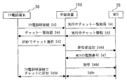
次にTV電話端末1 30からテレビ会議へ参加する動作について、シーケンスを示す図3、画像処理部13の詳細と開催中会議情報取得部14の詳細を示す図1、中継装置10の動作を示すフロー図の図4,5及び画面表示具体例を示す図6に基づいて説明する。
中継装置10は、記載していないが内部にプロセッサとメモリがあり、メモリ上に記憶されたプログラムにより上記各構成要素の機能を実行している。図4のステップ(以後ステップの記述を省略する)S61で、MCU接続部15から内部のMCU一覧情報部141に記憶されている全てのMCUに接続する。そして回線接続部11ではS62で、絶えずTV電話端末からの接続があるかをチェックしている。
ユーザは、TV電話端末30を使い、中継装置10に対して電話をかける。中継装置10はTV電話端末30からの接続を受けると、先ず図4のS63、つまり図3のシーケンスS43で、そのTV電話端末30の発呼番号を取得する。また、開催中会議情報取得部14がS41aでMCU20に問合せ、またS41bでMCU21に問合せて、S42aでMCU20から現在テレビ会議を開催中のチャット情報を取得し、またS42bでMCU21からチャット情報を取得して、S64で開催中のチャット一覧を知る。そしてS65で情報を渡された画像処理部13は、S66で情報を例えばテキスト形式にして、端末から見ることができる中継装置内の表示画面に図6に例を示す形式で開催中チャット一覧を表示する。この例では、4つのMCUから開催中(実行中)である、映画、野球、カラオケ、それに天気に関するテレビ会議をそれぞれ集めて一覧表示している。この情報がS67、つまり図3のS44でTV電話端末側に送信さる。TV電話端末30においてこの画面を見て、現在開催中のテレビ会議を知ることができる。
Next, with respect to the operation of participating in the video conference from the videophone terminal 130, FIG. 3 showing the sequence, FIG. 1 showing the details of the image processing unit 13 and the details of the ongoing conference information acquisition unit 14, and the operation of the
Although not described, the
The user uses the
なお、中継装置10は、予め定期的にS41a,S41b等のS41で実行中チャット一覧取得シーケンスを実行して、S42で実行中チャット情報を得て実行中のテレビ会議を一覧画面表示しておくことでもよい。この場合は、S43のTV電話端末からの問合せシーケンスに対して、直ちにS44のチャット一覧画面を送ることができる。
ユーザはTV電話端末30上で図5のS68で、DFMT信号などを使って、表示された一覧の中から参加したいチャット(テレビ会議)を選択する。選択の方法は、例えば、2,4,6,8の数字キーでカーソル移動し、5の数字キーで選択する方法などが考えられる。図6の例では、上下にカーソルを動かして4つのテレビ会議の中から5人が参加しているカラオケを、例えば5の数字キー押下による「決定」で選択している。図5のS69、つまりS45で転送処理部16のTV電話端末電話番号取得部161がTV電話端末30からの選択信号を受信すると、中継装置10はS70、S46で、MCU20に対してチャットに参加する端末番号としてTV電話端末30の発呼番号を伝える。その応答としてMCU20はS47で、目的のチャットに接続するための電話番号を中継装置10へ渡す。中継装置10はS71でこれを取得し、S72つまりS48で、TV電話端末30との間のAV呼をMCUから渡された番号へ転送する。MCU20はS49で、転送されてきた電話を着信し、発番号から目的のチャットへ参加させる。
The
The user selects a chat (video conference) to be joined from the displayed list using the DFMT signal or the like in S68 of FIG. 5 on the
以上のように、中継装置10により開催中のテレビ会議を一覧表示し、かつTV電話端末から選択してきたチャットのMCUへ電話番号を転送する機能を待たせたので、任意のTV電話端末を使って任意のチャットへ参加することが可能となる。
As described above, since the function for displaying a list of the video conferences being held by the
実施の形態2.
上記の実施の形態では、TV電話端末から仲介装置に表示された現在開催中のテレビ会議をみて、任意のチャットを選択して参加する装置とシステムを説明した。次に本実施の形態では、オペレータサーバ50を接続してテレビ会議を開催する装置、システムを説明する。
図7は、本実施の形態におけるシステム構成を示す図である。図において、図2の接続形態に加えて、オペレータサーバ50がMCUまたは通信網40に接続される。
Embodiment 2. FIG.
In the above-described embodiment, an apparatus and a system for selecting and participating in an arbitrary chat by watching a currently held video conference displayed on a mediation apparatus from a TV phone terminal has been described. Next, in this embodiment, an apparatus and a system for holding a video conference by connecting the
FIG. 7 is a diagram showing a system configuration in the present embodiment. In the figure, an
次に装置間のシーケンスを示す図8に基づいて各装置が行う動作を説明する。
先ずMCU20によるテレビ会議を行う。勿論、複数のチャットを実行していてもよい。そして各チャットには、サービス提供者のオペレータサーバ50がS40aとS40bで、1チャットにつき1台ずつ接続され、オペレータサーバ50経由でオペレータがチャットに参加する。
Next, operations performed by each device will be described with reference to FIG. 8 showing a sequence between the devices.
First, a video conference by the
ユーザ1はTV電話端末1 30から中継装置10cに対してS45bで電話をかける。中継装置10cは、TV電話端末30との間に電話の呼を確立し、同時にチャットに参加するユーザ2の電話番号の入力を求める画面を表示する。S45cでTV電話端末30からは、DTMFなどを使い、テレビ会議相手のTV電話端末2 31の電話番号を入力する。中継装置10cは、MCU20上で実行中のチャットの中から、例えばオペレータしか接続していないチャットを選択して、S46でTV電話端末30との間の、電話の呼をMCU20へ転送する。また、入力されたTV電話端末2 31の電話番号をMCU20へ伝えて、S48でこれらの情報を転送して、TV電話端末31をチャットに参加させて、MCU20からTV電話端末31へダイアルアウトするように指示を出す。これによりS49とS51で、TV電話端末30、TV電話端末31、オペレータサーバ50によるテレビ会議が成立して、TV電話端末による3者のチャットが行える。
なお、上記ではMCU20からS49で呼接続をして3者テレビ会議を行う例を説明したが、中継装置10cがTV電話端末30の要求に基づいてTV電話端末2 31の呼を接続して後、これをMCU20に転送してテレビ会議に参加する動作としてもよい。
The
In the above description, an example is described in which the
以上により、ユーザ1およびユーザ2は、オペレータを含む3者のテレビ会議を開催することが出来る。このときオペレータについては、中継装置10cが空きとなっているものを任意に選択している。
こうして、例えば通訳サービスなどを行う際に、ユーザ1は中継装置10cへTV電話端末30を通じて電話し、オペレータとしての通訳を交えて、会話したい相手であるユーザ2のTV電話端末31の電話番号を入力することにより、通訳者であるオペレータを含めたテレビ会議を開催することができ、通訳サービスを享受できる。
あるいは許可を得て専門家をオペレータとして依頼し、その専門家を巻き込んだテレビ会議を行うことができる。
As described above, the
Thus, for example, when performing an interpreting service or the like, the
Alternatively, an expert can be requested as an operator with permission, and a video conference involving the expert can be performed.
実施の形態3.
上記の実施の形態では、中継装置がTV電話端末との間の電話呼をMCUへ転送する、つまり仲介する例を説明したが、本実施の形態では、呼を転送することに代えて、中継装置からMCUに対して別途の番号呼を通知し、MCUはこの通知された呼に接続する。つまり中継装置はTV電話端末とMCUとの双方を繋げて文字通り中継接続する形態を説明する。
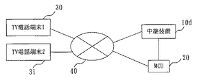
図9は、本実施の形態におけるシステム構成を示す図である。即ち中継装置10dとMCU20間で画像通信回線が接続されて、各TV電話端末30等は直接には中継装置10dとのみ電話の呼を交換する。即ち図1の構成において、転送処理部は回線接続部で受けたTV電話端末からの通信情報を選択されたMCUと接続するMCU接続部に送信し、またMCU接続部が受けた通信情報を回線接続部に送信する。
Embodiment 3 FIG.
In the above embodiment, an example has been described in which the relay device transfers a telephone call with a TV phone terminal to the MCU, that is, mediates, but in this embodiment, instead of transferring a call, a relay is performed. The device notifies the MCU of a separate number call, and the MCU connects to the notified call. That is, the relay device literally relays and connects both the TV phone terminal and the MCU.
FIG. 9 is a diagram showing a system configuration in the present embodiment. That is, an image communication line is connected between the
次にシーケンスを示す図10を用いて動作について説明する。
中継装置10dは、TV電話端末30からの呼をS43で受けると、S41でMCU20から現在開催中のチャット情報を要求して、S42でこれを取得して装置の画面上に開催中チャット一覧として表示する。ユーザはS45において、表示された一覧の中からTV電話端末30のDTMF信号などを使って参加したいチャットを選択する。ここまでは上記実施の形態での動作と同じである。
中継装置10dは、チャットに参加する端末の電話番号として、独自に用意した中継装置10dの発番号をS46dでMCU20に伝える。MCU20は目的のチャットに参加するための電話番号を中継装置10dへS47で伝える。中継装置10dはS48dで、その番号へTV電話を発呼する。そしてS49eでMCU20と接続している画像情報をS49dでTV電話端末30に転送する。また逆方向のTV電話端末からの画像情報についても、上記と逆のS49d、S49eの順でMCU20に転送する。
Next, the operation will be described with reference to FIG.
When the
The
なお上記の説明では、中継装置10dとMCU20との間は専用の通信回線を設ける場合を説明したが、当然のことながらMCU20は通信網40を経由して中継装置10dと接続し、しかしながらTV電話端末30等は通信網40を経由するが中継装置10dとのみ接続する構成としてもよい。
以上の構成と動作により、TV電話端末30等の電話番号をMCUに伝えないので、TV電話端末30のユーザがその電話番号をMCUへ伝えたくない場合でも、中継装置を介して任意のチャットへ参加することができる。
In the above description, a case where a dedicated communication line is provided between the
With the above configuration and operation, the telephone number of the
実施の形態4.
本実施の形態では、先の実施の形態に加えて、外部にテレビ会議の通信内容である画像、音声を加工する外部装置を接続し、TV電話端末からの内容が変更されてMCUに転送される構成を説明する。
図11は本実施の形態におけるシステム構成を示す図である。図において、図9の接続形態に加えて、中継装置とMCU間に外部装置60を設けている。外部装置60は、中継装置10dより受けたTV電話端末30等からの画像情報や音声信号を加工してMCU20に送信する機能を持っている。
Embodiment 4 FIG.
In this embodiment, in addition to the previous embodiment, an external device that processes the image and sound that is the content of the video conference communication is connected to the outside, and the content from the TV phone terminal is changed and transferred to the MCU. The configuration will be described.
FIG. 11 is a diagram showing a system configuration in the present embodiment. In the figure, in addition to the connection form of FIG. 9, an
次に動作についてシーケンスを示す図12を用いて説明する。
中継装置10dは、TV電話端末30からの接続要求をS43で受けると、S41で問合せて、MCU20から現在開催中のチャット情報をS42で取得し、画面上に開催中チャット一覧として表示する。
ユーザはTV電話端末30上でDTMF信号などを使って、S44で表示された一覧の中から参加したいチャットをS45で選択する。ここまでは上記の実施の形態におけるシーケンスと同様である。
本実施の形態においては、ここで中継装置10dはS46eで、MCU20に対してチャットに参加する端末の電話番号として、外部装置60の発呼番号を伝える。MCU20から中継装置10dに目的のチャットに参加するための電話番号がS47で伝えられる。中継装置10dはその番号を外部装置60へS46fとして伝える。更に中継装置10dは外部装置60へS48dで発呼してTV話接続し、この呼に応じて外部装置60はTV電話接続を受けるとMCU20へTV電話接続を行う。
Next, the operation will be described with reference to FIG.
When receiving the connection request from the
The user uses the DTMF signal or the like on the
In the present embodiment, the
外部装置60では、中継装置10dが中継したTV電話端末30等の画像や音声に対して加工を施す。例えば、色合いを変える、自画像の周りの部分にフレーム画像を表示する、音声のピッチを変更する、等の加工を行う。
こうして、実施の形態3に加えて、ユーザはTV電話端末の画像や音声を外部装置により加工した自画像・音声によって、テレビ会議に参加することが出来る。
なお上記では、外部装置60は中継装置10dから独立した装置としたが、この情報加工機能を中継装置内の開催中会議情報取得部と転送処理部とは別の、独立した部分に設けて、つまり中継装置が外部装置の機能を併せ持つ構成としてもよい。
The
In this manner, in addition to the third embodiment, the user can participate in the video conference by the self-portrait / sound obtained by processing the image and sound of the TV phone terminal by the external device.
In the above description, the
本実施の形態における他の接続形態と動作について説明する。
図13はそのシステム構成を示す図であり、図11の接続において中継装置10e内でテレビ会議の情報ストリームをMCUと外部装置とに分配する構成である。
次に動作についてシーケンスを示す図14を用いて説明する。
中継装置10eは、S43でTV電話端末30からの接続要求を受けてその発番号を取得する。またMCU20等から現在開催中のチャット情報をS42で取得し、画面上に開催中チャット一覧として表示する。TV電話端末30上でS44によりこの情報を見て、S45でDTMF信号などを使って表示された一覧の中から参加したいチャットをS45で選択する。ここまでは上記実施の形態の動作と同様である。
Other connection modes and operations in this embodiment will be described.
FIG. 13 is a diagram showing the system configuration. In the connection of FIG. 11, the video conference information stream is distributed to the MCU and the external device in the
Next, the operation will be described with reference to FIG.
The
中継装置10eはMCU20に対しチャットに参加する端末番号としてTV電話端末30と外部装置60の発呼番号をS46eで伝える。その応答としてMCU20は目的のチャットに接続するための電話番号を中継装置10eS47で渡す。中継装置10eは外部装置60に対して目的のチャットに接続するための電話番号をS46fで渡す。中継装置10eは外部装置60とMCU20とに対して新たにTV電話による発呼をS48dとS48fで行う。外部装置60はTV電話をS48dで着呼すると、中継装置10eから送付されたMCU20の電話番号に対してS48eで発呼する。
また同時に、外部装置60は中継装置10eを経由してTV電話端末30から送られる映像または音声に加工し、MCU20側へ送出する。加工とは、例えば、音声を認識し文字を表示する、画像の動きに合わせたキャラクターを表示する、数秒間遅延させた音声と画像を表示する、等がある。
The
At the same time, the
自画像の画面と自分が話している内容を文字にした画面の両方を含めたTV会議を行う場合、中継装置にてTV電話端末側からのストリームを2つに分割し、片方の画像をMCU20へそのまま送り、片方の音声は外部装置60へ送る。
外部装置60では、ストリーム中の音声を認識し、文字情報に変換し、外部装置60からMCU20へ流すストリームにより、MCU20ではその文字情報を、例えば、図15の部分61に示すように、テロップとして表示させる。このとき、元のストリームとは重ね合わせず、文字情報だけを大きく表示し、読みやすいようにする。MCUでは、中継装置から送られたストリームと、外部装置から送られた文字のストリームを、図15のように、分割表示などすることで、TV電話端末から送られた映像と、その音声を文字ににした表示の両方を表示することができる。
以上により、図11、12の接続と動作に加え、例えば自画像の画面と自分が話している内容を文字にした画面の両方を含めたTV会議を行うなど、通常のTV会議では実施できない付加価値をつけることが出来る。
When performing a TV conference including both the self-image screen and a screen in which the content of what is being spoken is written, the stream from the TV phone terminal side is divided into two by the relay device, and one image is sent to the
The
As described above, in addition to the connections and operations shown in FIGS. 11 and 12, for example, a video conference including both a self-portrait screen and a screen in which the content of what is being spoken is performed, a value added that cannot be performed in a normal TV conference. Can be attached.
実施の形態5.
上記の各実施の形態は、構成要素が専用の要素であるとして説明をしたが、汎用の計算機を用い、プロセッサとメモリを用意して、これらの専用要素に相当するプログラムをこのメモリ上に記憶して、同等の機能を得るようにしてもよい。
即ち例えば既存のMCUに上記の汎用の計算機を付加して、または汎用の計算機機能を持つサーバに付加して中継装置相当を構成して、実施の形態1以降における各構成要素の機能を搭載するようにしてもよい。
Embodiment 5 FIG.
Each of the above embodiments has been described on the assumption that the components are dedicated elements. However, a general-purpose computer is used, a processor and a memory are prepared, and a program corresponding to these dedicated elements is stored in the memory. Thus, an equivalent function may be obtained.
That is, for example, the above-mentioned general-purpose computer is added to an existing MCU, or added to a server having a general-purpose computer function to constitute a relay device, and the functions of each component in the first and subsequent embodiments are mounted. You may do it.
10,10c,10d,10e 中継装置、11 回線接続部、12 チャット選択部、13 画像処理部、14 開催中会議情報取得部、15 MCU接続部、16 転送処理部、17 制御部、20 MCU1、21 MCU2、30 TV電話端末(1)、31 TV電話端末n、50 オペレータサーバ、141 MCU一覧情報部、142 MCU登録部、161 TV電話端末電話番号取得部、162 呼接続転送部、S40a チャット開催通知ステップ、S40b チャット参加ステップ、S41 実行中チャット一覧取得ステップ、S42 実行中チャット情報転送ステップ、S43 TV電話呼接続ステップ、S44 チャット一覧画面情報取得ステップ、S45,S45c チャット選択ステップ、S45b 64kAV呼接続ステップ、S46 端末番号・参加者追加通知ステップ、S46d,46e 参加者追加通知ステップ、S46f MCU電話番号通知ステップ,S47 MCU電話番号通知ステップ、S48 電話端末番号転送ステップ、S48d,48e,48f 発呼ステップ、S49,S49d,49e,49f TV電話呼接続ステップ、S50 ダイヤルアウト接続ステップ,S51 チャット参加ステップ、S61 MCUとの通信接続ステップ,S62 TV電話端末からの接続要求チェック・ステップ、S63 開催中のテレビ会議情報送信要求ステップ、S64 開催中テレビ会議情報取得ステップ、S66 画像処理して開催中のテレビ会議一覧を表示するステップ、S67 テレビ会議一覧送信ステップ、S68 チャット選択された内容を伝えるステップ、S69 TV電話番号取得ステップ、S70 チャット参加者通知ステップ、S71 MCU電話番号取得ステップ、S72 呼転送ステップ。 10, 10c, 10d, 10e Relay device, 11 line connection unit, 12 chat selection unit, 13 image processing unit, 14 ongoing conference information acquisition unit, 15 MCU connection unit, 16 transfer processing unit, 17 control unit, 20 MCU1, 21 MCU2, 30 TV phone terminal (1), 31 TV phone terminal n, 50 Operator server, 141 MCU list information section, 142 MCU registration section, 161 TV phone terminal phone number acquisition section, 162 Call connection transfer section, S40a Chat holding Notification step, S40b Chat participation step, S41 Active chat list acquisition step, S42 Active chat information transfer step, S43 TV phone call connection step, S44 Chat list screen information acquisition step, S45, S45c Chat selection step, S45b 64kAV call connection Step S46 terminal number / participant addition notification step, S46d, 46e participant addition notification step, S46f MCU telephone number notification step, S47 MCU telephone number notification step, S48 telephone terminal number transfer step, S48d, 48e, 48f calling step, S49, S49d, 49e, 49f TV phone call connection step, S50 dial-out connection step, S51 chat participation step, S61 communication connection step with MCU, S62 connection request check step from TV phone terminal, S63 video conference being held Information transmission request step, S64 Current video conference information acquisition step, S66 Image processing and displaying a list of ongoing video conferences, S67 Video conference list transmission step, S68 Chat to convey the selected content -Up, S69 TV phone number acquisition step, S70 chat participant notification step, S71 MCU phone number acquisition step, S72 call forwarding step.
Claims (1)
上記回線接続部が画像伝送機能付電話端末との間で呼を接続した場合、複数の多地点制御装置の各多地点制御装置からテレビ会議の実行が開始されて実行途中のテレビ会議の内容と当該実行途中のテレビ会議を実行している多地点制御装置とを表すテレビ会議情報を複数取得する開催中会議情報取得部と、
上記開催中会議情報取得部により取得された複数のテレビ会議情報を上記回線接続部を介して上記画像伝送機能付電話端末へ送信し、上記画像伝送機能付電話端末のユーザが参加するテレビ会議のテレビ会議情報をユーザに選択させる画像処理部と、
上記画像処理部が送信した複数のテレビ会議情報の中から上記ユーザにより選択されたテレビ会議情報を上記画像伝送機能付電話端末から受信し、
受信したテレビ会議情報により表された上記ユーザが参加するテレビ会議を実行している多地点制御装置へ、上記画像伝送機能付電話端末の発呼番号を送信し、上記発呼番号を送信したことに対する応答として上記多地点制御装置から上記ユーザが参加するテレビ会議に接続するための電話番号を受信し、
上記画像伝送機能付電話端末との間の呼を上記受信した電話番号に対して転送し、上記画像伝送機能付電話端末のユーザを上記ユーザが参加するテレビ会議に参加させる転送処理部と
を備えたことを特徴とする任意参加中継装置。 Accepts a connection request from a telephone terminal with an image transmission function, acquires a calling number of the telephone terminal with an image transmission function from the telephone terminal with an image transmission function, and connects a call with the telephone terminal with an image transmission function A line connection;
When the line connection unit connects a call to a telephone terminal with an image transmission function, the video conference is started from each multi-point control device of the plurality of multi-point control devices, and the content of the video conference being executed An ongoing conference information acquisition unit that acquires a plurality of video conference information representing the multipoint control device that is executing the video conference in progress,
A plurality of video conference information acquired by the ongoing conference information acquisition unit is transmitted to the telephone terminal with an image transmission function via the line connection unit, and a video conference of which the user of the telephone terminal with the image transmission function participates An image processing unit that allows the user to select video conference information;
Receiving the video conference information selected by the user from the plurality of video conference information transmitted by the image processing unit from the telephone terminal with the image transmission function;
The calling number of the telephone terminal with the image transmission function is transmitted to the multipoint control device that is executing the video conference in which the user participates represented by the received video conference information, and the calling number is transmitted. As a response to the multipoint control device, a telephone number for connecting to the video conference in which the user participates is received,
A transfer processing unit for transferring a call with the telephone terminal with the image transmission function to the received telephone number and for allowing the user of the telephone terminal with the image transmission function to participate in a video conference in which the user participates. A voluntary participation relay device characterized by that.
Priority Applications (1)
| Application Number | Priority Date | Filing Date | Title |
|---|---|---|---|
| JP2004319998A JP4545552B2 (en) | 2004-11-04 | 2004-11-04 | Voluntary participation relay device |
Applications Claiming Priority (1)
| Application Number | Priority Date | Filing Date | Title |
|---|---|---|---|
| JP2004319998A JP4545552B2 (en) | 2004-11-04 | 2004-11-04 | Voluntary participation relay device |
Publications (2)
| Publication Number | Publication Date |
|---|---|
| JP2006135456A JP2006135456A (en) | 2006-05-25 |
| JP4545552B2 true JP4545552B2 (en) | 2010-09-15 |
Family
ID=36728630
Family Applications (1)
| Application Number | Title | Priority Date | Filing Date |
|---|---|---|---|
| JP2004319998A Expired - Fee Related JP4545552B2 (en) | 2004-11-04 | 2004-11-04 | Voluntary participation relay device |
Country Status (1)
| Country | Link |
|---|---|
| JP (1) | JP4545552B2 (en) |
Families Citing this family (4)
| Publication number | Priority date | Publication date | Assignee | Title |
|---|---|---|---|---|
| JP5217724B2 (en) * | 2008-07-22 | 2013-06-19 | ブラザー工業株式会社 | server |
| JP5224966B2 (en) * | 2008-08-04 | 2013-07-03 | 富士通株式会社 | Voice transcription server |
| JP6064209B2 (en) * | 2013-02-01 | 2017-01-25 | 東日本電信電話株式会社 | Call system and call relay method |
| CN107690056A (en) * | 2016-08-05 | 2018-02-13 | 鸿富锦精密工业(深圳)有限公司 | Video Conference Controlling System and method |
Family Cites Families (2)
| Publication number | Priority date | Publication date | Assignee | Title |
|---|---|---|---|---|
| JP2003235018A (en) * | 2002-02-08 | 2003-08-22 | Megafusion Corp | Video conference system and multi-point education system |
| JP2004187126A (en) * | 2002-12-05 | 2004-07-02 | Megachips System Solutions Inc | Video conference system |
-
2004
- 2004-11-04 JP JP2004319998A patent/JP4545552B2/en not_active Expired - Fee Related
Also Published As
| Publication number | Publication date |
|---|---|
| JP2006135456A (en) | 2006-05-25 |
Similar Documents
| Publication | Publication Date | Title |
|---|---|---|
| US7312809B2 (en) | Method and apparatus for controlling a conference call | |
| KR101417002B1 (en) | A mobile communication terminal having multilateral image communication function and multilateral method for converting image communication mode thereof | |
| TWI321955B (en) | ||
| US8477662B2 (en) | Court video teleconferencing system and method | |
| CN101465919B (en) | Method and system for implementing video conference | |
| CN101478642A (en) | Multi-picture mixing method and apparatus for video meeting system | |
| CN104580995A (en) | Communication method and device of video conference | |
| US7425979B2 (en) | Communication system | |
| JP2003348213A (en) | Dual-purpose videophone for internet and public switched telephone network | |
| KR20140098573A (en) | Apparatus and Methd for Providing Video Conference | |
| JP2008147877A (en) | Conference system | |
| US9438857B2 (en) | Video conferencing system and multi-way video conference switching method | |
| US9013537B2 (en) | Method, device, and network systems for controlling multiple auxiliary streams | |
| JP4545552B2 (en) | Voluntary participation relay device | |
| JP2005311670A (en) | Video conference terminal, video conference system, video conference method and program thereof | |
| WO2011010563A1 (en) | Video call system, master-side terminal, slave-side terminal, and program | |
| US20140267574A1 (en) | Court video teleconferencing system & method | |
| KR100193684B1 (en) | Method and apparatus for video and audio transmission and multi-party remote communication network in video conferencing or multimedia network | |
| KR19990025932A (en) | Multi video conference system | |
| JP2012080186A (en) | Video speech system, master terminal, and slave terminal | |
| JP2003235018A (en) | Video conference system and multi-point education system | |
| KR100463876B1 (en) | A Method For Controlling Video Conference | |
| JP6349764B2 (en) | Transmission system and program | |
| KR20030021222A (en) | A System For Controlling Video Conference Using SIP | |
| KR100592432B1 (en) | Small multi-party conference channel formation method using SPI service |
Legal Events
| Date | Code | Title | Description |
|---|---|---|---|
| A621 | Written request for application examination |
Free format text: JAPANESE INTERMEDIATE CODE: A621 Effective date: 20070615 |
|
| A977 | Report on retrieval |
Free format text: JAPANESE INTERMEDIATE CODE: A971007 Effective date: 20100415 |
|
| A131 | Notification of reasons for refusal |
Free format text: JAPANESE INTERMEDIATE CODE: A131 Effective date: 20100420 |
|
| A521 | Request for written amendment filed |
Free format text: JAPANESE INTERMEDIATE CODE: A523 Effective date: 20100611 |
|
| TRDD | Decision of grant or rejection written | ||
| A01 | Written decision to grant a patent or to grant a registration (utility model) |
Free format text: JAPANESE INTERMEDIATE CODE: A01 Effective date: 20100629 |
|
| A01 | Written decision to grant a patent or to grant a registration (utility model) |
Free format text: JAPANESE INTERMEDIATE CODE: A01 |
|
| A61 | First payment of annual fees (during grant procedure) |
Free format text: JAPANESE INTERMEDIATE CODE: A61 Effective date: 20100630 |
|
| FPAY | Renewal fee payment (event date is renewal date of database) |
Free format text: PAYMENT UNTIL: 20130709 Year of fee payment: 3 |
|
| R150 | Certificate of patent or registration of utility model |
Free format text: JAPANESE INTERMEDIATE CODE: R150 |
|
| LAPS | Cancellation because of no payment of annual fees |