JP4541941B2 - Parts such as titanium alloy tappets and manufacturing method thereof - Google Patents
Parts such as titanium alloy tappets and manufacturing method thereof Download PDFInfo
- Publication number
- JP4541941B2 JP4541941B2 JP2005075567A JP2005075567A JP4541941B2 JP 4541941 B2 JP4541941 B2 JP 4541941B2 JP 2005075567 A JP2005075567 A JP 2005075567A JP 2005075567 A JP2005075567 A JP 2005075567A JP 4541941 B2 JP4541941 B2 JP 4541941B2
- Authority
- JP
- Japan
- Prior art keywords
- tappet
- titanium alloy
- treatment
- manufacturing
- diamond
- Prior art date
- Legal status (The legal status is an assumption and is not a legal conclusion. Google has not performed a legal analysis and makes no representation as to the accuracy of the status listed.)
- Expired - Fee Related
Links
Images


Classifications
-
- F—MECHANICAL ENGINEERING; LIGHTING; HEATING; WEAPONS; BLASTING
- F01—MACHINES OR ENGINES IN GENERAL; ENGINE PLANTS IN GENERAL; STEAM ENGINES
- F01L—CYCLICALLY OPERATING VALVES FOR MACHINES OR ENGINES
- F01L1/00—Valve-gear or valve arrangements, e.g. lift-valve gear
- F01L1/12—Transmitting gear between valve drive and valve
- F01L1/14—Tappets; Push rods
- F01L1/143—Tappets; Push rods for use with overhead camshafts
-
- F—MECHANICAL ENGINEERING; LIGHTING; HEATING; WEAPONS; BLASTING
- F01—MACHINES OR ENGINES IN GENERAL; ENGINE PLANTS IN GENERAL; STEAM ENGINES
- F01L—CYCLICALLY OPERATING VALVES FOR MACHINES OR ENGINES
- F01L2301/00—Using particular materials
-
- F—MECHANICAL ENGINEERING; LIGHTING; HEATING; WEAPONS; BLASTING
- F01—MACHINES OR ENGINES IN GENERAL; ENGINE PLANTS IN GENERAL; STEAM ENGINES
- F01L—CYCLICALLY OPERATING VALVES FOR MACHINES OR ENGINES
- F01L2303/00—Manufacturing of components used in valve arrangements
-
- Y—GENERAL TAGGING OF NEW TECHNOLOGICAL DEVELOPMENTS; GENERAL TAGGING OF CROSS-SECTIONAL TECHNOLOGIES SPANNING OVER SEVERAL SECTIONS OF THE IPC; TECHNICAL SUBJECTS COVERED BY FORMER USPC CROSS-REFERENCE ART COLLECTIONS [XRACs] AND DIGESTS
- Y10—TECHNICAL SUBJECTS COVERED BY FORMER USPC
- Y10T—TECHNICAL SUBJECTS COVERED BY FORMER US CLASSIFICATION
- Y10T29/00—Metal working
- Y10T29/49—Method of mechanical manufacture
- Y10T29/49229—Prime mover or fluid pump making
- Y10T29/49247—Valve lifter making
Landscapes
- Engineering & Computer Science (AREA)
- Mechanical Engineering (AREA)
- General Engineering & Computer Science (AREA)
- Valve-Gear Or Valve Arrangements (AREA)
Description
本発明は、自動車 (自動二輪車を含む) 等のバルブ開閉機構に使用されるチタン合金製タペット等の機械装置の部品として使用されるチタン合金製の部材と、その製造方法に関する。 The present invention includes a member made of titanium alloy used as a component of a motor vehicle (including motorcycles) machinery titanium alloy tappet or the like to be used for valve opening and closing mechanism such as relates to its production how.
四輪自動車および二輪自動車等は、排気ガスや騒音の低減等を図ると共に、高出力化と低燃費化が図られている。 In automobiles and motorcycles, exhaust gas and noise are reduced, and higher output and fuel efficiency are achieved.
そして、前記高出力化と低燃費化のためには、部品の軽量化を避けて通ることができない。具体的には、エンジン等の部品、例えば、バルブの開閉機構に使用されているタペット等の部品の、軽量化が進められている。本出願人も、既にこの種の発明(以下、先願発明という)をおこない、その発明については既に出願している (特許文献1参照)。 In order to achieve high output and low fuel consumption, it is impossible to avoid weight reduction of parts. Specifically, weight reduction of parts, such as an engine, for example, parts, such as a tappet currently used for the opening-and-closing mechanism of a valve, is progressing. The present applicant has already made this kind of invention (hereinafter referred to as a prior invention) and has already filed the invention (see Patent Document 1).
しかしながら、従来の鋼を素材とした場合には、強度の点からこれ以上の薄肉化をおこなうことは困難となっている。 However, when conventional steel is used as a raw material, it is difficult to further reduce the thickness from the viewpoint of strength.
そこで、軽量で強度の高い材料として、チタン合金が考えられるが、チタン合金の場合には、摺動性能が低く、つまり摩擦係数が高く且つ凝着しやすく、前述したような高速(例えば、エンジン回転数にして、15,000rpm〜18,000rpm)で摺動するような箇所に使用すると焼付きをおこす恐れがあるため、単に鋼をチタン合金に置き換えることはでき難い。 Therefore, a titanium alloy can be considered as a lightweight and high-strength material. However, in the case of a titanium alloy, the sliding performance is low, that is, the friction coefficient is high and the adhesive is easy to adhere. If it is used at a location that slides at a rotational speed of 15,000 rpm to 18,000 rpm, it may cause seizure, so that it is difficult to simply replace steel with a titanium alloy.
また、前述した本出願人の発明にかかる、鋼表面にDLC(ダイヤモンドライク・カーボン:本明細書において「DLC」という)膜を形成するという、摩擦抵抗を小さくするという手法を、このチタン合金に応用することを試みたが、チタン合金とDLC膜加工との相性が悪く、つまり、鋼等の場合に比べて、チタン合金の表面へのDLC膜の密着強度が小さく、短時間の運転で、DLC膜がチタン合金表面から剥離し易い。この結果、チタン合金の摺動部分にDLC膜を施すことには改良が望まれる。
本発明は、このような状況に鑑みて行われたもので、軽量で強度の高いチタン合金に着目するとともに、このチタン合金の有する欠点を補完することによって、高速で摺動可能なチタン合金製タペット等の機械装置の部品として使用されるチタン合金製の部材を提供するとともに、その製造方法を提供することを目的とする。 The present invention has been made in view of such circumstances, and is made of a titanium alloy that can slide at high speed by paying attention to a lightweight and high-strength titanium alloy and complementing the drawbacks of the titanium alloy. while providing member made of titanium alloy used as a component of the machinery of the tappet or the like, and to provide a manufacturing how.
本発明の前記課題は、以下の構成からなるチタン合金製タペット等の機械装置の部品として使用されるチタン合金製の部材と、その製造方法によって解決することができる。 The object of the present invention, a titanium alloy member used as a component of a mechanical device such as a titanium alloy tappet comprising the following structure can be resolved by the method of manufacturing the same.
本第1の発明にかかるチタン合金製タペットは、バルブ開閉機構に使用するチタン合金製タペットであって、
このタペットの少なくとも摺動する部分の表面に、表面硬化処理を施してあることを特徴とする。
The titanium alloy tappet according to the first aspect of the present invention is a titanium alloy tappet used for a valve opening / closing mechanism,
A surface of at least a sliding portion of the tappet, characterized in that are subjected to surface hardening treatment.
前述のように構成された本第1の発明にかかるチタン合金製タペットによれば、表面に表面硬化処理を施すことによって、表面硬度が増加するため、耐凝着性が向上するとともに、耐久性が向上する。
例えば、前記表面硬化処理が、浸炭処理である場合には、表面に炭化層が形成される結果、表面硬度が増加して、耐凝着性が向上するとともに、耐久性が飛躍的に向上する。この浸炭処理の場合には、表面に白層が形成されないため、DLC膜の形成が容易に行えるという利点を有する。
また、前記表面硬化処理が、窒化処理である場合には、表面に窒化層が形成される結果、表面硬度が増加して、耐凝着性が向上するとともに、耐久性が向上する。この窒化処理である場合には、浸炭処理に比べて処理温度が低いという利点を有する。
According to the titanium alloy tappet according to the first invention configured as described above, the surface hardness is increased by subjecting the surface to surface hardening treatment, so that adhesion resistance is improved and durability is improved. Will improve.
For example, when the surface hardening treatment is a carburizing treatment, a carbonized layer is formed on the surface. As a result, the surface hardness is increased, adhesion resistance is improved, and durability is dramatically improved. . In the case of this carburizing treatment, since a white layer is not formed on the surface, there is an advantage that a DLC film can be easily formed.
When the surface hardening treatment is a nitriding treatment, a nitride layer is formed on the surface. As a result, the surface hardness is increased, the adhesion resistance is improved, and the durability is improved. In the case of this nitriding treatment, there is an advantage that the treatment temperature is lower than that of the carburizing treatment.
また、本第2の発明にかかるチタン合金製タペットは、バルブ開閉機構に使用するチタン合金製タペットであって、
このタペットの少なくとも摺動する部分の表面に、表面硬化処理が施され、しかる後に、ダイヤモンドライク・カーボン膜(DLC膜ともいう)が形成されていることを特徴とする。
The titanium alloy tappet according to the second aspect of the present invention is a titanium alloy tappet used for a valve opening / closing mechanism,
A surface of at least a sliding portion of the tappet, surface hardening treatment into force, and thereafter, (also referred to as DLC film) diamond-like carbon film, characterized in that is formed.
また、本第3の発明にかかるチタン合金製タペットは、バルブ開閉機構に使用するチタン合金製タペットであって、The titanium alloy tappet according to the third aspect of the present invention is a titanium alloy tappet used for a valve opening / closing mechanism,
このタペットの少なくとも摺動する部分の表面に、炭化層又は窒化層が形成され、その層の上にダイヤモンドライク・カーボン膜が形成されていることを特徴とする。 A carbonized layer or a nitrided layer is formed on the surface of at least the sliding portion of the tappet, and a diamond-like carbon film is formed on the layer.
前述のように構成された本第2又は第3の発明にかかるチタン合金製タペットによれば、摺動する部分の表面に表面硬化処理、例えば、浸炭処理又は窒化処理を施すことによって、表面に炭化層又は窒化層が形成されて表面硬度が増加し、次にその炭化層又は窒化層の表面にDLC膜を形成することによって、摩擦抵抗が低減されるとともに耐磨耗性も向上し、しかも、DLC膜がチタン合金表面から短時間で剥離し難い。 According to the titanium alloy tappet according to the second or third invention configured as described above, the surface of the sliding portion is subjected to surface hardening treatment, for example, carburizing treatment or nitriding treatment , so that the surface is treated. carbide layer or nitride layer is formed by the surface hardness is increased, then the surface of the carbide layer or nitride layer by the forming the D LC film, also the abrasion resistance together with friction resistance is reduced In addition, the DLC film is hardly peeled off from the titanium alloy surface in a short time.
そして、前記チタン合金製タペットにおいて、前記浸炭処理が施された後で且つ前記ダイヤモンドライク・カーボン膜が形成される前に、前記摺動する部分の表面に酸化被膜除去処理が施されていると、チタン合金とDLC膜との密着性が飛躍的に向上する。And, in the titanium alloy tappet, after the carburizing process and before the diamond-like carbon film is formed, an oxide film removing process is performed on the surface of the sliding portion. In addition, the adhesion between the titanium alloy and the DLC film is dramatically improved.
そして、前記チタン合金製タペットにおいて、前記タペットに使用されるチタン合金が、Ti-6AL-4V であると、好ましい構成となる。 And in the said titanium alloy tappet, when the titanium alloy used for the said tappet is Ti-6AL-4V, it becomes a preferable structure.
また、本第4の発明にかかるチタン合金製の部材は、機械装置の部品として使用するチタン合金製の部材であって、Further, the titanium alloy member according to the fourth invention is a titanium alloy member used as a component of a mechanical device,
このチタン合金製の部材の少なくとも摺動する部分の表面に、浸炭処理が施され、しかる後に、ダイヤモンドライク・カーボン膜が形成されていることを特徴とする。 The titanium alloy member is characterized in that at least the surface of the sliding portion is subjected to carburizing treatment, and then a diamond-like carbon film is formed.
前述のように構成された本第4の発明にかかるチタン合金製の部材によれば、摺動する部分の表面に、炭化層又は窒化層が形成されて表面硬度が増加し、次にその炭化層又は窒化層の表面にDLC膜を形成することによって、摩擦抵抗が低減されるとともに耐磨耗性も向上し、しかも、DLC膜がチタン合金表面から短時間で剥離し難い。According to the titanium alloy member according to the fourth aspect of the present invention configured as described above, a carbonized layer or a nitrided layer is formed on the surface of the sliding portion to increase the surface hardness. By forming the DLC film on the surface of the layer or nitride layer, the frictional resistance is reduced and the wear resistance is improved, and the DLC film is hardly peeled off from the titanium alloy surface in a short time.
また、本第5の発明にかかるチタン合金製タペットの製造方法は、バルブ開閉機構に使用するチタン合金製タペットの製造方法であって、
このタペットの少なくとも摺動する部分の表面に、表面硬化処理を施したことを特徴とする。
The titanium alloy tappet manufacturing method according to the fifth invention is a titanium alloy tappet manufacturing method used for a valve opening / closing mechanism,
A surface hardening treatment is performed on the surface of at least the sliding portion of the tappet.
前述のように構成された本第5の発明にかかるチタン合金製タペットの製造方法によれば、前記第1の発明にかかるチタン合金製タペットを製造することができる。According to the titanium alloy tappet manufacturing method according to the fifth invention configured as described above, the titanium alloy tappet according to the first invention can be manufactured.
そして、前記第5の発明にかかるチタン合金製タペットの製造方法において、前記表面硬化処理の後に、
前記少なくとも摺動する部分にダイヤモンドライク・カーボン膜を形成すると、前記本第2の発明にかかるチタン合金製タペットを提供することができる。 And in the manufacturing method of the titanium alloy tappet according to the fifth invention, after the surface hardening treatment ,
When a diamond-like carbon film is formed on at least the sliding portion, the titanium alloy tappet according to the second invention can be provided.
そして、前記第5の発明にかかるチタン合金製タペットの製造方法において、前記ダイヤモンドライク・カーボン膜を形成する前に、少なくとも該ダイヤモンドライク・カーボン膜を形成する箇所に酸化被膜除去処理を施すと、つまり、前記浸炭処理又は窒化処理の後に、当該タペットの少なくとも摺動する部分に、酸化被膜除去を施し、しかる後に、DLC膜を形成すると、チタン合金とDLC膜との密着性が飛躍的に向上する。 And, in the method for producing a titanium alloy tappet according to the fifth invention, before forming the diamond-like carbon film, at least a portion where the diamond-like carbon film is formed is subjected to an oxide film removal treatment, That is, after carburizing or nitriding , removing the oxide film on at least the sliding part of the tappet and then forming the DLC film dramatically improves the adhesion between the titanium alloy and the DLC film. To do.
また、前記第5の発明にかかるチタン合金製タペットの製造方法において、前記酸化被膜除去処理が、研磨、エッチング、ショットブラスト、ショットピーニング、又はスパッタリングのいずれかの処理であると、既存の工具あるいは装置を用いて酸化被膜の除去がおこなえる点で、好ましい構成となる。 Further, in the method for manufacturing a titanium alloy tappet according to the fifth aspect of the present invention, if the oxide film removal process is any one of polishing, etching, shot blasting, shot peening, or sputtering, an existing tool or This is a preferable configuration in that the oxide film can be removed using an apparatus.
また、前記第5の発明にかかるチタン合金製タペットの製造方法において、前記ダイヤモンドライク・カーボン膜の形成を、物理的蒸着法又は化学的蒸着法によっておこなうことができる。 In the titanium alloy tappet manufacturing method according to the fifth invention, the diamond-like carbon film can be formed by a physical vapor deposition method or a chemical vapor deposition method.
また、前記第5の発明にかかるチタン合金製タペットの製造方法において、前記タペットを有底筒状の形態に形成するとともに、
該タペットの内壁面に、その角部と上端内面中央部を除いて当接する治具を配置した状態で、前記表面硬化の一種である浸炭処理又は窒化処理を施すようにすると、浸炭処理又は窒化処理によって、摺動部分となる、タペットの外表面および内壁面の上端内面に炭化層又は窒化層を形成することができるとともに、該浸炭処理又は窒化処理の際の熱(前記形態の治具によるタペットの所望部分の熱だれ)を利用して、タペットの上端面を、バルブ開閉機構のカム面と点接触(あるいは点接触に可及的に近い状態で接触)させるための、中央側で上方に凸状になったクラウニング形状に形成することができる。つまり、従来のタペットでは、熱処理等が終了した状態で、該タペットの上端面を、研磨装置等で、中央側で上方に凸状になったラウンド面状に加工形成していたものが、浸炭処理の熱(所謂「熱だれ」と治具による下方からの支え)を利用して、前記ラウンド面に形成することが可能となる。
Moreover, in the manufacturing method of the titanium alloy tappet according to the fifth invention, the tappet is formed in a bottomed cylindrical shape,
The inner wall surface of the tappet, in the state in which the jig contact except for its corners and upper inner surface central portion, when so applying one type of carburizing or nitriding of the surface hardening, carburizing or nitriding By the treatment , a carbonized layer or a nitrided layer can be formed on the outer surface of the tappet and the upper end inner surface of the inner wall surface, which becomes a sliding portion, and heat during the carburizing treatment or nitriding treatment ( depending on the jig of the above form) The upper end of the tappet is point-contacted with the cam surface of the valve opening / closing mechanism (or contacted as close as possible to the point contact) using the heat of the desired part of the tappet. It can be formed in a crowning shape that is convex. That is, in the conventional tappet, after the heat treatment or the like has been completed, the upper end surface of the tappet is processed and formed into a round surface that is convex upward on the center side by a polishing device or the like. It is possible to form the round surface using heat of processing (so-called “heat dripping” and support from below by a jig).
また、前記第5の発明にかかるチタン合金製タペットの製造方法において、前記浸炭処理として、プラズマ浸炭処理を、チタン合金の表面層の温度が500℃〜850℃の温度下で実施すると、表面層の温度が500℃以上であることから炭素「C」と窒素「N」が該表面層に好ましい状態で拡散するとともに、同じく表面層の温度が850℃以下であることから、熱処理による歪みが実質上問題の無い範囲に収めることができる。 Moreover, in the manufacturing method of the titanium alloy tappet according to the fifth aspect of the invention, when the plasma carburizing treatment is performed at a temperature of the surface layer of the titanium alloy of 500 ° C. to 850 ° C. as the carburizing treatment, Since carbon “C” and nitrogen “N” diffuse into the surface layer in a preferable state since the temperature of the surface layer is 500 ° C. or higher, the temperature of the surface layer is also 850 ° C. or lower. It can be within the range without any problems.
そして、前記第5の発明にかかるチタン合金製タペットの製造方法において、前記タペットに使用されるチタン合金が、Ti-6AL-4V であると、好ましい構成となる。 In the titanium alloy tappet manufacturing method according to the fifth aspect of the present invention, the titanium alloy used for the tappet is preferably Ti-6AL-4V.
前記チタン合金製タペットの製造方法において使用される治具としては、前記タペットが、有底筒状の形態を有するときに、前記治具が、前記タペットの内壁面に角部と上端内面中央部を除いて当接するような形態を有するものが使用される。 The jig used in the method for manufacturing the titanium alloy tappet, said tappet, when having a bottomed cylindrical form, the jig, the corners and the upper inner surface center inner wall surface of the tappet What has a form which contact | abuts except a part is used .
前述のように構成された本治具によれば、浸炭処理の熱によってタペットが熱変形をおこす際に、タペットの上端面を、バルブ開閉機構のカム面と点接触(あるいは点接触に可及的に近い状態で接触)させるための、中央側で上方に凸状になったクラウニング形状の面に形成することができる。また、タペットの上端部の内壁面のバルブ端面(あるいはシム端面)と当接する部分をも十分に硬化させることができる。従って、このような治具によって、タペットは大きな負荷を受けて高速で摺動しても、十分に耐え得ることは勿論のこと、低い摩擦力で作動することができる。 According to the jig configured as described above, when the tappet is thermally deformed by the heat of the carburizing process, the upper end surface of the tappet is point-contacted with the cam surface of the valve opening / closing mechanism (or possible for point contact). In a close-up state), it can be formed on a crowned surface convex upward on the center side. In addition, the portion of the inner wall surface of the upper end portion of the tappet that contacts the valve end surface (or shim end surface) can be sufficiently cured. Therefore, with such a jig, the tappet can be operated with a low frictional force as well as being able to withstand a large load even when it is slid at a high speed.
前述のように構成された本第1〜第4の発明にかかるチタン合金製の部材あるいはタペットによれば、軽量で強度の高いチタン合金の有する欠点を表面処理することによって補完し、高速で摺動可能なチタン合金製の部材あるいはタペットを提供することができる。 According to the titanium alloy member or tappet according to the first to fourth inventions configured as described above, the disadvantages of the lightweight and high-strength titanium alloy are compensated for by surface treatment, and sliding is performed at high speed. A movable titanium alloy member or tappet can be provided.
また、前述のように構成された本第5の発明にかかるチタン合金製の部材あるいはタペットの製造方法によれば、前記第1〜第4の発明にかかるチタン合金製の部材あるいはタペットの好適な製造方法を提供することができる。 Further, according to the configured the fifth manufacturing method of a titanium alloy member or tappet according to the invention as described above, suitable for the first to fourth titanium alloy member or tappet according to the invention A manufacturing method can be provided.
[実施例1]
以下、本発明の実施例について、自動二輪車のエンジンのタペットの場合を例に挙げて、図面を参照しながら具体的に説明する。
[Example 1]
Hereinafter, embodiments of the present invention will be specifically described with reference to the drawings, taking a case of a tappet of an engine of a motorcycle as an example.
図1は自動二輪車のエンジンのシリンダヘッドの動弁機構の要部のみを一部断面して示した図、図2は図1に示すタペット部分の中央で縦断面した図である。 FIG. 1 is a partially sectional view showing only a main part of a valve mechanism of a cylinder head of a motorcycle engine. FIG. 2 is a longitudinal sectional view at the center of a tappet portion shown in FIG.
図1において、10はカムシャフト11に配設されているカムで、1はこのカム10の周面10Aに上面(頂面)1Aが当接するタペット(リフターとも呼ばれる)、2はタペット1によって図1において上下に移動するバルブ、3はこのバルブ2のステム部分2Sをシリンダヘッド基部に摺動自在に保持するバルブガイド、4は前記タペット1を図1に図示する位置に弾性保持するバルブスプリングで、この実施例の場合、径の小さいインナースプリング4Aと径の大きいアウタースプリング4Bとによって構成されている。また、5は前記バルスプリング4の上端とシム9との間に配設され、該バルブスプリング4の上端を保持するバルブスプリングシートアッパー(リテーナとも呼ばれる)、6は前記バルスプリング4の下端とシリンダヘッドの基部との間に配設され該バルブスプリング4の下端を保持するバルブスプリングシートロア(スプリングシートとも呼ばれる)である。なお、図1において、17はバルブコッタを示す。
In FIG. 1,
そして、このように構成された自動二輪車のエンジンの動弁機構は、以下のように作動する。つまり、前記カムシャフト11に配設されたカム10が図1において矢印Rで示す方向(図1において時計方向)Rに回転すると、このカム10の周面10Aが、前記タペット1の上面1Aに当接して、タペット1を下方に押圧する。このため、上記バルブスプリング4によって図1に図示する上位位置に弾性保持されているタペット1は、このバルブスプリング4の弾性力に抗して下方に押圧され、この結果、タペット1と前記シム9を介して上端が当接するバルブステム2Sが、つまり前記バルブ2が下方に降下して、通路(吸気通路あるいは排気通路)12が燃料室13に連通する。この結果、前記通路12が吸気通路である場合には、燃料を含んだフレッシュエアが通路12から燃焼室13内へ供給され、一方、前記通路12が排気通路である場合には燃焼ガスが燃焼室13から通路12へ排出される。
And the valve mechanism of the engine of the motorcycle comprised in this way operate | moves as follows. That is, when the
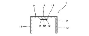
ところで、本実施例にかかる前記タペット1は、材質的には、「Ti-6AL-4V 」のチタン合金が使用されている。そして、図2に拡大して示すタペット1の形状、つまり、上端が閉塞された円筒状の形状を有し、また円筒状の筒部の肉厚はこの実施例では1mm〜2mm程度の厚さを有し、また、上端は1.5mm〜3mm程度の厚さを有し、さらに上端の内面に前記シム9(図1参照)と当接する肉厚部分(この実施例では前記上端の約2倍の厚さ)1Dを有する。前記厚みと形態を有するタペット1は、自動二輪車のエンジンのバルブ機構のタペット1としては、必要且つ十分な剛性を備え、且つ鋼製のものに比べて軽量化(約40%程度の軽量化)が図られている。しかしながら、タペット1は、前記形態(寸法)のものに限定されるものでなく、他の形態や寸法であっても、勿論よい。
By the way, the
そして、前述のような形状に加工されたタペット1の中間物(中間製品)に、以下に述べるような処理を施すことによって、軽量で、高負荷で且つ高速回転下での使用において高い耐久性を有するとともに、低摩擦抵抗の、タペット1を実現することができる。
The intermediate (intermediate product) of the
図2に示すような上端が閉塞された円筒状の形状に成形加工(鍛造加工、プレス加工や切削加工も含む)された中間物に対して、まず浸炭処理又は窒化処理を施す。この処理としては、種々考えられるが、例えば、プラズマ浸炭処理あるいはプラズマ窒化処理を、チタン合金の表面層の温度が500℃〜850℃の温度下で実施する(図2において浸炭加工を施した浸炭加工層14を太い黒線で示す)のが好ましい。前記温度が500℃以上であると炭素「C」又は窒素「N」が好ましい状態で拡散するとともに、850℃以下であると、熱処理による歪みが実質上問題の無い範囲に収めることができるからである。さらに言えば、歪みを可及的に小さくし且つ炭素「C」又は窒素「N」の拡散を担保しようとすると、温度条件としては、700℃〜800℃の温度下において処理することがより望ましい。
そして、このように浸炭加工又は窒化処理が施されることによって、耐磨耗性と耐焼付き性が付与される。
First, carburizing or nitriding is performed on an intermediate formed into a cylindrical shape with the upper end closed as shown in FIG. 2 (including forging, pressing, and cutting). For example, plasma carburizing treatment or plasma nitriding treatment is performed at a temperature of the surface layer of the titanium alloy of 500 ° C. to 850 ° C. (carburizing that has been carburized in FIG. 2). The processed
Then, by performing the carburizing process or the nitriding process in this way, wear resistance and seizure resistance are imparted.
また、前記浸炭処理として、プラズマ浸炭処理をおこなう場合には、図3に図示するような肉厚円筒状(パイプ状)の形態の治具20、つまり、図3に図示するような、前記シム9(図1参照)との接触面(前記肉厚部1Dの下面)1Bとなる部分(タペット1の上端内面の中央部分)と上端内面の角部1Rは本治具20によって閉塞されず、且つ、十分に下方からタペット1の上端を熱負荷に対して支持できるような支持面20Aを具備した形態の治具20が好ましい。つまり、このような形態の治具20を用いると、タペット1の外壁面(前記上面1Aと外周面1C)と該タペット1の上端の内面中央に位置する前記接触1Bが開放されているために、これらの箇所を浸炭処理によって硬化させることができる(図3の浸炭加工層14参照)とともに、上端内面の角部1Rが下方から支持されていないことから、その浸炭処理に際して、前記上面1Aのクラウニング形状(図3の中央部で上方にやや突出するような湾曲した太線および平行な二点鎖線で示す形状参照;図3の中太線は浸炭処理前の状態を示す:図1〜図2では、略図的に直線で表示している)に形成することが可能となる。
When the plasma carburizing process is performed as the carburizing process, the
次に、前記浸炭処理を施した前記円筒状のタペット1の中間物に対して、その外壁面の表面に形成されている酸化被膜を除去する。この酸化被膜除去処理として、例えば、研磨、エッチング、ショットブラスト、ショットピーニング、あるいはスパッタリングのいずれかの処理手法等によって、実施することが好ましい。いずれの処理方法を採用するかは、既存の設備としていずれの処理が適当か等の判断によって選択すればよい。また、前記酸化被膜除去処理として、前記処理に代えて、他の処理であってもよい。
酸化被膜除去処理の信頼性から言えば、前記スパッタリング処理によることが望ましい。また、生産効率の点からは、前記研磨処理によることが望ましい。また、生産コストを重視する場合には、前記ショットブラスト処理によることが望ましい。 また、前記酸化被膜の除去処理およびそれに続く下記のDLC膜の形成に際しては、除去した後に酸化被膜が形成されないように、真空雰囲気あるいは窒素雰囲気、水素雰囲気等の雰囲気中で処理される。
Next, the oxide film formed on the surface of the outer wall surface of the intermediate product of the
In terms of the reliability of the oxide film removal process, the sputtering process is preferable. From the viewpoint of production efficiency, it is preferable to use the polishing process. Further, when the production cost is important, it is desirable to use the shot blasting process. Further, when the oxide film is removed and the following DLC film is subsequently formed, the oxide film is treated in an atmosphere such as a vacuum atmosphere, a nitrogen atmosphere, or a hydrogen atmosphere so that the oxide film is not formed after the removal.
次に、表面の酸化被膜除去がおこなわれたタペット1の中間物の外壁面に、DLC膜15(図2参照)を形成する。このDLC膜の形成は、大別して、物理的蒸着法と化学的蒸着法との二つの手法があるが、いずれの手法でおこなってもよい。
しかし、物理的蒸着法の場合には、処理温度の低温化の点において好ましく、化学的蒸着法の場合には、三次元形状への所謂「つきまわり性(複雑な形状でも全面にムラ無く付くことをいう)」の点において優れている。
Next, the DLC film 15 (see FIG. 2) is formed on the outer wall surface of the intermediate of the
However, in the case of the physical vapor deposition method, it is preferable from the viewpoint of lowering the processing temperature, and in the case of the chemical vapor deposition method, the so-called “throwing ability to a three-dimensional shape (even in a complex shape, the entire surface is evenly attached). It is excellent in terms of “
そして、上述のように処理された本実施例にかかるタペット1は、前記浸炭処理(プラズマ浸炭処理)によって、硬度が550HV以上となり、その有効硬化深さ(浸炭処理層の厚さ)が0.02mm〜0.04mmであり、浸炭処理された表面の硬度は750HV〜1050HVになる。
そして、DLC膜形成後には、DLC膜の厚みが1μm〜3μmで、その表面硬さは1000HV〜1500HVになっている。そして、この実施例では、タペット1の表面粗度は、Ry1.6μmとなっている。
And the
After the DLC film is formed, the DLC film has a thickness of 1 μm to 3 μm and a surface hardness of 1000 HV to 1500 HV. In this embodiment, the surface roughness of the
そして、このように構成された本実施例にかかるタペット1は、シリンダヘッド30のタペット孔31と接触するタペット1の外周面1Cが前述のように表面にDLC膜15が形成されるとともに、その下層部分に浸炭処理が施されており、また、前記前記カム10と接触するタペット1の上面1Aにも前記DLC膜15の形成と浸炭処理が施されており、さらに前記タペット1のシム9との接触面1Bには浸炭処理が施されているため、また、前記DLC膜15の形成の前に、浸炭処理層14表面の酸化被膜の除去がなされた状態で、該DLC膜15の形成が、おこなわれているため、高負荷で高速回転下においても、極めて高い耐久性を有するとともに、摩擦抵抗も極めて小さく、しかも全体の重量が従来のものに比べて60パーセント程度となるため、高速回転仕様のエンジンにとって、さらなる高速化に寄与する、好ましいタペット1となる。
In the
ところで、前記実施例は、自動二輪車のエンジンのタペットについて本発明を適用した場合を例に挙げて説明したが、自動二輪車以外のエンジンであってもよく、また、エンジンの他の部材、例えば、前記バルブ、バルブスプリングシート、バルブガイドや、図示しないエンジンのコンロッドやその他のエンジンの構造物、あるいは自動二輪車のフロントフォーク等にも広く適用することができる。また、エンジン以外の部材、例えば、排気タービンやその他の軸、特に高速回転するような軸、あるいは一般の機械装置の部材にも適用することができ、前述したのと同様の作用効果を奏することができる。 By the way, although the said Example gave and demonstrated the case where the present invention was applied about the tappet of the engine of a motorcycle as an example, it may be an engine other than a motorcycle, and other members of an engine, for example, The present invention can be widely applied to the valve, the valve spring seat, the valve guide, the connecting rod of the engine (not shown), other engine structures, or the front fork of a motorcycle. It can also be applied to members other than engines, such as exhaust turbines and other shafts, particularly shafts that rotate at high speed, or members of general mechanical devices, and have the same effects as described above. Can do.
本願発明は、自動二輪車等のエンジンやその他一般の機械装置等に広く利用することができる。 The present invention can be widely used for engines such as motorcycles and other general mechanical devices.
1…タペット(チタン合金からなる部材)
1A…上面(摺動する表面)
2…バルブ
10…カム
1 ... Tappet (member made of titanium alloy)
1A ... Upper surface (sliding surface)
2 ... Valve
10 ... Cam
Claims (2)
前記チタン合金製の部材がタペットであり、該タペットを有底筒状の形態に形成するとともに、
該タペットの内壁面に、その角部と上端内面中央部を除いて当接する治具を配置した状態で、
このタペットの少なくとも摺動する部分の表面に、前記表面硬化処理の一種である浸炭処理又は窒化処理を施し、しかる後に前記ダイヤモンドライク・カーボン膜を形成したことを特徴とするチタン合金製の部材の製造方法。 A member made of a titanium alloy that is used as a machine part and has a diamond-like carbon film formed on a friction surface. The diamond-like carbon film is used as a pretreatment for forming the diamond-like carbon film. Is a method of manufacturing a member made of a titanium alloy that has been subjected to surface hardening treatment at a site where
The titanium alloy member is a tappet, and the tappet is formed into a bottomed cylindrical shape,
In a state where a jig that comes into contact with the inner wall surface of the tappet except for its corners and the central portion of the upper end inner surface is arranged,
A member made of a titanium alloy, wherein the surface of at least the sliding portion of the tappet is subjected to carburizing treatment or nitriding treatment which is a kind of surface hardening treatment, and then the diamond-like carbon film is formed. Production method.
Priority Applications (2)
| Application Number | Priority Date | Filing Date | Title |
|---|---|---|---|
| JP2005075567A JP4541941B2 (en) | 2005-03-16 | 2005-03-16 | Parts such as titanium alloy tappets and manufacturing method thereof |
| US11/377,241 US7621244B2 (en) | 2005-03-16 | 2006-03-15 | Titanium alloy tappet, manufacturing method thereof, and jig used in manufacturing tappet |
Applications Claiming Priority (1)
| Application Number | Priority Date | Filing Date | Title |
|---|---|---|---|
| JP2005075567A JP4541941B2 (en) | 2005-03-16 | 2005-03-16 | Parts such as titanium alloy tappets and manufacturing method thereof |
Publications (3)
| Publication Number | Publication Date |
|---|---|
| JP2006257942A JP2006257942A (en) | 2006-09-28 |
| JP2006257942A5 JP2006257942A5 (en) | 2008-01-17 |
| JP4541941B2 true JP4541941B2 (en) | 2010-09-08 |
Family
ID=37097492
Family Applications (1)
| Application Number | Title | Priority Date | Filing Date |
|---|---|---|---|
| JP2005075567A Expired - Fee Related JP4541941B2 (en) | 2005-03-16 | 2005-03-16 | Parts such as titanium alloy tappets and manufacturing method thereof |
Country Status (2)
| Country | Link |
|---|---|
| US (1) | US7621244B2 (en) |
| JP (1) | JP4541941B2 (en) |
Families Citing this family (5)
| Publication number | Priority date | Publication date | Assignee | Title |
|---|---|---|---|---|
| JP2007146731A (en) * | 2005-11-25 | 2007-06-14 | Yamaha Motor Co Ltd | Engine and vehicle |
| DE102008043993B3 (en) * | 2008-11-21 | 2010-04-29 | Thielert Aircraft Engines Gmbh | Common-rail high-pressure pump |
| JP2010261473A (en) | 2009-04-30 | 2010-11-18 | Yamaha Motor Co Ltd | Sliding component for internal combustion engine, internal combustion engine, transporter, and method for producing the sliding component for internal combustion engine |
| JP2012162998A (en) * | 2011-02-03 | 2012-08-30 | Toyota Motor Corp | Valve spring seat of internal combustion engine |
| US10006424B1 (en) * | 2016-12-22 | 2018-06-26 | GM Global Technology Operations LLC | Pump assembly and a propulsion system |
Citations (10)
| Publication number | Priority date | Publication date | Assignee | Title |
|---|---|---|---|---|
| JPH09264107A (en) * | 1996-03-27 | 1997-10-07 | Ngk Spark Plug Co Ltd | Tappet |
| JP2001131605A (en) * | 1999-11-08 | 2001-05-15 | Toyota Central Res & Dev Lab Inc | Method for manufacturing green compact, sintered- titanium valve lifter and its surface-treating method |
| JP2001140608A (en) * | 1999-11-15 | 2001-05-22 | Kawasaki Heavy Ind Ltd | Tappet |
| JP2002038912A (en) * | 1999-12-09 | 2002-02-06 | Sumitomo Electric Ind Ltd | Opening/closing mechanism of valve for internal combustion engine |
| JP2003041359A (en) * | 2001-07-30 | 2003-02-13 | Tanaka:Kk | Method for improving fatigue property of titanium alloy component, and titanium alloy component using the same |
| JP2003222143A (en) * | 2002-01-28 | 2003-08-08 | Nsk Ltd | Rolling sliding member |
| JP2004307894A (en) * | 2003-04-03 | 2004-11-04 | Air Water Inc | Method for manufacturing corrosion resistant, abrasion resistant and non-magnetic metal product, and corrosion resistant, abrasion resistant non-magnetic metal product obtained thereby |
| JP2004308851A (en) * | 2003-04-10 | 2004-11-04 | Matsushita Electric Ind Co Ltd | Dynamic pressure bearing motor and rotating device |
| JP2004307927A (en) * | 2003-04-07 | 2004-11-04 | Nissan Motor Co Ltd | Method for manufacturing sliding member, and sliding member |
| JP2005002801A (en) * | 2003-06-09 | 2005-01-06 | Aisan Ind Co Ltd | Valve lifter made from titanium alloy and its surface treatment method |
Family Cites Families (7)
| Publication number | Priority date | Publication date | Assignee | Title |
|---|---|---|---|---|
| DE3920729A1 (en) * | 1989-06-24 | 1991-01-10 | Gmb Giesserei & Maschinenbau B | CUPS FOR BOTTLE VALVES |
| US5249554A (en) * | 1993-01-08 | 1993-10-05 | Ford Motor Company | Powertrain component with adherent film having a graded composition |
| JPH1018023A (en) * | 1996-07-04 | 1998-01-20 | Toyota Motor Corp | Production of sliding member |
| WO1999047810A1 (en) * | 1998-03-19 | 1999-09-23 | Sumitomo Electric Industries, Ltd. | Combination of shim and cam |
| JPH11280419A (en) * | 1998-03-31 | 1999-10-12 | Sumitomo Electric Ind Ltd | Combination body of shim and cam |
| JP3051404B1 (en) | 1999-05-19 | 2000-06-12 | 川崎重工業株式会社 | Tappet |
| EP1450008B1 (en) * | 2002-09-27 | 2013-02-20 | Nissan Motor Company Limited | Automobile engine valve mechanism system shim and lifter, and combination of these and cam shaft |
-
2005
- 2005-03-16 JP JP2005075567A patent/JP4541941B2/en not_active Expired - Fee Related
-
2006
- 2006-03-15 US US11/377,241 patent/US7621244B2/en not_active Expired - Fee Related
Patent Citations (10)
| Publication number | Priority date | Publication date | Assignee | Title |
|---|---|---|---|---|
| JPH09264107A (en) * | 1996-03-27 | 1997-10-07 | Ngk Spark Plug Co Ltd | Tappet |
| JP2001131605A (en) * | 1999-11-08 | 2001-05-15 | Toyota Central Res & Dev Lab Inc | Method for manufacturing green compact, sintered- titanium valve lifter and its surface-treating method |
| JP2001140608A (en) * | 1999-11-15 | 2001-05-22 | Kawasaki Heavy Ind Ltd | Tappet |
| JP2002038912A (en) * | 1999-12-09 | 2002-02-06 | Sumitomo Electric Ind Ltd | Opening/closing mechanism of valve for internal combustion engine |
| JP2003041359A (en) * | 2001-07-30 | 2003-02-13 | Tanaka:Kk | Method for improving fatigue property of titanium alloy component, and titanium alloy component using the same |
| JP2003222143A (en) * | 2002-01-28 | 2003-08-08 | Nsk Ltd | Rolling sliding member |
| JP2004307894A (en) * | 2003-04-03 | 2004-11-04 | Air Water Inc | Method for manufacturing corrosion resistant, abrasion resistant and non-magnetic metal product, and corrosion resistant, abrasion resistant non-magnetic metal product obtained thereby |
| JP2004307927A (en) * | 2003-04-07 | 2004-11-04 | Nissan Motor Co Ltd | Method for manufacturing sliding member, and sliding member |
| JP2004308851A (en) * | 2003-04-10 | 2004-11-04 | Matsushita Electric Ind Co Ltd | Dynamic pressure bearing motor and rotating device |
| JP2005002801A (en) * | 2003-06-09 | 2005-01-06 | Aisan Ind Co Ltd | Valve lifter made from titanium alloy and its surface treatment method |
Also Published As
| Publication number | Publication date |
|---|---|
| US7621244B2 (en) | 2009-11-24 |
| JP2006257942A (en) | 2006-09-28 |
| US20060243237A1 (en) | 2006-11-02 |
Similar Documents
| Publication | Publication Date | Title |
|---|---|---|
| US7246586B2 (en) | Wear-resistant coating and process for producing it | |
| JP4541941B2 (en) | Parts such as titanium alloy tappets and manufacturing method thereof | |
| JP2010261473A (en) | Sliding component for internal combustion engine, internal combustion engine, transporter, and method for producing the sliding component for internal combustion engine | |
| JP3194982B2 (en) | Method of manufacturing engine valve lifter | |
| JP5311918B2 (en) | Spring retainer and spring system | |
| US20050284434A1 (en) | Slide member and method for producing the slide member | |
| JP2006257942A5 (en) | ||
| KR100540962B1 (en) | Sliding member and method of manufacturing thereof | |
| JP2006046123A (en) | Surface treatment method of valve lifter | |
| JP5898092B2 (en) | DRIVE CAM, MANUFACTURING METHOD THEREOF AND ENGINE VALVE DEVICE | |
| JP4372712B2 (en) | Titanium alloy valve lifter and manufacturing method thereof | |
| JP5744000B2 (en) | Sliding component for internal combustion engine, internal combustion engine, transport equipment, and method for manufacturing sliding component for internal combustion engine | |
| JP5342655B2 (en) | Connecting rod, single-cylinder internal combustion engine equipped with the same, and saddle riding type vehicle | |
| JP3939431B2 (en) | Valve mechanism of internal combustion engine | |
| US7308760B2 (en) | Method of making a valve lifter | |
| JPH0821216A (en) | Engine valve | |
| JP2005201295A (en) | Gear | |
| WO2014114414A1 (en) | Method for thermochemical diffusion treatment for a mechanical element, and corresponding mechanical element | |
| JP2736631B2 (en) | Sliding surface and surface treatment method | |
| JPH04171206A (en) | Valve retainer for internal combustion engine | |
| KR100643617B1 (en) | Method for Tungsten Carbide Carbon coating of tappet in engine | |
| JP2003222007A (en) | Lash adjuster | |
| JPH03249313A (en) | Intake/discharge valve for internal combustion engine | |
| JP2008215157A (en) | Engine valve | |
| JP4292099B2 (en) | Titanium alloy valve lifter for engine and manufacturing method thereof |
Legal Events
| Date | Code | Title | Description |
|---|---|---|---|
| A521 | Written amendment |
Free format text: JAPANESE INTERMEDIATE CODE: A523 Effective date: 20071127 |
|
| A621 | Written request for application examination |
Free format text: JAPANESE INTERMEDIATE CODE: A621 Effective date: 20071127 |
|
| A131 | Notification of reasons for refusal |
Free format text: JAPANESE INTERMEDIATE CODE: A131 Effective date: 20081216 |
|
| A521 | Written amendment |
Free format text: JAPANESE INTERMEDIATE CODE: A523 Effective date: 20090216 |
|
| A131 | Notification of reasons for refusal |
Free format text: JAPANESE INTERMEDIATE CODE: A131 Effective date: 20090818 |
|
| A521 | Written amendment |
Free format text: JAPANESE INTERMEDIATE CODE: A523 Effective date: 20091015 |
|
| A131 | Notification of reasons for refusal |
Free format text: JAPANESE INTERMEDIATE CODE: A131 Effective date: 20100406 |
|
| A521 | Written amendment |
Free format text: JAPANESE INTERMEDIATE CODE: A523 Effective date: 20100601 |
|
| TRDD | Decision of grant or rejection written | ||
| A01 | Written decision to grant a patent or to grant a registration (utility model) |
Free format text: JAPANESE INTERMEDIATE CODE: A01 Effective date: 20100622 |
|
| A01 | Written decision to grant a patent or to grant a registration (utility model) |
Free format text: JAPANESE INTERMEDIATE CODE: A01 |
|
| A61 | First payment of annual fees (during grant procedure) |
Free format text: JAPANESE INTERMEDIATE CODE: A61 Effective date: 20100624 |
|
| R150 | Certificate of patent or registration of utility model |
Free format text: JAPANESE INTERMEDIATE CODE: R150 |
|
| FPAY | Renewal fee payment (event date is renewal date of database) |
Free format text: PAYMENT UNTIL: 20130702 Year of fee payment: 3 |
|
| LAPS | Cancellation because of no payment of annual fees |