JP4541605B2 - Image processing apparatus and image processing method - Google Patents
Image processing apparatus and image processing method Download PDFInfo
- Publication number
- JP4541605B2 JP4541605B2 JP2001229644A JP2001229644A JP4541605B2 JP 4541605 B2 JP4541605 B2 JP 4541605B2 JP 2001229644 A JP2001229644 A JP 2001229644A JP 2001229644 A JP2001229644 A JP 2001229644A JP 4541605 B2 JP4541605 B2 JP 4541605B2
- Authority
- JP
- Japan
- Prior art keywords
- unit
- image processing
- image
- image data
- processing
- Prior art date
- Legal status (The legal status is an assumption and is not a legal conclusion. Google has not performed a legal analysis and makes no representation as to the accuracy of the status listed.)
- Expired - Fee Related
Links
Images


Landscapes
- Image Processing (AREA)
- Editing Of Facsimile Originals (AREA)
- Facsimile Image Signal Circuits (AREA)
- Record Information Processing For Printing (AREA)
Description
【0001】
【発明の属する技術分野】
本発明は、入力される画像データに画像処理を施し出力する画像処理装置及び画像処理方法に関する。
【0002】
【従来の技術】
複写機等の画像処理において、入力画像に対して輝度補正画像処理、色補正画像処理、回転処理、拡大縮小処理等、複数の画像処理を次々と施して出力画像を得るものがある。この画像処理は、汎用プロセッサを用いてソフトウェアで行う場合と、画像処理専用LSI等を用いてハードウェアで行う場合とがある。特に、高速な画像処理を行う用途に対しては、同じ処理速度性能においてコスト的に有利なハードウェアで行うことが一般的である。
【0003】
ハードウェアで画像処理を行う場合、画像全体を画素の単位に分割して、1画素または数画素ずつクロックに同期させて転送する方法が採られ、画素の単位に分割された画像は、数千あるいは数万といったクロック数の時間をかけて転送される。画像処理回路は、クロックパルス毎に入力される画素データを入力された順に処理して出力するという処理を行う。
【0004】
複数の画像処理を連続して実行する系の場合には、一つの画像処理部(画像処理回路)の画像出力端子が二つめの画像処理部の画像入力端子に接続されており、一つめの画像処理部の画像処理が施された画像は二つめの画像処理部に入力されて二つめの画像処理が施され、また同様に三つめ以降の画像処理部に次々と転送されて三つめ以降の画像処理が施される、という構成となる。
【0005】
この画像処理系においては、一つめの画像処理がすべて終了してから二つめの画像処理が開始されるのではなく、一つめの画像処理部は最初のいくつかの画素の画像処理が終了次第、処理が施された画素を出力し、二つめの画像処理部はその画素を受け取ると同時に画像処理を開始するという、すべての画像処理部が並列に、または、同時に動作するようになっており、高速に全体の画像処理が実行可能である。また、各画像処理部間に画像を記憶するための記憶装置が不必要だという特徴を持つ。ただし、この構成においては各画像処理部の順番は固定されていて、画像処理の順番を入れ替えることができない。
【0006】
そこで、各画像処理の順番の入れ替えを実現するために、各画像処理部を並列に配置し、さらに、画像処理の作業領域として画像全体が記憶できるだけの記憶部を持つカラー画像処理装置(特開平9−214755号公報)が提案されている。この構成によると、各画像処理の順番入れ替えの他に、一つの画像処理部の画像処理を複数回実行させることも可能となり、柔軟な画像処理が行えるようになる。
【0007】
【発明が解決しようとする課題】
しかしながら、前記カラー画像処理装置では、一つの画像処理が終了するまで次の画像処理を開始することができず、すべての画像処理部を同時に動作させる画像処理系と比較して全体の処理に時間がかかってしまう。さらに、画像一面分を記憶できるだけの記憶装置を画像処理装置内部に用意する必要があり、画像処理装置のコストが高くなってしまう。
【0008】
本発明は、上述した問題点を解決するためのものであり、複数の画像処理部を接続し各画像処理部間で画像データの転送を行う接続部を有し、入力される画像データに対して施すべき画像処理の順序に従い、複数の画像処理部が直列に接続されるように接続部の接続状態を切り換えることにより、コストアップを招くことなくかつ高速な画像処理を維持したまま、所望とする順序での画像処理を実行できるようにした画像処理装置及び画像処理方法を提供することを目的する。
【0010】
また、複数の画像処理部を接続し各画像処理部間で属性情報が付加された画像データの転送を行う接続部を有し、入力される画像データに付加された属性情報に従い接続部の接続状態を切り換えることにより、コストアップを招くことなくかつ高速な画像処理を維持したまま、所望の画像処理ためのCPU負荷を軽減することを可能とした画像処理装置及び画像処理方法を提供することを目的とする。
【0011】
【課題を解決するための手段】
上記目的を達成するために、本発明の画像処理装置は、入力される画像データに対して画像処理を施し出力する複数の画像処理手段と、前記複数の画像処理手段に含まれる2以上の画像処理手段を接続し、当該接続された画像処理手段間で画像データの転送を行う接続手段とを有し、前記入力される画像データに対して施すべき複数種類の画像処理の処理順序に従い、前記複数の画像処理手段に含まれる2以上の画像処理手段が直列に接続されるように前記接続手段の接続状態を切り換える画像処理装置であって、前記接続手段は、前記複数の画像処理手段又は装置外部それぞれから画像データを入力する複数の入力手段と、前記複数の入力手段により入力される複数の画像データから1つの画像データを選択する複数の選択手段と、前記複数の選択手段それぞれにより選択された画像データを、当該複数の選択手段それぞれに対応する画像処理手段又は装置外部に出力する複数の出力手段とを有し、前記接続手段の外部から、前記選択手段の選択設定を切り換え制御する制御手段をさらに有し、装置外部から入力され装置外部に出力される複数の画像データそれぞれに対して複数の画像処理を実行する際に、前記選択手段が選択する画像データを切り換えることにより、前記複数の画像処理手段に含まれる2以上の画像処理手段を直列に接続し、当該直列接続された画像処理手段が独立に複数個構成されるようにすることを特徴とする。
【0013】
また、本発明の画像処理装置は、画像データを入力する入力手段と、画像データに対して画像処理を実行する複数の画像処理手段と、前記複数の画像処理手段のうち何れか2つ以上を直列に接続する接続手段と、前記入力手段により複数の画像データが入力され、当該複数の画像データそれぞれが複数の画像処理手段による画像処理を必要とし、当該複数の画像データそれぞれが共通の画像処理手段による画像処理を必要としない場合に、当該複数の画像データそれぞれに対応して直列に接続される画像処理手段が独立して複数個構成されるように、前記接続手段を制御する制御手段とを有することを特徴とする。
【0014】
また、本発明の画像処理装置は、入力される画像データに対して画像処理を施し出力する複数の画像処理手段と、前記複数の画像処理手段に含まれる2以上の画像処理手段を接続し、当該接続された画像処理手段間で画像データの転送を行う接続手段とを有し、前記入力される画像データに対して施すべき複数種類の画像処理の処理順序に従い、前記複数の画像処理手段に含まれる2以上の画像処理手段が直列に接続されるように前記接続手段の接続状態を切り換える画像処理装置であって、前記接続手段は、前記複数の画像処理手段又は装置外部それぞれから画像データを入力する複数の入力手段と、前記複数の入力手段により入力される複数の画像データから1つの画像データを選択する複数の選択手段と、前記複数の選択手段それぞれにより選択された画像データを、当該複数の選択手段それぞれに対応する画像処理手段又は装置外部に出力する複数の出力手段とを有し、装置外部から入力され装置外部に出力される複数の画像データそれぞれに対して複数の画像処理を実行する際に、前記複数の画像データそれぞれが前記複数の画像処理手段のうち互いに異なる画像処理手段により画像処理が実行されるべきものである場合、前記選択手段が選択する画像データを切り換えることにより、前記複数の画像処理手段に含まれる2以上の画像処理手段を直列に接続し、当該直列接続された画像処理手段が独立に複数個構成されるようにして、前記複数の画像データそれぞれに対する画像処理を並行して実行することを特徴とする。
【0016】
また、本発明の画像処理方法は、画像データを入力する入力手段と、画像データに対して画像処理を実行する複数の画像処理手段と、前記複数の画像処理手段のうち何れか2つ以上を直列に接続する接続手段とを有する画像処理装置の画像処理方法であって、前記入力手段により複数の画像データが入力され、当該複数の画像データそれぞれが複数の画像処理手段による画像処理を必要とし、当該複数の画像データそれぞれが共通の画像処理手段による画像処理を必要としない場合に、当該複数の画像データそれぞれに対応して直列に接続される画像処理手段が独立して複数個構成されるように、前記接続手段を制御する制御工程を有することを特徴とする。
【0017】
【発明の実施の形態】
以下、図面を参照して本発明の実施の形態を説明する。
【0018】
(第1の実施形態)
図1は本発明を適用可能なデジタル複合機の構成を示すブロック図である。リーダ部1は原稿の画像を読み取り、原稿画像に応じた画像データをプリンタ部2及び画像入出力制御部3へ出力する。プリンタ部2はリーダ部1及び画像入出力制御部3からの画像データに応じた画像を記録紙上に記録する。画像入出力制御部3はリーダ部1に接続されており、ファクシミリ部4、ファイル部5、コンピュータインターフェイス部7、フォーマッタ部8、イメージメモリ部9、コア部10などからなる。
【0019】
ファクシミリ部4は電話回線を介して受信した圧縮画像データを伸長して、伸長された画像データをコア部10へ転送し、又、コア部10から転送された画像データを圧縮して、圧縮された圧縮画像データを電話回線を介して送信する。ファクシミリ部4にはハードディスク12が接続されており、受信した圧縮画像データを一時的に保存することができる。
【0020】
ファイル部5には光磁気ディスクドライブユニット6が接続されており、ファイル部5はコア部10から転送された画像データを圧縮し、その画像データを検索するためのキーワードとともに光磁気ディスクドライブユニット6にセットされた光磁気ディスクに記憶させる。又、ファイル部5はコア部10を介して転送されたキーワードに基づいて光磁気ディスクに記憶されている圧縮画像データを検索し、検索された圧縮画像データを読み出して伸長し、伸長された画像データをコア部10へ転送する。
【0021】
コンピュータインターフェイス部7は、パーソナルコンピュータ又はワークステーション(PC/WS)11とコア部10の間のインターフェイスである。フォーマッタ部8はPC/WS11から転送された画像を表すコードデータをプリンタ部2で記録できる画像データに展開するものであり、イメージメモリ部9はPC/WS11から転送されたデータを一時的に記憶するものである。
【0022】
コア部10については後述するが、コア部10はリーダ部1、ファクシミリ部4、ファイル部5、コンピュータインターフェイス部7、フォーマッタ部8、イメージメモリ部9のそれぞれの間のデータの流れを制御するものである。
【0023】
図2はリーダ部1及びプリンタ部2の断面図である。リーダ部1の原稿給送装置101は原稿を最終頁から順に1枚ずつプラテンガラス102上へ給送し、原稿の読み取り動作終了後、プラテンガラス102上の原稿を排出するものである。原稿がプラテンガラス102上に搬送されると、ランプ103を点灯し、そしてスキャナユニット104の移動を開始させて、原稿を露光走査する。この時の原稿からの反射光は、ミラー105、106、107、及びレンズ108によってCCDイメージセンサ(以下CCDという)109へ導かれる。このように、走査された原稿の画像はCCD109によって読み取られる。CCD109から出力される画像データは、所定の処理が施された後、プリンタ部2及び画像入出力制御部3のコア部10へ転送される。
【0024】
プリンタ部2のレーザドライバ221はレーザ発光部201を駆動するものであり、リーダ部1から出力された画像データに応じたレーザ光をレーザ発光部201に発光させる。このレーザ光は感光ドラム202に照射され、感光ドラム202にはレーザ光に応じた潜像が形成される。この感光ドラム202の潜像の部分には現像器203によって現像剤が付着される。そして、レーザ光の照射開始と同期したタイミングで、カセット204及びカセット205のいずれかから記録紙を給紙して転写部206へ搬送し、感光ドラム202に付着された現像剤を記録紙に転写する。現像剤の乗った記録紙は定着部207に搬送され、定着部207の熱と圧力により現像剤は記録紙に定着される。
【0025】
定着部207を通過した記録紙は排出ローラ208によって排出され、ソータ220は排出された記録紙をそれぞれのビンに収納して記録紙の仕分けを行う。なお、ソータ220は仕分けが設定されていない場合は最上ビンに記録紙を収納する。また、両面記録が設定されている場合は、排出ローラ208のところまで記録紙を搬送した後、排出ローラ208の回転方向を逆転させ、フラッパ209によって再給紙搬送路へ導く。多重記録が設定されている場合は、記録紙を排出ローラ208まで搬送しないようにフラッパ209によって再給紙搬送路へ導く。再給紙搬送路へ導かれた記録紙は上述したタイミングで転写部206へ給紙される。
【0026】
図3はリーダ部1のブロック図である。CCD109から出力された画像データはA/D・SH部110でアナログ/デジタル変換が行われるとともに、シェーディング補正が行われる。A/D・SH部110によって処理された画像データは画像処理部111を介してプリンタ部2へ転送されるとともに、インターフェイス部113を介して画像入出力制御部3のコア部10へ転送される。
【0027】
CPU114は操作部115で設定された設定内容に応じて画像処理部111及びインターフェイス113を制御する。例えば、操作部115でトリミング処理を行って複写を行う複写モードが設定されている場合は、画像処理部111でトリミング処理を行わせてプリンタ部2へ転送させる。また、操作部115でファクシミリ送信モードが設定されている場合は、インターフェイス113から画像データと設定されたモードに応じた制御コマンドをコア部10へ転送させる。このようなCPU114の制御プログラムはメモリ116に記憶されており、CPU114はメモリ116を参照しながら制御を行う。また、メモリ116はCPU114の作業領域としても使われる。
【0028】
図4はコア部10のブロック図である。リーダ部1からの画像データはデータ処理部121へ転送されるとともに、リーダ部1からの制御コマンドはCPU123へ転送される。データ処理部121は画像の回転処理や変倍処理などの画像処理を行うものであり、リーダ部1からデータ処理部121へ転送された画像データは、リーダ部1から転送された制御コマンドに応じて、インターフェイス120を介してファクシミリ部4、ファイル部5、コンピュータインターフェイス部7へ転送される。
【0029】
また、コンピュータインターフェイス7を介して入力された画像を表すコードデータは、データ処理部121に転送された後フォーマッタ部8へ転送されて画像データに展開され、この画像データはデータ処理部121に転送された後、ファクシミリ部4やプリンタ部2へ転送される。ファクシミリ部4からの画像データは、データ処理部121へ転送された後、プリンタ部2やファイル部5、コンピュータインターフェイス部7へ転送される。
【0030】
また、ファイル部5からの画像データは、データ処理部121へ転送された後、プリンタ部2やファクシミリ部4、コンピュータインターフェイス部7へ転送される。CPU123はメモリ124に記憶されている制御プログラム、及びリーダ部1から転送された制御コマンドに従ってこのような制御を行う。また、メモリ124はCPU123の作業領域としても使われる。このように、コア部10を中心に、原稿画像の読み取り、画像のプリント、画像の送受信、画像の保存、コンピュータからのデータの入出力などの機能を複合させた処理を行うことが可能である。
【0031】
図5はデータ処理部121のブロック図である。変倍処理部130、回転・反転処理部131、色変換処理部132、斜体文字処理部133、圧縮・伸長処理部134、および、圧縮・伸長処理部135は、CPU123によって制御され、入力画像データを変換処理して出力する画像処理部である。
【0032】
次に、これら画像処理部での画像処理を個別に説明する。変倍処理部130は入力された画像データを拡大、または、縮小処理して出力する画像処理部である。
【0033】
回転・反転処理部131は入力された画像データを、90度回転した画像に変換処理するか、180度回転した画像に変換処理するか、270度回転した画像に変換処理するか、左右を反転した画像に変換処理するか、左右を反転してさらに90度回転した画像に変換処理するか、左右を反転してさらに180度回転した画像に変換処理するか、左右を反転してさらに270度回転した画像に変換処理するか、または、入力された画像をそのまま変換しないか、これらいずれかの処理を選択して実行し、処理結果を出力する画像処理部である。
【0034】
色変換処理部132は入力された画像データの色濃度を演算処理して出力する画像処理部である。
【0035】
斜体文字処理部133は入力された画像データを斜体文字処理して出力する画像処理部である。ここで、斜体文字処理とは、画像に含まれる文字を右斜め斜体文字に変換する画像処理のことである。
【0036】
圧縮・伸長処理部134は入力された画像データを圧縮変換処理して画像符号データに変換するか、または、入力された画像符号データを伸長して画像データに変換する画像処理部である。
【0037】
圧縮・伸長処理部135は圧縮・伸長処理部134と同じ機能を持ち、圧縮・伸長処理部134の動作状態に関係なく独立に動作可能な画像処理部である。
【0038】
接続切換部136はCPU123によって制御される接続切換部であり、I/F部120、変倍処理部130、回転・反転処理部131、色変換処理部132、斜体文字処理部133、圧縮・伸長処理部134、圧縮・伸長処理部135、および、I/F部122の持つ画像データ入力端子と画像データ出力端子とを接続して各画像処理部間の画像データの流れを制御する部分である。
【0039】
次に、データ処理部121での画像データの流れを説明する。リーダ部1からの画像データはインターフェイス122を介してデータ処理部121に転送される。また、ファクシミリ部4、ファイル部5、フォーマッタ部8、イメージメモリ部9からの画像データはインターフェイス120を介してデータ処理部121に転送される。
【0040】
データ処理部121では、入力された画像データはまず接続切換部136に入力される。そしてその画像データは、CPU123の制御により、変倍処理部130、回転・反転処理部131、色変換処理部132、斜体文字処理部133、圧縮・伸長処理部134、圧縮・伸長処理部135、I/F部120、または、I/F部122、のうちいずれかの画像処理部またはI/F部に対して出力される。
【0041】
変倍処理部130、回転・反転処理部131、色変換処理部132、斜体文字処理部133、圧縮・伸長処理部134、または、圧縮・伸長処理部135、のうちいずれかの画像処理部に対して出力された画像データは、該画像処理部でCPU123の制御による画像処理が施された後、再度、接続切換部136に入力される。
【0042】
そして、また同様に、その画像データは、CPU123の制御により、変倍処理部130、回転・反転処理部131、色変換処理部132、斜体文字処理部133、圧縮・伸長処理部134、圧縮・伸長処理部135、I/F部120、または、I/F部122、のうちいずれかの画像処理部またはI/F部に対して出力される。
【0043】
このように、CPU123の制御により、複数の画像処理部での画像処理を任意の順番で任意の回数繰り返すことにより、画像データに対して所望の画像処理を施してからI/F部120またはI/F部122に出力することが可能な構成となっている。
【0044】
図6は接続切換部136のブロック図である。I/F部120から入力された画像データは、CPU123の制御で接続切換部136内部のセレクタを切り換えることにより、I/F部120、変倍処理部130、回転・反転処理部131、色変換処理部132、斜体文字処理部133、圧縮・伸長処理部134、圧縮・伸長処理部135、または、I/F部122、のうちいずれかの画像処理部またはI/F部に対して出力される。
【0045】
同様に、変倍処理部130から入力された画像データは、CPU123の制御で接続切換部136内部のセレクタを切り換えることにより、I/F部120、変倍処理部130、回転・反転処理部131、色変換処理部132、斜体文字処理部133、圧縮・伸長処理部134、圧縮・伸長処理部135、または、I/F部122、のうちいずれかの画像処理部またはI/F部に対して出力される。
【0046】
また、さらに、回転・反転処理部131、色変換処理部132、斜体文字処理部133、圧縮・伸長処理部134、圧縮・伸長処理部135、および、I/F部122、から入力された画像データについても同様に、CPU123の制御で接続切換部136内部のセレクタを切り換えることにより、I/F部120、変倍処理部130、回転・反転処理部131、色変換処理部132、斜体文字処理部133、圧縮・伸長処理部134、圧縮・伸長処理部135、または、I/F部122、のうちいずれかの画像処理部またはI/F部に対して出力される。
【0047】
CPU123は、画像データに対して所望の画像処理が実現できるように、接続切換部136内部のセレクタを制御し、各画像処理部およびI/F部を接続する。
【0048】
以下、データ処理部121において、複数の画像処理部を任意の順番で利用して、入力された画像データに対して所望の画像処理を施す手順を示す。
【0049】
ここで、コア部10に入力される画像は、ファクシミリ部4、ファイル部5、コンピュータインターフェイス部7、フォーマッタ部8、イメージメモリ部9、また、リーダ部1のいずれから入力されて、I/F部120またはI/F部122いずれかのI/F部を介してデータ処理部121に入力される。
【0050】
また、コア部10から出力される画像は、I/F部120またはI/F部122いずれかのI/F部を介してファクシミリ部4、ファイル部5、コンピュータインターフェイス部7、フォーマッタ部8、イメージメモリ部9、または、リーダ部1に対して出力される。
【0051】
つまり、入出力装置の種類が数多いため、様々な画像データの流れが存在する。また、データ処理部121での画像処理内容は、画像処理に使用する画像処理部とその接続順序の組み合わせが多いため、様々な画像処理内容が存在する。
【0052】
しかしながら、データ処理部121における画像の流れだけを見ると、コア部10の外側に接続されている画像出力手段および画像入力手段が何であっても同じである。さらに、データ処理部121では、各画像処理部の組み合わせと処理順序により数多くの画像処理が実現可能であるが、各画像処理部はどれも、入力された画像データに対して画像処理変換を施して出力する、という点で同じであり、接続切換部136での各画像処理部の接続も各画像処理部について相対的に同じである。
【0053】
そのため一般性を失わずに、以下では、数多くの画像データの流れと画像処理内容の中から代表して、入力される画像データはファクシミリ部4からI/F部120を経由してデータ処理部121に入力されて、データ処理部121で所望の画像処理が施されて、I/F部120を経由してイメージメモリ部9に転送されるときで、所望の画像処理とは、伸長処理、斜体文字処理、反転処理、という順番の画像処理であるときを例にとって説明する。
【0054】
以下、この画像処理例を例1と記述する。まず、所望の画像処理を実現する画像処理部は、処理順に、圧縮・伸長処理部134、斜体文字処理部133、回転・反転処理部131、である。
【0055】
したがって、CPU123の制御により、接続切換部136内部のセレクタ142の入力はI/F部120からの出力信号を選択し、セレクタ141の入力は圧縮・伸長処理部134からの出力信号を選択し、セレクタ139の入力は斜体文字処理部133からの出力信号を選択し、セレクタ137の入力は回転・反転処理部131からの出力信号を選択した状態に設定される。また、その他のセレクタは、CPU123の制御により、何も信号が出力されない状態に設定される。
【0056】
そして、CPU123の制御により、I/F部120、圧縮・伸長処理部134、斜体文字処理部133、回転・反転処理部131の動作が開始される。I/F部120はファクシミリ部4に画像データの転送を開始するように制御信号を送信し、ファクシミリ部4はその制御信号に応じて、I/F部120部に対して画像データの転送を開始する。
【0057】
I/F部120は受信した画像データを接続切換部136に対して送信し、画像データはセレクタ142を介して圧縮・伸長処理部134に対して送信される。
【0058】
圧縮・伸長処理部134は受信した画像データをCPU123の制御により伸長処理し、接続切換部136に対して送信し、画像データはセレクタ141を介して斜体文字処理部133に対して送信される。
【0059】
斜体文字処理部133は受信した画像データをCPU123の制御により斜体文字処理し、接続切換部136に対して送信し、画像データはセレクタ139を介して回転・反転処理部131に対して送信される。
【0060】
回転・反転処理部131は受信した画像データをCPU123の制御により反転処理し、接続切換部136に対して送信し、画像データはセレクタ137を介してI/F部120に送信される。
【0061】
I/F部120は受信した画像データをCPU123の制御によりイメージメモリ部9に対して転送する。イメージメモリ部9は、受信した画像データを内部メモリに蓄積する。
【0062】
このようにして、CPU123の制御で、接続切換部136内部のセレクタの設定を変更することにより、複数の画像処理部を任意の順番で使用して所望の画像処理を実現することが可能である。
【0063】
なお、本実施形態では、本願従来の技術で述べた通り、画像全体を画素の単位に分割して、1画素または数画素ずつクロックに同期させて転送する方法を採用し、画素の単位に分割した画像を、数千あるいは数万といったクロック数の時間をかけて転送する。そして、各画像処理部は、クロックパルス毎に入力される画素データを、入力された順に処理して出力するという処理を行う。
【0064】
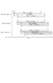
具体的には、各画像処理部では、画像データ中の先頭のいくつかの画素データが入力されると即座にその画素データに対して画像処理を施し、その処理結果の画素データを即座に出力する。そのため、ある一つの画像処理部に注目して、画像データの入力転送を実行している時間と画像処理を実行している時間と出力転送を実行している時間について図示すると、図7のようになる。
【0065】
この図示方法によって、前述の例1における一連の画像処理動作時の各画像処理部での画像データの転送実行時間および画像処理実行時間を図示すると、図8のようになる。各画像処理部での画像処理が同時に動作しており、前段の画像処理が終了するのを待たずに後段の画像処理が開始されていることが示されている。この方式により、前述のように複数の画像処理を実行した場合でも、すべての画像処理が終了するまでの処理時間がかかり過ぎるのを防ぐことが可能となっている。
【0066】
ここで、前述の例1における一連の画像処理動作後にさらにもう一度圧縮・伸長処理部134を利用して画像データの圧縮処理を追加した新しい一連の画像処理を考える。以下、この画像処理例を例2と記述する。この例2における一連の画像処理動作の各画像処理部での各処理の実行時間を図示すると図9のようになるが、この例2における一連の画像処理は実行不可能であることが判る。
【0067】
なぜかというと、圧縮・伸長処理部134には画像入力端子は一つしかないが、図9のア点からウ点の間において、二つの画像データを入力しなければいけないことになっているからである。また、圧縮・伸長処理部134には画像処理回路は一つしかないが、図9のア点からエ点の間において、二つの画像データの画像処理を行わなければいけないことになっているからである。さらに、圧縮・伸長処理部134には画像出力端子は一つしかないが、図9のイ点からエ点の間において、二つの画像データを出力しなければいけないことになっているからである。
【0068】
つまり、これは、本実施形態では、通常、同一の画像処理部を複数回繰り返して使用するような一連の画像処理は実行不可能であることを示している。したがって、これを解決するために、CPU123は現在使用していない別の画像処理部を常に選択するように制御することになる。
【0069】
この例においては、圧縮処理を実行するために新たに追加する圧縮・伸長処理部として圧縮・伸長処理部134ではなく、圧縮・伸長処理部135を利用することで、一連の画像処理が図10に示す通り実行可能となる。このときの接続切換部136内部のセレクタの設定で前述と異なるところは、セレクタ137の入力は圧縮・伸長処理部135からの出力信号を選択し、セレクタ143の入力は回転・反転処理部131からの出力信号を選択するというところである。
【0070】
また、前述の図8で示した例1において、斜体文字処理と、反転処理との順番を入れ替えて、反転処理をした後に斜体文字処理を行うような新しい一連の画像処理を考える。したがって、新しい一連の画像処理とは、伸長処理、反転処理、斜体文字処理、という順番の画像処理である。以下、この一連の画像処理例を例3と記述する。
【0071】
この例3の場合には、CPU123は、接続切換部136内部のセレクタの設定を前述の図8で示した例1の場合と少しだけ変更する。つまり、セレクタ139の入力は回転・反転処理部131からの出力信号を選択し、セレクタ137の入力は斜体文字処理部133からの出力信号を選択した状態に設定するというところだけ変更する。
【0072】
この変更によって、新しい一連の画像処理例3が実現でき、その各画像処理部での各処理の実行時間を図11に示す。また、図12で示す入力画像に対して、図8に対応する一連の画像処理例1を施した結果の画像を図13に示し、図12で示す入力画像に対して、図11に対応する一連の画像処理例3を施した結果の画像を図14に示す。
【0073】
画像処理の順序を変更することで、画像処理結果が変化することを示している。なお、データ処理部121に対して入力される画像データは伸長処理前の圧縮されたままの画像データであり、図にしても画像として認識できるものではないので、ここでは便宜的に伸長処理した後の画像を図12として載せてある。
【0074】
以上のように、本実施形態では、接続切換部136が、同時に画像処理動作が可能な複数の画像処理部130〜135の、すべての画像データ入出力端子と接続する構成とした。そして、設定により接続切換部136の内部接続状態を変化させて、接続されたすべての画像処理部130〜135の中の一部または全部を回路的に直列に繋げることができるようにした。
【0075】
そして、CPU部123は、複数の画像処理部130〜135の中から使用する画像処理部を選択し、選択された画像処理部の実行順序を接続切換部136に設定することで、入力された画像データに対して施す画像処理の順序を設定、変更することを可能とした。
【0076】
これにより、後段の画像処理部の処理を前段の画像処理部の処理が終了するまで待たずに開始できるという高速な画像処理を維持したまま、実行したい画像処理だけを実行したい順序に接続して全体として所望の画像処理を実現するという柔軟な画像処理が実現可能となる。
【0077】
また、各画像処理部間に一時的に画像を保持しておくバッファ等も必要としないので、装置のコストアップを回避することができる。
【0078】
また、CPU部123が、一度の画像処理動作において一つの画像処理部を複数回使用しないことにより、画像処理内容が同一であるが同時に複数回実行させたい画像処理部が存在する場合にも、その画像処理に対応する画像処理部を複数個使用するように制御するようにした。
【0079】
これにより同一の画像処理を一度に複数回実行させることが可能であり、柔軟で、かつ、より高速な画像処理が実現可能となる。
【0080】
(第2の実施形態)
第1の実施形態では、複数の画像処理部を持つデータ処理部121において、画像データ入力端子と画像データ出力端子がそれぞれ一つしかないため、複数の画像データを同時に入力、処理、出力することができない。例えば、画像データXに対して画像処理部Aで画像処理を施して出力しながら、同時に、別の画像データYに対して画像処理部Bで画像処理を施して出力するということができなかった。
【0081】
したがって、どちらかの画像データを先に画像処理して、その処理が完全に終了した後に次の画像データに対しての画像処理を開始することになりすべての処理終了までに時間がかかってしまう。
【0082】
本実施形態では、画像データ入力端子から画像データ出力端子に対しての画像処理回路を複数構成することで、同時に複数の画像データに対する独立な複数の画像処理が実行可能とする。
【0083】
図15は、本実施形態におけるコア部10のブロック図である。データ処理部121はI/F部を介して周辺装置と接続され、それぞれ専用のI/F部を介した画像データのやりとりを行う。
【0084】
図で示すように、データ処理部121とリーダ部1との間での画像データの入出力転送はI/F部122を介し、データ処理部121とファクシミリ4との間での画像データの入出力転送はI/F部125を介し、データ処理部121とファイル部5との間での画像データの入出力転送はI/F部126を介し、データ処理部121とコンピュータインターフェイス部7との間での画像データの入出力転送はI/F部127を介し、データ処理部121とフォーマッタ部8との間での画像データの入出力転送はI/F部128を介し、データ処理部121とイメージメモリ部9との間での画像データの入出力転送はI/F部129を介して行う。
【0085】
次に、画像データの流れの例を挙げる。リーダ部1からの画像データはデータ処理部121へ転送されるとともに、リーダ部1からの制御コマンドはCPU123へ転送される。データ処理部121は画像の回転処理や変倍処理などの画像処理を行うものであり、リーダ部1からデータ処理部121へ転送された画像データは、リーダ部1から転送された制御コマンドに応じて、ファクシミリ部4、ファイル部5、コンピュータインターフェイス部7へ転送される。
【0086】
また、コンピュータインターフェイス7を介して入力された画像を表すコードデータは、データ処理部121に転送された後フォーマッタ部8へ転送されて画像データに展開され、この画像データは再度データ処理部121に転送された後、ファクシミリ部4やプリンタ部2へ転送される。
【0087】
ファクシミリ部4からの画像データは、データ処理部121へ転送された後、プリンタ部2やファイル部5、コンピュータインターフェイス部7へ転送される。
【0088】
また、ファイル部5からの画像データは、データ処理部121へ転送された後、プリンタ部2やファクシミリ部4、コンピュータインターフェイス部7へ転送される。
【0089】
CPU123はメモリ124に記憶されている制御プログラム、及びリーダ部1から転送された制御コマンドに従ってこのような制御を行う。また、メモリ124はCPU123の作業領域としても使われる。このように、コア部10を中心に、原稿画像の読み取り、画像のプリント、画像の送受信、画像の保存、コンピュータからのデータの入出力などの機能を複合させた処理を行うことが可能である。
【0090】
図16はデータ処理部121のブロック図である。変倍処理部130、回転・反転処理部131、色変換処理部132、斜体文字処理部133、圧縮・伸長処理部134、および、圧縮・伸長処理部135は、第1の実施形態で説明したものと同様な画像処理部であり、CPU123によって制御され、入力画像データを変換処理して出力する画像処理部である。
【0091】
次に、データ処理部121での画像データの流れを説明する。リーダ部1からの画像データはI/F部122を介してデータ処理部121に転送される。また、ファクシミリ部4、ファイル部5、フォーマッタ部8、イメージメモリ部9からの画像データはそれぞれI/F部125、I/F部126、I/F部127、I/F部128、I/F部129を介してデータ処理部121に転送される。
【0092】
データ処理部121では、入力された画像データはまず接続切換部136に入力される。そしてその画像データは、CPU123の制御により、変倍処理部130、回転・反転処理部131、色変換処理部132、斜体文字処理部133、圧縮・伸長処理部134、圧縮・伸長処理部135、I/F部122、I/F部125、I/F部126、I/F部127、I/F部128、または、I/F部129、のうちいずれかの画像処理部またはI/F部に対して出力される。
【0093】
変倍処理部130、回転・反転処理部131、色変換処理部132、斜体文字処理部133、圧縮・伸長処理部134、または、圧縮・伸長処理部135、のうちいずれかの画像処理部に対して出力された画像データは、該画像処理部でCPU123の制御による画像処理が施された後、再度、接続切換部136に入力される。
【0094】
そして、また同様に、その画像データは、CPU123の制御により、変倍処理部130、回転・反転処理部131、色変換処理部132、斜体文字処理部133、圧縮・伸長処理部134、圧縮・伸長処理部135、I/F部122、I/F部125、I/F部126、I/F部127、I/F部128、または、I/F部129、のうちいずれかの画像処理部またはI/F部に対して出力される。
【0095】
このように、CPU123の制御により、複数の画像処理部での画像処理を任意の順番で任意の回数繰り返すことにより、画像データに対して所望の画像処理を施してからいずれかのI/F部に出力することが可能な構成となっている。
【0096】
図17は接続切換部136のブロック図である。I/F部122から入力された画像データは、CPU123の制御で接続切換部136内部のセレクタを切り換えることにより、I/F部122、I/F部125、I/F部126、I/F部127、I/F部128、I/F部129、変倍処理部130、回転・反転処理部131、色変換処理部132、斜体文字処理部133、圧縮・伸長処理部134、または、圧縮・伸長処理部135、のうちいずれかの画像処理部またはI/F部に対して出力される。
【0097】
同様に、I/F部125から入力された画像データは、CPU123の制御で接続切換部136内部のセレクタを切り換えることにより、I/F部122、I/F部125、I/F部126、I/F部127、I/F部128、I/F部129、変倍処理部130、回転・反転処理部131、色変換処理部132、斜体文字処理部133、圧縮・伸長処理部134、または、圧縮・伸長処理部135、のうちいずれかの画像処理部またはI/F部に対して出力される。
【0098】
また、さらに、I/F部126、I/F部127、I/F部128、I/F部129、変倍処理部130、回転・反転処理部131、色変換処理部132、斜体文字処理部133、圧縮・伸長処理部134、および、圧縮・伸長処理部135、から入力された画像データについても同様に、CPU123の制御で接続切換部136内部のセレクタを切り換えることにより、I/F部122、I/F部125、I/F部126、I/F部127、I/F部128、I/F部129、変倍処理部130、回転・反転処理部131、色変換処理部132、斜体文字処理部133、圧縮・伸長処理部134、または、圧縮・伸長処理部135、のうちいずれかの画像処理部またはI/F部に対して出力される。
【0099】
CPU123は、画像データに対して所望の画像処理が実現できるように、接続切換部136内部のセレクタを制御し、各画像処理部およびI/F部を接続する。
【0100】
以下、データ処理部121において、複数の画像処理部を任意の順番で利用して、入力された画像データに対して所望の画像処理を施す手順を示す。
【0101】
ここで、コア部10に入力される画像は、ファクシミリ部4、ファイル部5、コンピュータインターフェイス部7、フォーマッタ部8、イメージメモリ部9、また、リーダ部1のいずれから入力されて、I/F部を介してデータ処理部121に入力される。
【0102】
また、コア部10から出力される画像は、I/F部を介してファクシミリ部4、ファイル部5、コンピュータインターフェイス部7、フォーマッタ部8、イメージメモリ部9、または、リーダ部1に対して出力される。
【0103】
つまり、入出力装置の種類が数多いため、様々な画像データの流れが存在する。また、データ処理部121での画像処理内容は、画像処理に使用する画像処理部とその接続順序の組み合わせが多いため、様々な画像処理内容が存在する。
【0104】
しかしながら、データ処理部121における画像の流れだけを見ると、コア部10の外側に接続されている画像出力手段および画像入力手段が何であっても、いずれかのI/F部を介して画像データが入力され、いずれかのI/F部を介して画像データが出力されるという点において、同じ一つの画像の流れとして考えることができる。
【0105】
さらに、データ処理部121では、各画像処理部の組み合わせと処理順序により数多くの画像処理が実現可能であるが、各画像処理部はどれも、入力された画像データに対して画像処理変換を施して出力する、という点で同じであり、接続切換部136での各画像処理部の接続も各画像処理部について相対的に同じである。
【0106】
そのため一般性を失わずに、以下では、数多くの画像データの流れと画像処理内容の中から代表して、入力される画像データはファクシミリ部4からI/F部125を経由してデータ処理部121に入力されて、データ処理部121で所望の画像処理が施されて、I/F部129を経由してイメージメモリ部9に転送されるときで、所望の画像処理とは、伸長処理、斜体文字処理、反転処理、という順番の画像処理であるときを例にとって説明する。以下、この画像処理例を例4と記述する。
【0107】
まず、所望の画像処理を実現する画像処理部は、処理順に、圧縮・伸長処理部134、斜体文字処理部133、回転・反転処理部131、である。
【0108】
したがって、CPU123の制御により、接続切換部136内部のセレクタ147の入力はI/F部125からの出力信号を選択し、セレクタ146の入力は圧縮・伸長処理部134からの出力信号を選択し、セレクタ144の入力は斜体文字処理部133からの出力信号を選択し、セレクタ142の入力は回転・反転処理部131からの出力信号を選択した状態に設定される。また、その他のセレクタは、CPU123の制御により、何も信号が出力されない状態に設定される。
【0109】
そして、CPU123の制御により、I/F部125、I/F部129、圧縮・伸長処理部134、斜体文字処理部133、回転・反転処理部131の動作が開始される。I/F部125はファクシミリ部4に画像データの転送を開始するように制御信号を送信し、ファクシミリ部4はその制御信号に応じて、I/F部125部に対して画像データの転送を開始する。
【0110】
I/F部125は受信した画像データを接続切換部136に対して送信し、画像データはセレクタ147を介して圧縮・伸長処理部134に対して送信される。
【0111】
圧縮・伸長処理部134は受信した画像データをCPU123の制御により伸長処理し、接続切換部136に対して送信し、画像データはセレクタ146を介して斜体文字処理部133に対して送信される。
【0112】
斜体文字処理部133は受信した画像データをCPU123の制御により斜体文字処理し、接続切換部136に対して送信し、画像データはセレクタ144を介して回転・反転処理部131に対して送信される。
【0113】
回転・反転処理部131は受信した画像データをCPU123の制御により反転処理し、接続切換部136に対して送信し、画像データはセレクタ142を介してI/F部129に送信される。
【0114】
I/F部129は受信した画像データをCPU123の制御によりイメージメモリ部9に対して転送する。イメージメモリ部9は、受信した画像データを内部メモリに蓄積する。
【0115】
このようにして、CPU123の制御で、接続切換部136内部のセレクタの設定を変更することにより、複数の画像処理部を任意の順番で使用して所望の画像処理を実現することが可能である。
【0116】
なお、本実施形態では、本願の従来の技術で述べた通り、画像全体を画素の単位に分割して、1画素または数画素ずつクロックに同期させて転送する方法を採用し、画素の単位に分割した画像を、数千あるいは数万といったクロック数の時間をかけて転送する。
【0117】
そして、各画像処理部は、クロックパルス毎に入力される画素データを、入力された順に処理して出力するという処理を行う。具体的には、各画像処理部では、画像データ中の先頭のいくつかの画素データが入力されると即座にその画素データに対して画像処理を施し、その処理結果の画素データを即座に出力する。
【0118】
そのため、ある一つの画像処理部に注目して、画像データの入力転送を実行している時間と画像処理を実行している時間と出力転送を実行している時間について図示すると、第1の実施形態と同様に、図7のようになる。
【0119】
この図示方法によって、前述の例4における一連の画像処理動作時の各画像処理部での画像データの転送実行時間および画像処理実行時間を図示すると、図18のようになる。各画像処理部での画像処理が同時に動作しており、前段の画像処理が終了するのを待たずに後段の画像処理が開始されていることが示されている。
【0120】
この方式により、前述のように複数の画像処理を実行した場合でも、すべての画像処理が終了するまでの処理時間がかかり過ぎるのを防ぐことが可能となっている。
【0121】
ここで、前述の例4における一連の画像処理動作後にさらにもう一度圧縮・伸長処理部134を利用して画像データの圧縮処理を追加した新しい一連の画像処理を考える。以下、この画像処理例を例5と記述する。
【0122】
この例5における一連の画像処理動作の各画像処理部での各処理の実行時間を図示すると図19のようになるが、この例5における一連の画像処理は実行不可能であることが判る。
【0123】
なぜかというと、圧縮・伸長処理部134には画像入力端子は一つしかないが、図19のア点からウ点の間において、二つの画像データを入力しなければいけないことになっているからである。また、圧縮・伸長処理部134には画像処理回路は一つしかないが、図19のア点からエ点の間において、二つの画像データの画像処理を行わなければいけないことになっているからである。さらに、圧縮・伸長処理部134には画像出力端子は一つしかないが、図19のイ点からエ点の間において、二つの画像データを出力しなければいけないことになっているからである。
【0124】
つまり、これは、本実施形態では、通常、同一の画像処理部を複数回繰り返して使用するような一連の画像処理は実行不可能であることを示している。
【0125】
したがって、これを解決するために、CPU123は現在使用していない別の画像処理部を常に選択するように制御することになる。この例においては、圧縮処理を実行するために新たに追加する圧縮・伸長処理部として圧縮・伸長処理部134ではなく、圧縮・伸長処理部135を利用することで、一連の画像処理が図20に示す通り実行可能となる。
【0126】
このときの接続切換部136内部のセレクタの設定で前述と異なるところは、セレクタ142の入力は圧縮・伸長処理部135からの出力信号を選択し、セレクタ148の入力は回転・反転処理部131からの出力信号を選択するというところである。
【0127】
また、前述の図18で示した例4において、斜体文字処理と、反転処理との順番を入れ替えて、反転処理をした後に斜体文字処理を行うような新しい一連の画像処理を考える。したがって、新しい一連の画像処理とは、伸長処理、反転処理、斜体文字処理、という順番の画像処理である。以下、この一連の画像処理例を例6と記述する。
【0128】
この例6の場合には、CPU123は、接続切換部136内部のセレクタの設定を前述の図18で示した例4の場合と少しだけ変更する。つまり、セレクタ146の入力は回転・反転処理部131からの出力信号を選択し、セレクタ142の入力は斜体文字処理部133からの出力信号を選択した状態に設定するというところだけ変更する。
【0129】
この変更によって、新しい一連の画像処理例6が実現でき、その各画像処理部での各処理の実行時間を図21に示す。また、第1の実施形態と同様に、図12で示す入力画像に対して、図18に対応する一連の画像処理例4を施すと、図13に示される画像が得られ、図12で示す入力画像に対して、図21に対応する一連の画像処理例6を施すと、図14に示される画像が得られ、画像処理の順序を変更することで、画像処理結果が変化することを示している。
【0130】
次に、図22に、例4の画像処理を実行中に、別の画像データの画像処理を同時に並行して実行する例を示す。例として、コンピュータインターフェイス部7を介して入力された画像を表すコードデータを、フォーマッタ部8へ転送して画像データに展開し、色変換を施して、プリンタ部2で印刷する動作を考える。以下、この一連の画像処理を例7と記述する。
【0131】
この例7において、画像データの流れは、コンピュータインターフェイス部7、I/F部127、I/F部128、フォーマッタ部8、I/F部128、色変換処理部132、I/F部122、リーダ部1、プリンタ部2、の順となる。この画像処理を例1の画像処理と同時に実現するために、CPU123は例4でのセレクタの設定に加えて、次の設定を行う。
【0132】
接続切換部136内部のセレクタ141の入力はI/F部127からの出力信号を選択し、セレクタ145の入力はI/F部128からの出力信号を選択し、セレクタ137の入力は色変換処理部132からの出力信号を選択した状態である。また、その他のセレクタは、CPU123の制御により、何も信号が出力されない状態に設定される。
【0133】
そして、CPU123の制御により、コンピュータインターフェイス部7、I/F部127、I/F部128、フォーマッタ部8、I/F部128、色変換処理部132、I/F部122、リーダ部1、および、プリンタ部2に対して画像データの転送を開始するように制御信号を送信し、コンピュータインターフェイス部7はその制御信号に応じて、I/F部127に対して画像を表すコードデータの送信を開始する。
【0134】
I/F部127は受信したコードデータを接続切換部136に対して送信し、コードデータはセレクタ141を介してI/F部128に対して送信される。
【0135】
I/F部128は受信したコードデータをフォーマッタ部8に対して送信し、コードデータはフォーマッタ部8で画像データに展開される。
【0136】
フォーマッタ部8は生成した画像データを再度I/F部128に対して送信する。
【0137】
I/F部128は受信した画像データを接続切換部136に対して送信し、画像データはセレクタ145を介して色変換処理部132に対して送信される。
【0138】
色変換処理部132は受信した画像データをCPU123の制御により色変換を施し、接続切換部136に対して送信し、画像データはセレクタ137を介してI/F部122に対して送信される。
【0139】
I/F部122は受信した画像データをリーダ部1に対して送信し、画像データはリーダ部1内部の画像処理部111を介してプリンタ部2に送信され、プリンタ部2において印刷される。
【0140】
このようにして、CPU123の制御で、接続切換部136内部のセレクタの設定を変更することにより、コンピュータインターフェイス部7から入力された画像を表すコードデータを印刷することができる。ここで、この例7で示した一連の画像処理動作は、例4で示したファクス部1から入力された画像データをイメージメモリ部9に格納する一連の画像処理動作と同時に動作することが可能である。
【0141】
なぜなら、例5で示した実行不可能な画像処理の場合と異なり、例4と同時に例7を実行した場合でも、各画像処理部および各I/F部の入力端子および各I/F部の出力端子は、多くても一つの画像の処理だけをしている。したがって、同時並列的に複数の、つまり例4と例7という二つの、画像データの画像処理を実行することが可能なのである。
【0142】
ただ、もちろん、一つの画像処理部を複数の画像データの処理に同時に割り当てることや、一つのI/F部入力端子を複数の画像データの入力に割り当てることや、一つのI/F部出力端子を複数の画像データの出力に割り当てることは例5で示したのと同様の理由によって不可能であるので、CPU123は、一つの画像処理部を複数の画像処理に割り当てないように、かつ、一つのI/F部入力回路を複数の画像データ入力転送に割り当てないように、かつ、一つのI/F部出力回路を複数の画像データ出力転送に割り当てないようにしながら、各画像入力装置から要求のあった画像処理について実行スケジュールを作成して、なるべく多くの画像処理が同時動作するように制御する。
【0143】
具体的には、CPU123は、新しい一連の画像処理要求を受信したときに、現在実行中の画像処理と同時に実行可能かどうかを調べて、可能であれば実行し、不可能であれば可能になるまで新しい一連の画像処理の開始を待機させるよう制御する。
【0144】
以上のように、本実施形態では、接続切換部136が、同時に画像処理動作が可能な複数の画像処理部130〜135、のすべての画像データ入出力端子、および複数の周辺装置4〜9、すべての画像データ入出力端子と接続する構成とした。そして、設定により接続切換部136の内部接続状態を変化させて、接続されたすべての画像処理部130〜135の中の一部または全部を回路的に直列に繋げることができるようにした。
【0145】
そして、CPU部123は、画像処理部130〜135の中から使用する画像処理部を選択し、選択された画像処理部の実行順序を前記接続切換部136に設定することで、入力された画像データに対して施す画像処理の順序を設定して一連の画像処理動作を実現できるようにした。
【0146】
また、画像データ入力端子から画像データ出力端子に対しての画像処理回路を複数構成することで、同時に複数の画像データに対する独立な複数の画像処理が実行可能とした。
【0147】
これにより、後段の画像処理部の処理を前段の画像処理部の処理が終了するまで待たずに開始できるという高速な画像処理を維持したまま、実行したい画像処理だけを実行したい順序に接続して全体として所望の画像処理を実現するという柔軟な画像処理が実現可能となる。
【0148】
また、各画像処理部間に一時的に画像を保持しておくバッファ等も必要としないので、装置のコストアップを回避することができる。
【0149】
さらに、複数の画像データ入力端子と画像データ出力端子の組に対して独立な複数の直列画像処理回路を作ることで、同時に複数の画像データに対する画像処理を実行することが可能となる。
【0150】
(第3の実施形態)
上述の第1、第2の実施形態では、複数の画像処理を実行する場合、ある一つの画像処理部を複数の画像データの処理で同時に使用することができないため、もしある一つの画像処理部を使用する複数の画像処理要求があった場合には、一つの画像データずつ画像処理し、それがすべて終了してから次の画像データの画像処理を開始するという逐次処理となり、処理に時間がかかってしまう。つまり、二つめ以降の画像データは、画像処理が開始されるまで待たされることになり、処理開始までの待ち時間が発生してしまう。
【0151】
この問題があると、スキャナ等のような画像データの出力を途中で停止できないような装置からの画像データの場合に送信されてきた画像データを処理できないままに失ってしまうことがある。このような状態を生じさせないためには、処理が開始できるようになるまで一旦、画像データをページメモリに蓄えるか、各画像処理部を極端に高速化することで上述の待ち時間がほとんどなくなるようにするか、などといった方法をとらなければいけなく、いずれに方法にしても多くのコストがかかってしまう。
【0152】
一方、第1及び第2の実施形態では、データ処理部のCPUが接続切換部の切り換え制御を直接行っていた。したがって、接続切り換え部及び各画像処理部の高速化を図るほど切り換え制御も高速に行う必要があり、CPUの負荷が増大してしまう。
【0153】
本実施形態では、以上のような問題を解決するため、入力された画像データを分割し、分割した画像データに属性情報を付加して、付加した属性情報に基づき、画像データ全体に対して分割した画像データ単位で画像処理を実行し、画像データを結合して出力するように、データ処理部121を構成する。
【0154】
以下、本実施形態の画像処理を説明するが、図23,24に示すように、データ処理部121内のブロック構成は、第2の実施形態で説明した、図16,17と似た構成を有するので、各部の詳細な説明は省略する。
【0155】
ただし、第2の実施形態と異なるのは、本実施形態のデータ処理部内の各セレクタは、CPU123の制御を直接受けないようになっている点である。この相違点についての詳細は後述する。
【0156】
図25は第3の実施形態におけるI/F部122、I/F部125、I/F部126、I/F部127、I/F部128、および、I/F部129、共通のブロック図である。
【0157】
画像データ分割部161は、画像バス163経由で入力された画像データを既定の画素数単位に分割する。ここで、既定の画素数は例えば1024画素などであり、以下、この単位をパケットと記述する。
【0158】
そして、パケット単位に分割した画像データに、CPU123の制御により、属性データを付加して、画像バス164に対して出力する。ここで、この属性データには画像データに対して施す画像処理の情報が含まれており、データ処理部121内部のセレクタを切り換えるために使用される。付加される属性データの詳細については後述する。
【0159】
画像データ結合部162は、画像バス164経由で入力されたパケット単位の画像データを結合して画像データにして画像バス163に対して出力する。
【0160】
画像バス163は、コア部の外部、すなわち、ファクシミリ部4、ファイル部5、コンピュータインターフェイス部7、フォーマッタ部8、および、イメージメモリ部9とI/F部とを接続するバスであり、クロック同期で画像を転送するバスである。画像バス164は、I/F部とデータ処理部121とを接続するバスであり、クロック同期でパケット単位の画像を転送するバスである。
【0161】
ここで、画像バス164は、画像バス163に対して転送バンド幅を大きく設計してあり、画像バス163から画像データが連続して入力された場合でも、画像バス164への出力は途切れ途切れで隙間が生じるようになっている。また逆に、画像バス163に連続的に画像データを出力する場合でも、画像バス164からの入力パケット画像データは途切れ途切れで隙間が生じるようになっている。このタイミング関係を図示したものが図26で、矢印一つが一つのパケットを表している。
【0162】
以下、データ処理部121において、複数の画像処理部を任意の順番で利用して、入力された画像データに対して所望の画像処理を施す手順を示す。
【0163】
ここで、コア部10に入力される画像は、ファクシミリ部4、ファイル部5、コンピュータインターフェイス部7、フォーマッタ部8、イメージメモリ部9、また、リーダ部1のいずれから入力されて、I/F部を介してデータ処理部121に入力され、また、コア部10から出力される画像は、I/F部を介してファクシミリ部4、ファイル部5、コンピュータインターフェイス部7、フォーマッタ部8、イメージメモリ部9、または、リーダ部1に対して出力される。つまり、入出力装置の種類が数多いため、様々な画像データの流れが存在する。
【0164】
また、データ処理部121での画像処理内容は、画像処理に使用する画像処理部とその接続順序の組み合わせが多いため、様々な画像処理内容が存在する。
【0165】
しかしながら、データ処理部121における画像の流れだけを見ると、コア部10の外側に接続されている画像出力手段および画像入力手段が何であっても、いずれかのI/F部を介して画像データが入力され、いずれかのI/F部を介して画像データが出力されるという点において、同じ一つの画像の流れとして考えることができる。
【0166】
さらに、データ処理部121では、各画像処理部の組み合わせと処理順序により数多くの画像処理が実現可能であるが、各画像処理部はどれも、入力された画像データに対して画像処理変換を施して出力する、という点で同じであり、接続切換部136での各画像処理部の接続も各画像処理部について相対的に同じである。
【0167】
そのため一般性を失わずに、以下では、数多くの画像データの流れと画像処理内容の中から代表して、入力される画像データはファクシミリ部4からI/F部125を経由してデータ処理部121に入力されて、データ処理部121で所望の画像処理が施されて、I/F部129を経由してイメージメモリ部9に転送されるときで、所望の画像処理とは、伸長処理、斜体文字処理、反転処理、という順番の画像処理であるときを例にとって説明する。以下、この画像処理例を例8と記述する。
【0168】
まず、所望の画像処理を実現するときの使用される画像処理部およびI/F部は、処理順に、I/F部125、圧縮・伸長処理部134、斜体文字処理部133、回転・反転処理部131、I/F部129である。
【0169】
CPU123は、あらかじめI/F部125に対してI/F部125自身を除いたこの処理順、つまり、圧縮・伸長処理部134、斜体文字処理部133、回転・反転処理部131、I/F部129を設定する。
【0170】
I/F部125は、画像データを分割して出力するときにこれを属性データとしてパケット画像データに付加する。したがって、ファクシミリ部4から出力されてI/F部125で分割されてデータ処理部121に入力されるパケット単位の画像データは、必ずこの属性データを持つことになる。
【0171】
そして次に、CPU123の制御により、I/F部125、I/F部129、圧縮・伸長処理部134、斜体文字処理部133、回転・反転処理部131の動作が開始される。
【0172】
I/F部125はファクシミリ部4に画像データの転送を開始するように制御信号を送信し、ファクシミリ部4はその制御信号に応じて、I/F部125部に対して画像データの転送を開始する。
【0173】
I/F部125は受信した画像データをパケット単位に分割し属性データを付加したパケット単位の画像データを接続切換部136に対して送信する。
【0174】
パケット単位の画像データを受信した接続切換部136は、そのパケット画像データの持つ属性データから先頭の画像処理部の情報を取り出し、その画像処理部に対応するセレクタを介してパケット画像データが出力されるように制御する。この場合は、圧縮・伸長処理部134にパケット画像データが出力されるように制御され、パケット画像データはセレクタ147を介して圧縮・伸長処理部134に対して送信される。
【0175】
この接続切換部136の入出力制御は、セレクタ137〜148に属性データの解析機能を備えさせることにより実現することができる。つまり、セレクタ137から143が、I/F部125から入力されたパケット画像データの先頭にある情報を参照し、参照した情報がI/F部に接続された画像処理部のものであるI/F部のみがパケット画像データを出力できるように構成する。参照される情報としては画像処理ID等でよいので、ハードウェアとして容易に実現でき、高速な入出力制御が可能である。
【0176】
圧縮・伸長処理部134は受信した画像データをCPU123の制御により伸長処理し、接続切換部136に対して送信する。
【0177】
パケット単位の画像データを受信した接続切換部136は、そのパケット画像データの持つ属性データから先頭の画像処理部の情報を取り出し、その画像処理部に対応するセレクタを介してパケット画像データが出力されるように制御する。この場合は、斜体文字処理部133にパケット画像データが出力されるように制御され、パケット画像データはセレクタ146を介して斜体文字処理部133に対して送信される。
【0178】
斜体文字処理部133は受信した画像データをCPU123の制御により斜体文字処理し、接続切換部136に対して送信する。
【0179】
パケット単位の画像データを受信した接続切換部136は、そのパケット画像データの持つ属性データから先頭の画像処理部の情報を取り出し、その画像処理部に対応するセレクタを介してパケット画像データが出力されるように制御する。この場合は、回転・反転処理部131にパケット画像データが出力されるように制御され、パケット画像データはセレクタ144を介して回転・反転処理部131に対して送信される。
【0180】
回転・反転処理部131は受信した画像データをCPU123の制御により反転処理し、接続切換部136に対して送信する。
【0181】
パケット単位の画像データを受信した接続切換部136は、そのパケット画像データの持つ属性データから先頭の画像処理部の情報を取り出し、その画像処理部に対応するセレクタを介してパケット画像データが出力されるように制御する。この場合は、I/F部129にパケット画像データが出力されるように制御され、パケット画像データはセレクタ142を介してI/F部129に送信される。
【0182】
I/F部129は受信したパケット画像データを画像データに結合し、画像データをイメージメモリ部9に対して転送する。イメージメモリ部9は、受信した画像データを内部メモリに蓄積する。
【0183】
このようにして、CPU123の制御で、パケット画像データに付加した属性データを用いて接続切換部136内部のセレクタの設定を変更することにより、複数の画像処理部を任意の順番で使用して所望の画像処理を実現することが可能である。
【0184】
なお、属性データから先頭の転送先情報を取り出したとき、その先頭の転送先情報を消去して、次に接続切換部136に入力されたときに正しい次の転送先に転送できるようにしている。
【0185】
なお、本実施形態では、本稿従来の技術の節で述べた通り、画像全体を画素の単位に分割して、1画素または数画素ずつクロックに同期させて転送する方法を採用し、画素の単位に分割した画像を、数千あるいは数万といったクロック数の時間をかけて転送する。そして、各画像処理部は、クロックパルス毎に入力される画素データを、入力された順に処理して出力するという処理を行う。具体的には、各画像処理部では、画像データ中の先頭のいくつかの画素データが入力されると即座にその画素データに対して画像処理を施し、その処理結果の画素データを即座に出力する。
【0186】
そのため、ある一つの画像処理部に注目して、画像データの入力転送を実行している時間と画像処理を実行している時間と出力転送を実行している時間について図示すると、図27のようになる。一つの矢印が一つのパケットを表している。
【0187】
この図示方法によって、前述の例8における一連の画像処理動作時の各画像処理部でのパケット画像データの入出力タイミングおよび画像処理実行タイミング、I/F部からの出力タイミング、外部の装置の入出力タイミング、を図示すると、図28のようになる。
【0188】
各画像処理部での画像処理が同時に動作しており、前段の画像処理が終了するのを待たずに後段の画像処理が開始されていることが示されている。この方式により、前述のように複数の画像処理を実行した場合でも、すべての画像処理が終了するまでの処理時間がかかり過ぎるのを防ぐことが可能となっている。
【0189】
次に、例8の画像処理を実行中に、別の画像データの画像処理を同時に並行して実行する例を示す。例として、コンピュータインターフェイス部7を介して入力された画像を表すコードデータを、フォーマッタ部8へ転送して画像データに展開し、色変換を施して、回転を行い、プリンタ部2で印刷する動作を考える。
以下、この一連の画像処理を例9と記述する。
【0190】
まず、所望の画像処理を実現する画像処理部は、処理順に、コンピュータインターフェイス部7、I/F部127、I/F部128、フォーマッタ部8、I/F部128、色変換処理部132、回転・反転処理部131、I/F部122、リーダ部1、プリンタ部2、である。
【0191】
これをデータ処理部121への入出力という観点で、コンピュータインターフェイス部7、I/F部127、I/F部128、フォーマッタ部8、という画像処理と、フォーマッタ部8、I/F部128、色変換処理部132、回転・反転処理部131、I/F部122、リーダ部1、プリンタ部2、という画像処理とに分けて考える。
【0192】
そうすると、前者の画像処理を実現するときに使用される画像処理部およびI/F部は、処理順に、I/F部127、I/F部128、である。また、後者の画像処理を実現するときに使用される画像処理部およびI/F部は、処理順に、I/F部128、色変換処理部132、回転・反転処理部131、I/F部122、である。
【0193】
そして、接続切換部136での転送順を属性データとして各パケット画像データに付加するために、CPU123は、前者の画像処理に対する設定として、あらかじめI/F部127に対してI/F部127自身を除いたこの処理順、つまり、I/F部128、を設定する。
【0194】
また、CPU123は、後者の画像処理に対する設定として、あらかじめI/F部128に対してI/F部128自身を除いたこの処理順、つまり、色変換処理部132、回転・反転処理部131、I/F部122、を設定する。
【0195】
I/F部127およびI/F部128は、画像データを分割して出力するときにこれを属性データとしてパケット画像データに付加する。したがって、コンピュータインターフェイス部7から出力されてI/F部127で分割されてデータ処理部121に入力されるパケット単位のコードデータは、必ず属性データとして上記の転送先リスト、I/F部128、を持つことになる。
【0196】
また、フォーマッタ部8から出力されてI/F部128で分割されてデータ処理部121に入力されるパケット単位の画像データは、必ず属性データとして上記の転送先リスト、色変換処理部132、回転・反転処理部131、I/F部122、を持つことになる。
【0197】
そして次に、CPU123の制御により、コンピュータインターフェイス部7、I/F部127、I/F部128、フォーマッタ部8、I/F部128、色変換処理部132、I/F部122、リーダ部1、および、プリンタ部2に対して画像データの転送を開始するように制御信号を送信し、コンピュータインターフェイス部7はその制御信号に応じて、I/F部127に対して画像を表すコードデータの送信を開始する。I/F部127は受信したコードデータを接続切換部136に対して送信する。
【0198】
パケット単位の画像データを受信した接続切換部136は、そのパケット画像データの持つ属性データから先頭の画像処理部の情報を取り出し、その画像処理部に対応するセレクタを介してパケット画像データが出力されるように制御する。この場合は、I/F部128にパケット画像データが出力されるように制御され、パケットコードデータはセレクタ141を介してI/F部128に対して送信される。
【0199】
I/F部128は受信したコードデータをフォーマッタ部8に対して送信し、コードデータはフォーマッタ部8で画像データに展開される。
【0200】
フォーマッタ部8は生成した画像データを再度I/F部128に対して送信する。
【0201】
I/F部128は受信した画像データを接続切換部136に対して送信する。パケット単位の画像データを受信した接続切換部136は、そのパケット画像データの持つ属性データから先頭の画像処理部の情報を取り出し、その画像処理部に対応するセレクタを介してパケット画像データが出力されるように制御する。
この場合は、色変換処理部132にパケット画像データが出力されるように制御され、パケット画像データはセレクタ145を介して色変換処理部132に対して送信される。
【0202】
色変換処理部132は受信した画像データをCPU123の制御により色変換を施し、接続切換部136に対して送信する。
【0203】
パケット単位の画像データを受信した接続切換部136は、そのパケット画像データの持つ属性データから先頭の画像処理部の情報を取り出し、その画像処理部に対応するセレクタを介してパケット画像データが出力されるように制御する。この場合は、回転・反転処理部131にパケット画像データが出力されるように制御され、パケット画像データはセレクタ144を介して回転・反転処理部131に対して送信される。
【0204】
回転・反転処理部131は受信した画像データをCPU123の制御により回転し、接続切換部136に対して送信する。パケット単位の画像データを受信した接続切換部136は、そのパケット画像データの持つ属性データから先頭の画像処理部の情報を取り出し、その画像処理部に対応するセレクタを介してパケット画像データが出力されるように制御する。この場合は、I/F部122にパケット画像データが出力されるように制御され、パケット画像データはセレクタ137を介してI/F部122に対して送信される。
【0205】
I/F部122は受信した画像データをリーダ部1に対して送信し、画像データはリーダ部1内部の画像処理部111を介してプリンタ部2に送信され、プリンタ部2において印刷される。
【0206】
このようにして、CPU123の制御で、接続切換部136内部のセレクタの設定を変更することにより、コンピュータインターフェイス部7から入力された画像を表すコードデータを展開し、色変換し、回転して、印刷することができる。
【0207】
この例9の画像処理を例8の画像処理と同時に実現した場合のタイミング図が図29である。
【0208】
黒く塗りつぶした矢印は一つの画像処理部、この場合は回転・反転処理部131での処理を表しているが、例8の画像処理でこの画像処理部を使用しているときには例9の画像処理でこの画像処理部は使用していないため、例8と例9の二つの一連の画像処理が互いに干渉することなく同時に動作できていることがわかる。
【0209】
なお、どちらかの画像処理の全体の開始タイミングがずれることによって、例8と例9での黒く塗りつぶした矢印が重なる、つまり、二つの画像処理が同時に一つの画像処理部に対する使用要求が発生する場合があるが、その場合には、どちらかの画像処理の開始を待たせることになる。待たされるパケット画像データは、画像処理部からの出力が一時止められることになるが、パケットが小さいため、その時間は非常に短く、全体の処理に対する影響はほとんどないものとなる。
【0210】
この場合のタイミングを図30に示す。図中の点線3001〜3004で示した矢印のタイミングで画像転送要求が発生したが、実線の矢印3005〜3008のタイミングまでそれぞれ待って実際の画像転送が行われたことを示している。
【0211】
画像データを転送せずに待つ場合には、その画像データ分の内部メモリが必要になることがあるが、パケット単位での処理を行っていることにより、そのメモリサイズは小さくて済み、通常、画像処理に使用するメモリをそのまま流用することができる。
【0212】
なお、ここでは二つの画像データの処理例を示したが、その数に制限はなく、複数の画像データの処理が同時に実行可能である。
【0213】
以上のように、本実施形態では、複数の画像データ入出力端子に、画像データ分割機能、および、画像データ結合機能を備えさせた。そして、複数の画像データ入出力端子は、入力された画像データを分割して、画像データ全体に対して小さな単位で画像処理を実行し、画像データを結合して出力するようにした。
【0214】
このように、画像データを分割することで一度に画像処理を実行する単位が小さくなるので、一つの画像処理部を複数の画像データの処理に使用する場合にも、小さい単位での交互の画像処理部の利用が可能となり、二つめ以降の画像データについて画像処理を開始できるようになるまでの待ち時間を非常に小さくすることができるため、低コストで複数の画像データの処理を実行することが可能となる。
【0215】
さらに、画像データ入出力端子が、分割画像データにその分割画像データに関する画像処理順序情報等、属性データを付加するようにした。
【0216】
そして、接続切換部136では、分割画像データに付加された属性データに基づいて、画像処理部130〜135の中から使用する画像処理部を選択し、選択された画像処理部の実行順序を設定することで、入力された画像データに対して施す画像処理の順序を設定して一連の画像処理動作を実現できるようにした。
【0217】
これにより、接続切換部での実行順序設定も内部のハードウェア処理により実行できるようになるので、データ処理部のCPUが直接切換制御する必要がなくなり、CPUの負荷を軽減することができる。
【0218】
(他の実施形態)
以上、第1〜3の実施形態において、本発明をデジタル複合機に適用した場合を詳細に説明してきたが、本発明はこれに限るものではなく、プリンタ装置やファクシミリ装置単体においても適用可能であることは言うまでもない。
【0219】
また、本発明の画像処理装置を単体のユニットとして実現し、デジタル複合機等他の画像処理装置と所定のインターフェイスを介して接続する構成にしてもよい。
【0220】
また、切換接続部に接続される画像処理部として、符号130〜135に示される画像処理部を用いて説明したが、これら限るものではなく、画像合成部や2値化部等、他の変換処理を行う画像処理部を接続されていてもよい。
【0221】
【発明の効果】
以上説明してきたように、本発明によれば、複数の画像処理部を接続し各画像処理部間で画像データの転送を行う接続部を有し、入力される画像データに対して施すべき画像処理の順序に従い、複数の画像処理部が直列に接続されるように接続部の接続状態を切り換えることにより、コストアップを招くことなくかつ高速な画像処理を維持したまま、所望とする順序での画像処理を実行できるという効果がある。
【0223】
また、複数の画像処理部を接続し各画像処理部間で属性情報が付加された画像データの転送を行う接続部を有し、入力される画像データに付加された属性情報に従い接続部の接続状態を切り換えることにより、コストアップを招くことなくかつ高速な画像処理を維持したまま、所望の画像処理ためのCPU負荷を軽減することができるという効果がある。
【図面の簡単な説明】
【図1】本発明を適用可能なデジタル複合機のブロック図である。
【図2】リーダ部及びプリンタ部の断面図である。
【図3】リーダ部のブロック図である。
【図4】第1の実施形態におけるコア部のブロック図である。
【図5】第1の実施形態におけるデータ処理部のブロック図である。
【図6】第1の実施形態における接続切換部のブロック図である。
【図7】第1及び第2の実施形態における画像処理部の画像データの入力転送、画像処理、および、出力転送、の実行時間について図示したタイミング図である。
【図8】画像処理例1について、各画像処理部の画像データの入力転送、画像処理、および、出力転送、の実行時間について図示したタイミング図である。
【図9】画像処理例2について、各画像処理部の画像データの入力転送、画像処理、および、出力転送、の実行時間について図示したタイミング図である。
【図10】画像処理例2について、各画像処理部の画像データの入力転送、画像処理、および、出力転送、の実行時間について図示したタイミング図である。
【図11】画像処理例3について、各画像処理部の画像データの入力転送、画像処理、および、出力転送、の実行時間について図示したタイミング図である。
【図12】画像処理例1と画像処理例3において、データ処理部に入力する画像データの一例である。
【図13】図12の画像データを画像処理例1によって処理した画像である。
【図14】図12の画像データを画像処理例3によって処理した画像である。
【図15】第2及び第3の実施形態におけるコア部のブロック図である。
【図16】第2の実施形態におけるデータ処理部のブロック図である。
【図17】第2の実施形態における接続切換部のブロック図である。
【図18】画像処理例4について、各画像処理部の画像データの入力転送、画像処理、および、出力転送、の実行時間について図示したタイミング図である。
【図19】画像処理例5について、各画像処理部の画像データの入力転送、画像処理、および、出力転送、の実行時間について図示したタイミング図である。
【図20】画像処理例6について、各画像処理部の画像データの入力転送、画像処理、および、出力転送、の実行時間について図示したタイミング図である。
【図21】画像処理例6について、各画像処理部の画像データの入力転送、画像処理、および、出力転送、の実行時間について図示したタイミング図である。
【図22】画像処理例4と画像処理例7を同時に実行した場合について、各画像処理部の画像データの入力転送、画像処理、および、出力転送、の実行時間について図示したタイミング図である。
【図23】第3の実施形態におけるデータ処理部のブロック図である。
【図24】第3の実施形態における接続切換部のブロック図である。
【図25】第3の実施形態におけるI/F部のブロック図である。
【図26】第3の実施形態におけるI/F部における画像データ分割と画像データ結合時のタイミング図である。
【図27】第3の実施形態における画像処理部の画像データの入力転送、画像処理、および、出力転送、の実行時間について図示したタイミング図である。
【図28】画像処理例8について、各画像処理部の画像データの入力転送、画像処理、および、出力転送、の実行時間について図示したタイミング図である。
【図29】画像処理例8と画像処理例9を同時に実行した場合について、各画像処理部の画像データの入力転送、画像処理、および、出力転送、の実行時間について図示したタイミング図である。
【図30】画像処理例8と画像処理例9を同時に実行した場合について、各画像処理部の画像データの入力転送、画像処理、および、出力転送、の実行時間について図示したタイミング図である。
【符号の説明】
1 リーダ部
2 プリンタ部
3 画像入出力制御部
4 ファクシミリ部
5 ファイル部
7 コンピュータインターフェイス部
8 フォーマッタ部
9 イメージメモリ部
10 コア部
111 画像処理部
121 データ処理部
123 CPU
136 接続切換部[0001]
BACKGROUND OF THE INVENTION
The present invention relates to an image processing apparatus and an image processing method for performing image processing on input image data and outputting the processed image data.
[0002]
[Prior art]
In image processing of a copying machine or the like, there is one that obtains an output image by successively performing a plurality of image processing such as luminance correction image processing, color correction image processing, rotation processing, and enlargement / reduction processing on an input image. This image processing may be performed by software using a general-purpose processor or may be performed by hardware using an image processing dedicated LSI or the like. In particular, for applications in which high-speed image processing is performed, it is common to use hardware that is cost-effective with the same processing speed performance.
[0003]
When image processing is performed by hardware, the entire image is divided into pixel units and transferred in synchronization with a clock by one pixel or several pixels. An image divided into pixel units is several thousand. Alternatively, the data is transferred over a time of tens of thousands of clocks. The image processing circuit performs processing of processing and outputting pixel data input for each clock pulse in the input order.
[0004]
In the case of a system that continuously executes a plurality of image processing, the image output terminal of one image processing unit (image processing circuit) is connected to the image input terminal of the second image processing unit. The image processed by the image processing unit is input to the second image processing unit, subjected to the second image processing, and similarly transferred to the third and subsequent image processing units one after another, and thereafter. The image processing is performed.
[0005]
In this image processing system, the second image processing is not started after the completion of the first image processing, but the first image processing unit does not stop the image processing of the first several pixels. All the image processing units are operated in parallel or simultaneously, outputting the processed pixels, and the second image processing unit receiving the pixels and starting image processing at the same time. The entire image processing can be executed at high speed. In addition, there is a feature that a storage device for storing images between the image processing units is unnecessary. However, in this configuration, the order of the image processing units is fixed, and the order of image processing cannot be changed.
[0006]
Therefore, in order to realize the change of the order of each image processing, each image processing unit is arranged in parallel, and further, a color image processing apparatus having a storage unit capable of storing the entire image as a work area for image processing 9-214755). According to this configuration, in addition to changing the order of each image processing, the image processing of one image processing unit can be executed a plurality of times, so that flexible image processing can be performed.
[0007]
[Problems to be solved by the invention]
However, in the color image processing apparatus, the next image processing cannot be started until one image processing is completed, and the entire processing is time-consuming compared to an image processing system that operates all image processing units simultaneously. It will take. Furthermore, it is necessary to prepare a storage device capable of storing the entire surface of the image inside the image processing device, which increases the cost of the image processing device.
[0008]
The present invention is for solving the above-described problems, and includes a connection unit that connects a plurality of image processing units and transfers image data between the image processing units. By switching the connection state of the connection units so that a plurality of image processing units are connected in series according to the order of image processing to be performed, it is possible to maintain the high-speed image processing without increasing the cost. It is an object of the present invention to provide an image processing apparatus and an image processing method capable of executing image processing in the order in which they are performed.
[0010]
In addition, it has a connection unit that connects a plurality of image processing units and transfers image data with attribute information added between the image processing units, and connects the connection units according to the attribute information added to the input image data. To provide an image processing apparatus and an image processing method capable of reducing the CPU load for desired image processing while maintaining high-speed image processing without causing an increase in cost by switching states. Objective.
[0011]
[Means for Solving the Problems]
In order to achieve the above object, an image processing apparatus of the present invention is provided.A plurality of image processing means for performing image processing on output image data and outputting the image data; and two or more image processing means included in the plurality of image processing means are connected to each other between the connected image processing means. Two or more image processing means included in the plurality of image processing means according to a processing order of a plurality of types of image processing to be performed on the input image data. An image processing apparatus that switches a connection state of the connection means to be connected in series, wherein the connection means includes a plurality of input means for inputting image data from the plurality of image processing means or from outside the apparatus, and A plurality of selection means for selecting one image data from a plurality of image data input by a plurality of input means, and image data selected by each of the plurality of selection means Image processing means corresponding to each of the plurality of selection means, or a plurality of output means for outputting to the outside of the apparatus, and further comprising a control means for switching and controlling the selection setting of the selection means from outside the connection means. When the plurality of image processes are performed on each of the plurality of image data input from the outside of the apparatus and output to the outside of the apparatus, the image data selected by the selection means is switched, thereby allowing the plurality of image processing means to Two or more included image processing means are connected in series, and a plurality of the image processing means connected in series are configured independently.
[0013]
An image processing apparatus according to the present invention includes an input unit that inputs image data, a plurality of image processing units that perform image processing on the image data, and any two or more of the plurality of image processing units. A plurality of image data is input by a connection unit connected in series and the input unit, each of the plurality of image data requires image processing by a plurality of image processing units, and each of the plurality of image data is common image processing Control means for controlling the connecting means so that a plurality of image processing means connected in series corresponding to each of the plurality of image data are configured independently when image processing by the means is not required; It is characterized by having.
[0014]
AlsoThe image processing apparatus of the present invention connects a plurality of image processing means for performing image processing on output image data and outputting the image data, and two or more image processing means included in the plurality of image processing means, Connecting means for transferring image data between the connected image processing means, and included in the plurality of image processing means according to a processing order of a plurality of types of image processing to be performed on the input image data An image processing apparatus that switches a connection state of the connection means so that two or more image processing means are connected in series, wherein the connection means inputs image data from each of the plurality of image processing means or outside the apparatus. A plurality of input means, a plurality of selection means for selecting one image data from a plurality of image data inputted by the plurality of input means, and the plurality of selection means, respectively. Each of the plurality of image data input from the outside of the apparatus and output to the outside of the apparatus has image processing means corresponding to each of the plurality of selection means or a plurality of output means for outputting the selected image data to the outside of the apparatus When the plurality of image processing is performed on each of the plurality of image data, if the image processing is to be executed by different image processing means among the plurality of image processing means, the selection means By switching the image data to be selected, two or more image processing means included in the plurality of image processing means are connected in series, and a plurality of the image processing means connected in series are configured independently, Image processing for each of the plurality of image data is executed in parallel.
[0016]
The image processing method of the present invention includes an input unit that inputs image data, a plurality of image processing units that perform image processing on the image data, and any two or more of the plurality of image processing units. An image processing method for an image processing apparatus having connection means connected in series, wherein a plurality of image data is input by the input means, and each of the plurality of image data requires image processing by a plurality of image processing means. When each of the plurality of image data does not require image processing by a common image processing unit, a plurality of image processing units connected in series corresponding to each of the plurality of image data are configured independently. Thus, it has a control step of controlling the connecting means.
[0017]
DETAILED DESCRIPTION OF THE INVENTION
Embodiments of the present invention will be described below with reference to the drawings.
[0018]
(First embodiment)
FIG. 1 is a block diagram showing a configuration of a digital multi-function peripheral to which the present invention can be applied. The
[0019]
The
[0020]
A magneto-optical
[0021]
The computer interface unit 7 is an interface between the personal computer or workstation (PC / WS) 11 and the
[0022]
Although the
[0023]
FIG. 2 is a cross-sectional view of the
[0024]
The
[0025]
The recording paper that has passed through the fixing
[0026]
FIG. 3 is a block diagram of the
[0027]
The CPU 114 controls the
[0028]
FIG. 4 is a block diagram of the
[0029]
The code data representing the image input via the computer interface 7 is transferred to the
[0030]
The image data from the
[0031]
FIG. 5 is a block diagram of the
[0032]
Next, image processing in these image processing units will be described individually. The scaling
[0033]
The rotation /
[0034]
The color
[0035]
The italic
[0036]
The compression /
[0037]
The compression /
[0038]
The
[0039]
Next, the flow of image data in the
[0040]
In the
[0041]
Any of the image processing units of the
[0042]
Similarly, the image data is controlled by the
[0043]
As described above, the
[0044]
FIG. 6 is a block diagram of the
[0045]
Similarly, the image data input from the scaling
[0046]
Further, images input from the rotation /
[0047]
The
[0048]
Hereinafter, a procedure for performing desired image processing on input image data using the plurality of image processing units in an arbitrary order in the
[0049]
Here, an image input to the
[0050]
The image output from the
[0051]
That is, since there are many types of input / output devices, various image data flows exist. The image processing content in the
[0052]
However, when only the image flow in the
[0053]
Therefore, without losing generality, the image data to be input is represented by the data processing unit from the
[0054]
Hereinafter, this image processing example is described as Example 1. First, the image processing units that realize desired image processing are the compression /
[0055]
Therefore, under the control of the
[0056]
Under the control of the
[0057]
The I /
[0058]
The compression /
[0059]
The italic
[0060]
The rotation /
[0061]
The I /
[0062]
In this way, by changing the setting of the selector in the
[0063]
In this embodiment, as described in the prior art of the present application, the entire image is divided into pixel units, and a method of transferring one pixel or several pixels at a time in synchronization with the clock is used to divide the image into pixel units. The transferred image is transferred over several thousand or tens of thousands of clocks. Each image processing unit performs processing of processing and outputting pixel data input for each clock pulse in the input order.
[0064]
Specifically, in each image processing unit, when the first pixel data in the image data is input, the image processing is immediately performed on the pixel data, and the pixel data of the processing result is immediately output. To do. Therefore, paying attention to one image processing unit, the time for executing the input transfer of image data, the time for executing the image processing, and the time for executing the output transfer are illustrated in FIG. become.
[0065]
FIG. 8 shows the image data transfer execution time and image processing execution time in each image processing unit during the series of image processing operations in Example 1 described above. It is shown that the image processing in each image processing unit is operating at the same time, and the subsequent image processing is started without waiting for the completion of the previous image processing. With this method, even when a plurality of image processes are executed as described above, it is possible to prevent an excessive amount of processing time until all image processes are completed.
[0066]
Here, consider a new series of image processing in which compression processing of image data is added using the compression /
[0067]
This is because the compression /
[0068]
That is, this indicates that a series of image processing in which the same image processing unit is repeatedly used a plurality of times is usually not possible in this embodiment. Therefore, in order to solve this, the
[0069]
In this example, a series of image processing is performed by using the compression /
[0070]
Further, in Example 1 shown in FIG. 8 described above, a new series of image processing is performed in which the italic character processing and the inversion processing are interchanged, and the italic character processing is performed after the inversion processing. Therefore, a new series of image processing is image processing in the order of decompression processing, inversion processing, and italic character processing. Hereinafter, this series of image processing examples will be described as Example 3.
[0071]
In the case of Example 3, the
[0072]
By this change, a new series of image processing examples 3 can be realized, and the execution time of each process in each image processing unit is shown in FIG. Further, FIG. 13 shows an image obtained by applying a series of image processing examples 1 corresponding to FIG. 8 to the input image shown in FIG. 12, and FIG. 11 corresponds to FIG. 11 for the input image shown in FIG. An image obtained as a result of performing a series of image processing examples 3 is shown in FIG.
[0073]
This shows that the image processing result changes by changing the order of image processing. Note that the image data input to the
[0074]
As described above, in the present embodiment, the
[0075]
Then, the
[0076]
As a result, it is possible to connect only the image processing that is desired to be performed while maintaining the high-speed image processing in which the processing of the subsequent image processing unit can be started without waiting until the processing of the previous image processing unit is completed. As a whole, flexible image processing that realizes desired image processing can be realized.
[0077]
In addition, since a buffer for temporarily holding an image between the image processing units is not required, an increase in the cost of the apparatus can be avoided.
[0078]
In addition, when the
[0079]
As a result, the same image processing can be executed a plurality of times at once, and flexible and faster image processing can be realized.
[0080]
(Second Embodiment)
In the first embodiment, the
[0081]
Therefore, image processing of either one of the image data is performed first, and after the processing is completely completed, the image processing for the next image data is started, and it takes time until all processing is completed. .
[0082]
In the present embodiment, by configuring a plurality of image processing circuits from the image data input terminal to the image data output terminal, it is possible to execute a plurality of independent image processes on a plurality of image data at the same time.
[0083]
FIG. 15 is a block diagram of the
[0084]
As shown in the figure, input / output transfer of image data between the
[0085]
Next, an example of the flow of image data is given. Image data from the
[0086]
Further, code data representing an image input via the computer interface 7 is transferred to the
[0087]
Image data from the
[0088]
The image data from the
[0089]
The
[0090]
FIG. 16 is a block diagram of the
[0091]
Next, the flow of image data in the
[0092]
In the
[0093]
Any of the image processing units of the
[0094]
Similarly, the image data is controlled by the
[0095]
As described above, any of the I / F units after the desired image processing is performed on the image data by repeating the image processing in the plurality of image processing units in an arbitrary order and an arbitrary number of times under the control of the
[0096]
FIG. 17 is a block diagram of the
[0097]
Similarly, the image data input from the I /
[0098]
Further, the I /
[0099]
The
[0100]
Hereinafter, a procedure for performing desired image processing on input image data using the plurality of image processing units in an arbitrary order in the
[0101]
Here, an image input to the
[0102]
The image output from the
[0103]
That is, since there are many types of input / output devices, various image data flows exist. The image processing content in the
[0104]
However, when only the image flow in the
[0105]
Furthermore, in the
[0106]
Therefore, without losing generality, in the following, the input image data is represented by the data processing unit from the
[0107]
First, the image processing units that realize desired image processing are the compression /
[0108]
Therefore, under the control of the
[0109]
Under the control of the
[0110]
The I /
[0111]
The compression /
[0112]
The italic
[0113]
The rotation /
[0114]
The I /
[0115]
In this way, by changing the setting of the selector in the
[0116]
In this embodiment, as described in the prior art of the present application, a method of dividing the entire image into pixel units and transferring them in synchronization with a clock by one pixel or several pixels is adopted. Divided images are transferred over several thousand or tens of thousands of clocks.
[0117]
Each image processing unit performs processing of processing and outputting pixel data input for each clock pulse in the input order. Specifically, in each image processing unit, when the first pixel data in the image data is input, the image processing is immediately performed on the pixel data, and the pixel data of the processing result is immediately output. To do.
[0118]
Therefore, paying attention to one image processing unit, the time for executing input transfer of image data, the time for executing image processing, and the time for executing output transfer are illustrated in the first embodiment. Similar to the form, it is as shown in FIG.
[0119]
FIG. 18 shows the image data transfer execution time and image processing execution time in each image processing unit during the series of image processing operations in Example 4 described above. It is shown that the image processing in each image processing unit is operating at the same time, and the subsequent image processing is started without waiting for the completion of the previous image processing.
[0120]
With this method, even when a plurality of image processes are executed as described above, it is possible to prevent an excessive amount of processing time until all image processes are completed.
[0121]
Here, a new series of image processing is considered in which after the series of image processing operations in Example 4 described above, the compression /
[0122]
The execution time of each process in each image processing unit in the series of image processing operations in Example 5 is illustrated in FIG. 19, but it can be seen that the series of image processes in Example 5 cannot be performed.
[0123]
The reason is that although the compression /
[0124]
That is, this indicates that a series of image processing in which the same image processing unit is repeatedly used a plurality of times is usually not possible in this embodiment.
[0125]
Therefore, in order to solve this, the
[0126]
At this time, the setting of the selector in the
[0127]
Further, in Example 4 shown in FIG. 18 described above, consider a new series of image processing in which the italic character processing and the inversion processing are switched in order and the italic character processing is performed after the inversion processing. Therefore, a new series of image processing is image processing in the order of decompression processing, inversion processing, and italic character processing. Hereinafter, this series of image processing examples will be described as Example 6.
[0128]
In the case of Example 6, the
[0129]
By this change, a new series of image processing examples 6 can be realized, and the execution time of each process in each image processing unit is shown in FIG. Similarly to the first embodiment, when a series of image processing examples 4 corresponding to FIG. 18 are applied to the input image shown in FIG. 12, the image shown in FIG. 13 is obtained, which is shown in FIG. When a series of image processing examples 6 corresponding to FIG. 21 are applied to the input image, the image shown in FIG. 14 is obtained, and it is shown that the image processing result changes by changing the order of the image processing. ing.
[0130]
Next, FIG. 22 shows an example in which image processing of another image data is simultaneously executed in parallel while the image processing of Example 4 is being executed. As an example, consider an operation in which code data representing an image input via the computer interface unit 7 is transferred to the
[0131]
In this example 7, the flow of image data includes the computer interface unit 7, the I /
[0132]
The input of the selector 141 in the
[0133]
Under the control of the
[0134]
The I /
[0135]
The I /
[0136]
The
[0137]
The I /
[0138]
The color
[0139]
The I /
[0140]
In this way, code data representing an image input from the computer interface unit 7 can be printed by changing the setting of the selector in the
[0141]
This is because, unlike the case of non-executable image processing shown in Example 5, even when Example 7 is executed simultaneously with Example 4, the input terminals of each image processing unit and each I / F unit and each I / F unit The output terminal only processes at most one image. Therefore, it is possible to execute a plurality of image processing of image data, that is, Example 4 and Example 7, in parallel and in parallel.
[0142]
However, of course, one image processing unit is assigned to the processing of a plurality of image data at the same time, one I / F unit input terminal is assigned to the input of a plurality of image data, and one I / F unit output terminal. Can not be assigned to output of a plurality of image data for the same reason as described in Example 5, the
[0143]
Specifically, when receiving a new series of image processing requests, the
[0144]
As described above, in the present embodiment, the
[0145]
The
[0146]
In addition, by configuring a plurality of image processing circuits from the image data input terminal to the image data output terminal, it is possible to execute a plurality of independent image processes on a plurality of image data simultaneously.
[0147]
As a result, it is possible to connect only the image processing that is desired to be performed while maintaining the high-speed image processing in which the processing of the subsequent image processing unit can be started without waiting until the processing of the previous image processing unit is completed. As a whole, flexible image processing that realizes desired image processing can be realized.
[0148]
In addition, since a buffer for temporarily holding an image between the image processing units is not required, an increase in the cost of the apparatus can be avoided.
[0149]
Furthermore, by creating a plurality of independent serial image processing circuits for a set of a plurality of image data input terminals and image data output terminals, it is possible to simultaneously perform image processing on a plurality of image data.
[0150]
(Third embodiment)
In the first and second embodiments described above, when executing a plurality of image processing, a certain image processing unit cannot be used simultaneously for processing a plurality of image data. When there are multiple image processing requests that use the image processing, the image processing is performed for each image data, and after all of the processing is completed, the next image data image processing is started. It will take. In other words, the second and subsequent image data are kept waiting until the image processing is started, and a waiting time until the processing is started occurs.
[0151]
If there is this problem, the image data transmitted from an apparatus such as a scanner that cannot stop outputting the image data in the middle may be lost without being processed. In order not to cause such a state, the above-mentioned waiting time is almost eliminated by temporarily storing the image data in the page memory until the processing can be started, or by extremely speeding up each image processing unit. You have to take a method such as whether or not, and any method will cost a lot.
[0152]
On the other hand, in the first and second embodiments, the CPU of the data processing unit directly performs the switching control of the connection switching unit. Therefore, the higher the speed of the connection switching unit and each image processing unit, the higher the switching control needs to be performed, which increases the CPU load.
[0153]
In this embodiment, in order to solve the above problems, the input image data is divided, attribute information is added to the divided image data, and the whole image data is divided based on the added attribute information. The
[0154]
Hereinafter, image processing according to the present embodiment will be described. As shown in FIGS. 23 and 24, the block configuration in the
[0155]
However, the difference from the second embodiment is that each selector in the data processing unit of the present embodiment is not directly controlled by the
[0156]
FIG. 25 shows an I /
[0157]
The image
[0158]
Then, the attribute data is added to the image data divided in packet units under the control of the
[0159]
The image
[0160]
The
[0161]
Here, the
[0162]
Hereinafter, a procedure for performing desired image processing on input image data using the plurality of image processing units in an arbitrary order in the
[0163]
Here, an image input to the
[0164]
The image processing content in the
[0165]
However, when only the image flow in the
[0166]
Furthermore, in the
[0167]
Therefore, without losing generality, in the following, the input image data is represented by the data processing unit from the
[0168]
First, an image processing unit and an I / F unit used when realizing desired image processing are an I /
[0169]
The
[0170]
When the image data is divided and output, the I /
[0171]
Then, under the control of the
[0172]
The I /
[0173]
The I /
[0174]
The
[0175]
The input / output control of the
[0176]
The compression /
[0177]
The
[0178]
The italic
[0179]
The
[0180]
The rotation /
[0181]
The
[0182]
The I /
[0183]
In this way, by changing the selector setting in the
[0184]
When the first transfer destination information is extracted from the attribute data, the first transfer destination information is deleted so that the next transfer destination information can be transferred to the correct next transfer destination when input to the
[0185]
In this embodiment, as described in the section of the prior art in this paper, the entire image is divided into pixel units, and a method of transferring one pixel or several pixels at a time in synchronization with the clock is adopted. The divided image is transferred over several thousand or tens of thousands of clocks. Each image processing unit performs processing of processing and outputting pixel data input for each clock pulse in the input order. Specifically, in each image processing unit, when the first pixel data in the image data is input, the image processing is immediately performed on the pixel data, and the pixel data of the processing result is immediately output. To do.
[0186]
Therefore, paying attention to one image processing unit, the time for executing the input transfer of image data, the time for executing the image processing, and the time for executing the output transfer are illustrated in FIG. become. One arrow represents one packet.
[0187]
By this illustrated method, the input / output timing and image processing execution timing of packet image data in each image processing unit during the series of image processing operations in Example 8 described above, the output timing from the I / F unit, the input of an external device The output timing is shown in FIG.
[0188]
It is shown that the image processing in each image processing unit is operating at the same time, and the subsequent image processing is started without waiting for the completion of the previous image processing. With this method, even when a plurality of image processes are executed as described above, it is possible to prevent an excessive amount of processing time until all image processes are completed.
[0189]
Next, an example in which image processing of different image data is executed in parallel while the image processing of Example 8 is being executed will be described. As an example, an operation of transferring code data representing an image input via the computer interface unit 7 to the
Hereinafter, this series of image processing is described as Example 9.
[0190]
First, an image processing unit that realizes desired image processing includes a computer interface unit 7, an I /
[0191]
From the viewpoint of input / output to / from the
[0192]
Then, the image processing unit and the I / F unit used when realizing the former image processing are the I /
[0193]
In order to add the transfer order in the
[0194]
Further, the
[0195]
When the image data is divided and output, the I /
[0196]
Further, image data in units of packets output from the
[0197]
Then, under the control of the
[0198]
The
[0199]
The I /
[0200]
The
[0201]
The I /
In this case, control is performed so that the packet image data is output to the color
[0202]
The color
[0203]
The
[0204]
The rotation /
[0205]
The I /
[0206]
In this way, by changing the setting of the selector in the
[0207]
FIG. 29 is a timing chart when the image processing of Example 9 is realized simultaneously with the image processing of Example 8.
[0208]
Black arrows indicate processing in one image processing unit, in this case, the rotation /
[0209]
Note that when the start timing of the entire image processing is shifted, the black arrows in Example 8 and Example 9 overlap, that is, two image processing requests for use of one image processing unit simultaneously occur. In such a case, the start of either image processing is made to wait. The waiting packet image data is temporarily stopped from being output from the image processing unit. However, since the packet is small, the time is very short and there is almost no influence on the entire processing.
[0210]
The timing in this case is shown in FIG. Although the image transfer request is generated at the timing of the arrows indicated by
[0211]
When waiting without transferring image data, an internal memory for the image data may be required, but the memory size can be reduced by processing in units of packets. The memory used for image processing can be used as it is.
[0212]
Although an example of processing two image data is shown here, the number of the image data is not limited, and processing of a plurality of image data can be executed simultaneously.
[0213]
As described above, in this embodiment, the plurality of image data input / output terminals are provided with the image data dividing function and the image data combining function. The plurality of image data input / output terminals divide the input image data, execute image processing on the entire image data in small units, and combine and output the image data.
[0214]
As described above, since the unit for executing image processing at a time is reduced by dividing the image data, even when one image processing unit is used for processing a plurality of image data, alternating images in small units. The processing unit can be used, and the waiting time until image processing can be started for the second and subsequent image data can be greatly reduced, so that processing of multiple image data can be performed at low cost. Is possible.
[0215]
Further, the image data input / output terminal adds attribute data such as image processing order information related to the divided image data to the divided image data.
[0216]
The
[0217]
As a result, the execution order setting in the connection switching unit can also be executed by internal hardware processing, so that it is not necessary for the CPU of the data processing unit to perform direct switching control, and the load on the CPU can be reduced.
[0218]
(Other embodiments)
As described above, in the first to third embodiments, the case where the present invention is applied to a digital multi-function peripheral has been described in detail. However, the present invention is not limited to this and can be applied to a printer device or a facsimile device alone. Needless to say.
[0219]
Further, the image processing apparatus according to the present invention may be realized as a single unit and connected to another image processing apparatus such as a digital multi-function peripheral via a predetermined interface.
[0220]
Further, the image processing unit connected to the switching connection unit has been described using the image processing unit indicated by
[0221]
【The invention's effect】
As described above, according to the present invention, an image to be applied to input image data has a connection unit that connects a plurality of image processing units and transfers image data between the image processing units. By switching the connection state of the connection units so that a plurality of image processing units are connected in series according to the order of processing, the desired order can be maintained while maintaining high-speed image processing without increasing costs. There is an effect that image processing can be executed.
[0223]
In addition, it has a connection unit that connects a plurality of image processing units and transfers image data with attribute information added between the image processing units, and connects the connection units according to the attribute information added to the input image data. By switching the state, there is an effect that the CPU load for desired image processing can be reduced without increasing the cost and maintaining high-speed image processing.
[Brief description of the drawings]
FIG. 1 is a block diagram of a digital multi-function peripheral to which the present invention can be applied.
FIG. 2 is a cross-sectional view of a reader unit and a printer unit.
FIG. 3 is a block diagram of a reader unit.
FIG. 4 is a block diagram of a core unit in the first embodiment.
FIG. 5 is a block diagram of a data processing unit in the first embodiment.
FIG. 6 is a block diagram of a connection switching unit in the first embodiment.
FIG. 7 is a timing diagram illustrating execution times of image data input transfer, image processing, and output transfer of the image processing unit in the first and second embodiments.
FIG. 8 is a timing diagram illustrating execution times of image data input transfer, image processing, and output transfer of each image processing unit in image processing example 1;
FIG. 9 is a timing diagram illustrating execution times of image data input transfer, image processing, and output transfer of each image processing unit in image processing example 2;
10 is a timing diagram illustrating execution times of image data input transfer, image processing, and output transfer of each image processing unit in image processing example 2. FIG.
11 is a timing diagram illustrating execution times of image data input transfer, image processing, and output transfer of each image processing unit in image processing example 3. FIG.
12 is an example of image data input to a data processing unit in image processing example 1 and image processing example 3. FIG.
13 is an image obtained by processing the image data in FIG. 12 according to image processing example 1. FIG.
14 is an image obtained by processing the image data of FIG. 12 according to image processing example 3. FIG.
FIG. 15 is a block diagram of a core part in the second and third embodiments.
FIG. 16 is a block diagram of a data processing unit in the second embodiment.
FIG. 17 is a block diagram of a connection switching unit in the second embodiment.
FIG. 18 is a timing diagram illustrating execution times of image data input transfer, image processing, and output transfer of each image processing unit in image processing example 4;
FIG. 19 is a timing diagram illustrating execution times of input transfer, image processing, and output transfer of image data of each image processing unit in image processing example 5;
FIG. 20 is a timing diagram illustrating execution times of image data input transfer, image processing, and output transfer of each image processing unit in image processing example 6;
FIG. 21 is a timing diagram illustrating execution times of image data input transfer, image processing, and output transfer of each image processing unit in the image processing example 6;
FIG. 22 is a timing diagram illustrating execution times of input transfer, image processing, and output transfer of image data of each image processing unit when image processing example 4 and image processing example 7 are executed simultaneously;
FIG. 23 is a block diagram of a data processing unit in the third embodiment.
FIG. 24 is a block diagram of a connection switching unit in the third embodiment.
FIG. 25 is a block diagram of an I / F unit according to the third embodiment.
FIG. 26 is a timing chart at the time of image data division and image data combination in the I / F unit according to the third embodiment.
FIG. 27 is a timing diagram illustrating execution times of input transfer, image processing, and output transfer of image data of an image processing unit according to the third embodiment.
FIG. 28 is a timing diagram illustrating execution times of image data input transfer, image processing, and output transfer of each image processing unit in the image processing example 8;
FIG. 29 is a timing diagram illustrating execution times of input transfer, image processing, and output transfer of image data of each image processing unit when image processing example 8 and image processing example 9 are executed simultaneously;
FIG. 30 is a timing diagram illustrating execution times of input transfer, image processing, and output transfer of image data of each image processing unit when image processing example 8 and image processing example 9 are executed simultaneously;
[Explanation of symbols]
1 Reader section
2 Printer section
3 Image input / output controller
4 Facsimile Department
5 File part
7 Computer interface
8 Formatter section
9 Image memory section
10 Core part
111 Image processing unit
121 Data processing unit
123 CPU
136 Connection switching part
Claims (4)
前記複数の画像処理手段に含まれる2以上の画像処理手段を接続し、当該接続された画像処理手段間で画像データの転送を行う接続手段とを有し、
前記入力される画像データに対して施すべき複数種類の画像処理の処理順序に従い、前記複数の画像処理手段に含まれる2以上の画像処理手段が直列に接続されるように前記接続手段の接続状態を切り換える画像処理装置であって、
前記接続手段は、
前記複数の画像処理手段又は装置外部それぞれから画像データを入力する複数の入力手段と、
前記複数の入力手段により入力される複数の画像データから1つの画像データを選択する複数の選択手段と、
前記複数の選択手段それぞれにより選択された画像データを、当該複数の選択手段それぞれに対応する画像処理手段又は装置外部に出力する複数の出力手段とを有し、
前記接続手段の外部から、前記選択手段の選択設定を切り換え制御する制御手段をさらに有し、
装置外部から入力され装置外部に出力される複数の画像データそれぞれに対して複数の画像処理を実行する際に、前記選択手段が選択する画像データを切り換えることにより、前記複数の画像処理手段に含まれる2以上の画像処理手段を直列に接続し、当該直列接続された画像処理手段が独立に複数個構成されるようにすることを特徴とする画像処理装置。 A plurality of image processing means for performing image processing and outputting the input image data;
Connecting two or more image processing means included in the plurality of image processing means, and connecting means for transferring image data between the connected image processing means,
The connection state of the connection means so that two or more image processing means included in the plurality of image processing means are connected in series according to a processing order of a plurality of types of image processing to be performed on the input image data An image processing apparatus for switching between
The connecting means includes
A plurality of input means for inputting image data from each of the plurality of image processing means or outside the apparatus;
A plurality of selection means for selecting one image data from a plurality of image data input by the plurality of input means;
Image data selected by each of the plurality of selection means, image processing means corresponding to each of the plurality of selection means or a plurality of output means for outputting outside the apparatus,
A control means for switching and controlling the selection setting of the selection means from outside the connection means ;
Included in the plurality of image processing means by switching the image data selected by the selection means when executing a plurality of image processing for each of the plurality of image data input from outside the apparatus and output to the outside of the apparatus two or more image processing means connected in series, the series-connected image processing unit images processor characterized in that to be a plurality constructed independently to be.
前記複数の画像処理手段に含まれる2以上の画像処理手段を接続し、当該接続された画像処理手段間で画像データの転送を行う接続手段とを有し、
前記入力される画像データに対して施すべき複数種類の画像処理の処理順序に従い、前記複数の画像処理手段に含まれる2以上の画像処理手段が直列に接続されるように前記接続手段の接続状態を切り換える画像処理装置であって、
前記接続手段は、
前記複数の画像処理手段又は装置外部それぞれから画像データを入力する複数の入力手段と、
前記複数の入力手段により入力される複数の画像データから1つの画像データを選択する複数の選択手段と、
前記複数の選択手段それぞれにより選択された画像データを、当該複数の選択手段それぞれに対応する画像処理手段又は装置外部に出力する複数の出力手段とを有し、
装置外部から入力され装置外部に出力される複数の画像データそれぞれに対して複数の画像処理を実行する際に、前記複数の画像データそれぞれが前記複数の画像処理手段のうち互いに異なる画像処理手段により画像処理が実行されるべきものである場合、前記選択手段が選択する画像データを切り換えることにより、前記複数の画像処理手段に含まれる2以上の画像処理手段を直列に接続し、当該直列接続された画像処理手段が独立に複数個構成されるようにして、前記複数の画像データそれぞれに対する画像処理を並行して実行することを特徴とする画像処理装置。 A plurality of image processing means for performing image processing and outputting the input image data;
Connecting two or more image processing means included in the plurality of image processing means, and connecting means for transferring image data between the connected image processing means,
The connection state of the connection means so that two or more image processing means included in the plurality of image processing means are connected in series according to a processing order of a plurality of types of image processing to be performed on the input image data An image processing apparatus for switching between
The connecting means includes
A plurality of input means for inputting image data from each of the plurality of image processing means or outside the apparatus;
A plurality of selection means for selecting one image data from a plurality of image data input by the plurality of input means;
Image data selected by each of the plurality of selection means, image processing means corresponding to each of the plurality of selection means or a plurality of output means for outputting outside the apparatus,
When executing a plurality of image processing for each of a plurality of image data output to the input device external from outside the device, respectively before Symbol plurality of image data having different image processing unit of the plurality of image processing means When the image processing is to be executed by the above, two or more image processing means included in the plurality of image processing means are connected in series by switching the image data selected by the selection means, and the series connection image processing means so as to be a plurality independently configured, images processor you and executes in parallel the image processing for each of the plurality of image data.
画像データに対して画像処理を実行する複数の画像処理手段と、
前記複数の画像処理手段のうち何れか2つ以上を直列に接続する接続手段と、
前記入力手段により複数の画像データが入力され、当該複数の画像データそれぞれが複数の画像処理手段による画像処理を必要とし、当該複数の画像データそれぞれが共通の画像処理手段による画像処理を必要としない場合に、当該複数の画像データそれぞれに対応して直列に接続される画像処理手段が独立して複数個構成されるように、前記接続手段を制御する制御手段とを有することを特徴とする画像処理装置。Input means for inputting image data;
A plurality of image processing means for performing image processing on the image data;
Connection means for connecting any two or more of the plurality of image processing means in series;
A plurality of image data is input by the input means, each of the plurality of image data requires image processing by a plurality of image processing means, and each of the plurality of image data does not need image processing by a common image processing means. And a control means for controlling the connecting means so that a plurality of image processing means connected in series corresponding to each of the plurality of image data are independently configured. Processing equipment.
画像データに対して画像処理を実行する複数の画像処理手段と、
前記複数の画像処理手段のうち何れか2つ以上を直列に接続する接続手段とを有する画像処理装置の画像処理方法であって、
前記入力手段により複数の画像データが入力され、当該複数の画像データそれぞれが複数の画像処理手段による画像処理を必要とし、当該複数の画像データそれぞれが共通の画像処理手段による画像処理を必要としない場合に、当該複数の画像データそれぞれに対応して直列に接続される画像処理手段が独立して複数個構成されるように、前記接続手段を制御する制御工程を有することを特徴とする画像処理方法。Input means for inputting image data;
A plurality of image processing means for performing image processing on the image data;
An image processing method of an image processing apparatus, comprising: a connection unit that connects any two or more of the plurality of image processing units in series,
A plurality of image data is input by the input means, each of the plurality of image data requires image processing by a plurality of image processing means, and each of the plurality of image data does not need image processing by a common image processing means. A control step for controlling the connecting means so that a plurality of image processing means connected in series corresponding to each of the plurality of image data are independently configured. Method.
Priority Applications (1)
| Application Number | Priority Date | Filing Date | Title |
|---|---|---|---|
| JP2001229644A JP4541605B2 (en) | 2001-07-30 | 2001-07-30 | Image processing apparatus and image processing method |
Applications Claiming Priority (1)
| Application Number | Priority Date | Filing Date | Title |
|---|---|---|---|
| JP2001229644A JP4541605B2 (en) | 2001-07-30 | 2001-07-30 | Image processing apparatus and image processing method |
Publications (3)
| Publication Number | Publication Date |
|---|---|
| JP2003046767A JP2003046767A (en) | 2003-02-14 |
| JP2003046767A5 JP2003046767A5 (en) | 2008-09-11 |
| JP4541605B2 true JP4541605B2 (en) | 2010-09-08 |
Family
ID=19061964
Family Applications (1)
| Application Number | Title | Priority Date | Filing Date |
|---|---|---|---|
| JP2001229644A Expired - Fee Related JP4541605B2 (en) | 2001-07-30 | 2001-07-30 | Image processing apparatus and image processing method |
Country Status (1)
| Country | Link |
|---|---|
| JP (1) | JP4541605B2 (en) |
Families Citing this family (5)
| Publication number | Priority date | Publication date | Assignee | Title |
|---|---|---|---|---|
| JP4474873B2 (en) * | 2003-09-02 | 2010-06-09 | 富士ゼロックス株式会社 | Image processing device |
| JP4479244B2 (en) * | 2004-01-13 | 2010-06-09 | ソニー株式会社 | Image processing apparatus, image processing method, and image processing system |
| JP4847297B2 (en) * | 2006-11-20 | 2011-12-28 | 株式会社リコー | Image processing system and method |
| JP5343352B2 (en) * | 2007-12-21 | 2013-11-13 | セイコーエプソン株式会社 | Image processing apparatus, projector, and image processing method |
| JP2018186385A (en) * | 2017-04-26 | 2018-11-22 | 富士ゼロックス株式会社 | Image signal processing device, and image formation device |
Citations (1)
| Publication number | Priority date | Publication date | Assignee | Title |
|---|---|---|---|---|
| JP2002535857A (en) * | 1999-01-15 | 2002-10-22 | プロレイタス,インコーポレーティッド | Remote modification of digital image using script |
-
2001
- 2001-07-30 JP JP2001229644A patent/JP4541605B2/en not_active Expired - Fee Related
Patent Citations (1)
| Publication number | Priority date | Publication date | Assignee | Title |
|---|---|---|---|---|
| JP2002535857A (en) * | 1999-01-15 | 2002-10-22 | プロレイタス,インコーポレーティッド | Remote modification of digital image using script |
Also Published As
| Publication number | Publication date |
|---|---|
| JP2003046767A (en) | 2003-02-14 |
Similar Documents
| Publication | Publication Date | Title |
|---|---|---|
| US7123385B2 (en) | Image processing apparatus | |
| JP2001218060A (en) | Image processor | |
| JP2002008002A (en) | Image processing device and image processing method | |
| US6381031B1 (en) | Compression and expansion apparatus | |
| US5229866A (en) | Image processing system for reducing wait time before image data transfer to an image output section | |
| US20070030510A1 (en) | Image processing apparatus, image output method, and computer program product | |
| JP3354227B2 (en) | Digital copier operation control method | |
| JP2004058274A (en) | Method for transferring data and imaging system | |
| JP3989472B2 (en) | Image data processing circuit and image processing apparatus comprising the same | |
| JP4541605B2 (en) | Image processing apparatus and image processing method | |
| JP3028654B2 (en) | Image processing device | |
| JPH05324546A (en) | Information processing system | |
| JP2018058295A (en) | Image processing apparatus, image processing method and program | |
| JPH11119952A (en) | Image forming device and control method therefor | |
| JP3603510B2 (en) | Image processing device | |
| JP4063840B2 (en) | Image processing device | |
| JP4095343B2 (en) | Image processing device | |
| JP3735583B2 (en) | Digital color copier | |
| JP4095627B2 (en) | Image processing apparatus and image processing method | |
| JP2002084414A (en) | Image processing method and unit and program, and storage medium | |
| JP2003011443A (en) | Imaging apparatus, printing control method, program and storage medium | |
| JP3459740B2 (en) | Print control apparatus and method and printing apparatus | |
| JP3670918B2 (en) | Image processing device | |
| JP3232623B2 (en) | Image processing device | |
| JPH1013641A (en) | Image reader |
Legal Events
| Date | Code | Title | Description |
|---|---|---|---|
| A521 | Written amendment |
Free format text: JAPANESE INTERMEDIATE CODE: A523 Effective date: 20080730 |
|
| A621 | Written request for application examination |
Free format text: JAPANESE INTERMEDIATE CODE: A621 Effective date: 20080730 |
|
| A977 | Report on retrieval |
Free format text: JAPANESE INTERMEDIATE CODE: A971007 Effective date: 20090910 |
|
| A131 | Notification of reasons for refusal |
Free format text: JAPANESE INTERMEDIATE CODE: A131 Effective date: 20090915 |
|
| A521 | Written amendment |
Free format text: JAPANESE INTERMEDIATE CODE: A523 Effective date: 20091110 |
|
| RD04 | Notification of resignation of power of attorney |
Free format text: JAPANESE INTERMEDIATE CODE: A7424 Effective date: 20100201 |
|
| A131 | Notification of reasons for refusal |
Free format text: JAPANESE INTERMEDIATE CODE: A131 Effective date: 20100406 |
|
| A521 | Written amendment |
Free format text: JAPANESE INTERMEDIATE CODE: A523 Effective date: 20100604 |
|
| TRDD | Decision of grant or rejection written | ||
| A01 | Written decision to grant a patent or to grant a registration (utility model) |
Free format text: JAPANESE INTERMEDIATE CODE: A01 Effective date: 20100622 |
|
| A01 | Written decision to grant a patent or to grant a registration (utility model) |
Free format text: JAPANESE INTERMEDIATE CODE: A01 |
|
| A61 | First payment of annual fees (during grant procedure) |
Free format text: JAPANESE INTERMEDIATE CODE: A61 Effective date: 20100624 |
|
| R150 | Certificate of patent or registration of utility model |
Free format text: JAPANESE INTERMEDIATE CODE: R150 |
|
| FPAY | Renewal fee payment (event date is renewal date of database) |
Free format text: PAYMENT UNTIL: 20130702 Year of fee payment: 3 |
|
| LAPS | Cancellation because of no payment of annual fees |