JP4540849B2 - Movable element key and key handle and locking device - Google Patents
Movable element key and key handle and locking device Download PDFInfo
- Publication number
- JP4540849B2 JP4540849B2 JP2000569089A JP2000569089A JP4540849B2 JP 4540849 B2 JP4540849 B2 JP 4540849B2 JP 2000569089 A JP2000569089 A JP 2000569089A JP 2000569089 A JP2000569089 A JP 2000569089A JP 4540849 B2 JP4540849 B2 JP 4540849B2
- Authority
- JP
- Japan
- Prior art keywords
- key
- lock
- rotary actuator
- blade
- interaction
- Prior art date
- Legal status (The legal status is an assumption and is not a legal conclusion. Google has not performed a legal analysis and makes no representation as to the accuracy of the status listed.)
- Expired - Fee Related
Links
Images


Classifications
-
- E—FIXED CONSTRUCTIONS
- E05—LOCKS; KEYS; WINDOW OR DOOR FITTINGS; SAFES
- E05B—LOCKS; ACCESSORIES THEREFOR; HANDCUFFS
- E05B35/00—Locks for use with special keys or a plurality of keys ; keys therefor
- E05B35/003—Locks for use with special keys or a plurality of keys ; keys therefor for keys with movable bits
- E05B35/004—Locks for use with special keys or a plurality of keys ; keys therefor for keys with movable bits pivoting about an axis perpendicular to the main key axis
-
- E—FIXED CONSTRUCTIONS
- E05—LOCKS; KEYS; WINDOW OR DOOR FITTINGS; SAFES
- E05B—LOCKS; ACCESSORIES THEREFOR; HANDCUFFS
- E05B27/00—Cylinder locks or other locks with tumbler pins or balls that are set by pushing the key in
- E05B27/0082—Side bar locking
-
- Y—GENERAL TAGGING OF NEW TECHNOLOGICAL DEVELOPMENTS; GENERAL TAGGING OF CROSS-SECTIONAL TECHNOLOGIES SPANNING OVER SEVERAL SECTIONS OF THE IPC; TECHNICAL SUBJECTS COVERED BY FORMER USPC CROSS-REFERENCE ART COLLECTIONS [XRACs] AND DIGESTS
- Y10—TECHNICAL SUBJECTS COVERED BY FORMER USPC
- Y10T—TECHNICAL SUBJECTS COVERED BY FORMER US CLASSIFICATION
- Y10T70/00—Locks
- Y10T70/70—Operating mechanism
- Y10T70/7441—Key
- Y10T70/7486—Single key
- Y10T70/7508—Tumbler type
- Y10T70/7559—Cylinder type
- Y10T70/7588—Rotary plug
- Y10T70/7593—Sliding tumblers
- Y10T70/7599—Transverse of plug
- Y10T70/7616—Including sidebar
-
- Y—GENERAL TAGGING OF NEW TECHNOLOGICAL DEVELOPMENTS; GENERAL TAGGING OF CROSS-SECTIONAL TECHNOLOGIES SPANNING OVER SEVERAL SECTIONS OF THE IPC; TECHNICAL SUBJECTS COVERED BY FORMER USPC CROSS-REFERENCE ART COLLECTIONS [XRACs] AND DIGESTS
- Y10—TECHNICAL SUBJECTS COVERED BY FORMER USPC
- Y10T—TECHNICAL SUBJECTS COVERED BY FORMER US CLASSIFICATION
- Y10T70/00—Locks
- Y10T70/70—Operating mechanism
- Y10T70/7441—Key
- Y10T70/778—Operating elements
- Y10T70/7791—Keys
- Y10T70/7802—Multi-part structures
- Y10T70/7825—With pivoted or swinging bit portion
-
- Y—GENERAL TAGGING OF NEW TECHNOLOGICAL DEVELOPMENTS; GENERAL TAGGING OF CROSS-SECTIONAL TECHNOLOGIES SPANNING OVER SEVERAL SECTIONS OF THE IPC; TECHNICAL SUBJECTS COVERED BY FORMER USPC CROSS-REFERENCE ART COLLECTIONS [XRACs] AND DIGESTS
- Y10—TECHNICAL SUBJECTS COVERED BY FORMER USPC
- Y10T—TECHNICAL SUBJECTS COVERED BY FORMER US CLASSIFICATION
- Y10T70/00—Locks
- Y10T70/70—Operating mechanism
- Y10T70/7441—Key
- Y10T70/778—Operating elements
- Y10T70/7791—Keys
- Y10T70/7876—Bow or head
-
- Y—GENERAL TAGGING OF NEW TECHNOLOGICAL DEVELOPMENTS; GENERAL TAGGING OF CROSS-SECTIONAL TECHNOLOGIES SPANNING OVER SEVERAL SECTIONS OF THE IPC; TECHNICAL SUBJECTS COVERED BY FORMER USPC CROSS-REFERENCE ART COLLECTIONS [XRACs] AND DIGESTS
- Y10—TECHNICAL SUBJECTS COVERED BY FORMER USPC
- Y10T—TECHNICAL SUBJECTS COVERED BY FORMER US CLASSIFICATION
- Y10T70/00—Locks
- Y10T70/70—Operating mechanism
- Y10T70/7441—Key
- Y10T70/778—Operating elements
- Y10T70/7791—Keys
- Y10T70/7881—Bitting
Abstract
Description
【0001】
【発明が属する技術分野】
本発明は改良されたキー、キーハンドル、ロック装置に関する。
【0002】
【従来技術】
従来技術におけるサイドバーロックは円筒状のプラグを含み、このプラグは、外側のハウジングすなわちシェル内に取込まれてこのシェル中で回転する。さらにこのシェルは、適切なラッチ構造体内に取付けられている。そしてプラグは、シェルとプラグとの間の干渉(interference)によってシェル内で施錠される。プラグのサイドバーが、シェルの側部に沿って配置されたサイドバー溝内で延びているときに、この施錠状態が生じる。これによって、プラグはシェルに対して回転しなくなるのである。
【0003】
ロックは、サイドバーから方向づけられプラグ内部に向かって突き出るサイドバーピンを備えている。ロックが施錠状態にあるとき、サイドバーピンは、プラグ内に配置されたタンブラーの対応する穴に揃って並ばない。つまり正しいキーが挿入されない限り、サイドバーピンはプラグの全長を通るサイドバースロット内に引き込めない。正しいキーが挿入されると、タンブラーがそれぞれの度合いで上がっていき、タンブラー穴がサイドバーピンと揃って並ぶようになる。その結果、サイドバーは、プラグの側部内のスロットに嵌まることができ、もはや、シェル内でのプラグの回転を妨害するものとして作動しなくなる。つまりサイドバーは、もはや、プラグの回転を妨害するものとして作動しなくなるのであるから、ロックは開錠状態にあるといえる。
【0004】
このようなロックは高度なセキュリティを提供するものではあるが、ロックの不正開錠に対する構えがさらに十分であれば望ましい。
【0005】
本発明の目的は、セキュリティの高いキー、そのようなキーのハンドル、そのようなキーで操作する対応ロックのいずれかひとつを提供することである。
【0006】
本願の第1の発明によって提供されるキーは、操作手段と相互作用手段とを有する回転作動子を含み、これら操作手段と相互作用手段の配置構成が、キーをロック内に挿入すると、操作手段に力がかかり相互作用手段のポジションが変化するように操作を介して(operatively)なるものである。
【0007】
キーが、ロックの開口部を通ってキーを挿入する際にユーザーがかける手動力から提供された力が操作手段にかかるように、操作を介して成っていると好ましい。
【0008】
相互作用手段のポジション変化が、キー本体に対して回転可能である回転作動子によって達成されると好ましい。
【0009】
あるいは、相互作用手段のポジション変化が、キー本体に対して旋回可能である回転作動子によって達成されてもよい。
【0010】
操作手段が、ロック挿入中にロックの面に押し付けられるように成って位置づけられた回転作動子の一部を含むと好ましい。
【0011】
相互作用手段が、ロックの施錠動作もしくは開錠動作中においてそのロックと相互作用するように、操作を介して成っていて、さらに相互作用手段のポジション変化が施錠動作もしくは開錠動作の一部であると好ましい。
【0012】
相互作用手段が、キー挿入に際して実質的にロック内部に位置づけられるように、操作を介して成って配列されると好ましい。
【0013】
相互作用手段が、回転作動子からの突出部を含むと好ましい。
【0014】
キーにキーブレードが設けられ、回転作動子がこのブレードと横並びに位置づけられていると好ましい。
【0015】
キーに少なくとも2本のブレードが設けられ、回転作動子が2本のブレードの間にある平面に沿って揃って並んでいてもよい。
【0016】
各ブレードがキーのハンドル部分に接続されて、回転作動子の操作手段が実質的にこのハンドル部分によって遮へいされ、いっぽう相互作用手段は少なくとも部分的にブレード部分によって遮へいされていてもよい。
【0017】
単一のブレードもしくは複数のブレードのそれぞれが、ロックタンブラーの操作用に、歯をさらに含むと好ましい。
【0018】
キーが、ロック内に挿入されていないとき第1ポジションに回転作動子を付勢するための付勢手段をさらに含むと、好ましい。
【0019】
前記第1ポジションにおいて、前記操作手段の一部がキーの表面を越えて突きだし、その結果、ロック挿入に際して、この操作手段の一部が、ロックの面と当接するように、操作を介して成っていると好ましい。
【0020】
第2の発明の提供するキーハンドルは、操作手段と相互作用手段とを有する回転作動子を含み、操作手段に力をかけた際、相互作用手段のポジションが変化し、そしてこのキーハンドルが、キーハンドルに付くキーブレードに適合され、形成するキーが、ロックの面における開口部を通って挿入されるように操作を介して成るものである。
【0021】
第3の発明の提供するキーによる操作用ロックは、前記キーが操作手段と相互作用手段とを有する可動要素を含み、前記ロックが相互作用手段に対応してロックを解く干渉手段を含むものである。
【0022】
干渉手段が閉塞要素を含み、この閉塞要素がロックの一部の障害となり、ロックの開錠に必要な段階が起きないようにすると好ましい。
【0023】
ある実施態様では、干渉手段はアンビルに支持されたリロッカーバーを含み、アンビルが相互作用手段に対応してリロッカーバーを上下させ、その結果、施錠ポジションにおいてリロッカーバーはロックのサイドバー溝における障害となり、いっぽう開錠ポジションにおいてリロッカーバーはサイドバー溝に入らないようになっている。
【0024】
ロックがタンブラーをさらに含み、このタンブラーがキーのブレード上に配置された歯に対応し、タンブラーによってロックのプラグがプラグを取り囲むシェルに対して回転しないようにさせるそのポジションからタンブラーを移動させるようになっていると好ましい。
【0025】
第4の発明が提供するセキュリティシステムは、
a)操作手段と相互作用手段とを有する作動手段を含むキーで、操作手段に力をかけると相互作用手段のポジションが変化する、前記キーと
b)キーによる操作用のロックで、このキーがロックのプラグを取り囲むロックシェルに施錠させるための干渉手段を含み、この干渉手段が相互作用手段に対応して、前記ロックの開錠を行う、前記ロックとを含むものである。
【0026】
第5の発明が提供するセキュリティシステムは、
a)上記のキーと
b)上記のロックとを含み、
キーの回転作動子が、ロックの干渉手段と相互作用し、キーの相互作用手段のポジションの変化が、ロックの干渉手段のポジション変化を引き起こし、ロックの開錠を達成するようになっているものである。
【0027】
【発明の実施の形態】
本発明をより十分に理解するため、本発明の実施例を添付図面を参照しながら説明する。ただし、これら実施例に限定されない。
【0028】
以下に、本出願人が製造販売している従来技術としてのBilock(登録商標)に関して、従来の実施態様を述べる。これらの装置では、高度なセキュリティに適用できるように、ブレードが2本ついたキーを利用している。図1を参照すると、従来技術のプラグロック1が示されている。このロック1は、可動プラグ2を有し、このプラグはハウジング4の長手方向の通孔3に滑動可能に収まる。さらにプラグ2はキーウェイ5と複数のタンブラー孔6を有する。タンブラー孔6はキーウェイ5と揃って並んでピンタンブラー7を受けられるようになっている。タンブラー7はタンブラーバネ8によってタンブラー孔6内に内向きに付勢され、続いてバネ8はタンブラー孔6内でカバー9によって確保される。タンブラー7はそれぞれ、サイドバーロックの技術分野で知られているとおり、タンブラーピン横穴10を備えている。プラグ2は両側に長手方向に配置されたサイドバー受け11を備えている。それぞれの受け11は、ロックが開錠状態にあるとき、サイドバー12が嵌まることができるようになっている。サイドバー12は、サイドバーの側部に沿って配置された一列のピン13を有する。ピン13がプラグ2と対面するがわについている。サイドバー12は、サイドバーバネ14やこの技術分野で公知の他の付勢手段によって、プラグ2から遠ざかるように付勢されている。一列の横孔15は、それぞれのサイドバー受け11の全長に沿って設けられている。この横孔15はプラグ2を貫通している。
【0029】
正しいキー17のブレード16がキーウェイ5内に挿入されると、それぞれの横孔15がタンブラー孔6と連通し、タンブラーのピン穴10と合致する。こうして、サイドバーバネ14に勝る十分な力がかかると、サイドバー12がサイドバー受け11内に引き込まれる。このような十分な力は、ユーザーが挿入キー17を回転させてプラグ上に回転トルクをかけて、サイドバー12にかかった半径方向の力の結果、サイドバー12がサイドバー受け11に押し込まれるようになったときにかかる。この半径方向の力は、ハウジング4内に在るサイドバースロット18の側部が斜角を成すことから生ずるものである。結局ロックは、サイドバー12がサイドバー受け11内におおむね位置づけられて、もはや通孔3内でのプラグ2の回転を抑止しなくなったときに、開錠状態にあるといえる。
【0030】
図2は、キー100の実施態様の断面図を示している。キー100は、ブレード部120とハンドル部分110としてのハンドル部とを含む。キーは、ロックの面130における開口部もしくはキーウェイに貫入させることができるようになっている。キーのブレード120には歯125が設けられており、これらの歯はロック内に在るロックタンブラー(図示せず)との相互作用操作を意図したものである。この実施態様では、ブレード120の直立面における穴もしくは開口は、弱いところもしくは応力の集中するところとして機能することになるので、ないほうが良い。
【0031】
キー100は作動子片101として具現化された回転作動子を含む。図2から3Cの実施態様において、作動子片101は、ブレード120を2本有するキー100の一部として示されている。このようにブレードが2本の実施態様においては、作動子片101は2本のブレードの間に位置づけられている。
【0032】
回転作動子は操作手段と相互作用手段とを有する。操作手段は、本実施態様では、かかってくる力を受けられるようになっている作動子片101のエッジ102として、回転作動子の一部を構成する。この回転作動子のエッジ102は、キー100がロック内に挿入されたときに、ロックの面130に押し付けられるように成って配列されている。また本実施態様において相互作用手段は、前方ツノ105としての回転作動子からの突出部となっている。作動子片のエッジ102に力がかかると、この力によってツノ105の位置が変化する。
【0033】
回転作動子が動いた結果、相互作用手段の位置が変化する。たとえばこの実施態様においては、作動子片101が動くと、ツノ105の位置が変化する。
【0034】
作動子片101は、キー100の本体に対して旋回可能である。図2の実施態様において、作動子片101は、横スピン区分117のエッジ103を軸に自由旋回する。回転作動子が、キー本体に対して単なる旋回というよりも回転できる別の実施態様もある。
【0035】
キーは、ロック内に挿入されていないとき第1ポジションに回転作動子を付勢する付勢手段を含む。図2は第1ポジションにおける作動子片を示している。ロック挿入中は、弾性を有するトング104としての付勢手段は、作動子片に接触し作動子片を第1ポジションに向かって押し戻し、キーをロックから引き抜いたときに、回転作動子が第1ポジションに戻るようにしている。弾性を有するトング104は作動子片のアーム109を押し上げる。かくしてキー100をロック内に挿入するのに先立って、弾性を有するトング104が作動子片101を横エッジ103を軸に時計方向に旋回させるのである。この第1ポジションにおいては、キーを完全に挿入するのに先立って、作動子片101の前ツノ105が、図2に示されたように、ロックのキーウェイ内に入るのに適した低いプロフィールをとる。なお、弾性を有するトングは、たとえば適切なプラスチック材料で形成できる。
【0036】
図3Aにおいて、ユーザーがキー100をロック内に押し込んで挿入させると、作動子片のエッジ102はロック面130に当接する。かくして、キーを挿入させたときの力を受けて、作動子片のエッジ102がロック面130に力をかける。これに対して、同じ大きさの反力がロック面130から反対向きに作動子片のエッジ102にかかる。こうして作動子片のエッジ102は、ロック面130の表面によってかけられる反力を受けるように、操作を介して成っているといえる。回転作動子のエッジ102に作動する反力によって、ツノ105として具現化されている相互作用手段の位置が変化する。ロック面130によって、作動子片101はエッジ103のまわりに反時計方向に回転もしくは旋回できるようになったのである。キーを挿入するのにユーザーがかけた力が十分に大きくて、弾性を有するトング104の付勢力に勝るようになったことによってそのときに、このような状態になる。結局、作動子片が反時計方向に回転するので、これによってツノ105の位置が変化する。かくして、図3Aに示されたように、ツノ105は距離Y分だけ上がる。したがって、ツノ105は、ロックのメカニズムと相互作用するようになっている可動要素として機能している。回転作動子の役割は、この動きを提供して、相互作用手段、たとえばツノ105の位置を変化させることである。
【0037】
相互作用手段の目的は、何らかの方法でロックのメカニズムと相互作用できる可動要素を提供することである。この可動要素がキーやキーハンドルに設けられているために、相互作用手段がロックメカニズムで動けるようになってからこのメカニズムが完全に作動されるようなロックをデザインできるようになった。
【0038】
図2および図3Aの実施態様のデザインを支える原理は、作動子片101の回転運動または旋回運動によって、ツノ105がキーの長手方向の軸を横切る方向に動くということである。図3Aにおいて、ツノ105のこの横切る方向の動きは、距離Y分の範囲内である。かくして、相互作用手段のこの横切る方向の動きをロックの施錠および/または開錠メカニズムに組み込ませてデザインできるようになった。長手方向の軸に平行にかかる力によって作動されるロック内の動きの場合、泥棒のような不正ユーザーが、たとえばキーウェイに長いロッドを挿入させて、簡単にまねることはよくある。しかし、長手方向の軸を横切る方向にあるいは垂直にかかる力によって作動されるロック内の動きの場合、不正ユーザーは容易に模倣できない。
【0039】
さらに、この実施態様においては、ツノ105は、上記したようにキーをロックに挿入したときにユーザーがかける力と同じ大きさの力を横切る方向にかけることが可能である。これは、キー挿入の力が回転作動子を動かすのに使われ、このことによって相互作用手段が横切る方向に動かされることによる。こうして、相互作用手段によって供された横切る方向の力が、従来技術において実効された横切る方向のどの力よりも大きいという利点が、もたらされた。つまり従来技術では、ロック内部の横切る方向の力は内部バネなどによって供されたものであり、キー挿入の力によって作動されたこの実施態様の相互作用手段によって供された力ほど大きくないのである。ツノ105のような相互作用手段によって供された横切る方向の力によって、ロックデザイナーは、この横方向の力によって動かさなければならないロック用あるいはロック内の構成部品がより大きくなったロッキングメカニズムであっても創れるようになった。図6Aおよび図7に示したように、本明細書で後述するロックの実施態様では、動かすのにさらに大きな力を必要とする構成部品が含まれている。
【0040】
相互作用手段はロックメカニズムと相互作用するように意図されているので、相互作用手段のとるべき配列としては、キー挿入に際して相互作用手段がロック内部にはいっているのが好ましい。この実施態様においては、ツノ105として形成された相互作用手段は、図2に示されたように、ハンドル部分110の面108を越えて突出している。したがってキー100がロック内に挿入されたとき、ハンドル部分の面108はロック面130と当接する。かくして、ツノ105がハンドル部分の面108を越えて突出しているという事実は、ツノ105がロック内部に挿入されること、そしてツノ105のポジションの変化がロックの内部操作に組み込まれることを意味する。
【0041】
図2において、作動子片101の本体は実質的にハンドル部分110によって遮へいされている。ただし、図2に示したとおり、作動子片のエッジ102として形成された操作手段は、ハンドル部分の面108をわずかに越えて突出している。したがって、作動子片のエッジ102は、キー挿入中にロック面130と当接できる。
【0042】
他の実施態様として、相互作用手段がキーハンドルに支持されているものも好ましく、さらに、ロック面の外側に配置された外部メカニズムと相互作用するようにされていてもよい。このような実施態様においては、相互作用手段、たとえばツノ105は、ハンドル部の面108から突出している必要はない。そうではなくて、ロックの外部メカニズムが、キーハンドルをとおりぬけてキーの相互作用手段と相互作用するようになっているのである。しかし、このような実施態様の場合、ロックの外部メカニズムが損傷することがある。このため、相互作用手段がロックに入る前述の実施態様のほうが、相互作用手段と相互作用するロックメカニズムがロック面の外部もしくは外側にあるこれら他の実施態様より、好適である。
【0043】
図2から図3Cの実施態様おいて、キーには2本もしくはそれより多くのブレードが設けられている。回転作動子の平面はブレードのひとつに横付けされ、2本のブレード間および/またはハンドル部分110の2枚の壁間の平面に沿って並ぶと好ましい。こうすることによって、キーの平らな表面で遮へいされた状態で、作動子片101が動ける。たとえば図2において、作動子片101の本体は実質的にハンドル110の表面で遮へいされ、ツノ105は実質的にもしくは少なくとも部分的にブレード120の表面で遮へいされている。こうして、作動子片101は損傷からある程度保護され、耐久寿命も伸びることになる。
【0044】
図3Dには、作動子片101を有するハンドル部分110となった本発明の別の実施態様が示されている。ブレード部分は一切付いていない。ブレード部分120が未だ付いていないということを除けば、すべてに関して、図3Dのハンドル部分110は、図2および図3Aに示されたハンドル部分と同じである。この実施態様は、本発明が回転作動子を有するハンドル部分として具現化できることを示したもので、この場合、錠前屋やエンドユーザーのようなユーザーが、ブレード部分を後で付けるようになっている。ブレード部分は従来のデザインでよく、実施態様の特徴はすべて、ハンドル部分に在るかもしくはハンドル部分に支持されている。したがって、本発明はその最も広い態様において、ユーザーが従来のブレード部分を付ければよいのであるから、ブレード部分を有したものに限定されない。
【0045】
上記したようなキーやキーハンドルの実施態様における相互作用手段で相互作用の可能なロックについて、その実施態様を以下に述べる。
【0046】
図4Aは、上述の種類のキーやキーハンドルの実施態様に在る相互作用手段での相互作用の結果として、施錠される、および/または、開錠されるメカニズムを含んだロックの実施態様を示している。
【0047】
従来技術のロックである図1のものと対照させて、図4Aの実施態様を比較する。(単に本実施態様を容易に理解するために、従来技術および実施態様のいずれにおいても、同様の部品は同様の数字で表されている)。図1の従来技術と対照的に、図4Aのロックには通路203(図6Bにもっともよく示されている)が設けられている。この通路203はプラグの長手方向の軸を横切って、一方のサイドバー溝11から、プラグのもういっぽうの側にある他方もサイドバー溝11まで、延びている。
【0048】
図4Aでは、ロックプラグ2には干渉手段が設けられ、この手段は、図5により明瞭に示された2つのディスク212、213とを含む。図5では、ディスク212、213はクロスバー211によって接続され、このクロスバーはディスクと共に、ダンベルのような外観のリロッカーバー209を形成する。リロッカーバー209には下向きに下がる支柱もしくは支持体214が設けられている。このクロスバー211は、アンビル221の頭部に係合している。
【0049】
図4Aにおいて、ディスク212、213が通路203まで上がったとき、ディスクはこの上方ポジションではサイドバー溝11における障害となることはない。しかしディスク212、213が(図6Bに示されたように)サイドバー溝11まで下がったとき、ディスクは障害となってサイドバー12がサイドバー溝11に入るのを妨害する。したがってディスクがこの下方ポジションにあるとき、ロックは施錠ポジションにあるといえる。そこで、リロッカーバー209のディスク212、213の動きは、ロックの施錠および開錠メカニズムに不可欠なものである。後述するように、ディスクの動きは、上記したような種類のキーと同様のキーの実施態様における相互作用手段での相互作用によって、達成される。
【0050】
図2のキーの作動子片上のツノ105の横切る方向の動きによって、ディスク212、213の上向きおよび下向きの動きが生じる。ツノ105に、ディスク212、213までの動きをもたらすことが可能となるように、ロックには通行路が設けられ、この通行路を通ってキーの相互作用手段がロックの相互作用手段と相互作用できるようになっている。図4Bの好適な実施態様における通行路は、垂直なもしくは直立流路215を有する。この垂直流路215は、通路203と連通している。垂直流路215の上方開口部208は、通路203の下側面から始まり、キーウェイのうね217の根本まで下向きに延びて、流路215用の下方開口部216を形成している。図6Aでは、リロッカーバー209がプラグ内に納められたとき、付勢バネ225もプラグ内でアンビルのディスク212、213とリロッカーバー209を、施錠ポジションに向かって下向きに付勢している。
【0051】
図6Aにおいて、図4Aのプラグロック内部に位置づけられたリロッカーバー208が示されている。このロックは、以下に述べるようにして、図2のキーによって操作される。(図2の)ツノ105はロック内部、直立流路215の内側を可動になっている。リロッカーバー209の支柱214もこの直立流路内部に位置づけられて、流路215内で、ツノ105の先端が支柱214の根本に当接できるようになっている。アンビル221の支柱214は、図5に示されたように、垂直流路215内部に収まるような寸法になっている。
【0052】
図6Aおよび図6Bに示されたように施錠ポジションにおいては、サイドバー12はプラグ2から遠ざかるように付勢されて、図1に示した従来技術のロックのときと同様に、サイドバーはシェル4の溝220、222内に係合される。ただし施錠ポジションにおいて示されている図6Aの実施態様では、付勢バネ225がリロッカーバー209を下向きに押し付けて、ディスク212、213がサイドバー溝11における障害となる。したがって施錠状態では、リロッカーバーのディスク212、213は、少なくとも部分的に溝11内に着し、それによってサイドバー12を溝11に戻さないようにしている。つまり、ディスク212、213は少なくとも部分的にサイドバー溝11内に入っているので、ハウジング4の通孔3に対してプラグ2を回転させようとしてキーに力をかけたとしても、サイドバー12がサイドバー溝11に引き戻されるようなことはあり得ない。結局、図6Aに示されたように、リロッカーバー209が下方ポジションをとるときは、プラグの回転は避けられ、ひいてはプラグも開錠されないということである。
【0053】
プラグ2を通孔3内部で回転させるために、リロッカーバー209は外れるまで上がらなければならず、こうなるとディスク212、213はもはやサイドバー溝11における障害にはならない。この開錠を実効するために、図2のキーをプラグのキーウェイ5内に挿入する。作動子片101をロックの面130に押し付ける。こうするとツノ105は、垂直流路215を通って上がるようになり、それによってツノ105はリロッカーバーの支柱214を押し上げる。
【0054】
リロッカーバー209の上向きの動きによって、ディスク213および212が持ち上げられ、通路203中のハウジング凹部227、229内に押し込まれ、ディスクはもはやサイドバー溝11における障害にはならない。次いで、シェル4の溝220、222にサイドバー12を押し付けるためには、ユーザーは単にキーを用いて回転力をロックにかけるだけのことである。こうすることによって、サイドバー12はプラグのサイドバー溝11に引き込まれる。図4Aのロックの操作に関してロックタンブラーの操作の説明は行っていないが、ロックが、操作が標準的で図1の従来技術のロックに関して説明したのと同様のタンブラーとそれに付属の構成部品を有していると好ましい。
【0055】
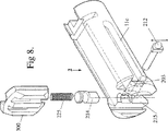
図7から図9に示したロックのさらに別の実施態様では、干渉手段を用いており、これは図5のリロッカーバーとは、2個のディスクではなく干渉要素を一つだけ用いているという点で異なっている。ここで、干渉要素はブロック212となっている。この実施態様の構成部品の形状やデザインは、図6Aの実施態様と異なっているが、機能は同じである。干渉手段がひとつだけ使用されているため、サイドバー溝11Cもサイドバー12Cも一つずつしか要らない。
【0056】
図8は、内側通路203や直立流路215を覆うための取り外し可能なカバー300の分解図である。ブロック212と支持体214の構成部品をプラグ内部に配した後は、カバー300でプラグの開口部をシールする。図9は、組立てた状態のリロッカーバーのさらなる実施態様である。
【0057】
実施態様を支える原理は、ロックの施錠メカニズムと相互作用できるような動きをもたらしうる、キーに含まれている、もしくはキーハンドルによって支持されている、メカニズムを提供することである。回転作動子が相互作用手段に横切る方向の動きを提供する実施態様について述べてきたが、当業者であれば当然、相互作用手段に同様の動きをもたらす他の回転作動子を想到できるであろう。したがって、本発明はその最も広い態様において、図2や図3Dに示された作動子片101の形状や構造に限定されない。
【0058】
また、好適な実施態様では、作動子片の平面がキーブレードの側壁と平行であったが、回転作動子の平面がキーブレードの面を横切る他の実施態様も可能である。
【0059】
図2のキーと図6Aや図7のロックとを組み合わせて形成したセキュリティシステムの実施態様においては、キーの回転作動子がロックの干渉手段と相互作用して、キーの相互作用手段のポジションが変化し、さらにロックの干渉手段のポジションも変化し、ロックの開錠を達成するようになった。
【0060】
本発明の実施態様によるキーに対応するロックの実施態様を2種類だけ述べたが、当業者にとっては当然、他のデザインがあることは明らかである。たとえば、作動子片のツノがタンブラーを押しつけて、プラグとシェルとの間を干渉しないように位置づけた別の実施態様がある。キーについても同様に他のデザインのものも可能である。たとえば、回転作動子をロックの面に押し付けるのではなく、キーのハンドルを絞ったり、回転させたり、あるいは押し付けたりして、可動要素に操作力をかけることもできる。本発明は、ブレードが1本だけのキーにおいても具現化可能である。このような場合、相互作用手段が単一のブレードの内側、もしくはそのブレードに横並びになっていてよい。さらに、可動要素が回転したり旋回したりするのでなく、滑動したり、あるいは曲線を描くトラックに沿って動いてもよい。図3Bおよび図3Cに示されているように、本発明のメカニズムの機能に影響を及ぼすことなく、キーハンドルの外観を変更してもよい。結局、前記請求範囲は広く解釈されるべきであり、上記で説明してきた好適な実施態様に限定すべきではない。
【図面の簡単な説明】
【図1】 従来技術のロックの分解図。
【図2】 キーがロックに挿入されていないときの作動部材の方向を示すキーの実施態様の断面図。
【図3A】 キーがロックに挿入されているときの作動部材の方向を示す図2のキーの断面図。
【図3B】 回転作動子を有するキーの実施態様の分解図。
【図3C】 図3Bのキーの組立状態の実施態様を示す図。
【図3D】 キーブレードが未だキーハンドルに着いていないときの回転作動子を有するキーハンドルの実施態様を示す図。
【図4A】 図2のキーによって操作可能なロック構成部品の実施態様を示す図。
【図4B】 内部構造をアウトラインで示した、図4Aのロック構成部品を示す図。
【図5】 図4Aおよび4Bのロック構成部品を施錠したり開錠したりするのに使う、リロッカーバーを示す図。
【図6A】 ロックのプラグ内部に配置された図5のリロッカーバーが付いて示された図4Aのロック構成部品付きのロックを示す図。
【図6B】 図6Aのロックの図6AのA−Aを通る平面についての断面図。
【図7】 図4Aから6Bの実施態様と、サイドバーと干渉要素とが一つずつしか備わっていないリロッカーを有する点で異なる、ロックの別の実施態様の分解図。
【図8】 図7のロックの別の構成部品の分解図。
【図9】図7のロックに使用されるリロッカーバーの実施態様の詳細図。[0001]
[Technical field to which the invention belongs]
The present invention relates to an improved key, key handle and locking device.
[0002]
[Prior art]
The sidebar lock in the prior art includes a cylindrical plug that is taken into an outer housing or shell for rotation in the shell. Furthermore, the shell is mounted in a suitable latch structure. The plug is then locked in the shell by interference between the shell and the plug. This locking condition occurs when the sidebar of the plug extends in a sidebar groove located along the side of the shell. This prevents the plug from rotating relative to the shell.
[0003]
The lock includes a sidebar pin that is oriented from the sidebar and protrudes into the plug. When the lock is in the locked state, the sidebar pins do not line up with the corresponding holes in the tumbler located in the plug. That is, the sidebar pin cannot be retracted into the sidebar slot through the entire length of the plug unless the correct key is inserted. When the correct key is inserted, the tumbler will rise in each degree and the tumbler holes will line up with the sidebar pins. As a result, the sidebar can fit into a slot in the side of the plug and no longer operates as impeding rotation of the plug within the shell. That is, the sidebar no longer operates as an obstruction to the rotation of the plug, so it can be said that the lock is in the unlocked state.
[0004]
Such a lock provides a high level of security, but it is desirable if the lock is more than adequately unlocked.
[0005]
An object of the present invention is to provide one of a high security key, a handle of such a key, and a corresponding lock operated by such a key.
[0006]
The key provided by the first invention of the present application has operation means and interaction means. rotation Including an actuator, the arrangement of these operating means and interaction means is operatively such that when the key is inserted into the lock, the operating means is forced and the position of the interaction means changes. It is.
[0007]
Preferably, the key is configured via an operation such that a force provided by a manual force applied by the user when inserting the key through the opening of the lock is applied to the operating means.
[0008]
The position change of the interaction means can be rotated with respect to the key body rotation Preferably achieved by an actuator.
[0009]
Alternatively, the position change of the interaction means can be pivoted with respect to the key body rotation It may be achieved by an actuator.
[0010]
The operating means is positioned so as to be pressed against the surface of the lock during lock insertion rotation It is preferable to include a part of the actuator.
[0011]
The interaction means is configured to interact with the lock during the locking or unlocking operation of the lock, and the position change of the interaction means is part of the locking or unlocking operation. Preferably there is.
[0012]
The interaction means are preferably arranged via operation so that they are positioned substantially inside the lock upon key insertion.
[0013]
The interaction means rotation It is preferable to include a protrusion from the actuator.
[0014]
A key blade is provided on the key, rotation Preferably, the actuator is positioned side by side with this blade.
[0015]
The key has at least two blades, rotation The actuators may be aligned along a plane between the two blades.
[0016]
Each blade is connected to the handle part of the key, rotation The operating means of the actuator may be substantially shielded by this handle portion, while the interaction means may be at least partially shielded by the blade portion.
[0017]
Preferably, each single blade or blades further includes teeth for the operation of the rock tumbler.
[0018]
When the key is not inserted in the lock, it is in the first position rotation It is preferable to further include an urging means for urging the operating element.
[0019]
In the first position, a part of the operating means protrudes beyond the surface of the key, and as a result, when the lock is inserted, the operating means is configured to be in contact with the lock surface. It is preferable.
[0020]
The key handle provided by the second invention has an operation means and an interaction means. rotation When a force is applied to the operating means including an actuator, the position of the interaction means changes, and this key handle is adapted to a key blade attached to the key handle, and the key that forms is an opening in the face of the lock Through operation to be inserted through.
[0021]
According to a third aspect of the present invention, there is provided a lock for operation by a key, wherein the key includes a movable element having an operation means and an interaction means, and the lock includes an interference means for unlocking corresponding to the interaction means.
[0022]
Preferably, the interference means comprises a closure element, which obstructs part of the lock and prevents the steps necessary for unlocking the lock from occurring.
[0023]
In one embodiment, the interference means includes a rocker bar supported by the anvil, and the anvil moves the rocker bar up and down in response to the interaction means, so that in the locked position, the rocker bar becomes an obstacle in the sidebar groove of the lock. On the other hand, the unlocker bar is prevented from entering the side bar groove at the unlocking position.
[0024]
The lock further includes a tumbler that moves the tumbler from its position that corresponds to the teeth located on the key blade and prevents the lock plug from rotating relative to the shell surrounding the plug. It is preferable that
[0025]
The security system provided by the fourth invention is:
a) a key including an operation means having an operation means and an interaction means, wherein the position of the interaction means changes when a force is applied to the operation means;
b) Lock for operation with the key. Plug Interference means for locking the surrounding lock shell is included, the interference means corresponding to the interaction means including the lock for unlocking the lock.
[0026]
The security system provided by the fifth invention is:
a) With the above keys
b) including the above-mentioned lock,
Key rotation The actuator interacts with the lock interference means, and the change in the position of the key interaction means causes the position change of the lock interference means to achieve unlocking of the lock.
[0027]
DETAILED DESCRIPTION OF THE INVENTION
In order that the invention may be more fully understood, embodiments of the invention will be described with reference to the accompanying drawings. However, it is not limited to these examples.
[0028]
In the following, a conventional embodiment will be described with respect to Bilock (registered trademark) as a prior art manufactured and sold by the present applicant. In these apparatuses, a key with two blades is used so that it can be applied to high security. Referring to FIG. 1, a prior
[0029]
When the
[0030]
FIG. 2 shows a cross-sectional view of an embodiment of the key 100. The key 100 includes a
[0031]
The key 100 is embodied as an
[0032]
rotation The actuator has operating means and interaction means. In this embodiment, the operating means is the
[0033]
rotation As a result of the movement of the actuator, the position of the interaction means changes. For example, in this embodiment, when the
[0034]
The
[0035]
The key is in the first position when not inserted in the lock rotation Biasing means for urging the actuator is included. FIG. 2 shows the operating piece in the first position. During the lock insertion, the biasing means as the
[0036]
In FIG. 3A, when the user pushes the key 100 into the lock and inserts it, the
[0037]
The purpose of the interaction means is to provide a movable element that can interact with the locking mechanism in some way. Since this movable element is provided on the key or key handle, it has become possible to design a lock in which this mechanism can be fully activated after the interaction means can be moved by the locking mechanism.
[0038]
The principle behind the design of the embodiment of FIGS. 2 and 3A is that the rotary or pivoting movement of the
[0039]
Furthermore, in this embodiment, the
[0040]
Since the interaction means is intended to interact with the locking mechanism, it is preferable that the interaction means be placed inside the lock when the key is inserted as an arrangement to be taken by the interaction means. In this embodiment, the interaction means formed as a
[0041]
In FIG. 2, the body of the
[0042]
In another embodiment, the interaction means is preferably supported by the key handle, and may be adapted to interact with an external mechanism arranged outside the lock surface. In such an embodiment, the interaction means, such as the
[0043]
In the embodiment of FIGS. 2 to 3C, the key is provided with two or more blades. rotation The plane of the actuator is preferably laid on one of the blades and aligned along the plane between the two blades and / or between the two walls of the
[0044]
FIG. 3D shows another embodiment of the present invention that results in a
[0045]
An embodiment of the lock that can be interacted by the interaction means in the embodiment of the key or the key handle as described above will be described below.
[0046]
FIG. 4A shows an embodiment of a lock that includes a mechanism that is locked and / or unlocked as a result of interaction with the interaction means in the embodiment of a key or key handle of the type described above. Show.
[0047]
In contrast to the prior art lock of FIG. 1, the embodiment of FIG. 4A is compared. (Similar parts are represented by similar numbers in both the prior art and embodiments for ease of understanding of this embodiment only). In contrast to the prior art of FIG. 1, the lock of FIG. 4A is provided with a passage 203 (best shown in FIG. 6B). This
[0048]
In FIG. 4A, the locking plug 2 is provided with interference means, which includes two
[0049]
In FIG. 4A, when the
[0050]
The transverse movement of the
[0051]
In FIG. 6A, a
[0052]
In the locked position as shown in FIGS. 6A and 6B, the
[0053]
In order to rotate the plug 2 through the
[0054]
The upward movement of the
[0055]
Still another embodiment of the lock shown in FIGS. 7-9 uses interference means, which means that the locker bar of FIG. 5 uses only one interference element rather than two disks. It is different in point. Here, the interference element is a
[0056]
FIG. 8 is an exploded view of the
[0057]
The principle supporting the embodiment is to provide a mechanism that is included in the key or supported by the key handle that can provide movement that can interact with the locking mechanism of the lock. rotation While embodiments have been described in which the actuator provides movement in a direction across the interaction means, those skilled in the art will naturally recognize other movements that provide similar movement to the interaction means. rotation An actuator could be conceived. Therefore, the present invention is not limited to the shape and structure of the
[0058]
In a preferred embodiment, the plane of the actuator piece is parallel to the side wall of the key blade. rotation Other embodiments are possible where the plane of the actuator crosses the face of the key blade.
[0059]
In the embodiment of the security system formed by combining the key of FIG. 2 and the lock of FIG. 6A or FIG. rotation When the actuator interacts with the lock interference means, the position of the key interaction means changes, and the position of the lock interference means also changes, thereby achieving unlocking of the lock.
[0060]
Although only two types of lock embodiments corresponding to keys according to embodiments of the present invention have been described, it will be apparent to those skilled in the art that there are other designs. For example, there is another embodiment in which the horn of the actuator piece presses the tumbler and is positioned so as not to interfere between the plug and the shell. Other designs for the key are possible as well. For example, rotation Instead of pressing the actuator against the surface of the lock, it is possible to apply an operating force to the movable element by squeezing, rotating, or pressing the key handle. The present invention can also be embodied in a key having only one blade. In such a case, the interaction means may be inside a single blade or beside it. In addition, the movable element may slide or move along a curved track rather than rotating or turning. As shown in FIGS. 3B and 3C, the appearance of the key handle may be changed without affecting the function of the mechanism of the present invention. In the end, the claims are to be interpreted broadly and should not be limited to the preferred embodiments described above.
[Brief description of the drawings]
FIG. 1 is an exploded view of a prior art lock.
FIG. 2 is a cross-sectional view of an embodiment of the key showing the orientation of the actuating member when the key is not inserted into the lock.
3A is a cross-sectional view of the key of FIG. 2 showing the direction of the actuating member when the key is inserted into the lock.
FIG. 3B rotation FIG. 3 is an exploded view of an embodiment of a key having an actuator.
3C shows an embodiment of the assembled state of the key of FIG. 3B.
FIG. 3D: When the key blade is not yet attached to the key handle rotation The figure which shows the embodiment of the key handle which has an actuator.
4A shows an embodiment of a locking component operable by the key of FIG.
4B shows the locking component of FIG. 4A with the internal structure shown in outline.
FIG. 5 shows a locker bar used to lock and unlock the locking components of FIGS. 4A and 4B.
6A shows the lock with the locking component of FIG. 4A shown with the locker bar of FIG. 5 placed inside the plug of the lock.
6B is a cross-sectional view of the lock of FIG. 6A with respect to the plane through AA of FIG. 6A.
7 is an exploded view of another embodiment of a lock that differs from the embodiment of FIGS. 4A-6B in that it has a locker with only one sidebar and one interference element. FIG.
8 is an exploded view of another component of the lock of FIG.
9 is a detailed view of an embodiment of a rocker bar used in the lock of FIG.
Claims (20)
少なくとも1つのキーブレードに対して可動の少なくとも1つの回転作動子とを有し、
回転作動子は、一体形成された操作手段と相互作用手段とを有し、
回転作動子は、キーブレードの面に直交する回転軸線を有し、少なくとも1つのキーブレードに並置され、
操作手段は、ロック挿入中ロックの面に押し付けられるように配置された回転作動子の一部であり、
キーがロック内に挿入されたとき、ロックの面によって操作手段に加えられる力が回転作動子を回転させ、相互作用手段の位置がキーブレードに対して変化し、
相互作用手段の位置の変化がロックの施錠および開錠作用の少なくとも一方の補助部であり、
少なくとも1つのキーブレードがロック内に挿入されていないとき、回転作動子の操作手段を押し下げるとともに当該操作手段と反対側の端部を押し上げるように付勢するための付勢手段が設けられることを特徴とするキー。At least one key blade;
At least one rotary actuator movable with respect to at least one key blade;
The rotary actuator has operation means and interaction means formed integrally,
The rotary actuator has a rotation axis perpendicular to the surface of the key blade and is juxtaposed with at least one key blade;
The operating means is part of a rotary actuator arranged to be pressed against the surface of the lock during lock insertion,
When the key is inserted into the lock, the force applied to the operating means by the surface of the lock rotates the rotary actuator, the position of the interaction means changes relative to the key blade,
The change in the position of the interaction means is at least one auxiliary part of locking and unlocking action of the lock,
When at least one key blade is not inserted in the lock, an urging means is provided for urging to push down the operating means of the rotary actuator and push up the end opposite to the operating means. Key to feature.
回転作動子は、キーブレードの面に直交する回転軸線を有し、少なくとも1つのキーブレードに並置され、
操作手段は、キーをロックに挿入する間、ロックの面に押し付けられるように配置された回転作動子の一部であり、
キーブレードの少なくとも1つがロック内に挿入されたとき、ロックの面によって操作手段に加えられる力が回転作動子を回転させ、相互作用手段の位置が変化され、
相互作用手段の位置変化が、ロックの施錠および開錠の少なくとも一方の補助部であり、
操作手段に力が加えられていないとき、操作手段を押し下げるとともに当該操作手段と反対側の端部を押し上げるように回転作動子を付勢するための付勢手段が設けられることを特徴とするキーハンドル。At least one rotary actuator movable with respect to at least one key blade, the rotary actuator having operating means and interaction means formed integrally; Forming,
The rotary actuator has a rotation axis perpendicular to the surface of the key blade and is juxtaposed with at least one key blade;
The operating means is a part of a rotary actuator arranged to be pressed against the surface of the lock while inserting the key into the lock,
When at least one of the key blades is inserted into the lock, the force applied to the operating means by the face of the lock rotates the rotary actuator, changing the position of the interaction means,
The change in the position of the interaction means is at least one auxiliary part for locking and unlocking the lock,
A key characterized in that, when no force is applied to the operating means, a biasing means is provided for biasing the rotary actuator so as to push down the operating means and push up the end opposite to the operating means. handle.
キーブレードと係合し、ロックの施錠および開錠の少なくとも一方の部分を提供する複数のタンブラと、
キーに配置された回転作動子の相互作用手段に応答し、キーブレードに対して可動で、ロックの施錠および開錠の少なくとも一方の補助部を提供する少なくとも1つの干渉手段とを有し、
回転作動子は、キーブレードの面に直交する回転軸線を有し、キーブレードに並置され、
回転作動子は、一体に形成された操作手段を有し、操作手段は、ロックに挿入している間、ロックの面に押し付けられるように配置され、
キーがロック内に挿入されたとき、ロックの面によって操作手段に加えられる力が回転作動子を回転させ、少なくとも1つの干渉手段と係合するために、相互作用手段の位置がキーブレードに対して変化し、
少なくとも1つのキーブレードがロック内に挿入されていないとき、前記回転作動子の操作手段を押し下げるとともに当該操作手段と反対側の端部を押し上げるように付勢するための付勢手段が設けられることを特徴とするロック。In lock operated by key,
A plurality of tumblers that engage the key blade and provide at least one part of locking and unlocking of the lock;
Responsive to interaction means of a rotary actuator disposed on the key, having at least one interference means movable relative to the key blade and providing at least one auxiliary part of locking and unlocking of the lock;
The rotary actuator has a rotation axis perpendicular to the surface of the key blade, juxtaposed to the key blade,
The rotary actuator has operation means formed integrally, and the operation means is arranged to be pressed against the surface of the lock while being inserted into the lock,
When the key is inserted into the lock, the force applied to the operating means by the surface of the lock causes the rotary actuator to rotate and engage with at least one interference means so that the position of the interaction means relative to the key blade Change,
When at least one key blade is not inserted in the lock, an urging means is provided for urging to push down the operation means of the rotary actuator and push up the end opposite to the operation means. Lock characterized by.
キーによって作動するロックとを有し、
少なくとも1つの回転作動子は、一体形成された操作手段と相互作用手段とを有し、
少なくとも1つの回転作動子は、キーブレードの面に直交する回転軸線を有し、少なくとも1つのキーブレードに並置され、
操作手段は、ロックに挿入されている間、ロックの面に押し付けられるように配置された少なくとも1つの回転作動子の一部であり、
回転作動子は、操作手段に加えられる力により回転し、相互作用手段の位置がキーブレードに対して変化し、
ロックは、ロックのプラグを取り囲むロックシェルにロックするための干渉手段を有し、干渉手段は、ロックの施錠および開錠の少なくとも一方の補助部として相互作用手段に応答し、
少なくとも1つのキーブレードがロック内に挿入されていないとき、回転作動子の操作手段を押し下げるとともに当該操作手段と反対側の端部を押し上げるように付勢するための付勢手段が設けられることを特徴とするセキュリティシステム。A key having at least one key blade and at least one rotary actuator movable relative to the at least one key blade;
A lock activated by a key,
At least one rotary actuator has integrally formed operating means and interaction means,
At least one rotary actuator having a rotational axis perpendicular to the plane of the key blade and juxtaposed with the at least one key blade;
The operating means is part of at least one rotary actuator arranged to be pressed against the surface of the lock while being inserted into the lock;
The rotary actuator is rotated by the force applied to the operation means, the position of the interaction means is changed with respect to the key blade,
The lock has an interference means for locking to a lock shell surrounding the plug of the lock, the interference means being responsive to the interaction means as an aid for at least one of locking and unlocking the lock;
When at least one key blade is not inserted in the lock, an urging means is provided for urging to push down the operating means of the rotary actuator and push up the end opposite to the operating means. A featured security system.
Applications Claiming Priority (3)
| Application Number | Priority Date | Filing Date | Title |
|---|---|---|---|
| AU5724 | 1998-09-04 | ||
| AUPP5724A AUPP572498A0 (en) | 1998-09-04 | 1998-09-04 | Moveable element lock and key |
| PCT/AU1999/000722 WO2000014366A1 (en) | 1998-09-04 | 1999-09-03 | Moveable element key and key handle and lock |
Publications (3)
| Publication Number | Publication Date |
|---|---|
| JP2002524676A JP2002524676A (en) | 2002-08-06 |
| JP2002524676A5 JP2002524676A5 (en) | 2006-10-12 |
| JP4540849B2 true JP4540849B2 (en) | 2010-09-08 |
Family
ID=3809948
Family Applications (1)
| Application Number | Title | Priority Date | Filing Date |
|---|---|---|---|
| JP2000569089A Expired - Fee Related JP4540849B2 (en) | 1998-09-04 | 1999-09-03 | Movable element key and key handle and locking device |
Country Status (11)
| Country | Link |
|---|---|
| US (1) | US6681609B1 (en) |
| EP (1) | EP1112428B1 (en) |
| JP (1) | JP4540849B2 (en) |
| CN (1) | CN1278006C (en) |
| AT (1) | ATE331863T1 (en) |
| AU (1) | AUPP572498A0 (en) |
| DE (1) | DE69932168T2 (en) |
| HK (1) | HK1041037B (en) |
| ID (1) | ID27973A (en) |
| NZ (1) | NZ510598A (en) |
| WO (1) | WO2000014366A1 (en) |
Families Citing this family (16)
| Publication number | Priority date | Publication date | Assignee | Title |
|---|---|---|---|---|
| CN1668519A (en) | 2002-06-04 | 2005-09-14 | 兰普森创意股份有限公司 | Security system |
| PL207157B1 (en) * | 2002-07-24 | 2010-11-30 | Ernst Keller | Security key and locking cylinder |
| GB2412689B (en) * | 2004-03-30 | 2006-10-04 | Mul T Lock Technologies Ltd | Key combination element in key blank and key |
| US20060230797A1 (en) * | 2004-12-14 | 2006-10-19 | Robert Strong | Key core |
| WO2008156664A2 (en) | 2007-06-13 | 2008-12-24 | Schlage Lock Company | Programmable lock cylinder assembly |
| US8621902B2 (en) * | 2007-06-13 | 2014-01-07 | Schlage Lock Company Llc | Master keying system and method for programmable lock cylinder assemblies |
| US8490446B2 (en) | 2010-04-23 | 2013-07-23 | Schlage Lock Company | Programmable lock cylinder assembly |
| DE102010049174B3 (en) * | 2010-07-16 | 2012-01-26 | ABUS August Bremicker Söhne KG | Lock and key system |
| WO2013169760A1 (en) | 2012-05-08 | 2013-11-14 | Schlage Lock Company Llc | Variable section key and lock |
| CN104033018A (en) * | 2013-03-06 | 2014-09-10 | 钟新朔 | Theft-proof lock cylinder |
| US9359793B2 (en) * | 2013-10-03 | 2016-06-07 | Medeco Security Locks, Inc. | Cylinder lock with internal slider and key therefore |
| AU2013248267B1 (en) * | 2013-10-28 | 2014-06-26 | Camware Holdings Pty Ltd | Lock system |
| CN105133936A (en) * | 2015-09-23 | 2015-12-09 | 万沙电气有限公司 | One-way self-buckling type rotating wheel sliding lock bar |
| CN107476664B (en) * | 2017-09-20 | 2023-04-07 | 邯郸市亮佳门业有限公司 | Anti-theft lock |
| JP3221283U (en) * | 2019-02-26 | 2019-05-16 | オムロン株式会社 | Key accessories |
| NZ787766A (en) | 2019-10-03 | 2024-03-22 | Assa Abloy High Security Group Inc | Key blank with movable element, corresponding key and corresponding lock plug and lock assembly |
Family Cites Families (48)
| Publication number | Priority date | Publication date | Assignee | Title |
|---|---|---|---|---|
| US485899A (en) * | 1892-11-08 | tannenberg | ||
| US130609A (en) * | 1872-08-20 | Improvement in door-locks | ||
| US167168A (en) * | 1875-08-31 | Improvement in keys for locks | ||
| US188827A (en) * | 1877-03-27 | Improvement in keys for locks | ||
| US827201A (en) * | 1905-05-05 | 1906-07-31 | Isaac Ash | Key. |
| US888478A (en) * | 1906-08-27 | 1908-05-26 | Samuel Drew | Lock. |
| US947913A (en) * | 1909-04-14 | 1910-02-01 | Charles Francis Jenkins | Key and lock. |
| US1070757A (en) * | 1913-01-29 | 1913-08-19 | Fred W Kellar | Lock. |
| US1105093A (en) * | 1913-06-09 | 1914-07-28 | Albert M Keane | Lock. |
| US1356747A (en) * | 1919-11-06 | 1920-10-26 | Skolneek Christ | Lock |
| US1567979A (en) * | 1924-01-26 | 1925-12-29 | Clara L Northrop | Lock |
| US1735868A (en) * | 1926-04-14 | 1929-11-19 | Robert H Klingel | Key-operated lock |
| US1750542A (en) * | 1926-07-08 | 1930-03-11 | Frank Diblick | Lock and key structure |
| DE633936C (en) * | 1934-11-09 | 1936-08-11 | Alfred Kurdewan | Key for insert locks |
| US2620694A (en) | 1945-04-12 | 1952-12-09 | Jansson Janne Walfrid | Quick-action type vise having pawllocked slidable jaw |
| DE1093253B (en) | 1958-03-20 | 1960-11-17 | Dr Wilhelm Geller | Key for rotary cylinder lock |
| DE1242464B (en) | 1964-07-30 | 1967-06-15 | Voss Kg J | Steering wheel lock for motor vehicles equipped with ignition switch |
| US3486355A (en) | 1968-02-21 | 1969-12-30 | Oliver C Halfyard | Safety key and lock |
| US3754422A (en) | 1972-06-26 | 1973-08-28 | American Locker Co | Cylinder lock and u-shaped key and method of forming same |
| US3968668A (en) | 1973-08-15 | 1976-07-13 | Norman Lock Co. | Pickproof cylinder lock |
| FR2318294A1 (en) | 1975-07-18 | 1977-02-11 | Fredon Pierre | LOCKING DEVICES IMPROVEMENTS |
| US4040279A (en) | 1976-10-04 | 1977-08-09 | Signorelli John A | Security lock and key |
| US4155232A (en) | 1978-01-24 | 1979-05-22 | Haus Paul Z Jr | Multi-combination security lock and key |
| US4404824A (en) * | 1981-02-05 | 1983-09-20 | Lori Corporation | Side-bar lock |
| US4478061A (en) * | 1981-03-30 | 1984-10-23 | Taboola Pty. Limited | Cylinder lock |
| NZ205985A (en) | 1982-10-27 | 1986-10-08 | Ogden Industries Pty Ltd | Plate tumbler lock with locking pin |
| NZ206292A (en) | 1982-11-23 | 1986-07-11 | M E F Strassmeir | Cylinder lock assembly:individual locking pins arranged in one or more rows engage adjacent row of tumbler pins transverse to longitudinal axis of tumbler pins |
| AT385077B (en) | 1983-06-30 | 1988-02-10 | Grundmann Gmbh Geb | KEY-LOCK COMBINATION ON A CYLINDLE LOCK BASE |
| FR2561294B1 (en) | 1984-03-14 | 1986-10-03 | Vachette Sa | MOBILE PUSH-BUTTON, SECURITY BARREL FOR SAID KEY, AND LOCK EQUIPPED WITH SUCH A BARREL |
| IT1208841B (en) * | 1985-12-19 | 1989-07-10 | Rielda Serrature Srl | CYLINDER LOCK WITH INTERCHANGEABLE KEY |
| JPH0344932Y2 (en) * | 1986-05-08 | 1991-09-20 | ||
| FR2604206B1 (en) * | 1986-09-24 | 1988-12-30 | Profalux | LOCK KEY AND APPARATUS THEREFOR. |
| US4840049A (en) | 1986-09-26 | 1989-06-20 | Gas Energy, Inc. | Plunger lock and key |
| US4747282A (en) * | 1987-04-03 | 1988-05-31 | Nyun Albert S | Guard device for automobile ignition lock |
| ES2007674A6 (en) * | 1987-07-30 | 1989-07-01 | Widen Innovation Ab | Key blade for cylinder lock |
| FR2619149B1 (en) | 1987-08-05 | 1993-09-03 | Vachette Sa | TRANSLATABLE PUSH BUTTON, SAFETY BARREL FOR SUCH A KEY, AND LOCK EQUIPPED WITH SUCH A BARREL |
| GB8722917D0 (en) | 1987-09-30 | 1987-11-04 | Piper M J | Keys |
| IT1235586B (en) * | 1989-09-06 | 1992-09-11 | Italiana Serrature Affini | CYLINDER LOCK AND RELATED KEY |
| US5076081A (en) | 1990-07-06 | 1991-12-31 | Lori Corporation | Key for interchangable core lock |
| US5224365A (en) * | 1992-08-10 | 1993-07-06 | Dobbs Jerry L | Side bar lock decoder |
| IL104349A (en) | 1993-01-08 | 1997-01-10 | Mul T Lock Ltd | Locking apparatus |
| FR2704893B1 (en) | 1993-05-05 | 1995-08-11 | Tesa | Safety lock and open key for such a lock. |
| US5355702A (en) * | 1993-10-04 | 1994-10-18 | Augusto Escribens | Security combination key |
| IT1268685B1 (en) | 1994-12-27 | 1997-03-06 | Silca Spa | KEY UNIT AND CYLINDER LOCK |
| ES2128898B1 (en) * | 1995-08-02 | 1999-12-16 | Talleres Escoriaza Sa | IRREPRODUCIBLE KEY SYSTEM OF LOCK AND CYLINDER FOR SUCH KEY. |
| US5956986A (en) * | 1995-12-11 | 1999-09-28 | R. Berchtold A.G. | Locking device with a cylinder lock and a flat key |
| US5706683A (en) * | 1996-05-14 | 1998-01-13 | Napier; Robert M. | Key mechanism |
| IT1291177B1 (en) * | 1997-03-10 | 1998-12-29 | Rielda Srl | PROGRAMMABLE CYLINDER LOCK, PROVIDED WITH MASTER KEYS. |
-
1998
- 1998-09-04 AU AUPP5724A patent/AUPP572498A0/en not_active Abandoned
-
1999
- 1999-09-03 ID IDW20010756A patent/ID27973A/en unknown
- 1999-09-03 CN CNB998117862A patent/CN1278006C/en not_active Expired - Fee Related
- 1999-09-03 JP JP2000569089A patent/JP4540849B2/en not_active Expired - Fee Related
- 1999-09-03 NZ NZ510598A patent/NZ510598A/en not_active IP Right Cessation
- 1999-09-03 EP EP99945756A patent/EP1112428B1/en not_active Expired - Lifetime
- 1999-09-03 AT AT99945756T patent/ATE331863T1/en not_active IP Right Cessation
- 1999-09-03 WO PCT/AU1999/000722 patent/WO2000014366A1/en active IP Right Grant
- 1999-09-03 US US09/786,489 patent/US6681609B1/en not_active Expired - Lifetime
- 1999-09-03 DE DE69932168T patent/DE69932168T2/en not_active Expired - Lifetime
-
2002
- 2002-04-04 HK HK02102490.9A patent/HK1041037B/en not_active IP Right Cessation
Also Published As
| Publication number | Publication date |
|---|---|
| CN1278006C (en) | 2006-10-04 |
| ATE331863T1 (en) | 2006-07-15 |
| NZ510598A (en) | 2003-02-28 |
| EP1112428B1 (en) | 2006-06-28 |
| DE69932168T2 (en) | 2007-05-31 |
| JP2002524676A (en) | 2002-08-06 |
| EP1112428A1 (en) | 2001-07-04 |
| AUPP572498A0 (en) | 1998-10-01 |
| US6681609B1 (en) | 2004-01-27 |
| HK1041037A1 (en) | 2002-06-28 |
| WO2000014366A1 (en) | 2000-03-16 |
| HK1041037B (en) | 2006-12-22 |
| CN1322269A (en) | 2001-11-14 |
| ID27973A (en) | 2001-05-03 |
| EP1112428A4 (en) | 2001-12-19 |
| DE69932168D1 (en) | 2006-08-10 |
Similar Documents
| Publication | Publication Date | Title |
|---|---|---|
| JP4540849B2 (en) | Movable element key and key handle and locking device | |
| US7213425B2 (en) | Padlock having dual unlocking modes | |
| US7458239B1 (en) | Combination-changeable complex lock | |
| JP2011007035A (en) | Disk tumbler cylinder type cylinder lock | |
| KR960011949B1 (en) | Mechanical lock and key | |
| US6553796B2 (en) | Electrical panel lock with locking plug head | |
| AU753733C (en) | Moveable element key and key handle and lock | |
| AU2005202446B2 (en) | Moveable element key and key handle and lock | |
| AU713159B3 (en) | Moveable element key and lock system | |
| AU782779B2 (en) | Moveable element key and key handle and lock | |
| JP3348072B2 (en) | Lock device | |
| JP4128375B2 (en) | Locking and unlocking device | |
| JP4113714B2 (en) | Rotary disc tumbler lock | |
| JPH102134A (en) | Cylinder lock | |
| JP4138431B2 (en) | Mounting structure for rear-facing crime prevention thumb turn for sliding door | |
| JPS5829229Y2 (en) | lock case handle | |
| JP3926660B2 (en) | Cylinder used for cylinder lock and cylinder lock provided with the same | |
| JP2001303813A (en) | Cylinder lock and its key | |
| JP4478528B2 (en) | Case locking device | |
| JP3378218B2 (en) | Door lock devices for vending machines, etc. | |
| JP3416362B2 (en) | Variable code type cylinder lock | |
| JP2000087604A (en) | Cylinder lock | |
| JPH0529322Y2 (en) | ||
| JP4478619B2 (en) | Thumb turn unit | |
| CA1065638A (en) | High security deadbolt lock |
Legal Events
| Date | Code | Title | Description |
|---|---|---|---|
| A521 | Request for written amendment filed |
Free format text: JAPANESE INTERMEDIATE CODE: A523 Effective date: 20060822 |
|
| A621 | Written request for application examination |
Free format text: JAPANESE INTERMEDIATE CODE: A621 Effective date: 20060822 |
|
| A131 | Notification of reasons for refusal |
Free format text: JAPANESE INTERMEDIATE CODE: A131 Effective date: 20090804 |
|
| A601 | Written request for extension of time |
Free format text: JAPANESE INTERMEDIATE CODE: A601 Effective date: 20091104 |
|
| A521 | Request for written amendment filed |
Free format text: JAPANESE INTERMEDIATE CODE: A523 Effective date: 20091106 |
|
| A602 | Written permission of extension of time |
Free format text: JAPANESE INTERMEDIATE CODE: A602 Effective date: 20091111 |
|
| A131 | Notification of reasons for refusal |
Free format text: JAPANESE INTERMEDIATE CODE: A131 Effective date: 20100119 |
|
| A521 | Request for written amendment filed |
Free format text: JAPANESE INTERMEDIATE CODE: A523 Effective date: 20100330 |
|
| TRDD | Decision of grant or rejection written | ||
| A01 | Written decision to grant a patent or to grant a registration (utility model) |
Free format text: JAPANESE INTERMEDIATE CODE: A01 Effective date: 20100525 |
|
| A01 | Written decision to grant a patent or to grant a registration (utility model) |
Free format text: JAPANESE INTERMEDIATE CODE: A01 |
|
| A61 | First payment of annual fees (during grant procedure) |
Free format text: JAPANESE INTERMEDIATE CODE: A61 Effective date: 20100623 |
|
| R150 | Certificate of patent or registration of utility model |
Free format text: JAPANESE INTERMEDIATE CODE: R150 |
|
| FPAY | Renewal fee payment (event date is renewal date of database) |
Free format text: PAYMENT UNTIL: 20130702 Year of fee payment: 3 |
|
| FPAY | Renewal fee payment (event date is renewal date of database) |
Free format text: PAYMENT UNTIL: 20130702 Year of fee payment: 3 |
|
| FPAY | Renewal fee payment (event date is renewal date of database) |
Free format text: PAYMENT UNTIL: 20140702 Year of fee payment: 4 |
|
| LAPS | Cancellation because of no payment of annual fees |