JP4537102B2 - How to assemble a copy - Google Patents
How to assemble a copy Download PDFInfo
- Publication number
- JP4537102B2 JP4537102B2 JP2004098657A JP2004098657A JP4537102B2 JP 4537102 B2 JP4537102 B2 JP 4537102B2 JP 2004098657 A JP2004098657 A JP 2004098657A JP 2004098657 A JP2004098657 A JP 2004098657A JP 4537102 B2 JP4537102 B2 JP 4537102B2
- Authority
- JP
- Japan
- Prior art keywords
- shuttle
- zone
- fixed
- fixing zone
- fixing
- Prior art date
- Legal status (The legal status is an assumption and is not a legal conclusion. Google has not performed a legal analysis and makes no representation as to the accuracy of the status listed.)
- Expired - Lifetime
Links
- 238000000034 method Methods 0.000 claims description 55
- 230000003014 reinforcing effect Effects 0.000 claims description 53
- 230000002787 reinforcement Effects 0.000 claims description 17
- 238000009434 installation Methods 0.000 claims description 12
- 230000002093 peripheral effect Effects 0.000 claims description 5
- 238000000926 separation method Methods 0.000 claims description 3
- 230000008878 coupling Effects 0.000 claims 2
- 238000010168 coupling process Methods 0.000 claims 2
- 238000005859 coupling reaction Methods 0.000 claims 2
- 230000000875 corresponding effect Effects 0.000 description 11
- 229910000831 Steel Inorganic materials 0.000 description 8
- 239000010959 steel Substances 0.000 description 8
- 238000011144 upstream manufacturing Methods 0.000 description 7
- 238000010586 diagram Methods 0.000 description 3
- 239000000725 suspension Substances 0.000 description 3
- 238000013459 approach Methods 0.000 description 2
- 238000001514 detection method Methods 0.000 description 2
- 238000003780 insertion Methods 0.000 description 2
- 230000037431 insertion Effects 0.000 description 2
- 230000002411 adverse Effects 0.000 description 1
- 230000002079 cooperative effect Effects 0.000 description 1
- 230000000694 effects Effects 0.000 description 1
- 239000002184 metal Substances 0.000 description 1
Images


Classifications
-
- E—FIXED CONSTRUCTIONS
- E01—CONSTRUCTION OF ROADS, RAILWAYS, OR BRIDGES
- E01D—CONSTRUCTION OF BRIDGES, ELEVATED ROADWAYS OR VIADUCTS; ASSEMBLY OF BRIDGES
- E01D21/00—Methods or apparatus specially adapted for erecting or assembling bridges
-
- E—FIXED CONSTRUCTIONS
- E01—CONSTRUCTION OF ROADS, RAILWAYS, OR BRIDGES
- E01D—CONSTRUCTION OF BRIDGES, ELEVATED ROADWAYS OR VIADUCTS; ASSEMBLY OF BRIDGES
- E01D19/00—Structural or constructional details of bridges
- E01D19/16—Suspension cables; Cable clamps for suspension cables ; Pre- or post-stressed cables
-
- E—FIXED CONSTRUCTIONS
- E01—CONSTRUCTION OF ROADS, RAILWAYS, OR BRIDGES
- E01D—CONSTRUCTION OF BRIDGES, ELEVATED ROADWAYS OR VIADUCTS; ASSEMBLY OF BRIDGES
- E01D11/00—Suspension or cable-stayed bridges
-
- E—FIXED CONSTRUCTIONS
- E04—BUILDING
- E04G—SCAFFOLDING; FORMS; SHUTTERING; BUILDING IMPLEMENTS OR AIDS, OR THEIR USE; HANDLING BUILDING MATERIALS ON THE SITE; REPAIRING, BREAKING-UP OR OTHER WORK ON EXISTING BUILDINGS
- E04G21/00—Preparing, conveying, or working-up building materials or building elements in situ; Other devices or measures for constructional work
- E04G21/12—Mounting of reinforcing inserts; Prestressing
Landscapes
- Engineering & Computer Science (AREA)
- Architecture (AREA)
- Civil Engineering (AREA)
- Structural Engineering (AREA)
- Mechanical Engineering (AREA)
- Bridges Or Land Bridges (AREA)
- Lift-Guide Devices, And Elevator Ropes And Cables (AREA)
- Conveying And Assembling Of Building Elements In Situ (AREA)
Description
本発明は、土木工事の構造物の懸架機構に付属する控えを組み立てるために、ストランドのような張力をかけられた補強部材を外被内に設置することに関する。 The present invention relates to the installation of a tensioned reinforcing member, such as a strand, in a jacket for assembling a retainer attached to a suspension mechanism for a civil engineering structure.
控え式の懸架では、1つまたは2つ以上の鉄塔が、例えば橋のデッキのような構造物を、鉄塔と構造物の間の斜めの経路に沿った一組の控えによって支持している。控えは、2つの端部固定部間で張力をかけられ、一般的に外被によって囲まれた一組の補強部材から構成されている。これらの補強部材は金属製のストランドであることが多い。控え式の橋に関するかぎり、各補強部材は、それが支持に関与する橋の鉄塔とデッキに固定されている。 In a standstill suspension, one or more towers support a structure, such as a bridge deck, for example, with a set of stays along an oblique path between the tower and the structure. The stay is composed of a set of reinforcing members that are tensioned between two end fixtures and are generally surrounded by a jacket. These reinforcing members are often metal strands. As far as a stand-alone bridge is concerned, each reinforcement member is secured to the tower and deck of the bridge it is involved in supporting.
有利なことに、様々なストランド間で張力を均衡させ、同時に、集合的なジャッキよりもずっと軽量で(特に鉄塔上で)操作しやすい、単一ストランド式のジャッキを使用するのを可能にする、控えの複数のストランドに張力をかける方法が特許文献1に記載されている。この方法によれば、第1のストランドが、基準ストランドを構成するために張力をかけられる。その後の各ストランドは、その張力が基準ストランドの張力と同じ値になるまで単一ストランドジャッキによって張力をかけられる。この操作の間、既に固定されている各ストランドの張力が、新たなストランドの張力が強くなるのと同時にいくらか弱くなる。この操作方法によって、控えの様々なストランドにかけられる張力が次第に同じ値になるのが保障される。
大形の構造物の場合、用いられる控えは通常、数百メートルに及ぶこともある長大な長さを有し、荷重を支持するために、張力をかけられた多数の基本補強部材(ストランドなど)を設けなければならない。 In the case of large structures, the storage used typically has a long length, which may be several hundred meters, and a number of basic reinforcement members (strands etc.) that are tensioned to support the load. ) Must be provided.
さらに、(500mを超える)非常に広いスパンを有する、控え式の構造物上では、複数の控えの面上の空気抵抗力が、デッキに対する風の作用にとって支配的であり、鉄塔の大きさが過大になることにつながる場合がある。空気抵抗力は外被の直径に比例するので、直径の小さい外被を有する控え、すなわち、よりコンパクトな控えを設けるのが望ましい。 In addition, on constrained structures with very wide spans (greater than 500 m), the air resistance on the surfaces of the multiple constrains dominates the wind action on the deck, and the size of the tower is It may lead to overload. Since the air resistance is proportional to the diameter of the jacket, it is desirable to provide a storage with a smaller diameter jacket, i.e. a more compact storage.
したがって、控えの支持能力を高めるために最大限にするのが望ましい、ストランドの、控え当たりの本数と、空気力学的な理由から最小限に抑えるのが望ましい、控えの直径の、困難な折り合いを図らなければならない。 Therefore, it is desirable to maximize the number of strands, the number per strand, which is desirable to increase the bearing capacity of the staples, and the difficult diameter of the staples, which should be minimized for aerodynamic reasons. Must be planned.
一般に、控えの設置時に補強部材を通すために外被内に空間を設ける必要がある。厳密に言えば、大きい橋の控えは非常に重く、したがって、控えをデッキ上で、または事前組立てゾーン上で事前に組み立てた後に控えを引き上げることは考えられない。一般に、外被が、控えの、斜めの経路に沿った所定の位置に配置され、その後、複数のストランドが、外被内を滑る、鉄塔上に位置するウィンチによって駆動されるシャトルによって引き上げることによって、1つずつまたは小さな群ごとに設置される。最後のストランド(または最後の群)を引き上げる間、シャトルが通過できるように外被内に十分な空間が残っていなければならない。上記の折り合いを図る観点から、この残留空間を最小限に抑えるのが明らかに望ましい。 In general, it is necessary to provide a space in the outer jacket in order to allow the reinforcing member to pass through during installation of the storage. Strictly speaking, the large bridge reserves are very heavy and therefore it is not conceivable to lift the reserves after they have been pre-assembled on the deck or on the pre-assembly zone. Generally, the jacket is placed in place along a conservative, oblique path, after which the multiple strands are pulled up by a shuttle driven by a winch located on a steel tower that slides within the jacket. One by one or small group. While pulling up the last strand (or last group), there must be enough space in the jacket to allow the shuttle to pass through. From the standpoint of achieving the above compromise, it is clearly desirable to minimize this residual space.
特許文献2では、外被が、ストランドの束に張力をかけた後でこの束の周りに組み立てられた複数のシェルから成り、したがって、最小限の空間のみを残すのが可能であることによって、この問題は回避されている。しかし、控えの一般的な構成では、外被を複数の部品としてではなく1つの部材として設けるのが明らかに好ましい。この場合、特に、環境による悪影響に対する補強部材の良好な保護が得られる。 In U.S. Patent No. 6,057,049, the outer jacket consists of a plurality of shells assembled around the bundle of strands after being tensioned, thus allowing only minimal space to be left, This problem has been avoided. However, it is clearly preferable to provide the outer cover as a single member rather than as a plurality of parts in the general structure of the reserve. In this case, in particular, good protection of the reinforcing member for the adverse effects of the environment is obtained.
さらに、外被内に設置された各ストランドを互いに平行になるのを保証する必要がある。これは、特に、複数の固定穴に番号を付けることにより各ストランドを頂部固定部と底部固定部で対になるように位置させることによって行われる。しかし、シャトルが引き上げられる時に自転する傾向がある場合があり、それによって、引き上げられた複数のストランドが互いに絡み合い、両固定ゾーンの間でシャトルを確実に移動させるのに用いられる複数の小ケーブルと絡み合う。このことは、特に、用いられるシャトルの断面積が、引き上げられるストランドの群の断面積よりも小さいときに当てはまる。したがって、この状況では、比較的大きいシャトルを用いる必要があり、したがってさらに、そのようなシャトルを通過させることができるように、相応の空間を外被内に残しておく必要がある。 Furthermore, it is necessary to ensure that the strands installed in the jacket are parallel to each other. This is done in particular by placing the strands in pairs at the top and bottom fixing portions by numbering a plurality of fixing holes. However, there may be a tendency to rotate when the shuttle is lifted, so that the pulled strands are entangled with each other and the small cables used to reliably move the shuttle between the two fixed zones and Intertwined. This is especially true when the cross-sectional area of the shuttle used is smaller than the cross-sectional area of the group of strands being lifted. Therefore, in this situation, it is necessary to use a relatively large shuttle, and therefore it is also necessary to leave a corresponding space in the jacket so that such a shuttle can be passed.
本発明の目的は、上述の問題に対して満足のいく解決策を提供することにある。 The object of the present invention is to provide a satisfactory solution to the above-mentioned problems.
したがって、本発明は、傾けられた外被と、互いに実質的に平行な、張力をかけられた複数の補強部材からなる束と、を有する控えを組み立てる方法であって、複数の補強部材は、外被内に納められ、それぞれが第1の固定ゾーンおよび第2の固定ゾーンに個々に固定された状態で設置され、複数の補強部材の設置は、Nを1または2以上の数として、N個の補強部材から成る群ごとに行われる、控えを組み立てる方法を提案する。この方法は、外被と、複数の補強部材のうち、いくつかの補強部材とが設置された後で、
a) 第2の固定ゾーンの近くにおいて、N個の補強部材から成る新たな群を、外被の内側に配置されたシャトルに連結するステップと、
b) シャトルを、駆動・案内手段によって第1の固定ゾーンの方へ駆動するステップと、
c) シャトルが実質的に第1の固定ゾーンの近くに到達した時に、駆動・案内手段同士の絡まりが、実質的にシャトルと第1の固定ゾーンの間に含まれる部分において検出されるかぎり、シャトルをその主軸線を中心として絡まりと逆方向に回転させるステップと、
d) N個の補強部材から成る新たな群をシャトルから分離させるステップと、
e) 新たな群の補強部材に第1の固定ゾーンと前記第2の固定ゾーンの間で張力をかけるステップと、
f) ステップ(a)から(e)を、複数の補強部材の設置が完了するまで繰り返すステップと、を含んでいる。
Accordingly, the present invention, when the outer angled, substantially parallel to each other, a method of assembling a copy with a bundle of reinforcing members of a double number of tensioned, a plurality of reinforcing members And installed in a state where each is individually fixed to the first fixed zone and the second fixed zone, and the plurality of reinforcing members are installed, where N is a number of 1 or 2 or more, A method for assembling a copy is proposed for each group of N reinforcing members. This method, when the envelope of the plurality of reinforcing members, after which the number of reinforcing members are installed,
In near a) a second stationary zones, the steps of a new group of N of the reinforcing member is coupled to the shuttle which is arranged inside the envelope,
a step of b) shuttle, driven by drive and guide means towards the first fixing zone,
When c) shuttle is substantially reached near the first fixing zone, entanglement between driving and guiding means is substantially detected Te portion odor contained between the shuttle and the first fixing zone As long as the shuttle rotates around its main axis in the opposite direction of the entanglement,
a step of separating a new group consisting of d) N pieces of reinforcement member from the shuttle,
e) a step of applying a tension force between the first fixing zone reinforcing member of the new group second fixing zone,
f) The steps (a) to (e) are repeated until the installation of the plurality of reinforcing members is completed.
このようにして、一般に、シャトルの駆動中に発生し、駆動・案内手段同士の間に形成された捩れの形態をとる絡まりが第1の固定ゾーンの近くに移動させられ、その後、第1の固定ゾーンの近くでこの捩れを容易に検出することができる。この検出は、例えば、シャトルと第1の固定ゾーンの間に含まれる部分において、駆動・案内手段同士の間に生じている捩れを数えることを含む。次に、これらの駆動・案内手段の直線性および平行性が、シャトルを自転させ、したがって、駆動・案内手段に逆方向の、相殺する捩れを加えるのを可能にすることによって回復させられる。この際、シャトルと第2の固定ゾーンの間に含まれる部分における、設置すべき新たな群の複数の補強部材間に生じた、対応する捩れが同時に解消され、したがって、これらの補強部材の、互いの、および既に設置されている補強部材との平行性が回復させられる。 In this way, the entanglement that generally takes place during the drive of the shuttle and takes the form of a twist formed between the drive and guide means is moved close to the first fixed zone, after which the first This twist can be easily detected in the vicinity of the fixed zone. This detection includes, for example, counting the twist occurring between the drive / guide means in a portion included between the shuttle and the first fixed zone. The linearity and parallelism of these drive / guide means is then restored by allowing the shuttle to rotate and thus allowing the drive / guide means to be applied with a reverse, counteracting twist. At this time, the corresponding twist generated between the plurality of reinforcing members of the new group to be installed in the portion included between the shuttle and the second fixing zone is eliminated at the same time. The parallelism with each other and with the already installed reinforcing members is restored.
本発明の、互いに組み合わせることのできる各実施態様によれば、
− 駆動・案内手段は、少なくとも第1の固定ゾーンと第2の固定ゾーンの間で張力をかけられた少なくとも1本の案内ワイヤと、シャトルに、かつ引き上げウィンチに連結された第1の小ケーブルとを有し、ステップ(c)は、案内ワイヤの部分であって、実質的にシャトルと第1の固定ゾーンとの間を延びている部分と、第1の小ケーブルとの間の絡まりを検出することを含んでおり、
− 駆動・案内手段は、少なくとも第1の固定ゾーンと第2の固定ゾーンの間で張力をかけられた少なくとも2本の案内ワイヤを有し、ステップ(c)は、両案内ワイヤの、実質的にシャトルと第1の固定ゾーンの間を延びている部分にわたる、両案内ワイヤ同士の間の絡まりを検出することを含んでおり、
− いくつかの補強部材は、実質的に一様な値の張力が加えられた状態で設置されており、ステップ(e)は、設置済みの補強部材全体がほぼ一様な張力値となるように、新たな群の補強部材に、第1の固定ゾーンと第2の固定ゾーンとの間で張力をかけることを含んでおり、
− シャトルが第1の固定ゾーンの方へ駆動される前に、既に設置済みの補強部材は、外被の少なくとも1つの端部の所で束ねるように締め付けられ、シャトルは、束ねるように締め付けられた設置済みの補強部材によって利用可能になった空間内に配置され、
− シャトルは、N個の補強部材から成る新たな群の断面積よりも小さい断面積を有しており、
− 第1の固定ゾーンの方へのシャトルの駆動は、シャトルを、少なくとも1本の案内ワイヤ上を滑らせることを含んでおり、
− 第2の固定ゾーンの方向へ延びている第2の小ケーブルが、シャトルに、かつ下降ウィンチに連結され、第1の固定ゾーンの方へのシャトルの駆動は、第2の小ケーブルの、下降ウィンチによる逆方向への応力によって制動されており、
− N個の補強部材から成る新たな群がシャトルから分離された後、シャトルは、下降ウィンチを作動させることによって再下降させられ、同時に、引き上げウィンチが、第1の小ケーブルに逆方向に応力をかけるように制御され、シャトルは、再下降中に案内ワイヤ上を滑り、
− シャトルが、実質的に第2の固定ゾーンの近くに到達するまで再下降させられた時、案内ワイヤの、実質的にシャトルと第2の固定ゾーンの間を延びている部分と、第2の小ケーブルの間で絡まりが検出されるかぎり、シャトルは、ステップ(a)から(e)が繰り返される前に、シャトルの主軸線を中心として絡まりと逆方向に回転させられ、
− シャトルは、第1の固定ゾーンの方へ駆動される間、少なくとも2本の案内ワイヤに取り付けられ、各案内ワイヤはそれ自体でループを形成しており、このループの一部が外被の外側に形成されており、N個の補強部材から成る新たな群がシャトルから分離された後、シャトルは、ループの、外被内で第1の固定ゾーンと第2の固定ゾーンの間を延びている部分において、各案内ワイヤを第1の固定ゾーンから第2の固定ゾーンの方へ駆動するように構成されたモータ手段を作動させることによって再下降させられ、
− モータ手段は、シャトルが第1の固定ゾーンの方へ駆動される時に、逆方向への応力によってシャトルの駆動を制動するためにさらに作動させられ、
− 各案内ワイヤによって形成されたループの経路は、複数のプーリのシステムによって形成され、複数のプーリのシステムは、組み立てるべき控えの長さに応じて、第1の固定ゾーンと第2の固定ゾーンの間を延びている部分のループの長さを調整する手段を含んでおり、
− ループの、外被の外側に形成される部分の一部が、長手方向の対称面に関して組み立てるべき控えと対称な第2の控えの外被内を延びており、
− シャトルが、実質的に第2の固定ゾーンの近くに到達するまで再下降させられた時、案内ワイヤの、実質的にシャトルと第2の固定ゾーンの間を延びている部分において案内ワイヤ同士の間に絡まりが検出されるかぎり、シャトルは、ステップ(a)〜(e)が繰り返される前に、シャトルの主軸線を中心として絡まりと逆方向に回転させられ、
− シャトルは少なくとも2本の案内ワイヤに取り付けられ、各案内ワイヤはそれ自体でループを形成しており、このループの一部が外被の外側に形成されており、シャトルは、ループの、外被内で第1の固定ゾーンと第2の固定ゾーンの間を延びている部分において、案内ワイヤを第2の固定ゾーンから第1の固定ゾーンの方へ駆動するように構成されたモータ手段によって第1の固定ゾーンの方へ駆動され、
− モータ手段は、ループの、外被内で第1の固定ゾーンと第2の固定ゾーンの間を延びている部分において、複数の案内ワイヤを第2の固定ゾーンから第1の固定ゾーンの方へのみ駆動するように構成されており、
− モータ手段は、ループの、外被内で第1の固定ゾーンと第2の固定ゾーンの間を延びている部分において、複数の案内ワイヤを第2の固定ゾーンから第1の固定ゾーンの方へ、または第1の固定ゾーンから第2の固定ゾーンの方へ駆動するように構成されており、N個の補強部材から成る新たな群がシャトルから分離された後、シャトルは、ループの、外被内で第1の固定ゾーンと第2の固定ゾーンの間を延びている部分において、各案内ワイヤを第1の固定ゾーンから第2の固定ゾーンの方へ駆動するようにモータ手段を作動させることによって再下降させられ、
− 複数の補強部材の各補強部材は、中央ワイヤと、中央ワイヤの周りに撚られた複数の周辺ワイヤとを有するストランドから成り、ステップ(a)を実行するために、新たな群の補強部材の周辺ワイヤは端部部分が切断され、新たな群の補強部材は、端部部分で、中央ワイヤによってシャトルに連結されており、
− N個の補強部材から成る新たな群の、シャトルへの連結は、新たな群の補強部材の中央ワイヤを、それに対応する連結器に固定することを含み、連結器はステップ(b)の間シャトルに接触した状態に保たれ、
− 連結器は、シャトルと連結器とからなる組立体の断面積がシャトルおよび連結器の断面積の中で最大の断面積を超えないように配置されており、
− シャトルは、互いに連結することができる2つの部分を有し、N個の補強部材から成る新たな群の補強部材の中央ワイヤを通過させる長手方向の穴が2つの部分の間に配置され、連結器は、対応する中央ワイヤを通過させる長手方向の穴に向かい合うように配置されており、
− N個の補強部材から成る新たな群の、シャトルからの分離は、シャトルの2つの部分の連結を外すことを含み、
− 各連結器は、シャトルが第1の固定ゾーンまで駆動されていない時に、新たな群の駆動を第1の固定ゾーンまで完了するために、実質的に第1の固定ゾーン内に配置された補助ウィンチによって作動させられる小ケーブルに連結されている。
According to the embodiments of the invention that can be combined with each other,
The driving and guiding means comprises at least one guide wire tensioned between at least a first fixing zone and a second fixing zone, a first small cable connected to the shuttle and to the lifting winch has bets, step (c) is a portion of the guide wire, a portion extending between substantially the shuttle in the first fixing zone, entanglement between the first small cable Including detecting and
The driving and guiding means comprises at least two guide wires tensioned between at least the first and the second fixing zone, and step (c) comprises substantially Detecting entanglement between the two guide wires over a portion extending between the shuttle and the first fixed zone;
- Some of the reinforcing member is installed in a state of tension of substantially uniform value is added, step (e) is that Do the entire installed base of the reinforcing member is substantially uniform tension value as such, the reinforcement member of a new shelf group includes the tensioning between the first stationary zone and a second fixing zone,
- before the shuttle is driven towards the first fixing zone, already installed base of the reinforcing member, fastened to bundle at the envelope of the at least one end, the shuttle is tightened so bundling Placed in the space made available by the installed reinforcing members,
- Shuttle has a smaller cross sectional area than the cross sectional area of a new group of N of the reinforcing member,
The driving of the shuttle towards the first fixed zone comprises sliding the shuttle over at least one guide wire;
A second small cable extending in the direction of the second fixed zone is connected to the shuttle and to the lowering winch, and the drive of the shuttle towards the first fixed zone is performed on the second small cable, Damped by the stress in the reverse direction by the descending winch,
-After a new group of N reinforcement members has been separated from the shuttle, the shuttle is lowered again by actuating the lowering winch, while the lifting winch stresses the first small cable in the opposite direction. And the shuttle slides over the guide wire during re-lowering,
A portion of the guide wire that extends substantially between the shuttle and the second fixed zone when the shuttle is lowered again until it substantially approaches the second fixed zone; As long as the entanglement is detected between the small cables, the shuttle is rotated about the main axis of the shuttle in the opposite direction before the steps (a) to (e) are repeated,
The shuttle is attached to at least two guide wires while being driven towards the first fixed zone, each guide wire itself forming a loop, part of this loop being covered are formed on the outside, after the new group of N of the reinforcing member is separated from the shuttle, the shuttle may extend the loop, between the first stationary zone and a second fixing zone within the envelope The guide wire is lowered again by actuating motor means configured to drive each guide wire from the first fixed zone toward the second fixed zone;
The motor means is further actuated to brake the drive of the shuttle by the stress in the reverse direction when the shuttle is driven towards the first fixed zone;
The path of the loop formed by each guide wire is formed by a system of pulleys, the first pulley zone and the second fastener zone depending on the length of the catch to be assembled and Nde including a means to adjust the length of the loop portion extending between the,
A part of the loop formed on the outside of the jacket extends in a jacket of a second collar symmetrical to the collar to be assembled with respect to the longitudinal symmetry plane;
-When the shuttle is lowered again until it reaches substantially close to the second fixed zone, the guide wires in the portion of the guide wire extending substantially between the shuttle and the second fixed zone As long as the entanglement is detected during the period, the shuttle is rotated about the main axis of the shuttle in the opposite direction before the steps (a) to (e) are repeated,
The shuttle is attached to at least two guide wires, each guide wire itself forming a loop, part of this loop being formed on the outside of the jacket; By motor means adapted to drive the guide wire from the second fixed zone toward the first fixed zone in a portion extending between the first fixed zone and the second fixed zone in the sheath Driven towards the first fixed zone,
The motor means has a plurality of guide wires extending from the second fixed zone to the first fixed zone in a portion of the loop extending between the first fixed zone and the second fixed zone within the jacket; Configured to drive only to
The motor means has a plurality of guide wires extending from the second fixed zone to the first fixed zone in a portion of the loop extending between the first fixed zone and the second fixed zone within the jacket; Or from the first fixed zone to the second fixed zone, and after the new group of N reinforcement members has been separated from the shuttle, the shuttle Actuating motor means to drive each guide wire from the first fixed zone toward the second fixed zone in a portion extending between the first fixed zone and the second fixed zone within the outer jacket Is lowered again,
Each reinforcing member of the plurality of reinforcing members consists of a strand having a central wire and a plurality of peripheral wires twisted around the central wire, in order to carry out step (a), a new group of reinforcing members the near wire is cut end portion, the reinforcing member of the new group, at the end portions, are connected to the shuttle by a central wire,
- a new group of N of the reinforcing member, connecting to the shuttle, the method comprising securing the central wire of the reinforcement member of the new group, to the coupler corresponding thereto, consolidated unit step (b ) And kept in contact with the shuttle
The coupler is arranged such that the cross- sectional area of the assembly comprising the shuttle and the coupler does not exceed the maximum cross- sectional area of the shuttle and coupler ;
- shuttle has two parts which can be connected to each other, longitudinal bore in which only passes the central wire in the reinforcement member of a new group of N reinforcing member between the two portions is arranged, consolidated unit is arranged so as each other paddles towards the longitudinal bore in which only passes the central wire within the corresponding,
The separation of the new group of N reinforcing members from the shuttle comprises uncoupling the two parts of the shuttle;
Each coupler is disposed substantially within the first fixed zone in order to complete the driving of the new group to the first fixed zone when the shuttle is not driven to the first fixed zone; Connected to a small cable actuated by an auxiliary winch.
本発明の、特有の他の特徴および利点は、添付の図面を参照した、非制限的で例示的な実施形態についての以下の説明から明らかになる。 Other specific features and advantages of the present invention will become apparent from the following description of non-limiting exemplary embodiments, with reference to the accompanying drawings.
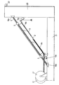
本発明は、特に、控え橋の分野に用いられる。ここで考慮するのは、外被5に囲まれ、鉄塔20とデッキ21の間を延びている控えである(図1)。考慮する控えは、長大な長さ、例えば100mを超える長さを有していてよい。控えは、可能性として、約50またはそれより多くの基本補強部材を有していてよい。
The present invention is used in particular in the field of a suspension bridge. Considered here is a refuge surrounded by the
控えの、複数の補強部材は、外被5内に納められた束の形態にグループ分けされた複数のストランド4から成っている。各ストランドは、張力をかけられ、その2つの端部の所で、それぞれ鉄塔20とデッキ21に位置する2つの固定ゾーン16a、16bに固定されている。固定ゾーン16a、16bに配置された固定手段は、例えば、構造部上に支持され、各ストランドの周りにくさび止めされた円錐台形のジョーが入れられる円錐台形の複数のオリフィスが形成された固定ブロックを有する従来の種類の手段であってよい。
A plurality of reinforcing members, which are reserved, are made up of a plurality of strands 4 grouped in the form of a bundle housed in a
控えを組み立てる方法の最初のステップにおいて、最初のストランド、またはストランドの最初の組が張力をかけられ、その2つの端部の所で固定させられるのと同時に、外被は2つの固定ゾーン間の斜めの経路に沿って所定の位置に配置される。外被5は、その時点から、既に設置されている1つまたは複数のストランド上に載っている。この最初のステップの間に、シャトル2を有する後述の可動器具も同様に外被5内に配置される。
In the first step of the method of assembling the copy, the jacket is placed between the two fastening zones at the same time as the first strand, or the first set of strands, is tensioned and secured at its two ends. It is arranged at a predetermined position along an oblique path. From that point on, the
設置すべき最初のストランド4は、一般に、外被5内で利用可能な空間が、各ストランドを外被5に容易に挿入するのに十分であるかぎり、所定の位置に配置するのに問題を生じさせることはない。これらのストランドは、橋のデッキ上に配置されたリール17から、または、各ストランドが事前に切断されている場合には各ストランドの貯蔵場所から供給される。次に、各ストランドは、例えば、デッキ21から鉄塔20に向かって引き上げることによって、外被内を通される。
The first strand 4 to be installed is generally problematic for placing it in place as long as the space available in the
既に設置されている複数のストランドが絡まるのを防止するために、これらのストランドは、その全長にわたって互いに実質的に平行になるように位置させられている。このために、各ストランドは、2つの固定ブロック上で、互いに対応する位置に配置されている。これは、固定ゾーン16a、16bに配置されたブロックにおいて、互いに対応する位置にある円錐台形のオリフィスに対称に番号を付け、各ストランドを各側で同じ番号のオリフィスに導入することによって行うことができる。
In order to prevent tangling of the already installed strands, these strands are positioned so as to be substantially parallel to each other over their entire length. For this purpose, the strands are arranged at positions corresponding to each other on the two fixed blocks. This can be done by symmetrically numbering the frustoconical orifices at corresponding positions in the blocks arranged in the fixed
固定の前に、外被内を通された各ストランドは張力をかけられ、例えば特許文献1に記載された方法によって、既に張力をかけられている様々なストランドが一様な張力値を有するように張力をかけるのが好ましい。各ストランドは、同一の構成を有し、2つのブロック上の、互いに対応する幾何学的位置に固定されるので、それによって、様々なストランドが2つの固定ゾーン間で互いにほとんど平行な経路に沿って延びるようにすることが可能になる。 Prior to fixing, each strand passed through the jacket is tensioned so that the various strands already tensioned have a uniform tension value, for example by the method described in US Pat. It is preferable to apply tension to. Each strand has the same configuration and is fixed in a corresponding geometric position on the two blocks, so that the various strands follow a path that is almost parallel to each other between the two fixing zones. It becomes possible to extend.
したがって、外被の、アクセスするのが困難な中央部を含む、外被内の各ストランドによって占有される空間は、制限されたままにすることができる。外被は、設置されたストランド上に支持されているので、外被の断面の下部は、以後のストランドを挿入するのに利用可能なままに保たれる。 Thus, the space occupied by each strand within the jacket, including the difficult-to-access center of the jacket, can remain limited. Since the jacket is supported on the installed strand, the lower section of the jacket's cross-section remains available for insertion of subsequent strands.
しかし、しばらくした後、外被内の、利用可能な空間が狭くなるので、新しいストランドを外被5に導入するのが困難になる。この空間を大きくするために、既に固定されたストランド4を、その経路に沿って互いに押し付けるために締め付けるのが有利である。その後、新たなストランド1またはストランドの新たな群が取り付けられたシャトル2(図1)が、外被5の底部に残された利用可能な空間内に配置される。
However, after a while, the available space in the jacket becomes narrow, and it becomes difficult to introduce new strands into the
しかし、しばらくした後、外被内の、利用可能な空間が狭くなるので、新しいストランドを外被5に導入するのが困難になる。この空間を大きくするために、既に固定されたストランド4を、その経路に沿って互いに押し付けるために束ねるように締め付けるのが有利である。その後、新たなストランド1またはストランドの新たな群が取り付けられたシャトル2(図1)が、外被5の底部に残された利用可能な空間内に配置される。
However, after a while, the available space in the jacket becomes narrow, and it becomes difficult to introduce new strands into the
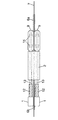
図2に示されているように、締め付け機構3は、断面が、直径が外被の内径に等しいか、またはこれに近い実質的に円形の全体形状の上部を有する型材に従って、既に設置された補強部材を束ねるように締め付けるのが有利である。次に、外被5は、束ねるように締め付けられたストランドの束上に載せられ、最小限の大きさの空間が上部において失われ、したがって、シャトル2が移動するのがより容易になるように、最大限の大きさの空間が外被の下部において自由になる。
As shown in FIG. 2, the clamping mechanism 3 has already been installed according to a mold having a substantially circular overall shape with a cross-section whose diameter is equal to or close to the inner diameter of the jacket. It is advantageous to tighten the reinforcing members together . The
図2に示されている例では、締め付け機構3は、くさび状部材10が挿入された、ストランドの束を取り巻くストラップ11を有している。くさび状部材10は、締め付け型材の断面の下部を形成している。
In the example shown in FIG. 2, the clamping mechanism 3 has a
本発明によれば、シャトル2は、固定ゾーン16aと固定ゾーン16bの間で張力をかけられた1本または2本以上の案内ワイヤに沿って移動する。用いられる案内ワイヤが固定され、例えば、案内ワイヤが、橋のデッキ21上に固定され、案内ワイヤを支持するプーリ上に懸架され、橋の、鉄塔20の近くに配置された質量体によって張力をかけられると(図1参照)、その後、シャトルは、それが固定ゾーン16aと固定ゾーン16bの間を移動する間、この案内ワイヤに沿って滑る。対照的に、案内ワイヤが両固定ゾーンの間を移動可能である場合、シャトル2は案内ワイヤに取り付けられ、その移動に従う。用いられる案内ワイヤは、直径が例えば2mm程度の高強度スチールワイヤであるのが有利である。
According to the present invention, the
新たなストランド1、あるいは、好ましくは設置の効率を向上させるために、ストランド1の新たな群を、デッキ21から橋の鉄塔20に向かって引き上げる前に、このストランドまたはストランドのこの群はシャトル2に連結される。
Before the
図1に示されている第1の実施形態では、ストランド1の新たな群の引き上げは、シャトル2を、シャトル2に連結され、鉄塔20上に配置された引き上げウィンチ15aによって引っ張られる小ケーブル6aを用いて引っ張ることによって行われる。シャトル2は、両固定ゾーンの間で張力をかけられた案内ワイヤ7上を滑る。これと対称に、他の小ケーブル6bをシャトル2に連結し、下向きに下降ウィンチ15bまで延ばすことができる。この下降ウィンチ15bは、引き上げられた新たなストランド、またはストランドの新たな群がシャトルから分離された後に、シャトル2を再下降させるために作動させられる。
In the first embodiment shown in FIG. 1, a new group of
引き上げウィンチ15aによって新たなストランド1を引き上げる間、小ケーブル6bおよびシャトルに逆方向に応力をかけるために下降ウィンチ15bも作動させるのが有利である。同様に、ウィンチ15bによってシャトル2を戻す間、小ケーブル6bおよびシャトルに逆方向に応力をかけるために引き上げウィンチ15aも作動させられる。これらの構成は、シャトル/小ケーブルの組立体が、外被5の底部の所で移動させられる間常に張力を受けることを意味しており、したがって、外被に沿ったこの組立体の経路が一様になることが保証される。
While pulling up the
後述するように、シャトル2は、外被内の、利用可能な空間が、既に設置されたストランドによって制限されている時でも、外被5内を移動させることができるように、小さい寸法を有している。したがって、このようなシャトルによって、外被内で無駄になる空間が、最大限に減らされるため、直径は小さいが多数のストランドを有する控えを組み立てることが可能になる。シャトル2は、ストランド1の、設置すべき群の断面積よりも小さい断面積を有するのが有利である。
As will be described later, the
このような小さいシャトルは、特に、その寸法が小さく重量が軽いので、特に、シャトルによって搬送されるストランドに蓄積された捩れ力のために、シャトルが外被5内で引き上げられる時に自転するのを避けることができない。この運動は、一方では、群の各ストランド1間の、他方では、ストランド1と小ケーブル6aおよび6bの間の絡まり、すなわち捩れを発生させる。さらに、シャトル2は外被内の少なくとも1本の案内ワイヤに沿って移動するので、絡まりはこれらの案内ワイヤも巻き込む。特に、上述の実施形態では、絡まりは案内ワイヤ7と小ケーブル6aの間、小ケーブル6bとストランド1の間で起こる。絡まりは、上述の様々な部材間で起こるある数の捩れからなっている。
Such a small shuttle is especially small in size and light in weight, so that it will rotate when the shuttle is pulled up in the
設置すべきストランド1がこのように絡まると、控え内に設置される複数のストランド間に求められる平行性が守られないので、ストランド1に、固定ゾーン16aや16bに固定するために張力をかけることができなくなる。したがって、これらのストランドが最終的に設置される前にこれらのストランドの絡まりを解消する必要がある。
If the
図1に示されている実施形態では、シャトル2が、引き上げウィンチ15aを用いて小ケーブル6aによって引き上げられている時に自転すると、それによって、特に、小ケーブル6aと、シャトル2が滑る案内ワイヤ7の間での絡まりが引き起こされる。したがって、この絡まりは、案内ワイヤ7の、シャトル2と鉄塔20の間を延びている長い部分(上流部分)で起こる。
In the embodiment shown in FIG. 1, when the
シャトル2が外被5の頂部、すなわち、固定ゾーン16aの近くに一旦達すると、小ケーブル6aと案内ワイヤ7の間に生じている絡まりを検出することができる。このために、例えば、小ケーブル6aと案内ワイヤ7の間に生じている捩れの数が数えられ、捩れの向きも測定される。シャトル2の引き上げ時に形成された全ての捩れが外被の出口まで移動させられているので、この検出は容易である。したがって、絡まりは、外被5の出口の所の小さい長さ上で観察することができる。
Once the
次に、検出された絡まりは、シャトルをその主軸線を中心として、検出された絡まりと逆方向、すなわち、検出された捩れの向きと逆方向に、必要に応じて手動で自転させることによって解消される。実行すべき回転の数は、検出された捩れの数に等しい。 Next, tangling is detected, about its main axis the SHUTTLE, detected entanglements opposite direction, i.e., in the direction opposite to the direction of the detected torsion manually be bicycles as needed Is eliminated. The number of rotations to be performed is equal to the number of twists detected.
実際、小ケーブル6aと案内ワイヤ7の間の捩れの数は、複数のストランド1同士の間、ストランド1と小ケーブル6bの間、および、ストランド1と、案内ワイヤ7の、シャトル2と底部の固定ゾーン16bの間を延びている部分(下流部分)の間に生じている捩れの数に等しい。したがって、上流部分において小ケーブル6aと案内ワイヤ7の間に検出された捩れを解消する上述の操作によって、同様に、下流部分、特に、複数のストランド1の間に生じている絡まりを解消することができる。したがって、この手法によって、引き上げられたストランドに張力をかけ、鉄塔20上に固定する前に、引き上げられている複数のストランド同士、および引き上げられているストランドと既に設置されているストランド4の全体の平行性を回復することが可能になる。
Actually, the number of twists between the
絡まりが解消された後、引き上げられたストランドは、固定ゾーン16aと固定ゾーン16bの間で張力をかけ、設置される全てのストランドの設置が進行するにつれてそれらのストランドに対する張力が等しくなるように前述の方法に従って固定するために、シャトル2から分離される。
After the entanglement is eliminated, the pulled strands are tensioned between the fixing
この実施形態において、シャトルと、引き上げられたストランドが分離されたらすぐに、組み立てるべきガイドの全てのストランドが設置されていない限り、ストランド1の新たな群を引き上げるのにシャトルを用いるために、シャトルをその引き上げと概ね同様に再下降させるのが有利である。したがって、シャトル2は、小ケーブル6bと下降ウィンチ15bの協働作用の結果として橋のデッキ21の方へ駆動される。この戻りの間、シャトルは再び自転し、したがって、案内ワイヤ7と小ケーブル6bの間の下流部分に絡まりを発生させる。
In this embodiment, as soon as the shuttle and the lifted strands are separated, the shuttle is used to lift the new group of
この絡まりは、シャトル2が固定ゾーン16bの近くに到達した時に外被5の出口で検出される。次に、案内ワイヤ7と小ケーブル6bの間だけでなく、同時に、案内ワイヤ7と小ケーブル6aの間の平行性も取り戻すために、絡まりが解消させられる。前と同様に、この絡まりの解消は、外被5の出口の所で案内ワイヤ7と小ケーブル6bの間に捩れが検出されるかぎり、シャトルをその主軸線を中心として自転させることを含んでいる。この操作は、案内ワイヤ7と小ケーブル6bの間で絡まりが検出されるかぎり、すなわち、検出された捩れの数に等しい回数だけ、捩れの向きと逆方向に繰り返される。装置は、その後、新たなストランド1およびストランド1の新たな群を設置できるように操作可能である。
This entanglement is detected at the exit of the
図3は、2つのストランド1を有するのが有利な新たな群を引き上げるのを可能にする可動器具の例を示している。各ストランド1は、図3の左側端部の所で分かるように外被によって覆われている。各ストランドの端部12は剥き出しにされている。さらに、各ストランドは、図4の断面図から分かるように、中央ワイヤ13の周りに撚られた6本の周辺ワイヤから成っている。剥き出しにされた各ストランド1の端部の所で、6本の周辺ワイヤは、中央ワイヤ13のみを維持するように切断されている。したがって、中央ワイヤ13のみがシャトル2に連結されている。この構成によって、シャトル2の断面積をかなり小さくすることが可能になる。
FIG. 3 shows an example of a movable instrument that makes it possible to pull up a new group, which is advantageous to have two
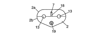
有利な実施形態において、両ストランド1の両中央ワイヤ13は、図5に示されているように、中央ワイヤ13を導入するためにシャトル2に設けられた長手方向の複数の穴13に単純に導入されている。ストランド1の中央ワイヤ13の端部をそれぞれ入れるために、複数の個々の連結器9をシャトルの出口に位置させるのが好ましい。各中央ワイヤ1は、それに対応する連結器9に、例えば、互いに対置された2つのキー14によって固定されている。このようにして、連結器9はストランド1がシャトル2から抜け出るのを防いでいる。シャトルが小ケーブル6aおよび引き上げウィンチ15aによって引き上げられる際、各連結器はシャトルに接触した状態に維持され、したがって、各ストランド1が引き上げられるのを保障する。
In an advantageous embodiment, both
さらに、図示の例では、案内ワイヤ7は、2つのストランド1間の、上部の曲線三角形内に納められるように位置させられている。このようにして、案内ワイヤ7がストランドの群を越える空間を占めないようになっている。さらに、案内ワイヤを受け入れ、シャトル2がこのワイヤに沿って滑るのを可能にするために、溝18がシャトル2に設けられている(図5参照)。
Further, in the illustrated example, the
さらに、小ケーブル6aおよび6bがシャトル2に連結されている。したがって、2本の小ケーブルの各々の端部を各側に受け入れるために、穴19をシャトルに設けることができる。この穴19は、ストランド1の群と、自身の断面積が最小限であるのが有利なシャトル2とから成る組立体の断面において、それ自体が最小限の空間を占めるように位置させられている。さらに、穴19は、両ウィンチの小ケーブルをシャトル内に固定するロックねじ部(図示せず)を有している。
Further,
シャトル2は、例えば互いに係合させることによって互いに連結させることができる別々の2つの部分2aおよび2bから構成されているのが有利である。2つの部分を外すことも同様に可能である。この場合、両穴13は、シャトルの2つの部分の間に形成するのが有利である。したがって、同様に、溝18は、シャトルの2つの部分間の分割面に到達させることができる。溝18は、シャトル2の上部上に到達させることもでき、その場合、溝18は、その後、案内ワイヤ7がシャトルから逃げるのを防ぐために、シャトルの走行中、覆われる。
The
本発明の、図1に示されている実施形態によれば、および図3から5に示されている可動器具の構成では、引き上げウィンチ15aが可動器具をまだ頂部の固定ゾーン16aのできるだけ近くまで搬送していないと仮定して、設置すべきストランド1の移動を、頂部の固定ゾーン16aの所まで完了することが可能である。この場合、シャトル/連結器組立体が、引き上げウィンチ15aによって許容される移動の終点に到達したら、各連結器9を、固定ゾーン16aの、対応するストランドを固定させるべき穴を通過している、引き上げ用の小ケーブルに連結し、補助引き上げウィンチ22に連結するのが有利である。その後、この補助装置によって、各ストランドをその固定ゾーンまで搬送することが可能になる。
According to the embodiment of the present invention shown in FIG. 1 and in the configuration of the movable instrument shown in FIGS. 3 to 5, the lifting
連結器と、それに結合される引き上げ用の小ケーブルの連結は、安全上の理由で、引き上げられたストランド1とシャトル2を分離する前に行うのが好ましい。その後、分離は、単にシャトルの部分2aと2bの連結を解除することによって行われる。ストランド1がシャトルから分離されたすぐに、シャトル2を橋のデッキ21の方へ再び下降させるために、案内ワイヤ7をシャトル2の溝18に慎重に再導入して、必要に応じて、シャトルの2つの部分を連結するのが好都合である。
The connection between the coupler and the small lifting cable connected thereto is preferably performed before separating the pulled
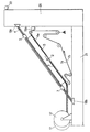
図6は、本発明の、図1の実施形態に代わる一実施形態を示している。この第2の実施形態では、下降ウィンチ15bは無しで済まされている。さらに、2本の案内ワイヤ7aおよび7bが使用されている。これらの案内ワイヤはそれぞれループを形成しており、その連結点は、対応する案内ワイヤの、連結された両端部を囲む、管状に曲げられたスリーブ23によって、シャトルの領域に設けるのが有利である。これらのループは、控えの外被5の外側に部分的に続いている経路に沿っている。この経路は、図示されている、プーリのシステムによって形成されている。さらに、図6において、デッキ21の近くに配置されたモータ手段Mによって、案内ワイヤ7aおよび7bを、矢印によって示されている方向(すなわち、外被5の領域内の位置で見て、固定ゾーン16aから固定ゾーン16bに向かう方向)、および必要に応じて逆方向に駆動することが可能になっている。
FIG. 6 shows an embodiment of the present invention that replaces the embodiment of FIG. In the second embodiment, the lowering
用いられるプーリは、シャトル2が取り付けられた案内ワイヤの数に等しい数、すなわち、本実施形態では2つの溝を有しているのが有利である。同様に、プーリは、案内ワイヤの長さを調整する機構を有していてよい。このような調整機構が、図6では、案内ワイヤ7aおよび7bによって形成されたループの右側部分に示されており、すなわち、2つのプーリが、鉄塔20の近くの、互いに近い各高さに固定されている。案内ワイヤは、移動可能な第3のプーリによって下方に変位させられている。案内ワイヤの張力を維持するために、質量体がこの第3のプーリに懸架されている。前の控えよりも長い新たな控えを組み立てる際には、用いられる案内ワイヤは、固定ゾーン16aと固定ゾーン16bの間を延びるように、より長くしなければならない。その場合、調整機構は、案内ワイヤが張力をかけられたまま、同時に、新たな控えの外被の全長に及ぶように、可動プーリを鉄塔20上の両固定プーリから隔てる距離を修正される。通常、新しい控えが前の控えよりも上に配置される場合、可動プーリは固定プーリに近づけられ、このように距離が短くなることによって、新たな控えの長さに合わせて案内ワイヤの長さを長くすることができる。
The pulleys used advantageously have a number equal to the number of guide wires to which the
シャトル2は案内ワイヤ7aおよび7bに取り付けられ、このことは、第1の実施形態とは対照的に、シャトル2が、案内ワイヤ7aおよび7b上を滑らずにその動きに従うことを意味している。このために、案内ワイヤは、例えば、案内ワイヤが、オペレータによって操作されないかぎりシャトルから抜け出る可能性を生じないように、シャトル2の溝内に挿入されていてよい。この挿入は、例えば、図7および9に示されているように、各案内ワイヤの、管状に曲げられたスリーブ23の領域で行うことができる。しかし、シャトルの断面は、図9および10に示されているように、小さく保たれ、前述の場合に類似している。厳密に言えば、小ケーブル6aはシャトル2に上流側の面上で連結することができ、例えば、この面の中央に配置された穴19’内に導入され、このようにして、シャトルの大きさが周囲で不必要に大きくなるのが回避される。案内ワイヤ7aおよび7bに関しては、これらのワイヤは、この場合も、シャトルの断面積を制限するために、例えば、図8〜10に示されているように両ストランド1の間を通過するように配置されている。
The
同様に、小ケーブル6aを2つの連結器9の一方に連結してもよい。この場合、連結器9は、組立体の引き上げの間、シャトルの上流側に配置されるのが好ましく、その場合、シャトルは、図12に示されている種類のシャトルであってよい。
Similarly, the
この第2の実施形態において、ストランド1の新たな群を保持するシャトルの引き上げは、第1の実施形態と同様に行われ、すなわち、引き上げウィンチ15aに連結された小ケーブル6aによって、シャトル2を頂部の固定ゾーン16aの方へ駆動することが可能になっている。シャトルが引き上げられる間にそれ自体を中心として回転することによって、一方で、引き上げられたストランド1同士が絡まり、また、ストランド1と案内ワイヤ7aおよび7bが絡まり、また、場合によっては、既に設置されているストランド4の束とも絡まるだけでなく、案内ワイヤ7aと7bの間で互いに、および案内ワイヤ7aおよび7bと小ケーブル6aとの間で対応する絡まりも起こる。その後、引き上げられたばかりのストランド1と、既に設置されているストランド4の束の平行性が、両案内ワイヤと小ケーブル6aの絡まりを検出し、次に頂部の固定ゾーン16aの近くで組立体の絡まりを解消することによって回復させられる。前述の場合と同様に、この絡まりの解消は、両案内ワイヤと小ケーブル6aの間に形成され、検知された各捩れについて、絡まりが両案内ワイヤと小ケーブルの間にもはや検知されなくなるまで、シャトル2を捩れと逆方向に回転させることを含む。
In this second embodiment, the shuttle that holds the new group of
もちろん、図7に示されているように、シャトル2と、設置すべき群の新たな各ストランドと結合された両連結器からなる可動器具は、ストランドの、この第2の実施形態による引き上げ時に、各ストランドを、補助引き上げウィンチ22に連結された小ケーブルを用いて、各ストランドの固定点まで引き上げるのを可能にするのに有利に用いることができる。図7に示されている例では、シャトル2が連結器9の上流側に配置されているため、各ストランド1をシャトル2内にしっかりと保持しなければならないことが分かる。特に小ケーブル6aが一方の連結器9に連結される場合、互いに係合可能で連結を外すことが可能な2つの部分から成るシャトル構造も同様に考えられる。
Of course, as shown in FIG. 7, the movable device consisting of the
本発明の第2の実施形態では、下降ウィンチに連結された小ケーブルは利用できない。したがって、デッキ21の方へのシャトル2の再下降は他の手段によって行われる。今問題としているケースでは、シャトルは、モータ手段Mの、案内ワイヤに対する、それらを図6に示されている方向に駆動する作用の結果として再下降させられるのが有利である。厳密に言えば、シャトル2は、図示されている例では案内ワイヤ7aおよび7bに取り付けられている。したがって、両案内ワイヤによって形成された両ループをモータ手段Mによって運動させることによって、シャトルを鉄塔20からデッキ21まで駆動することができ、デッキ21の所で、シャトルを、ストランドの、その後の引き上げ時に用いるために元に戻すことができる。
In the second embodiment of the present invention, the small cable connected to the descending winch cannot be used. Therefore, the re-lowering of the
この再下降時に、シャトル2が自転し、したがって、この時にシャトルを保持する働きをするのが有利な小ケーブル6aと、案内ワイヤ7aおよび7bの間に絡まりを生じさせる恐れが再びある。これらの部材の直線性を回復するために、シャトルが外被5の、デッキ21の近くの出口に達した時に、案内ワイヤ7aと案内ワイヤ7bの間の絡まりが検出される。これらの案内ワイヤの絡まりは、シャトル2を、案内ワイヤ7aと案内ワイヤ7bの間に検出された捩れの数に等しい回数だけ、捩れの向きと逆方向に自転させることによって解消される。この絡まりの解消によって、両案内ワイヤの、シャトル2と引き上げウィンチ15aの間を延びている部分(上流部分)において両案内ワイヤと小ケーブル6aの間に形成された絡まりが対称に解消される。
During this re-lowering, the
したがって、単一の案内ワイヤでは、その案内ワイヤと、引き上げ用の小ケーブル6aの間の、上流部分における絡まりを検出することができないため、この実施形態では、少なくとも2本の案内ワイヤを用いることが必要である。厳密に言えば、この案内ワイヤは、シャトルの下降時にその下流部分において、2本の別々のワイヤの間の巻き付きよりも検出するのがずっと難しい、単一の案内ワイヤ自身の捩れを生じさせられる。
Accordingly, in this embodiment, since a single guide wire cannot detect an entanglement in the upstream portion between the guide wire and the small pulling
図11に示されている第3の実施形態によれば、小ケーブルが、ストランド1の新たな群を引き上げ、または、シャトル2を再下降させるのにもはや用いられていない。第2の実施形態と同様に、シャトル2は2本の案内ワイヤ7aおよび7bに取り付けられている。案内ワイヤ7aおよび7bは、ストランド1の新たな群を引き上げる間シャトルを引っ張れるほど十分に頑丈でなければならない。したがって、この場合、案内ワイヤの直径はわずかに大きくなっている。
According to the third embodiment shown in FIG. 11, the small cable is no longer used to pull up a new group of
前述の場合と同様に、両案内ワイヤはループ状にされ、必要に応じて、案内ワイヤの、設置すべき控えの外被5内に含まれる長さを調整する機構を有する一組のプーリによって形成される経路に沿って移動する。
As in the previous case, both guide wires are looped and, if necessary, by a set of pulleys having a mechanism for adjusting the length of the guide wire contained within the
第3の実施形態において、モータ手段Mは、図11の矢印によって示されている方向、すなわち、ループの、外被5内に配置された部分の領域の位置で見て、デッキ21から鉄塔20の方へ向かう方向、および、必要に応じて逆方向へ案内ワイヤ7aおよび7bを駆動するように構成されている。
In the third embodiment, the motor means M is arranged from the
したがって、ストランドの新たな群の引き上げは、モータ手段を作動させ、それによって、両案内ワイヤを、したがって、暫定的に両案内ワイヤと一体になったシャトル2を鉄塔20の方へ駆動することによって行われる。シャトルの、上昇時の自転に伴う絡まりは、外被5の出口の所で2本の案内ワイヤ7aと7bの間に形成された捩れを観測することによって検出される。この捩れの解消は、シャトルを、捩れの数に等しい回数だけ逆方向に自転させることによって、引き上げられた複数のストランド1の絡まりが下流部分で対称に解消されて行われる。
Thus, the pulling up of the new group of strands activates the motor means, thereby driving both guide wires and thus the
シャトル2の構造は、引き上げ、または下降用の小ケーブルを受け入れる空間を確保する必要がないので、前述の場合とわずかに異なっている。対照的に、両案内ワイヤ、および必要に応じて、各案内ワイヤを囲む、管状に曲げられたスリーブ23を導入するのに十分な両ハウジングをシャトル内に設けなければならない。同様に、互いに係合可能で連結を外すことができる2つの部分の形態のシャトル構造が有利である。
The structure of the
もちろん、シャトル2に加えて、上述のように、新たに引き上げられる各ストランド1用の個々の両連結器を用いることも可能である。これらの連結器は、補助引き上げウィンチ22に連結された比較的短い小ケーブルと共に、複数のストランドの移動を固定点まで完了させる働きをするのが有利である。
Of course, in addition to the
この第3の実施形態では、各引き上げ後に、外被5内でシャトルを再下降させないようにすることが可能である。この場合、モータ手段Mは、常に、図11に矢印で示されている同じ方向に案内ワイヤ7aおよび7bを駆動する。その場合、後続のストランドの引き上げは、他の各シャトルによって行われる。多数のシャトルを用いる必要があるが、このことは、この設置を遅くする、シャトルの再下降段階がないので、控えの設置時に時間が節約されることによって概ね埋め合わされる。
In the third embodiment, it is possible to prevent the shuttle from being lowered again in the
しかし、同様に、モータ手段によって両案内ワイヤの駆動方向を逆転させることにより、外被5内のシャトル2を再下降させることも可能である。この場合、案内ワイヤ7aおよび7b同士の絡まりの解消は、本発明の、上述の第2の実施形態と同様に、外被5の底部の所で行うことができる。
However, similarly, the
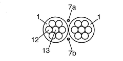
本発明の第2および第3の実施形態の有用な手法によれば、案内ワイヤ7aおよび7bによって形成されたループの、外被5の外側の部分は、他の控えの組立てを行うために用いられる。図13に示されているこの手法は、各控えが同じ鉄塔20からデッキ21の2つの縁部上に対称に設置される橋に対して特に有利である。したがって、橋の鉄塔を通る、デッキの長手方向軸線26によって示された長手方向対称面に関して対称な2つの控え24と25を同時に設置することが可能である。
According to the useful technique of the second and third embodiments of the present invention, the part of the loop formed by the
したがって、両案内ワイヤは、2つの対称な控えの各外被内に導入され、それぞれ、それ自体でループ状にされる。一例として、本発明の第3の実施形態の枠内において、第1の控え24の外被内で、案内ワイヤ7aおよび7bがデッキ21から鉄塔20の方へ駆動され、したがって、これらの案内ワイヤに取り付けられたシャトルが引き上げられる時、同じ両案内ワイヤが鉄塔20からデッキ21の方へ駆動され、したがって、これらの案内ワイヤに取り付けられ、第1の控えとは対称な控え25の外被内に配置された他のシャトルが下降する。逆に、第1の控え24の外被内のシャトルの再下降の間、第1の控えと対称な控え25の外被内に配置されたシャトルが、頂部の固定ゾーンの方へ駆動される。案内ワイヤの絡まりの解消操作に関しては、これらの操作は、以下の制約を伴って、上述のように行われる。この制約は、第1の控えと対称な控え25について橋のデッキの近くで絡まりが解消させられるのと同時に、第1の控え24については鉄塔の近くで絡まりが解消させられるということである。
Thus, both guide wires are introduced into the respective jackets of the two symmetrical stays and are each looped on their own. As an example, within the frame of the third embodiment of the present invention,
2つの対称な控えにおける両操作の、このような同期によって、これらの2つの控えに各ストランドをほぼ同時に設置することが可能になり、このことは、このような橋の控えの設置においてかなりの時間が節約されることを意味している。 This synchronization of both operations in two symmetrical stands allows the strands to be installed almost simultaneously in these two stands, which is a considerable amount in the installation of such bridge stands. It means saving time.
Claims (27)
前記複数の補強部材は、前記外被内に納められ、それぞれが第1の固定ゾーン(16a)および第2の固定ゾーン(16b)に個々に固定された状態で設置され、
前記複数の補強部材の設置は、Nを1または2以上の数として、N個の補強部材から成る群ごとに行われる、控えを組み立てる方法において、
前記外被と、前記複数の補強部材のうち、いくつかの補強部材(4)とが設置された後で、
a) 前記第2の固定ゾーンの近くにおいて、N個の補強部材(1)から成る新たな群を、前記外被の内側に配置されたシャトル(2)に連結するステップと、
b) 前記シャトルを、駆動・案内手段(6a,6b,7,7a,7b,15a,15b)によって前記第1の固定ゾーンの方へ駆動するステップと、
c) 前記シャトルが実質的に前記第1の固定ゾーンの近くに到達した時に、前記駆動・案内手段同士の絡まりが、実質的に前記シャトルと前記第1の固定ゾーンの間に含まれる部分において検出されるかぎり、前記シャトルをその主軸線を中心として前記絡まりと逆方向に回転させるステップと、
d) 前記N個の補強部材から成る前記新たな群を前記シャトルから分離させるステップと、
e) 前記新たな群の補強部材に前記第1の固定ゾーンと前記第2の固定ゾーンの間で張力をかけるステップと、
f) ステップ(a)から(e)を、前記複数の補強部材の設置が完了するまで繰り返すステップと、を含むことを特徴とする方法。 A tilted envelope (5), each other physician substantially parallel to, a method of assembling a copy having a bundle comprising a plurality of reinforcing members tensioned, the,
The plurality of reinforcing members are housed in the jacket, and are installed in a state where each of the reinforcing members is individually fixed to the first fixing zone (16a) and the second fixing zone (16b),
Wherein the installation of the plurality of reinforcing members, the N as one or more numbers, is performed for each group of N reinforcement member, a method of assembling a copy,
When the outside of the, after the plurality of reinforcing members, where the number of the reinforcing member (4) is installed,
a) in the vicinity of the second fixing zone, the steps of connecting a new group of N reinforcement member (1), the shuttle (2) which is arranged inside the envelope,
b) driving the shuttle towards the first fixed zone by drive / guide means (6a, 6b, 7, 7a, 7b, 15a, 15b);
c) when the shuttle reaches the vicinity of substantially the first fixing zone, fault Mari between said driving and guiding means is included between the substantially the shuttle first fixing zone Rotating the shuttle about its main axis in the opposite direction of the entanglement as long as it is detected in the part;
a step of separating the new group consisting of d) the N reinforcement member from the shuttle,
a step of applying a tension between the said first fixing zone reinforcement member e) the new group second fixing zone,
and f) repeating steps (a) to (e) until the installation of the plurality of reinforcing members is completed.
Applications Claiming Priority (1)
| Application Number | Priority Date | Filing Date | Title |
|---|---|---|---|
| FR0310059A FR2858987B1 (en) | 2003-08-20 | 2003-08-20 | METHOD FOR MOUNTING A HAUBAN |
Publications (3)
| Publication Number | Publication Date |
|---|---|
| JP2005068989A JP2005068989A (en) | 2005-03-17 |
| JP2005068989A5 JP2005068989A5 (en) | 2007-03-08 |
| JP4537102B2 true JP4537102B2 (en) | 2010-09-01 |
Family
ID=34112837
Family Applications (1)
| Application Number | Title | Priority Date | Filing Date |
|---|---|---|---|
| JP2004098657A Expired - Lifetime JP4537102B2 (en) | 2003-08-20 | 2004-03-30 | How to assemble a copy |
Country Status (7)
| Country | Link |
|---|---|
| US (1) | US7779499B2 (en) |
| JP (1) | JP4537102B2 (en) |
| KR (1) | KR101215071B1 (en) |
| CN (1) | CN100564685C (en) |
| FR (1) | FR2858987B1 (en) |
| HK (1) | HK1072964A1 (en) |
| MY (1) | MY136050A (en) |
Families Citing this family (10)
| Publication number | Priority date | Publication date | Assignee | Title |
|---|---|---|---|---|
| FR2883376B1 (en) * | 2005-03-17 | 2007-06-15 | Fressinet Internat Stup | METHOD FOR DETECTING RUPTURE WITHIN A STRUCTURE AND SYSTEM FOR IMPLEMENTING THE METHOD |
| DE102006047563B4 (en) * | 2006-10-07 | 2010-06-10 | Steiner, Gerd | Procedure for replacing fully closed ropes of steel cable or composite cable-stayed bridges under traffic |
| CN102782232B (en) * | 2009-12-24 | 2015-02-25 | Vsl国际股份公司 | Method and system for equally tensioning multiple strands |
| US20190264402A1 (en) | 2016-07-27 | 2019-08-29 | Soletanche Freyssinet | Double-sheathed structural cable |
| DE102016225416A1 (en) | 2016-12-19 | 2018-06-21 | Dywidag-Systems International Gmbh | Method for installing a clamping element in an anchor block, holder, in particular for carrying out the method and combination of a holder with a clamping element |
| MX2019009238A (en) | 2017-02-03 | 2019-09-19 | Soletanche Freyssinet | A structural cable having an inner housing. |
| CA3081489A1 (en) * | 2017-11-03 | 2019-05-09 | Soletanche Freyssinet | Sheath for a structural cable of a construction work, methods of installation and maintenance |
| CN109098096B (en) * | 2018-10-19 | 2023-12-19 | 佛山科学技术学院 | Prestressed steel strand anchoring device for bridge construction |
| KR102255412B1 (en) * | 2019-04-25 | 2021-05-24 | 다올이앤씨 주식회사 | Device for cabel installation and method for cable installation using the same |
| CN112081388B (en) * | 2020-08-26 | 2021-06-11 | 中冶建筑研究总院有限公司 | Method and equipment for adjusting intelligent control cable force of group cable |
Family Cites Families (13)
| Publication number | Priority date | Publication date | Assignee | Title |
|---|---|---|---|---|
| DE3138819C2 (en) * | 1981-09-30 | 1986-10-23 | Dyckerhoff & Widmann AG, 8000 München | Method for assembling a tension member running freely between its anchoring points, in particular a stay cable for a stay cable bridge |
| DE3437350A1 (en) * | 1984-08-30 | 1986-03-13 | Ulrich Dr.Ing. e.h. Dr.Ing. 8000 München Finsterwalder | CABLES FOR CONSTRUCTIONS, ESPECIALLY INCLINED CABLE BRIDGES AND METHOD FOR THE PRODUCTION THEREOF |
| DE3437108A1 (en) * | 1984-10-10 | 1986-04-10 | Dyckerhoff & Widmann AG, 8000 München | DEVICE FOR USE IN THE ASSEMBLY OF A TENSION MEMBER OF STEEL WIRE, STRAND, OR THE LIKE |
| JPH0711124B2 (en) * | 1987-11-26 | 1995-02-08 | 鹿島建設株式会社 | Construction method of diagonal cable in cable-stayed bridge |
| FR2652866B1 (en) | 1989-10-05 | 1994-01-07 | Freyssinet International | IMPROVEMENTS IN METHODS AND DEVICES FOR TURNING ON MULTI-STRANDED CABLES. |
| JPH076169B2 (en) * | 1990-05-11 | 1995-01-30 | 住友建設株式会社 | How to install and tension cable-stayed cables |
| FR2702782B1 (en) * | 1993-03-18 | 1995-06-02 | Freyssinet Int & Co | Improvements to methods and devices for mounting the multi-stranded stays of bridges. |
| FR2712900B1 (en) | 1993-11-22 | 1996-02-02 | Freyssinet Int Stup | Improvements to methods and devices for installing discontinuous sheaths on cables and cables thus sheathed. |
| JP2714531B2 (en) * | 1993-12-28 | 1998-02-16 | 株式会社エスイー | How to install diagonal cable |
| DE29506476U1 (en) * | 1995-04-15 | 1996-08-14 | Dyckerhoff & Widmann AG, 81902 München | Device for use in inserting the individual tension elements of a freely tensioned tension member |
| CN1161393A (en) * | 1996-02-06 | 1997-10-08 | 弗里希尼特国际公司 | Suspension device for civil engineering construction and method of construction |
| FR2849070B1 (en) * | 2002-12-18 | 2005-03-04 | Freyssinet Int Stup | METHOD FOR MOUNTING A HAUBAN |
| CN1424465A (en) * | 2003-01-08 | 2003-06-18 | 柳州市威尔姆预应力有限公司 | Low stressed self anchoring method for group anchor steel tension cables |
-
2003
- 2003-08-20 FR FR0310059A patent/FR2858987B1/en not_active Expired - Lifetime
-
2004
- 2004-03-30 JP JP2004098657A patent/JP4537102B2/en not_active Expired - Lifetime
- 2004-08-11 MY MYPI20043264A patent/MY136050A/en unknown
- 2004-08-18 US US10/920,513 patent/US7779499B2/en active Active
- 2004-08-20 KR KR1020040066102A patent/KR101215071B1/en active IP Right Grant
- 2004-08-20 CN CNB2004100851077A patent/CN100564685C/en not_active Expired - Fee Related
-
2005
- 2005-06-30 HK HK05105547.2A patent/HK1072964A1/en not_active IP Right Cessation
Also Published As
| Publication number | Publication date |
|---|---|
| US7779499B2 (en) | 2010-08-24 |
| FR2858987B1 (en) | 2006-02-17 |
| FR2858987A1 (en) | 2005-02-25 |
| US20050055974A1 (en) | 2005-03-17 |
| MY136050A (en) | 2008-08-29 |
| CN1590650A (en) | 2005-03-09 |
| KR101215071B1 (en) | 2012-12-24 |
| JP2005068989A (en) | 2005-03-17 |
| CN100564685C (en) | 2009-12-02 |
| HK1072964A1 (en) | 2005-09-16 |
| KR20050020721A (en) | 2005-03-04 |
Similar Documents
| Publication | Publication Date | Title |
|---|---|---|
| JP4537102B2 (en) | How to assemble a copy | |
| EP1951608B1 (en) | Elevator system | |
| CN101981772B (en) | Method for pulling strands of a cable into a conduit and associated system | |
| CN113756201B (en) | T-structure continuous beam prestressed steel strand pulling method and pulling device thereof | |
| CN102056830A (en) | Rope end fixing device | |
| JP3957680B2 (en) | Assembling method of cable-stayed cable | |
| JP2000054321A (en) | Installation of oblique cable | |
| JP3841616B2 (en) | Elevator main rope replacement method and apparatus | |
| JP3277486B2 (en) | Existing main rope winding device of the elevator | |
| JP2014507348A (en) | Elevator suspension and / or drive device | |
| JP6779192B2 (en) | Wedge type rope stopper | |
| WO2004046008A1 (en) | Method for ensuring and measuring the internal tension of an elevator hoisting rope, and elevator permitting the use of said method | |
| JP2001226082A (en) | Wire rope winding device | |
| US7472534B2 (en) | Method for ensuring and measuring the internal tension of an elevator hoisting rope, and elevator permitting the use of said method | |
| JP2603731B2 (en) | Elevator main rope changing device | |
| JP5883729B2 (en) | Overhead work method and support net | |
| JPH02117581A (en) | Rope exchange method for elevator | |
| JPH09132366A (en) | Control cable device for elevator | |
| JPH0881155A (en) | Main rope length adjusting device of hydraulic elevator | |
| JP3423206B2 (en) | Elevator for construction work | |
| JPH0530755B2 (en) | ||
| RU2565297C2 (en) | Tension member installation method | |
| CN111560835A (en) | Method for installing and tensioning tie rod | |
| KR100616808B1 (en) | Steel wire assembly having connection ring and method for manufacturing thereof | |
| JPH03121333A (en) | Structure for coupling main rope of elevator |
Legal Events
| Date | Code | Title | Description |
|---|---|---|---|
| A521 | Request for written amendment filed |
Free format text: JAPANESE INTERMEDIATE CODE: A523 Effective date: 20070119 |
|
| A621 | Written request for application examination |
Free format text: JAPANESE INTERMEDIATE CODE: A621 Effective date: 20070119 |
|
| A131 | Notification of reasons for refusal |
Free format text: JAPANESE INTERMEDIATE CODE: A131 Effective date: 20081210 |
|
| A601 | Written request for extension of time |
Free format text: JAPANESE INTERMEDIATE CODE: A601 Effective date: 20090310 |
|
| A602 | Written permission of extension of time |
Free format text: JAPANESE INTERMEDIATE CODE: A602 Effective date: 20090313 |
|
| A521 | Request for written amendment filed |
Free format text: JAPANESE INTERMEDIATE CODE: A523 Effective date: 20090410 |
|
| TRDD | Decision of grant or rejection written | ||
| A01 | Written decision to grant a patent or to grant a registration (utility model) |
Free format text: JAPANESE INTERMEDIATE CODE: A01 Effective date: 20100519 |
|
| A01 | Written decision to grant a patent or to grant a registration (utility model) |
Free format text: JAPANESE INTERMEDIATE CODE: A01 |
|
| A61 | First payment of annual fees (during grant procedure) |
Free format text: JAPANESE INTERMEDIATE CODE: A61 Effective date: 20100617 |
|
| FPAY | Renewal fee payment (event date is renewal date of database) |
Free format text: PAYMENT UNTIL: 20130625 Year of fee payment: 3 |
|
| R150 | Certificate of patent or registration of utility model |
Free format text: JAPANESE INTERMEDIATE CODE: R150 Ref document number: 4537102 Country of ref document: JP Free format text: JAPANESE INTERMEDIATE CODE: R150 |
|
| R250 | Receipt of annual fees |
Free format text: JAPANESE INTERMEDIATE CODE: R250 |
|
| R250 | Receipt of annual fees |
Free format text: JAPANESE INTERMEDIATE CODE: R250 |
|
| R250 | Receipt of annual fees |
Free format text: JAPANESE INTERMEDIATE CODE: R250 |
|
| R250 | Receipt of annual fees |
Free format text: JAPANESE INTERMEDIATE CODE: R250 |
|
| R250 | Receipt of annual fees |
Free format text: JAPANESE INTERMEDIATE CODE: R250 |
|
| R250 | Receipt of annual fees |
Free format text: JAPANESE INTERMEDIATE CODE: R250 |
|
| R250 | Receipt of annual fees |
Free format text: JAPANESE INTERMEDIATE CODE: R250 |
|
| R250 | Receipt of annual fees |
Free format text: JAPANESE INTERMEDIATE CODE: R250 |
|
| R250 | Receipt of annual fees |
Free format text: JAPANESE INTERMEDIATE CODE: R250 |
|
| R250 | Receipt of annual fees |
Free format text: JAPANESE INTERMEDIATE CODE: R250 |
|
| R250 | Receipt of annual fees |
Free format text: JAPANESE INTERMEDIATE CODE: R250 |
|
| EXPY | Cancellation because of completion of term |