JP4536904B2 - Polygon mirror, optical scanning device and electrophotographic device - Google Patents
Polygon mirror, optical scanning device and electrophotographic device Download PDFInfo
- Publication number
- JP4536904B2 JP4536904B2 JP2000327138A JP2000327138A JP4536904B2 JP 4536904 B2 JP4536904 B2 JP 4536904B2 JP 2000327138 A JP2000327138 A JP 2000327138A JP 2000327138 A JP2000327138 A JP 2000327138A JP 4536904 B2 JP4536904 B2 JP 4536904B2
- Authority
- JP
- Japan
- Prior art keywords
- polygon mirror
- film
- reflectance
- film thickness
- coating
- Prior art date
- Legal status (The legal status is an assumption and is not a legal conclusion. Google has not performed a legal analysis and makes no representation as to the accuracy of the status listed.)
- Expired - Fee Related
Links
Images


Classifications
-
- G—PHYSICS
- G02—OPTICS
- G02B—OPTICAL ELEMENTS, SYSTEMS OR APPARATUS
- G02B5/00—Optical elements other than lenses
- G02B5/08—Mirrors
- G02B5/09—Multifaceted or polygonal mirrors, e.g. polygonal scanning mirrors; Fresnel mirrors
-
- Y—GENERAL TAGGING OF NEW TECHNOLOGICAL DEVELOPMENTS; GENERAL TAGGING OF CROSS-SECTIONAL TECHNOLOGIES SPANNING OVER SEVERAL SECTIONS OF THE IPC; TECHNICAL SUBJECTS COVERED BY FORMER USPC CROSS-REFERENCE ART COLLECTIONS [XRACs] AND DIGESTS
- Y10—TECHNICAL SUBJECTS COVERED BY FORMER USPC
- Y10S—TECHNICAL SUBJECTS COVERED BY FORMER USPC CROSS-REFERENCE ART COLLECTIONS [XRACs] AND DIGESTS
- Y10S359/00—Optical: systems and elements
- Y10S359/90—Methods
Description
【0001】
【発明の属する技術分野】
本発明は電子写真機器等に用いられる光走査装置に搭載される反射型ポリゴンミラーに関し、特にポリゴンミラーの反射面に形成される膜に関するものである。また、光走査装置および電子写真機器に関する。
【0002】
【従来の技術】
従来よりレーザービームプリンター等の光走査装置においては、特公昭62−36210号公報で開示されているように回転多面鏡(ポリゴンミラー)を介して像担持体面上を光変調された光束(レーザ光束)で光走査することにより画像情報の書き込みや読み出し等を行なっている。
【0003】
図8は光走査装置の要部構成例を示す概略図である。図8において半導体レーザ等の光源部1より射出した光束をコリーターレンズ2により平行光束とし副走査方向にのみ屈折力を持つシリンドリカルレンズ83で集光し、ポリゴンミラー等からなる光偏向器4の偏向反射面4aへ線状に入射させている。コリーターレンズ2とシリンドリカルレンズ83は結像光学系を構成している。該偏向反射面4aで反射偏向させた光束を走査レンズ87を構成する球面よりなる負の屈折力のレンズ87aと直行する2方向で互いに屈折力が異なるトーリック面を有するレンズ87bとによって被走査面89上に導光しスポットを形成する。そして前記偏向器4を回転軸82を中心にモーター85により矢印86方向に回転させることにより被走査面89上における偏向走査面を矢印90方向(主走査方向)に光走査している。
【0004】
ポリゴンミラーには多くの場合、材質としてアルミニウム、プラスチック、ガラス等が用いられている。そして、その反射面に蒸着膜や陽極酸化膜を施すことによって反射率を増加させたり、角度依存性をなくしたり、酸化を防止したりしている。
【0005】
【発明が解決しようとする課題】
多くの場合、光偏向器としてのポリゴンミラーの反射面には真空蒸着法によって反射増加膜等を施しているためその製造誤差による膜厚の違いや製造方法による部分的な膜厚の違いが反射特性のバラつきとなっており、高精度の蒸着装置を必要としたり多層膜構造にして基本の反射率を上げることにより影響を少なくしたり、または、特殊な蒸着法を行なったりする必要があった。このためコストアップに繋がったり膜の自由度を下げる要因ともなっていた。
【0006】
陽極酸化膜の上に非晶質フッ素樹脂膜を施す手法においては陽極酸化膜で反射率の角度依存性を小さくし、非晶質フッ素樹脂膜で結露に対する耐久性を上げている。この陽極酸化工程ではポリゴンミラーの十分な洗浄が必要なため大掛りな装置が必要であり、コストの面での課題があった。
【0007】
上記課題を解決するため回転湿式成膜法により単層膜で上記2例の成膜法より安価に成膜できることが提案されている。ただし、ポリゴンミラーを回転湿式成膜法で成膜する際、反射面全面を塗布液に浸しており、そのために反射面以外にも塗布液が塗られていた。結果的に回転成膜時に反射面以外に付着した塗布液が反射面に集中し、膜厚のバラつきが大きくなる傾向や偶発的な膜の乱れが発生する傾向がみられた。そこで回転湿式成膜法の生産性を向上させ、コストを下げることが課題となっていた。
【0008】
また、近年、光走査装置をコンパクト化する要望からポリゴンミラーに入射する光の入射角範囲は広がる傾向にある。一方反射率の角度一様性のためにポリゴンミラーの反射面には様々な光学膜が形成されているが、それら光学膜にはp偏光の光を全透過する角度(ブリュースタ角)が存在する、つまり、ブリュースタ角を挟んで入射角範囲をとると下層の反射率と一致する角度が必ず存在する。入射角範囲に対して一定の反射率であることが望ましいポリゴンミラーにおいて、一様な膜厚を形成することを前提とすると、特にブリュースタ角より広角側に入射角が広がる場合、反射率の振れ幅は広がり、反射率の角度一様性が得にくい傾向があった。このため、これまでの技術では、広い入射角範囲にも対応できるポリゴンミラーを得るのが難しく、その結果、コンパクトな光走査装置を得るのも難しかった。
【0009】
本発明は、上記問題点に鑑み、低コストで生産性良く製造できるポリゴンミラーとその製造方法を提供すること、低コストで広い入射角範囲において反射率変化が小さいポリゴンミラーとその製造方法を提供することを目的とする。
【0010】
また、安価で、さらにはコンパクトな光走査装置および電子写真機器を提供することを目的とする。
【0011】
【課題を解決するための手段】
本発明は、光を反射する複数の反射面を有するポリゴンミラーにおいて、該反射面上に、波長が680nmの光に対して1.34の屈折率を有する非晶質フッ素樹脂からなる、厚さが88〜109nmの単層膜を有していることを特徴とするポリゴンミラーである。
【0027】
本発明は、また、光源、光源から出射された光を集光して結像する結像光学系、結像された光を反射して偏向する光偏向器、および偏向された光を被走査面に導く走査レンズを備える光走査装置において、該光偏向器が上述のポリゴンミラーを備えることを特徴とする光走査装置である。
【0028】
本発明は、さらに、感光体を帯電させる手段、帯電した感光体を露光して潜像を形成する露光手段、該潜像にトナーを供給してトナー像を形成するトナー像形成手段、該トナー像を転写材に転写する転写手段、および該感光体表面の残留物や異物を除去するクリーニング手段を有する電子写真装置において、
該露光手段として上記光走査装置を備えることを特徴とする電子写真装置である。
【0029】
【発明の実施の形態】
すなわち、本発明は電子写真機器等に用いられる光走査装置に搭載される反射型ポリゴンミラーにおいて、ポリゴンミラーの反射面に波長が680nmの光に対して1.34の屈折率を有する非晶質フッ素樹脂の、厚さが88〜109nmの単層膜が形成されたポリゴンミラーである。なお、本明細書において、この単層膜以外の単層膜に関する記載は、参考用である。
【0030】
上記単層膜を反射面に形成することにより反射面に入射する光の入射角度による反射率の依存性を抑えることができる。これによって、膜厚形成時の厳密な制御が不要となる。
【0031】
前記単層膜は蒸着やスパッタリングに代表される真空成膜法や溶液を用いる湿式成膜法により形成されることが可能であるが、真空成膜法で用いられる装置は設備費が高いため、設備費が安価となり得る湿式成膜法が特に望ましい。
【0032】
湿式成膜法とは所望の膜質または膜質の前駆体を含む溶液を基材に塗布し、前記溶液の溶媒を除去あるいは前駆体を反応させて基材に所望の膜を形成する方法、または溶液中で基材と溶液中の物質との反応により所望の膜を形成する方法である。
【0033】
湿式成膜法としてはディップコートやスピンコートに代表される溶液湿式成膜法や、特にポリゴンミラー基材がアルミニウムの場合には陽極酸化法を用いて酸化アルミの薄膜を形成することも可能であるが、特にコート設備費の負担の少ない溶液湿式成膜法を用いることが望ましい。
【0034】
溶液湿式成膜法とは、膜を形成する物質を溶媒に溶解した溶液を、膜を形成しようとする面に塗布し、これを乾燥または焼成して膜を得る方法である。
【0035】
上記ディップコートやスピンコートは一面もしくは平行した二面を成膜することに向いているが、上記ポリゴンミラーにみられる多面体の成膜には反射面を回転の半径方向にとる回転成膜法が最も望ましい。反射面を回転の半径方向に取るという意味は、反射面の法線が回転半径方向に一致することである。
【0036】
ポリゴンミラーの反射面に成膜する膜材料は、使用条件における耐久性を考慮して適宜決定できるが、例えば非晶質フッ素樹脂、フルオロアクリレート、二酸化珪素などを使用することができる。中でも、オゾンや水に対して不活性であり、水分の影響による腐蝕および基材の腐蝕がみられない非晶質フッ素樹脂が特に望ましく、本発明では特に非晶質フッ素樹脂を用いる。非晶質フッ素樹脂としては例えば構造式(1),構造式(2)で示される物質を用いることができる。
【0037】
【化1】

【化2】
上記非晶質フッ素樹脂の屈折率は680nmの波長の光に対して1.34の屈折率を持ち、この非晶質フッ素樹脂がポリゴンミラーの反射面に88〜109nmに成膜された場合、入射角15〜56°での反射率の変化が±1.0%以内に抑えることができる。
【0040】
上記膜厚の膜を上記回転成膜法で形成する際、成膜過程で溶媒の蒸発速度は遅い方が望ましい。溶媒の蒸発速度は溶媒の沸点が高いほど遅くなるため、特に溶媒の沸点は180℃以上が望ましい。また基材に変形を与えることのない温度で蒸発する溶媒が望ましい。例えばアルミニウム基材を用いた場合には溶媒の沸点は280℃以下であることが望ましい。
【0041】
溶媒に関する他の物性としては、環境による構造の変化が少ないこと、また作業環境上無臭であることがが好ましい。
【0042】
溶媒としては、例えば構造式(3)で示される物質を好ましく用いることができる。
【0043】
【化3】
単層膜が形成される基材としては、アルミニウム、プラスチック、ガラス等、ポリゴンミラーに用いることのできるものであれば、本発明による特段の制限はない。
【0045】
上記基材上に非晶質フッ素樹脂の単層膜が形成されるポリゴンミラーにおいて、回転成膜後に反射面端部に溶液が残ったり、溶液が反射面を筋状に流れた跡が残ったりせず均一な膜を生産性良く形成するには、特に2000〜4000rpm付近で回転させ、更に60秒以上回転させ続けることが望ましい。
【0046】
上記基材上に非晶質フッ素樹脂の単層膜が形成されるポリゴンミラーに対する回転成膜法において、上記回転数および回転時間で成膜する際、所望の膜厚を生産性良く形成するには1.5〜3.0%の溶液を用いることが最も望ましい。
【0047】
上記のような手法により成膜したポリゴンミラーは反射率の角度依存性が少なく、反射面の結露に対する耐久性に優れたポリゴンミラーを極めて安価に製造することが可能となる。つまり、上記のような手法により成膜したポリゴンミラーを搭載した光走査装置や電子写真機器等は従来のそれより安価に製造することができる。
【0048】
回転湿式成膜は、塗布液をポリゴンミラーの反射面に塗布する塗布工程と、これに引き続いて、ポリゴンミラーを回転数を制御しつつ回転させ、所望の膜厚を得る膜厚制御工程とを有する。また通常、塗布液に含まれる溶剤をとばして膜を乾燥・定着させる焼成工程も有する。回転湿式成膜法の塗布工程においては、反射面と回転の軸との最短距離をRiとしたとき、ポリゴンミラーの回転軸からRi以上の領域に塗布液を塗布することが好ましい。塗布領域を支配するのは膜厚を制御する回転に入る前に所望の塗布液を反射面に塗布する過程にある。塗布工程においてRi未満の領域まで塗布したとしても反射面に十分に塗布できていれば膜厚を制御することは可能である。しかし、膜厚のバラツキおよび偶発的な膜の乱れを抑制するという点で、前記Ri以上の領域のみに塗布することが特に望ましい。
【0049】
塗布液を反射面に塗布する方法の一例として、ポリゴンミラーを回転しながら塗布液に反射面を浸すことが挙げられる。この場合、回転軸からRi以上の領域のみに塗布するためには、反射面内の該軸から最も遠い点と該軸との距離をRoとしたとき、回転軸と塗布液面との距離がRo以下で且つRi以上である必要がある。反射面が正n角柱状をなす正n角柱ポリゴンミラーを、正n角柱の中心軸を回転軸として回転させて塗布を行う場合には、Riは反射面に内接する円筒の半径であり、Roは反射面に外接する円筒の半径であり、溶液面と回転軸との距離をRとしたとき、Ri≦R≦Roとなる領域は内接円筒と外接円筒の間の領域となる。このときRo、Riの関係はRi/Ro=cos(円周率/n)となる。
【0050】
また、ポリゴンミラーを回転しながら塗布液に反射面を浸す場合の回転数は塗布液面が激しく波立たないことが好ましい。ここで激しく波立たないとは回転軸からRi未満の領域に塗布液が触れないということである。例えば外接円筒半径20mmの、反射面が六角柱状をなす6面ポリゴンミラーの場合、200rpm以下であることが望ましい。
【0051】
塗布液を反射面に塗布する方法の別の例として、反射面を順次塗布液面に平行にして反射面を塗布液面に接するように浸すことで反射面のみに塗布することが挙げられる。この場合、塗布液が重力に引かれて回転軸からRi未満の領域(正n角柱ポリゴンミラーの場合は内接円筒内側)へ広がらないように一定の回転を保ちながら反射面を塗布液面に接することが特に望ましい。
【0052】
塗布液を反射面に塗布する方法の別の例として、塗布液を含浸した柔らかな媒体を反射面に押し付けることが挙げられる。この場合、前記媒体を反射面に押し付ける際、反射面にキズがつかないように十分に柔らかく、且つ、塗布液を十分に含むことができる媒体を適宜選ぶことができるが、このような媒体として特に発泡スポンジが好適である。
【0053】
塗布液を反射面に塗布する方法の別の例として、塗布液を反射面に吹き付けることが挙げられる。この場合、前記ポリゴンミラーの回転軸に垂直に向けて吹き付け、且つ、塗布液を吹きつける角度は仰角であることが特に望ましい。
【0054】
前記のような手法により反射面に塗布液を塗布するならば、ポリゴンミラー上の塗布領域は回転軸からRi以上の領域(正n角柱ポリゴンミラーの場合は反射面の内接円筒の外側)のみとなり、膜厚のバラつきが小さくなり、高品質な膜が安定して得られ、偶発的な膜の乱れの発生が抑制され、製造不良損失が低下し、ポリゴンミラーを生産性良く、総合的に安価に製造することが可能となる。また、前記のような手法により成膜したポリゴンミラーを搭載した光走査装置や電子写真機器等は従来のそれより高品質で安価に製造することができる。
【0055】
また、反射面に形成する膜に意図的に適切な膜厚分布を持たせることによって、反射率の角度依存性をより一層抑制することができ、よりコンパクトな光走査装置を得ることができ、好ましい。
【0056】
一般的に、膜内で多重反射を起こさないような膜厚であれば、ブリュースタ角より狭い入射角範囲では膜厚が厚くなると反射率は低くなる傾向にある。一方、ブリュースタ角より広い入射角範囲では膜厚が厚くなると反射率は高くなる傾向にある。本発明ではこのことを利用している。
【0057】
つまり、ブリュースタ角の反射率を得られる膜厚は各入射角に対して理論的に求められるため、その膜厚を反射面に忠実に形成させることが、反射率の角度依存性を抑制するという観点から、特に望ましい。
【0058】
P偏光の入射角をブリュースタ角より狭い範囲に限定した場合、均一膜厚で反射率の一様性を実現することは容易である。このとき、ブリュースタ角より広角側では急激に反射率が上昇する。そこで、所望の均一膜厚でブリュースタ角より狭角側の反射率一様性を保証し、ブリュースタ角より広角の光が照射する領域のみ膜厚を薄くすることで理想的な膜形状に近似することができる。膜の全範囲にわたって膜厚を変化させるより成膜が容易であるという点で、この技術も特に望ましい。
【0059】
ポリゴンミラーの成膜法として一般に用いられている成膜法では、任意の膜厚を得るには高度な成膜技術が必要があったり、工数の増加が伴うことが多い。そこで、一様な傾斜の膜厚分布を持たせることで理想的な膜形状に近似することが実生産の観点から望ましい。
【0060】
このような膜厚分布を持つ膜を形成するには、引上げ速度を制御したディッピング法により可能であるが、多面体であるポリゴンミラーには回転湿式成膜法が特に望ましい。回転湿式成膜法においては、溶液を反射面に塗布した後、回転する工程でポリゴン回転の抜け側(回転方向の上流側)に溶液を集め、入り側(回転方向の下流側)から抜け側にかけて膜厚の勾配を持った膜を形成することができる。この勾配は回転数、溶液濃度などで制御することが可能である。
【0061】
本発明において光偏向器の形態としては、本発明のポリゴンミラーを有すること以外は、本発明による特段の制限は無く、電子写真機器に用いることのできる光走査装置であれば、いかなる形態もとり得る。
【0062】
本発明の光走査装置の形態としては、上記光偏向器を備える以外は、特に本発明による制限は無く、電子写真機器に用いることのできる光走査装置であれば、いかなる形態もとり得る。
【0063】
一般的に、光走査装置は、光源、光源から出射された光を集光して結像する結像光学系、結像された光を反射して偏向する光偏向器、および偏向された光を被走査面に導く走査レンズを備える。本発明の光走査装置は、このような構成において光偏向器が上述のポリゴンミラーを備えるものである。
【0064】
本発明の電子写真機器の形態としては、上記光走査装置を備える以外は、特に本発明による制限は無く、例えば、本発明の電子写真機器は電子写真装置を含み、その構成としては、感光体を帯電させる手段、帯電した感光体を露光して潜像を形成する露光手段、該潜像にトナーを供給してトナー像を形成するトナー像形成手段、該トナー像を転写材に転写する転写手段、および該感光体表面の残留物や異物を除去するクリーニング手段を有するものであり、該露光手段として上記光走査装置を備えるものである。
【0065】
【実施例】
(実験例1)
本実験例においては、ポリゴンミラーの基材をエリプソメーターで測定して前記ポリゴンミラーの反射面の光学物性を推定し、更にガラス板上にディップにより塗布液を塗布した後乾燥させて形成した膜を同様にエリプソメーターで測定して膜材料の光学物性を推定したのち、前記ポリゴンミラーに前記膜材料を塗布した際の反射率を数値解析した。
【0066】
ポリゴンミラー基材にはアルミニウムを用い、塗布液としてはフルオロアクリレートを構造式(3)に示す物質(商品名:CT−solv.180:旭硝子社製)に2質量%溶解したものを用いた。
【0067】
図1および図2は上記のようにポリゴンミラーへ膜材料を成膜した場合についての数値解析結果である。図1の横軸は光の入射角であり縦軸は反射率を表す。図2の横軸はポリゴンミラー反射面上の膜の厚さであり、縦軸は入射角15°と56°の反射率の差を表す。図2により反射率の差がゼロとなる膜厚は93nmと166nmとが確認されるが図1より166nmの膜厚では入射角により反射率が大きく変化していることがわかる。したがって反射率の角度差が1%以下である膜厚は84〜104nmであると言える。
【0068】
上記結果とあわせ、同様にして得た他の膜材料についての数値解析結果を表1に示す。
【0069】
【表1】
表1から解るように屈折率が小さいものほど角度差1%以下となる膜厚の幅は広く、反射率の角度依存性を少なくするには屈折率の低いものが適していると言える。より好ましくは非晶質フッ素樹脂が本発明の趣旨に最も適している。
【0071】
〔実施例1〕
本実施例においては、非晶質フッ素樹脂をアルミ基材に塗布し、反射率の角度依存性が抑えられることを示す。
【0072】
代表的な湿式成膜法であるディッピングを行なった。図3に示すように、二つの平行した反射面4aを有するアルミニウムからなるポリゴンミラー(成膜前)4bを塗布液5に全部分浸し、これを引き上げ、焼成して非晶質フッ素樹脂膜を形成し、反射面の反射率を測定した。
【0073】
塗布液には非晶質フッ素樹脂(商品名:サイトップCTL−802:旭硝子社製)を構造式(3)に示す物質(商品名:CT−solv.180:旭硝子社製)に2.0質量%溶解した溶液を用い、引上げ速度を80mm/minで引き上げ、170℃で30分間焼成するとおよそ100nmの膜厚が形成され、そのときの15〜56°の入射角における反射率の変化は1.0%以内に抑えられていた。
【0074】
〔実施例2〕
本実施例においては、多面体のポリゴンミラーに非晶質フッ素樹脂を塗布する場合、本発明における回転湿式成膜法が有効であることを示す。
【0075】
外接円筒直径40mmで、6つの反射面が正六角柱をなすアルミニウムからなる成膜前のポリゴンミラー4bを6枚、図4に示すように軸に通す。2.9%の非晶質フッ素樹脂(商品名:サイトップCTL−802:旭硝子社製)溶液(溶媒は構造式(3)に示す物質(商品名:CT−solv.180:旭硝子社製))を満たした槽内の溶液にポリゴンミラーの反射面を40rpmで回転しながら、1.2mmの深さで浸し、溶液から反射面を離した後2000rpmで120秒間回転させて薄膜を形成し、170℃で30分間焼成をかけた。反射面にはおよそ100nmの非晶質フッ素樹脂膜が6面とも均一に形成され、15〜56°の入射角における反射率の変化は1.0%以内となった。
【0076】
また、このようにして得たポリゴンミラーを結露耐久試験およびオゾン耐久試験を行なった結果から非晶質フッ素樹脂膜が耐湿性・耐オゾン性に優れる膜であることを示す。
【0077】
結露耐久試験において前記非晶質フッ素樹脂を形成したポリゴンミラーを60℃・90%の炉の中で10時間放置し、これを繰返し3回実験を行なった。それぞれの試験の前後での反射率の変化を観たところ、3回目の試験後においても反射率の低下が2.0%以下でありほとんど反射率の変化がないものと言える。また、オゾン耐久試験においては、前記非晶質フッ素樹脂を形成したポリゴンミラーを45℃・95%かつオゾン濃度1ppmの環境下で100時間放置し、実験の前後での反射率を測定した。反射率の低下は全く観られなかった。
【0078】
つまり、結露試験を繰り返し行なった後でさえ2.0%以下の反射率低下に留まり、オゾン耐久試験においては全く変化が観られなかったことから、前記非晶質フッ素樹脂は耐湿性・耐オゾン性に優れており、ポリゴンミラーの反射面の塗布膜として非常に有効である。
【0079】
〔実施例3〕
本実施例においては、外接円筒直径40mmかつアルミニウムからなる6つの反射面が正六角柱をなすポリゴンミラーへ非晶質フッ素樹脂を塗布する場合、均一な膜を形成するのに最適な回転数・回転時間を求めるための手法を示す。
【0080】
回転数・回転時間のみをパラメータにとり、実施例2と同様に回転湿式成膜を行なった。
【0081】
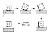
図5は1500rpmかつ120secで回転成膜(ア)し、また2500rpmかつ120secで回転成膜(イ)させた時の前記ポリゴンミラーの反射面の写真であり、図6は図5を補足するイメージ図である。
【0082】
回転時間を120secで固定し、かつ、回転数を1000〜3000rpmで500rpm刻みで回転成膜してみると1500rpm以下では図5−アのような液が反射面端部に残る「液溜り跡」60が現れる場合があった。2500rpm以上では図5−イのような液が前記反射面上を素早く流れていった跡(「流れシミ跡」61)が現れる場合があった。2000rpmで回転させた場合、前記「液溜り跡」は0.5mm以下に抑えられ、前記「流れシミ跡」も確認されなかった。表2に結果をまとめて示す。表中、例えば0/10は、10回試験して0回液溜り跡あるいは流れシミ跡が認められたことを示す。
【0083】
【表2】
1000rpm、1500rpmで120秒間回転させたときに見られる液溜り跡は、120秒回転させた後2000rpmで10秒間回転させることにより防止することができる。また2500rpm、3000rpmで120秒間回転させたときに見られる流れシミ跡は2500rpmで20秒、あるいは3000rpmで15秒回転させた後2000rpmで120秒間回転させることにより防止できる。
【0085】
また、回転数を2000rpmで固定し、回転数を30〜150secで30sec刻みで回転成膜してみたところ90sec以下では前記「液溜り跡」は0.5mm以上確認されることがあり、120sec以上では0.5mm以下となることが確認された。結果を表3にまとめて示す。
【0086】
【表3】
2000rpmで30秒、60秒、90秒回転させたときに発生する液溜り跡は回転時間をのばすことにより防止できる。また30秒、60秒、90秒回転させた後、3000rpmで15秒間回転させても防止することができる。本実施例より装置制作上最も安価な機構を考え、外接円筒直径40mmかつアルミニウムからなる6面ポリゴンミラーに非晶質フッ素樹脂の回転成膜法を適用する場合、回転数を固定した場合には2000rpmで120秒以上回転することが望ましいと言える。上記条件で回転を行うことにより、安価な装置を用いて均一な膜をきわめて安定的に形成することが可能である。
【0088】
〔実施例4〕
本実施例においては、溶液の濃度のみをパラメータにとり、実施例2と同様に反射率の角度差を測定することで最適な液濃度の割り出しを行なった。
【0089】
液濃度を1.5〜4.0wt%の範囲で回転湿式成膜法を適用し(作成された膜の膜厚はそれぞれ異なる)、反射率の角度差を測定した結果を図7に示す。データには若干バラつきが見られたものの大まかな傾向として上に凸の曲線を描き、反射率の角度依存性が最も少なくなると思われる濃度は2.9〜3.0wt%であった。
【0090】
なお、本例において液濃度が1.5%の場合のように角度依存性が大きい場合でも、他の製造条件、例えば回転速度を調整すれば、角度依存性を抑えることが可能である。
【0091】
〔実施例5〕
実施例1〜3のポリゴンミラーをスキャナーモータに装備して回転可能な光偏向器、光源(半導体レーザー)、結像光学系、走査レンズとともに図8に示すように配置して光走査装置を構成した。さらに、この光走査装置を用いて電子写真機器を構成した。ここで電子写真機器としては、感光体を帯電させる手段、帯電した感光体を露光して潜像を形成する露光手段、該潜像にトナーを供給してトナー像を形成するトナー像形成手段、該トナー像を転写材に転写する転写手段、および該感光体表面の残留物や異物を除去するクリーニング手段を有する電子写真装置とし、該露光手段として上記光走査装置を用いた。
【0092】
この電子写真装置を用いて、繰り返し、パターン画像及び写真画像を出力したところ、画質、耐久性ともに従来のポリゴンミラーを用いたレベルに達していた。すなわち、本発明のポリゴンミラーは、従来のポリゴンミラーに要求される性能を満足しており従来のポリゴンミラーに代わって使用しても何ら問題はなかった。
【0093】
〔実施例6〕
本実施例においては、ポリゴンミラーに塗布液を塗布する領域を回転軸からRi以上の領域(反射面内接円筒の外側)のみに塗布することで、膜厚および反射率の角度依存性のバラツキを抑制することができることを示す。
【0094】
外接円筒半径20mm(内接円筒半径Ri=17.3mm)の、反射面が正六角柱をなす6面ポリゴンミラーに非晶質フッ素樹脂を回転成膜法で塗布し、膜厚を制御する回転に入る前に、反射面に塗布液を塗布する為に回転軸と塗布液面との距離をRとした時、表4の条件で実験した。その時の結果を表5に示す。測定回数は各条件につき30である。塗布液は非晶質フッ素樹脂(商品名:サイトップCTL−802:旭硝子社製)を2.7質量%含む構造式(3)に示す物質(商品名:CT−solv.180:旭硝子社製))である。
【0095】
塗布工程の手順としては、40rpmで回転させ、表4に示す距離で10秒間保持した。
【0096】
塗膜形成工程における回転数および回転時間は、2000rpmで120秒とした。
【0097】
塗膜を焼成する条件としては、180℃の加熱炉で40分とした。
【0098】
【表4】
【表5】
反射面内接円筒半径Ri(=17.3mm)を境に各入射角度15°、35°、56°で条件AおよびBが条件CおよびDより反射率のバラツキが小さいと言える。つまり、反射率のバラツキが膜厚のバラツキに他ならないことから、塗布領域が内接円筒の外側に限定されているときが膜厚のバラツキを抑えられ、好ましいことがわかる。また、入射角度15°、35°、56°の反射率の中で最大値と最小値の差を表した「P−P」で比較すると、条件AおよびBが条件CおよびDよりバラツキが半分以下であると言える。つまり、塗布領域が反射面内接円筒の外側に限定されているとき、反射率の角度依存性のバラツキが抑えられ、好ましい。
【0101】
また条件CおよびDにおいて発生した反射率のバラツキ、膜厚のバラツキは反射面内接円の内側に塗布された溶液を除去した後に回転を開始すれば防止することができるが、より安価で簡単な装置構成を考えた場合、上記のような溶液除去手段を用いるよりも反射面内接円外側にのみ溶液を塗布することが望ましい。
【0102】
〔実施例7〕
本実施例においては、ポリゴンミラーヘの塗布領域を回転軸からRi以上の領域(反射面内接円筒の外側)のみに塗布することで偶発的な膜の乱れを抑制することができることを示す。
【0103】
外接円筒半径10mmの、反射面が正四角柱をなす4面ポリゴンミラーにSiO2のゾルケル膜を回転湿式成膜法で塗布し、反射面上に図9(イ)のような液が流れたような跡である「流れシミ」61、或いは反射面端部に液が端部から0.3mm領域に液が残った跡である「液溜り」60が現れる発生率を比較した。塗布液はエチルシリケートを2質量%含むイソプロピルアルコールである。実験条件は表6の通りとした。測定回数は各条件につき120である。
【0104】
塗布工程の手順としては、表6の距離で40rpmで10秒間回転させた。
【0105】
塗膜形成工程における回転数および回転時間は、2000rpmで120秒とした。
【0106】
塗膜を焼成する条件としては、180℃の加熱炉で40分とした。
【0107】
【表6】
表6から分かるように、塗布領域が反射面内接円筒の外側のみの場合(条件AおよびB)の方が反射面内接円筒内側まで塗布領域がある場合(条件CおよびD)よりも、「流れシミ」、「液溜り」共に発生率が低いことが分かる。つまり、膜形状の偶発的な乱れが塗布領域を反射面内接円筒の外側に限定することで抑制され、好ましい。
【0109】
また条件CおよびDにおいて多く発生した流れシミ、液溜り等は、反射面内接円の内側に塗布された溶液を除去した後に回転を開始すれば、それぞれ1.5%以下に抑制することができるが、より安価で簡単な装置構成を考えた場合、上記のような溶液除去手段を用いるよりも反射面内接円外側にのみ溶液を塗布することが望ましい。
【0110】
〔実施例8〕
本実施例においては、回転湿式成膜法において膜厚を制御する回転に入る前に塗布液を反射面に塗布する方法の最も好ましい1例を示す。
【0111】
外接円筒半径20mmの、反射面が正六角柱をなす6面ポリゴンミラーにおいて、回転数を40rpmとし、回転軸と塗布液面との距離Rをパラメータにとり、反射面全面に塗布できるまでの塗布時間をみた。
【0112】
手順を図10に示す。図10では簡単のために、4面ポリゴンミラーを示してある。まず成膜しようとするポリゴンミラーをRi<R<Roとなるように、かつここではポリゴンミラーが塗布液に接しないように塗布液上にセットする。次にポリゴンミラーを回転させると、ポリゴンミラーの角部に液が塗布される(図中10で示す部分)。また回転によってこの液が濡れ広がり、最終的に反射面4a全面に塗布液が塗布される。塗布液は非晶質フッ素樹脂(商品名:サイトップCTL−802:旭硝子社製)(構造式(1))を2.0質量%含む構造式(3)に示す物質(商品名:CT−solv.180:旭硝子社製))である。
【0113】
表7に示した結果から、反射面が塗布液面に完全には浸ることがなくとも、反射面に塗布液が完全に塗れ広がることが分かる。
【0114】
【表7】
次に塗布時間を5sec、回転軸と塗布液面との距離を18.0、19.0mmに固定し、回転数をパラメータにとって上記と同様に塗布した結果を表8に示す。表中、○は塗布液が反射面全体に良好に濡れ広がることを示し、△は5〜20秒でぬれ広がることを示し、×は20秒以内では濡れ広がらないことを示す。この表から分かるようにR=18.0mmでは300rpm以下で塗れ広がることが確認され、R=19.0mmでは160rpm以下で塗れ広がることが確認された。R=18.0mmであっても回転数を300rpm超とすると塗布液面が激しく波立ち、所望の量を塗布できないことが確認され、本実験条件においては、回転数としては200rpm以下とするのが妥当だと言える。
【0116】
【表8】
〔実施例9〕
本実施例においては、回転湿式成膜法において膜厚を制御する回転に入る前に塗布液を反射面に塗布する方法で考えうる代表的な例を以下に示し、塗布状況を表9に示した。ポリゴンミラーは外接円筒半径10.0mm、反射面が正四角柱をなす4面ポリゴンミラー(内接円筒半径7.1mm)とし、塗布液は非晶質フツ素樹脂(商品名:サイトップCTL−802:旭硝子社製)を2.0質量%含む構造式(3)で示す物質(商品名:CT−solv.180:旭硝子社製)である。また試験回数はそれぞれ10である。
【0118】
塗布例Iは実施例7で述べた方法とし、回転数40rpm、塗布時間5sec、回転軸と塗布液面との距離Rを8.0mmとした。
【0119】
塗布例IIは、図11に概略を示すように、まず反射面が塗布液面と平行し、反射面が塗布液面と接するように浸す。一旦反射面を水平にした後塗布液面に近づけて接しさせることも考えられるが、ここでは、塗布された液が反射面内接円筒内側の領域に広がらないようにポリゴンミラーに一定の回転(30rpm)をさせながら反射面が水平になるタイミングで塗布液面を上昇させ、反射面を塗布液面に接しさせて塗布した。
【0120】
塗布例IIIでは、図12に概略を示すように、塗布液を十分に含んだ媒体6を反射面に順次押し付けて反射面のみに塗布液を塗布する。ここでは、前記媒体が十分に塗布液を含有し、反射面にキズを付けないために十分な柔らかさを有した発泡スポンジ(ブリジストン製ホワイトワイパ一)を用いた。
【0121】
塗布例IVでは、図13に概略を示すように、塗布液をノズル7から反射面に噴射することにより、塗布液を反射面に塗布した。ここでは、噴流の流量を10ml/sec、吹き出し断面直径1mmとし、吹き出し方向を仰角70°、ホリゴンミラーを10rpmで回転させながら塗布した。
【0122】
塗布例Vは、塗布例Iと同じ塗布方法で、ただし図14に示すように、回転軸と塗布液面との距離を6.0とした。
【0123】
上記の方法で塗布を行い、回転数2000rpm、回転時間120秒で塗膜形成工程を行い、180℃で焼成して膜を形成し、実施例6と同様に入射角度15°、35°、56°の反射率の中で最大値と最小値の差を表した「P−P」を求めてその標準偏差を算出し(P−Pバラツキ)、流れシミを観察した結果を表9に示す。
【0124】
【表9】
表9からも分かるように、反射面内接円筒の内倒まで塗布領域が存在する塗布例V以外であれば、塗布領域が反射面内接円筒の外側となり、反射率のバラツキ、偶発的な膜厚の乱れ共に極めて良く抑制することができ、好ましいことが確認された。
【0126】
〔実施例10〕
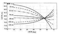
本実施例においては、広範囲のp偏光入射角に対して膜厚分布を持たせることで反射率の角度一様性が得られることを示す。
【0127】
図15は、均一膜厚を形成した場合の膜厚と入射角および反射率の関係を示した一例として、アルミ基材の上にSiO2の均一膜を形成した場合を示した図である。膜厚に関係なく一定の反射率を示す入射角、ブリュースタ角が存在することが確認される。このときブリュースタ角よりも狭角側では膜厚が厚くなるに従い反射率が低下し、逆に、ブリュースタ角よりも広角側では膜厚が厚くなるに従い反射率が増加することが言える。
【0128】
図16ア)はアルミ基材の反射面にSiO2の膜を形成したときの膜厚分布である。ポリゴンミラーの反射面上の位置と光の入射角とは1対1の関係であるので横軸には対応する入射角で表している。この膜厚分布は、次のようにして決めた。すなわち、10〜70°の入射角に対応する各反射面位置において、ブリュースタ角(55°)における反射率(78.8%)が得られる膜厚を算出した。
【0129】
図16イ)はこの膜厚分布のときの反射率を示した図である。この図から上記膜厚分布を形成した場合に入射角に対して反射率が一定であることが確認される。
【0130】
表10は、アルミ基材の上にTiO2、Al2O3、SiO2および非晶質フッ素樹脂(商品名:サイトップCTL−802:旭硝子社製)の膜を均一膜厚でディッピングにより形成した膜について、入射角10〜70°での反射率を示したものである。表中B.A.とはブリュースタ角である。各膜に対してブリュースタ角より狭角側では比較的反射率が一様であるが、ブリュースタ角より広角側では反射率が急激に変化していることがわかる。
【0131】
【表10】
表11はアルミ基材の上に単層で種種の膜をディッピングにより膜厚分布をもって形成し、そのときの反射率を測定した結果である。このとき、ブリュースタ角の反射率と同じ反射率を示す膜厚を計算し、反射面の各位置でその膜厚が形成されるように引き上げ速度を制御して成膜した。表11から分かるように、上記膜厚分布を設けることで反射率が角度に依存せず一様であることが確認された。
【0133】
表10および表11から分かるように、P偏光の入射角範囲が広範囲の場合は上記のような膜厚分布を設けることで反射率の角度一様性が得られることが確認された。
【0134】
【表11】
ブリュースタ角の反射率は、反射面に形成される表層の膜厚に全く依存せず、下層までの反射率を示す。つまり、層数が1層であれば基材の、複数層であれば表層を除いた残りの層としての反射率となる。したがって、下層の材質、層数に関わらず、反射率の角度一様性は表11と同様に上記のような膜厚分布を形成することで実現することができる。
【0136】
〔実施例11〕
本実施例では反射面に形成される膜に対して、P偏光がブリュースタ角より広角に入射する領域の膜厚を薄くすることで反射率の角度一様性が得られることを示す。
【0137】
表12はアルミ基材のポリゴンミラーに種々の膜を形成したとき、ブリュースタ角より狭角側を均一膜厚とし、ブリュースタ角より広角側でその均一膜厚より若干薄くして形成したときの反射率を示している。ブリュースタ角より広角側における膜厚の決め方は、ブリュースタ角における反射率が得られる膜厚とする。ここでは、入射角70°において、ブリュースタ角における反射率が得られる膜厚とした。
【0138】
このとき、表10の場合(全面均一膜厚)よりも反射率の角度一様性が得られていることが確認された。
【0139】
【表12】
〔実施例12〕
本実施例では反射面に形成される光学膜に一様な傾斜の膜厚を設けて反射率の角度一様性が得られることを示す。
【0141】
表13はアルミ基材のポリゴンミラーに種々の膜を形成したとき、膜厚分布に一様な傾斜を設けたときの反射率を示している。この傾斜の決め方は各々の膜材料に応じて反射率変化が最小となる勾配を求める。例えばここでは非晶質フッ素樹脂について膜厚勾配を40%(膜の最も薄い部分を1としたとき、最も厚い部分が1.4)とした。
【0142】
このとき、表10に示す均一膜厚の場合よりも反射率の角度一様性が得られていることが確認された
【0143】
【表13】
〔実施例13〕
実施例5と同様に、実施例10〜12のポリゴンミラーを用いて光走査装置、さらには電子写真機器を構成し、評価を行った。画質、耐久性ともに従来のポリゴンミラーを用いたレベルに達していた。
【0145】
【発明の効果】
以上説明したように、本発明によれば、電子写真機器等に用いられる光走査装置に搭載される反射型ポリゴンミラーにおいて、ポリゴンミラーの反射面に1.45以下の屈折率を有する物質、特に低屈折率膜材料である非晶質フッ素樹脂を回転湿式成膜法により単層で形成することで、真空蒸着法や陽極酸化法に比べ、より安価にポリゴンミラーを製造することが可能である。
【0146】
また、ポリゴンミラーの回転湿式成膜法において、反射面と塗布時の回転軸との最短距離をRiとしたとき、ポリゴンミラーのRi以上の領域のみに塗布液を塗布することで膜厚のバラツキや偶発的な膜の乱れを抑制することが可能であり、ポリゴンミラーの生産性を向上させることができ、従って、ポリゴンミラーを安価にすることが可能となる。
【0147】
このようなポリゴンミラーを備える本発明の光走査装置、さらにはこの光走査装置を備える電子写真機器は、安価に生産することができる。
【0148】
さらに、ポリゴンミラーの反射面に形成される膜に適切な膜厚分布を持たせることで広範囲の入射角に対して反射率の角度一様性が得られる。またこのことより、光走査装置のコンパクト化に貢献し、光走査装置をより安価に製造することが可能である。さらにこのような光走査装置を備える本発明の電子写真機器は、コンパクト化が可能であり、また低コスト化も可能である。
【図面の簡単な説明】
【図1】実験例1に係る膜厚と入射角および反射率の関係を説明するグラフである。
【図2】実験例1に係る膜厚と15〜56°の入射角における反射率の差の関係を説明するグラフである。
【図3】実施例1に係るディッピングを説明する図である。
【図4】実施例2に係る回転湿式成膜法を説明する図である。
【図5】実施例3に係る「液溜り跡」および「流れシミ跡」を説明する写真である。
【図6】実施例3に係る「液溜り跡」および「流れシミ跡」を説明する模式図である。
【図7】実施例4に係る非晶質フッ素樹脂溶液濃度と15〜56°の入射角における反射率の差の関係を説明する図である。
【図8】光走査装置の要部構成例を示す概略図である。
【図9】実施例7に係る膜形状の乱れの模式図である。
【図10】実施例8に係る塗布方法の概略を表した図である。
【図11】実施例9に係る塗布例IIの概略を表した図である。
【図12】実施例9に係る塗布例IIIの概略を表した図である。
【図13】実施例9に係る塗布例IVの概略を表した図である。
【図14】実施例9に係る塗布例Vの概略を表した図である。
【図15】実施例10に係る、アルミ基材にSiO2を形成したとき均一膜厚としたときの入射角と反射率の関係を説明する図である。
【図16】実施例10に係る、アルミ基材にSiO2を形成したとき所望の膜厚分布にしたときの膜厚、入射角および反射率の関係を説明する図である。ア)は入射角に対する膜厚分布状態、イ)はこのときの入射角に対する反射率を説明する図である。
【符号の説明】
1 光源
2 コリーターレンズ
4 光偏向器
4a 反射面
4b ポリゴンミラー(成膜前)
5 塗布溶液
6 塗布液を含んだ媒体(発泡スポンジ)
7 塗布液噴射ノズル
10 塗布液が塗布された反射面の部分
60 液溜り
61 流れシミ
82 回転軸
83 シリンドリカルレンズ
85 モーター
86 回転方向
87 走査レンズ
89 被走査面
90 走査方向[0001]
BACKGROUND OF THE INVENTION
The present invention relates to a reflective polygon mirror mounted on an optical scanning device used in electrophotographic equipment and the like, and more particularly to a film formed on a reflective surface of a polygon mirror. The present invention also relates to an optical scanning device and an electrophotographic apparatus.
[0002]
[Prior art]
2. Description of the Related Art Conventionally, in an optical scanning device such as a laser beam printer, a light beam (laser light beam) light-modulated on the surface of an image carrier through a rotating polygon mirror (polygon mirror) as disclosed in Japanese Patent Publication No. 62-36210. The image information is written and read out by optical scanning.
[0003]
FIG. 8 is a schematic diagram illustrating an exemplary configuration of a main part of the optical scanning device. In FIG. 8, a light beam emitted from a light source unit 1 such as a semiconductor laser is converted into a parallel light beam by a
[0004]
In many cases, the polygon mirror is made of aluminum, plastic, glass or the like. Then, by applying a vapor deposition film or an anodic oxide film on the reflection surface, the reflectance is increased, the angle dependency is eliminated, or oxidation is prevented.
[0005]
[Problems to be solved by the invention]
In many cases, the reflective surface of a polygon mirror as an optical deflector is provided with a reflection-enhancing film or the like by a vacuum deposition method, so that differences in film thickness due to manufacturing errors or partial film thickness differences due to manufacturing methods are reflected. Due to the variation in characteristics, it was necessary to use a highly accurate vapor deposition device, to reduce the influence by increasing the basic reflectivity with a multilayer film structure, or to perform a special vapor deposition method . For this reason, it has led to an increase in cost and a factor of reducing the degree of freedom of the film.
[0006]
In the method of applying an amorphous fluororesin film on the anodized film, the angle dependency of the reflectance is reduced by the anodized film, and the durability against dew condensation is increased by the amorphous fluororesin film. In this anodic oxidation process, the polygon mirror needs to be sufficiently cleaned, so that a large-scale apparatus is required and there is a problem in terms of cost.
[0007]
In order to solve the above problems, it has been proposed that a single layer film can be formed at a lower cost than the above two examples by a rotary wet film forming method. However, when the polygon mirror is formed by the rotary wet film forming method, the entire reflecting surface is immersed in the coating solution, and therefore the coating solution is applied to the surface other than the reflecting surface. As a result, there was a tendency that the coating liquid adhering to the surface other than the reflection surface during the rotation film formation was concentrated on the reflection surface, resulting in a tendency that the variation in film thickness increased or an accidental film disturbance occurred. Therefore, it has been a challenge to improve the productivity of the rotary wet film forming method and reduce the cost.
[0008]
Further, in recent years, the range of incident angles of light incident on the polygon mirror tends to widen due to the desire to make the optical scanning device compact. On the other hand, various optical films are formed on the reflective surface of the polygon mirror for uniform angle of reflectivity, but these optical films have an angle (Brewster angle) that totally transmits p-polarized light. In other words, there is always an angle that matches the reflectivity of the lower layer when the incident angle range is taken across the Brewster angle. Assuming that a uniform film thickness is formed in a polygon mirror that is desired to have a constant reflectivity with respect to the incident angle range, the reflectivity can be reduced especially when the incident angle spreads to the wide angle side from the Brewster angle. There was a tendency that the fluctuation width was wide and it was difficult to obtain the angular uniformity of the reflectance. For this reason, it has been difficult to obtain a polygon mirror that can cope with a wide range of incident angles with conventional techniques, and as a result, it has been difficult to obtain a compact optical scanning device.
[0009]
SUMMARY OF THE INVENTION In view of the above problems, the present invention provides a polygon mirror that can be manufactured at low cost with high productivity and a manufacturing method thereof, and provides a polygon mirror that has a low reflectance change in a wide incident angle range and a manufacturing method thereof. The purpose is to do.
[0010]
It is another object of the present invention to provide an inexpensive and compact optical scanning device and electrophotographic apparatus.
[0011]
[Means for Solving the Problems]
The present invention relates to a polygon mirror having a plurality of reflecting surfaces for reflecting light.surfaceabove,1.34 for light with a wavelength of 680 nmHave refractive indexAmorphous fluororesinConsist ofThe thickness is 88-109nmA polygon mirror characterized by having a single layer film.
[0027]
The present invention also provides a light source, an imaging optical system that focuses and collects light emitted from the light source, an optical deflector that reflects and deflects the focused light, and the deflected light is scanned. An optical scanning device including a scanning lens that leads to a surface, wherein the optical deflector includes the polygon mirror described above.
[0028]
The present invention further includes means for charging the photoreceptor, exposure means for exposing the charged photoreceptor to form a latent image, toner image forming means for supplying toner to the latent image to form a toner image, and the toner In an electrophotographic apparatus having a transfer means for transferring an image to a transfer material, and a cleaning means for removing residues and foreign matters on the surface of the photoreceptor.
An electrophotographic apparatus comprising the optical scanning device as the exposure means.
[0029]
DETAILED DESCRIPTION OF THE INVENTION
That is, the present invention provides a reflective polygon mirror mounted on an optical scanning device used in electrophotographic equipment or the like, on the reflective surface of the polygon mirror.1.34 for light with a wavelength of 680 nmHave refractive indexAmorphous fluororesinofThe thickness is 88-109nmIt is a polygon mirror in which a single layer film is formed.In the present specification, the description regarding the single-layer film other than the single-layer film is for reference.
[0030]
By forming the single-layer film on the reflection surface, it is possible to suppress the dependence of reflectance on the incident angle of light incident on the reflection surface. This eliminates the need for strict control during film formation.
[0031]
The single layer film can be formed by a vacuum film formation method typified by vapor deposition or sputtering or a wet film formation method using a solution, but the equipment used in the vacuum film formation method has high equipment costs. A wet film-forming method that can reduce the equipment cost is particularly desirable.
[0032]
The wet film-forming method is a method or solution in which a desired film quality or a solution containing a film quality precursor is applied to a substrate, and the solvent of the solution is removed or the precursor is reacted to form a desired film on the substrate. In this method, a desired film is formed by a reaction between a substrate and a substance in a solution.
[0033]
As a wet film forming method, a solution wet film forming method typified by dip coating or spin coating, or an aluminum oxide thin film can be formed by using an anodic oxidation method particularly when the polygon mirror base material is aluminum. However, it is particularly desirable to use a solution wet film-forming method with a low burden of coating equipment.
[0034]
The solution wet film forming method is a method in which a solution obtained by dissolving a film forming substance in a solvent is applied to a surface on which a film is to be formed, and dried or baked to obtain a film.
[0035]
The dip coating and spin coating are suitable for forming one surface or two parallel surfaces, but for the formation of polyhedrons found in the polygon mirror, a rotating film forming method in which the reflecting surface is in the radial direction of rotation is used. Most desirable. The meaning of taking the reflecting surface in the radial direction of rotation is that the normal line of the reflecting surface coincides with the rotating radial direction.
[0036]
The film material to be deposited on the reflective surface of the polygon mirror can be appropriately determined in consideration of the durability under the use conditions. For example, amorphous fluororesin, fluoroacrylate, silicon dioxide or the like can be used. In particular, an amorphous fluororesin that is inert to ozone and water and does not show corrosion due to the influence of moisture or corrosion of the substrate is particularly desirable.In the present invention, an amorphous fluororesin is particularly used.. As the amorphous fluororesin, for example, a substance represented by structural formula (1) or structural formula (2) can be used.
[0037]
[Chemical 1]
[Chemical 2]
The refractive index of the amorphous fluororesin has a refractive index of 1.34 with respect to light having a wavelength of 680 nm, and when this amorphous fluororesin is deposited on the reflective surface of the polygon mirror at 88 to 109 nm, The change in reflectance at an incident angle of 15 to 56 ° can be suppressed to within ± 1.0%.
[0040]
When the film having the above thickness is formed by the above rotation film forming method, it is desirable that the solvent evaporation rate is low in the film forming process. Since the evaporation rate of the solvent becomes slower as the boiling point of the solvent becomes higher, the boiling point of the solvent is particularly preferably 180 ° C. or higher. A solvent that evaporates at a temperature that does not deform the substrate is desirable. For example, when an aluminum substrate is used, the boiling point of the solvent is preferably 280 ° C. or lower.
[0041]
As other physical properties relating to the solvent, it is preferable that there is little change in the structure due to the environment and that it is odorless in the working environment.
[0042]
As the solvent, for example, a substance represented by the structural formula (3) can be preferably used.
[0043]
[Chemical Formula 3]
The base material on which the single-layer film is formed is not particularly limited as long as it can be used for polygon mirrors such as aluminum, plastic, and glass.
[0045]
In a polygon mirror in which a single layer film of amorphous fluororesin is formed on the base material, the solution remains at the end of the reflection surface after rotating film formation, or traces of the solution flowing in a streak pattern on the reflection surface may remain. In order to form a uniform film with good productivity, it is desirable to rotate the film around 2000 to 4000 rpm, and to continue rotating for 60 seconds or more.
[0046]
On the above substrateNonCrystalline fluorine treeGreasyIn the rotational film formation method for a polygon mirror on which a single layer film is formed, a 1.5 to 3.0% solution is required to form a desired film thickness with good productivity when forming the film at the above rotation speed and rotation time. It is most desirable to use
[0047]
The polygon mirror formed by the method as described above has little angle dependency of the reflectance, and it becomes possible to manufacture a polygon mirror excellent in durability against condensation on the reflecting surface at a very low cost. That is, an optical scanning device, an electrophotographic apparatus and the like equipped with a polygon mirror formed by the above method can be manufactured at a lower cost than conventional ones.
[0048]
In the rotary wet film formation, a coating process for coating the coating liquid on the reflecting surface of the polygon mirror, and subsequently, a film thickness control process for rotating the polygon mirror while controlling the rotation speed to obtain a desired film thickness. Have. Usually, it also has a baking step in which the solvent contained in the coating solution is skipped to dry and fix the film. In the coating process of the rotary wet film forming method, it is preferable to apply the coating liquid to a region equal to or greater than Ri from the rotation axis of the polygon mirror, where Ri is the shortest distance between the reflecting surface and the rotation axis. The application region is governed by the process of applying a desired coating solution to the reflecting surface before entering the rotation for controlling the film thickness. Even if it is applied up to an area of less than Ri in the coating process, it is possible to control the film thickness as long as the coating is sufficiently applied to the reflecting surface. However, it is particularly desirable to apply only to the area of Ri or more in terms of suppressing variations in film thickness and accidental film disturbance.
[0049]
As an example of a method for applying the coating liquid to the reflecting surface, it is possible to immerse the reflecting surface in the coating liquid while rotating a polygon mirror. In this case, in order to apply only to a region of Ri or more from the rotation axis, when the distance between the point farthest from the axis in the reflecting surface and the axis is Ro, the distance between the rotation axis and the coating liquid surface is as follows. It must be less than Ro and greater than Ri. When coating is performed by rotating a regular n-prism polygon mirror having a regular n-gonal prism shape with the central axis of the regular n-prism as a rotation axis, Ri is a radius of a cylinder inscribed in the reflective surface, and Ro Is the radius of the cylinder circumscribing the reflecting surface. When R is the distance between the solution surface and the rotation axis, the region where Ri ≦ R ≦ Ro is the region between the inscribed cylinder and the circumscribed cylinder. At this time, the relationship between Ro and Ri is Ri / Ro = cos (circumference ratio / n).
[0050]
Further, it is preferable that the rotation speed when the reflecting surface is immersed in the coating liquid while rotating the polygon mirror does not cause the coating liquid surface to violately. Here, the fact that the wave does not violately means that the coating liquid does not touch the area below Ri from the rotation axis. For example, in the case of a 6-sided polygon mirror having a circumscribed cylinder radius of 20 mm and a reflecting surface having a hexagonal column shape, it is desirable that the speed be 200 rpm or less.
[0051]
Another example of the method of applying the coating liquid to the reflective surface is to apply only to the reflective surface by immersing the reflective surface in contact with the coating liquid surface with the reflective surface sequentially parallel to the coating liquid surface. In this case, the reflecting surface is made the coating liquid surface while maintaining a constant rotation so that the coating liquid is not attracted by gravity and spreads from the rotation axis to a region less than Ri (in the case of a regular n-prism polygon mirror). It is particularly desirable to touch.
[0052]
Another example of the method of applying the coating liquid to the reflective surface is to press a soft medium impregnated with the coating liquid against the reflective surface. In this case, when the medium is pressed against the reflection surface, a medium that is sufficiently soft so that the reflection surface is not scratched and can sufficiently contain the coating liquid can be selected as appropriate. A foamed sponge is particularly suitable.
[0053]
Another example of the method for applying the coating liquid to the reflective surface is to spray the coating liquid onto the reflective surface. In this case, it is particularly desirable that the angle of spraying perpendicularly to the rotation axis of the polygon mirror and spraying the coating liquid is an elevation angle.
[0054]
If the coating liquid is applied to the reflection surface by the above-described method, the application area on the polygon mirror is only an area of Ri or more from the rotation axis (in the case of a regular n-prism polygon mirror, outside the inscribed cylinder of the reflection surface). The film thickness variation is reduced, a high quality film is stably obtained, the occurrence of accidental film disturbance is suppressed, the manufacturing defect loss is reduced, and the polygon mirror is highly productive. It can be manufactured at low cost. In addition, an optical scanning device, an electrophotographic apparatus, and the like on which a polygon mirror formed by the above method is mounted can be manufactured at a higher quality and at a lower cost than conventional ones.
[0055]
In addition, by intentionally having an appropriate film thickness distribution on the film formed on the reflective surface, the angle dependency of the reflectance can be further suppressed, and a more compact optical scanning device can be obtained. preferable.
[0056]
In general, if the film thickness does not cause multiple reflection in the film, the reflectance tends to decrease as the film thickness increases in the incident angle range narrower than the Brewster angle. On the other hand, in the incident angle range wider than the Brewster angle, the reflectance tends to increase as the film thickness increases. This is utilized in the present invention.
[0057]
In other words, the film thickness at which the reflectance of the Brewster angle can be obtained is theoretically determined for each incident angle, so that the film thickness is faithfully formed on the reflecting surface to suppress the angle dependency of the reflectance. It is particularly desirable from the viewpoint of.
[0058]
When the incident angle of P-polarized light is limited to a range narrower than the Brewster angle, it is easy to realize the uniformity of reflectance with a uniform film thickness. At this time, the reflectance rapidly increases on the wide angle side from the Brewster angle. Therefore, an ideal film shape can be obtained by guaranteeing uniform reflectance on the narrower angle side than the Brewster angle with a desired uniform film thickness, and reducing the film thickness only in the area irradiated with light at a wider angle than the Brewster angle. Can be approximated. This technique is also particularly desirable in that film formation is easier than changing the film thickness over the entire range of the film.
[0059]
In a film forming method generally used as a film forming method for a polygon mirror, an advanced film forming technique is required to obtain an arbitrary film thickness, and the number of man-hours is often increased. Therefore, it is desirable from the viewpoint of actual production to approximate an ideal film shape by providing a uniform thickness distribution.
[0060]
A film having such a film thickness distribution can be formed by a dipping method with a controlled pulling speed, but a rotating wet film forming method is particularly desirable for a polygon mirror that is a polyhedron. In the rotary wet film formation method, after applying the solution to the reflective surface, the solution is collected on the exit side of the polygon rotation (upstream side in the rotation direction) and rotated from the entry side (downstream side in the rotation direction). A film having a film thickness gradient can be formed. This gradient can be controlled by the rotational speed, the solution concentration, and the like.
[0061]
In the present invention, the form of the optical deflector is not particularly limited by the present invention except that it has the polygon mirror of the present invention, and can take any form as long as it is an optical scanning apparatus that can be used in electrophotographic equipment. .
[0062]
The form of the optical scanning apparatus of the present invention is not particularly limited by the present invention except that the optical deflector is provided, and any form can be adopted as long as it can be used for electrophotographic equipment.
[0063]
In general, an optical scanning apparatus includes a light source, an imaging optical system that focuses and collects light emitted from the light source, an optical deflector that reflects and deflects the focused light, and deflected light. A scanning lens for guiding the light to the surface to be scanned. In the optical scanning device of the present invention, the optical deflector includes the above-described polygon mirror in such a configuration.
[0064]
The electrophotographic apparatus of the present invention is not particularly limited by the present invention except that it includes the above-described optical scanning device. For example, the electrophotographic apparatus of the present invention includes an electrophotographic apparatus, and the configuration thereof includes a photoconductor. Charging means, exposure means for exposing a charged photoreceptor to form a latent image, toner image forming means for supplying toner to the latent image to form a toner image, and transfer for transferring the toner image to a transfer material And a cleaning means for removing residues and foreign matters on the surface of the photoreceptor, and the optical scanning device is provided as the exposure means.
[0065]
【Example】
(Experimental example 1)
In this experimental example, a film formed by measuring the base material of the polygon mirror with an ellipsometer to estimate the optical properties of the reflecting surface of the polygon mirror, and further applying a coating solution by dipping on a glass plate and then drying it. In the same manner, the optical properties of the film material were estimated by measuring with an ellipsometer, and then the reflectance when the film material was applied to the polygon mirror was numerically analyzed.
[0066]
Aluminum was used for the polygon mirror substrate, and the coating solution used was a solution in which 2% by mass of fluoroacrylate was dissolved in a substance represented by structural formula (3) (trade name: CT-solv.180: manufactured by Asahi Glass Co., Ltd.).
[0067]
1 and 2 show the numerical analysis results when the film material is formed on the polygon mirror as described above. The horizontal axis in FIG. 1 represents the incident angle of light, and the vertical axis represents the reflectance. The horizontal axis in FIG. 2 represents the thickness of the film on the polygon mirror reflecting surface, and the vertical axis represents the difference in reflectance between incident angles of 15 ° and 56 °. FIG. 2 confirms that the film thickness at which the difference in reflectance is zero is 93 nm and 166 nm, but it can be seen from FIG. Therefore, it can be said that the film thickness with an angle difference of reflectance of 1% or less is 84 to 104 nm.
[0068]
In addition to the above results, Table 1 shows the numerical analysis results for other film materials obtained in the same manner.
[0069]
[Table 1]
As can be seen from Table 1, the smaller the refractive index, the wider the width of the film thickness at which the angle difference is 1% or less, and it can be said that a material having a low refractive index is suitable for reducing the angle dependency of the reflectance. More preferably, an amorphous fluororesin is most suitable for the purpose of the present invention.
[0071]
[Example 1]
In this example, an amorphous fluororesin is applied to an aluminum substrate, and the angle dependency of reflectance is suppressed.
[0072]
Dipping, which is a typical wet film forming method, was performed. As shown in FIG. 3, an aluminum polygon mirror (before film formation) 4b made of aluminum having two parallel reflecting
[0073]
As the coating liquid, an amorphous fluororesin (trade name: Cytop CTL-802: manufactured by Asahi Glass Co., Ltd.) is added to a substance (trade name: CT-solv. 180: manufactured by Asahi Glass Co., Ltd.) represented by the structural formula (2.0). When a mass% dissolved solution is used, the pulling rate is raised at 80 mm / min, and baking is performed at 170 ° C. for 30 minutes, a film thickness of about 100 nm is formed. The change in reflectance at an incident angle of 15 to 56 ° at that time is 1 0.0% or less.
[0074]
[Example 2]
In this example, when an amorphous fluororesin is applied to a polyhedral polygon mirror, the rotating wet film forming method of the present invention is effective.
[0075]
Six polygon mirrors 4b before film formation made of aluminum having a circumscribed cylinder diameter of 40 mm and six reflecting surfaces forming regular hexagonal columns are passed through the shaft as shown in FIG. 2.9% amorphous fluororesin (trade name: Cytop CTL-802: manufactured by Asahi Glass Co., Ltd.) solution (solvent is a substance represented by structural formula (3) (trade name: CT-solv. 180: manufactured by Asahi Glass Co., Ltd.) ) While immersing the reflective surface of the polygon mirror at a depth of 1.2 mm in the solution in the tank filled with), separating the reflective surface from the solution and then rotating at 2000 rpm for 120 seconds to form a thin film, Firing was performed at 170 ° C. for 30 minutes. An amorphous fluororesin film having a thickness of about 100 nm was uniformly formed on the reflecting surface, and the change in reflectance at an incident angle of 15 to 56 ° was within 1.0%.
[0076]
Further, the results of the condensation durability test and the ozone durability test on the polygon mirror thus obtained indicate that the amorphous fluororesin film is a film having excellent moisture resistance and ozone resistance.
[0077]
In the condensation durability test, the polygon mirror on which the amorphous fluororesin was formed was left in a furnace at 60 ° C. and 90% for 10 hours, and this was repeated three times. When the change in reflectivity before and after each test was observed, it can be said that the decrease in reflectivity is 2.0% or less even after the third test and there is almost no change in reflectivity. In the ozone durability test, the polygon mirror formed with the amorphous fluororesin was left for 100 hours in an environment of 45 ° C. and 95% and ozone concentration of 1 ppm, and the reflectance before and after the experiment was measured. No decrease in reflectivity was observed.
[0078]
In other words, even after repeated dew condensation tests, the reflectance decreased to 2.0% or less, and no change was observed in the ozone durability test. Therefore, the amorphous fluororesin is resistant to moisture and ozone. It is very effective as a coating film on the reflective surface of a polygon mirror.
[0079]
Example 3
In this embodiment, when an amorphous fluororesin is applied to a polygon mirror having a circumscribed cylinder diameter of 40 mm and six reflecting surfaces made of aluminum forming a regular hexagonal column, the optimum number of rotations and rotation for forming a uniform film. A method for obtaining time is shown.
[0080]
Rotational wet film formation was performed in the same manner as in Example 2 using only the rotation speed and rotation time as parameters.
[0081]
FIG. 5 is a photograph of the reflective surface of the polygon mirror when the film is rotated (a) at 1500 rpm and 120 sec, and is rotated (a) at 2500 rpm and 120 sec. FIG. 6 is an image diagram supplementing FIG. It is.
[0082]
When the rotation time is fixed at 120 sec and rotation film formation is performed in increments of 500 rpm at a rotation speed of 1000 to 3000 rpm, the liquid as shown in FIG. 60 sometimes appeared. At 2500 rpm or higher, a trace ("flow spot trace" 61) in which the liquid as shown in FIG. When rotated at 2000 rpm, the “liquid accumulation trace” was suppressed to 0.5 mm or less, and the “flow stain trace” was not confirmed. Table 2 summarizes the results. In the table, for example, 0/10 indicates that after 10 tests, a liquid pool mark or a flow stain mark was observed.
[0083]
[Table 2]
Liquid traces seen when rotating at 1000 rpm and 1500 rpm for 120 seconds can be prevented by rotating at 2000 rpm for 10 seconds after rotating for 120 seconds. Further, a flow spot observed when rotating at 2500 rpm and 3000 rpm for 120 seconds can be prevented by rotating at 2500 rpm for 20 seconds, or 3000 rpm for 15 seconds and then rotating at 2000 rpm for 120 seconds.
[0085]
Further, when the rotational speed was fixed at 2000 rpm and the rotational film thickness was rotated in 30-sec increments from 30 to 150 sec, the "liquid pool trace" may be confirmed to be 0.5 mm or more at 90 sec or less, and 120 sec or more. Then, it was confirmed to be 0.5 mm or less. The results are summarized in Table 3.
[0086]
[Table 3]
Liquid traces generated when rotating at 2000 rpm for 30 seconds, 60 seconds, and 90 seconds can be prevented by extending the rotation time. Moreover, after rotating for 30 seconds, 60 seconds, and 90 seconds, it can prevent also by rotating for 15 seconds at 3000 rpm. Considering the cheapest mechanism in terms of device production from this example, when applying a rotating film formation method of amorphous fluororesin to a 6-sided polygon mirror made of aluminum with a circumscribed cylinder diameter of 40 mm, when the rotational speed is fixed It can be said that it is desirable to rotate at 2000 rpm for 120 seconds or more. By performing rotation under the above conditions, it is possible to form a uniform film very stably using an inexpensive apparatus.
[0088]
Example 4
In this example, only the concentration of the solution was used as a parameter, and the optimum liquid concentration was determined by measuring the angular difference in reflectance in the same manner as in Example 2.
[0089]
FIG. 7 shows the results of measuring the angular difference in reflectivity by applying the rotary wet film formation method with the liquid concentration in the range of 1.5 to 4.0 wt% (the film thicknesses of the prepared films are different from each other). Although the data showed some variation, a rough upward curve was drawn as a rough tendency, and the concentration at which the angle dependence of reflectance was considered to be the smallest was 2.9 to 3.0 wt%.
[0090]
In this example, even when the angle dependency is large as in the case where the liquid concentration is 1.5%, the angle dependency can be suppressed by adjusting other manufacturing conditions, for example, the rotation speed.
[0091]
Example 5
An optical scanning device is constructed by arranging the polygon mirrors of Examples 1 to 3 in a scanner motor and arranging them as shown in FIG. 8 together with a rotatable optical deflector, light source (semiconductor laser), imaging optical system, and scanning lens. did. Furthermore, an electrophotographic apparatus was constructed using this optical scanning device. Here, as the electrophotographic apparatus, a means for charging the photoreceptor, an exposure means for exposing the charged photoreceptor to form a latent image, a toner image forming means for forming a toner image by supplying toner to the latent image, An electrophotographic apparatus having a transfer means for transferring the toner image onto a transfer material and a cleaning means for removing residues and foreign matters on the surface of the photoreceptor is used, and the optical scanning apparatus is used as the exposure means.
[0092]
When this electrophotographic apparatus was used to repeatedly output a pattern image and a photographic image, both the image quality and the durability reached the level using a conventional polygon mirror. That is, the polygon mirror of the present invention satisfies the performance required for the conventional polygon mirror, and there is no problem even if it is used in place of the conventional polygon mirror.
[0093]
Example 6
In this embodiment, by applying the area where the coating liquid is applied to the polygon mirror only to the area Ri or more from the rotation axis (outside the reflecting surface inscribed cylinder), variation in film thickness and reflectance angle dependence is achieved. It can be suppressed.
[0094]
A 6-sided polygon mirror with a reflective surface forming a regular hexagonal column with a circumscribed cylinder radius of 20 mm (inscribed cylinder radius Ri = 17.3 mm) is coated with an amorphous fluororesin by a rotational film forming method, and the film thickness is controlled to rotate. Before entering, the experiment was performed under the conditions shown in Table 4 where R is the distance between the rotating shaft and the coating liquid surface in order to apply the coating liquid to the reflecting surface. The results at that time are shown in Table 5. The number of measurements is 30 for each condition. The coating liquid is a substance (trade name: CT-solv.180: manufactured by Asahi Glass Co., Ltd.) represented by Structural Formula (3) containing 2.7% by mass of an amorphous fluororesin (trade name: Cytop CTL-802: manufactured by Asahi Glass Co., Ltd.). )).
[0095]
As a procedure of the coating process, the coating was rotated at 40 rpm and held at a distance shown in Table 4 for 10 seconds.
[0096]
The rotation speed and rotation time in the coating film forming step were set to 120 seconds at 2000 rpm.
[0097]
The conditions for firing the coating film were 40 minutes in a 180 ° C. heating furnace.
[0098]
[Table 4]
[Table 5]
It can be said that the conditions A and B have smaller variations in reflectance than the conditions C and D at the incident angles of 15 °, 35 °, and 56 ° with the reflecting surface inscribed cylinder radius Ri (= 17.3 mm) as a boundary. In other words, since the variation in reflectance is nothing but the variation in film thickness, it can be understood that the variation in film thickness can be suppressed when the application region is limited to the outside of the inscribed cylinder. In addition, when comparing with “PP” that represents the difference between the maximum value and the minimum value among the reflectances at incident angles of 15 °, 35 °, and 56 °, the conditions A and B are half more uneven than the conditions C and D. It can be said that That is, when the application region is limited to the outside of the reflecting surface inscribed cylinder, it is preferable that variation in reflectance angle dependency is suppressed.
[0101]
In addition, the variation in reflectance and the variation in film thickness that occur under conditions C and D can be prevented by starting rotation after removing the solution applied to the inside of the reflection surface inscribed circle. When considering a simple apparatus configuration, it is desirable to apply the solution only to the outer side of the inscribed circle on the reflecting surface, rather than using the solution removing means as described above.
[0102]
Example 7
In the present embodiment, it is shown that accidental film disturbance can be suppressed by applying the application area to the polygon mirror only to an area of Ri or more from the rotation axis (outside the reflecting surface inscribed cylinder).
[0103]
A four-sided polygon mirror with a 10 mm radius of the circumscribed cylinder and a reflecting surface forming a regular quadrangular prism is used for SiO.2The sol-kel film is applied by a rotary wet film forming method, and “flow spots” 61 are traces of the liquid flowing on the reflective surface as shown in FIG. The occurrence rates of “liquid pools” 60, which are traces of liquid remaining in the 0.3 mm region, were compared. The coating solution is isopropyl alcohol containing 2% by mass of ethyl silicate. The experimental conditions were as shown in Table 6. The number of measurements is 120 for each condition.
[0104]
As a procedure of the coating process, the coating was rotated at a distance of Table 6 at 40 rpm for 10 seconds.
[0105]
The rotation speed and rotation time in the coating film forming step were set to 120 seconds at 2000 rpm.
[0106]
The conditions for firing the coating film were 40 minutes in a 180 ° C. heating furnace.
[0107]
[Table 6]
As can be seen from Table 6, when the application region is only outside the reflecting surface inscribed cylinder (Conditions A and B), compared to the case where the application region exists up to the inside of the reflecting surface inscribed cylinder (Conditions C and D), It can be seen that the occurrence rate is low for both “flow spots” and “liquid pool”. That is, it is preferable that accidental disturbance of the film shape is suppressed by limiting the application region to the outside of the reflecting surface inscribed cylinder.
[0109]
In addition, flow spots, liquid pools, and the like that frequently occur under conditions C and D can be suppressed to 1.5% or less if rotation is started after removing the solution applied to the inner surface of the reflecting surface inscribed circle. However, when considering a cheaper and simpler device configuration, it is desirable to apply the solution only on the outer side of the inscribed circle on the reflecting surface, rather than using the solution removing means as described above.
[0110]
Example 8
In the present embodiment, a most preferable example of a method of applying a coating solution to a reflecting surface before entering a rotation for controlling the film thickness in the rotary wet film forming method will be described.
[0111]
In a 6-sided polygon mirror with a circumscribed cylindrical radius of 20 mm and a reflective surface forming a regular hexagonal column, the rotational speed is 40 rpm, the distance R between the rotation axis and the coating liquid surface is a parameter, and the coating time until coating on the entire reflective surface is performed. saw.
[0112]
The procedure is shown in FIG. In FIG. 10, a four-sided polygon mirror is shown for simplicity. First, the polygon mirror to be formed is set on the coating solution so that Ri <R <Ro, and here the polygon mirror is not in contact with the coating solution. Next, when the polygon mirror is rotated, the liquid is applied to the corners of the polygon mirror (part indicated by 10 in the figure). Further, this liquid is wet and spread by the rotation, and finally the coating liquid is applied to the entire reflecting
[0113]
From the results shown in Table 7, it can be seen that the coating liquid is completely applied and spreads on the reflective surface even if the reflective surface is not completely immersed in the coating liquid surface.
[0114]
[Table 7]
Next, Table 8 shows the results of application in the same manner as described above, with the application time being 5 seconds, the distance between the rotation axis and the application liquid surface being fixed at 18.0 and 19.0 mm, and the rotation speed being a parameter. In the table, ◯ indicates that the coating solution wets and spreads well over the entire reflecting surface, Δ indicates that the coating spreads in 5 to 20 seconds, and x indicates that the coating does not spread within 20 seconds. As can be seen from this table, it was confirmed that the coating spreads at 300 rpm or less at R = 18.0 mm, and the coating spreads at 160 rpm or less at R = 19.0 mm. Even when R = 18.0 mm, when the rotational speed exceeds 300 rpm, it was confirmed that the coating liquid surface was violently swirled and the desired amount could not be applied. Under this experimental condition, the rotational speed should be 200 rpm or less. It can be said that it is reasonable.
[0116]
[Table 8]
Example 9
In this embodiment, typical examples that can be considered in the method of applying the coating liquid to the reflective surface before entering the rotation for controlling the film thickness in the rotary wet film forming method are shown below, and the coating situation is shown in Table 9. It was. The polygon mirror is a circumscribed cylinder radius of 10.0 mm, a four-sided polygon mirror (inscribed cylinder radius of 7.1 mm) whose reflecting surface is a regular quadrangular prism, and the coating solution is amorphous fluorine resin (trade name: Cytop CTL-802). : Asahi Glass Co., Ltd.) (substance name: CT-solv. 180: Asahi Glass Co., Ltd.) The number of tests is 10 for each.
[0118]
Application Example I was the method described in Example 7, and the rotation speed was 40 rpm, the application time was 5 sec, and the distance R between the rotation axis and the coating liquid surface was 8.0 mm.
[0119]
In application example II, as schematically shown in FIG. 11, first, the reflective surface is immersed in parallel with the coating liquid surface and the reflective surface is in contact with the coating liquid surface. It is conceivable that the reflecting surface is once leveled and then brought into contact with the coating liquid surface, but here, the polygon mirror is rotated at a constant rotation so that the applied liquid does not spread to the area inside the reflecting surface inscribed cylinder ( 30 rpm), the coating liquid level was raised at the timing when the reflecting surface became horizontal, and the reflecting surface was brought into contact with the coating liquid surface for coating.
[0120]
In Application Example III, as schematically shown in FIG. 12, the medium 6 sufficiently containing the coating liquid is sequentially pressed against the reflective surface to apply the coating liquid only to the reflective surface. Here, a foamed sponge (a white wiper manufactured by Bridgestone) having sufficient softness so that the medium sufficiently contains the coating liquid and does not damage the reflecting surface was used.
[0121]
In Application Example IV, as schematically shown in FIG. 13, the coating liquid was applied to the reflective surface by spraying the coating liquid from the
[0122]
Application Example V was the same application method as Application Example I except that, as shown in FIG. 14, the distance between the rotating shaft and the application liquid surface was 6.0.
[0123]
Coating is performed by the above method, a coating film forming step is performed at a rotation speed of 2000 rpm, a rotation time of 120 seconds, and a film is formed by baking at 180 ° C. The incident angles are 15 °, 35 °, 56 as in Example 6. Table 9 shows the result of observing the flow spot by obtaining “PP” representing the difference between the maximum value and the minimum value in the reflectance of ° and calculating the standard deviation thereof (PP variation).
[0124]
[Table 9]
As can be seen from Table 9, if the application area is other than the application example V where the application area exists until the reflection surface inscribed cylinder is turned inward, the application area is outside the reflection surface inscribed cylinder. It was confirmed that both the disturbance of the film thickness can be suppressed very well, which is preferable.
[0126]
Example 10
In this example, it is shown that the angle uniformity of the reflectance can be obtained by providing a film thickness distribution over a wide range of p-polarized light incident angles.
[0127]
FIG. 15 shows an example of the relationship between the film thickness, the incident angle, and the reflectance when a uniform film thickness is formed.2It is the figure which showed the case where the uniform film | membrane was formed. It is confirmed that there are incident angles and Brewster angles that exhibit a constant reflectance regardless of the film thickness. At this time, it can be said that the reflectivity decreases as the film thickness increases on the narrower angle side than the Brewster angle, and conversely, the reflectivity increases as the film thickness increases on the wide angle side than the Brewster angle.
[0128]
FIG. 16A) shows SiO on the reflecting surface of the aluminum substrate2It is a film thickness distribution when forming this film. Since the position on the reflection surface of the polygon mirror and the incident angle of light have a one-to-one relationship, the horizontal axis represents the corresponding incident angle. This film thickness distribution was determined as follows. That is, the film thickness at which the reflectivity (78.8%) at the Brewster angle (55 °) was obtained at each reflection surface position corresponding to an incident angle of 10 to 70 ° was calculated.
[0129]
FIG. 16A) shows the reflectance when this film thickness distribution is obtained. From this figure, it is confirmed that the reflectance is constant with respect to the incident angle when the film thickness distribution is formed.
[0130]
Table 10 shows the incidence of TiO2, Al2O3, SiO2 and amorphous fluororesin (trade name: CYTOP CTL-802: manufactured by Asahi Glass Co., Ltd.) formed on the aluminum substrate by dipping with a uniform film thickness. The reflectance at an angle of 10 to 70 ° is shown. B. A. Is the Brewster angle. It can be seen that the reflectance is relatively uniform on the narrower side than the Brewster angle for each film, but the reflectance changes abruptly on the wide angle side of the Brewster angle.
[0131]
[Table 10]
Table 11 shows the results of measuring the reflectance at that time by forming various kinds of films with a single layer on the aluminum base material with dipping and having a film thickness distribution. At this time, a film thickness showing the same reflectance as that of the Brewster angle was calculated, and the film was formed by controlling the pulling speed so that the film thickness was formed at each position on the reflecting surface. As can be seen from Table 11, it was confirmed that the reflectance was uniform without depending on the angle by providing the film thickness distribution.
[0133]
As can be seen from Table 10 and Table 11, when the incident angle range of the P-polarized light is wide, it was confirmed that the angle uniformity of the reflectance can be obtained by providing the film thickness distribution as described above.
[0134]
[Table 11]
The reflectivity of the Brewster angle does not depend on the film thickness of the surface layer formed on the reflection surface, and indicates the reflectivity up to the lower layer. That is, the reflectance of the base material when the number of layers is 1, and the remaining layers excluding the surface layer when the number of layers is plural. Therefore, regardless of the material of the lower layer and the number of layers, the angular uniformity of the reflectance can be realized by forming the film thickness distribution as described above as in Table 11.
[0136]
Example 11
In this example, it is shown that the angle uniformity of the reflectance can be obtained by reducing the film thickness of the region where the P-polarized light is incident at a wider angle than the Brewster angle with respect to the film formed on the reflecting surface.
[0137]
Table 12 shows that when various films are formed on a polygon mirror made of an aluminum base material, the narrow angle side from the Brewster angle is set to a uniform film thickness and the wide film side from the Brewster angle is formed slightly thinner than the uniform film thickness. The reflectance is shown. The method of determining the film thickness on the wide angle side from the Brewster angle is a film thickness that provides the reflectance at the Brewster angle. Here, the film thickness is such that the reflectance at the Brewster angle can be obtained at an incident angle of 70 °.
[0138]
At this time, it was confirmed that the angle uniformity of the reflectivity was obtained more than the case of Table 10 (overall uniform film thickness).
[0139]
[Table 12]
Example 12
In this embodiment, the optical film formed on the reflecting surface is provided with a uniform thickness, and the reflectance angle uniformity is obtained.
[0141]
Table 13 shows the reflectance when a uniform slope is provided in the film thickness distribution when various films are formed on the polygon mirror of the aluminum base. The method of determining the slope is to find a slope that minimizes the change in reflectance according to each film material. For example, the film thickness gradient of the amorphous fluororesin is 40% (when the thinnest part of the film is 1, the thickest part is 1.4).
[0142]
At this time, it was confirmed that the angle uniformity of the reflectance was obtained as compared with the case of the uniform film thickness shown in Table 10.
[0143]
[Table 13]
Example 13
In the same manner as in Example 5, an optical scanning device and further an electrophotographic apparatus were configured using the polygon mirrors in Examples 10 to 12, and evaluated. Both image quality and durability have reached the level using conventional polygon mirrors.
[0145]
【The invention's effect】
As described above, according to the present invention, in a reflective polygon mirror mounted on an optical scanning device used in an electrophotographic apparatus or the like, a substance having a refractive index of 1.45 or less on the reflective surface of the polygon mirror, particularly By forming a single layer of amorphous fluororesin, which is a low refractive index film material, by a rotary wet film formation method, it is possible to manufacture a polygon mirror at a lower cost than vacuum deposition or anodization. .
[0146]
AlsoTheIn the rotating wet film forming method of the LIGON mirror, when the shortest distance between the reflecting surface and the rotation axis at the time of application is Ri, the coating solution is applied only to the area of Ri of the polygon mirror, resulting in variations in film thickness or accidental Therefore, it is possible to improve the productivity of the polygon mirror, and hence it is possible to reduce the cost of the polygon mirror.
[0147]
The optical scanning device of the present invention provided with such a polygon mirror, and the electrophotographic apparatus provided with this optical scanning device can be produced at low cost.
[0148]
Furthermore, by providing the film formed on the reflecting surface of the polygon mirror with an appropriate film thickness distribution, the angle uniformity of the reflectance can be obtained over a wide range of incident angles. In addition, this contributes to the compactness of the optical scanning device, and the optical scanning device can be manufactured at a lower cost. Furthermore, the electrophotographic apparatus of the present invention provided with such an optical scanning device can be made compact and can be reduced in cost.
[Brief description of the drawings]
FIG. 1 is a graph for explaining a relationship between a film thickness, an incident angle, and a reflectance according to Experimental Example 1;
FIG. 2 is a graph for explaining a relationship between a film thickness according to Experimental Example 1 and a reflectance difference at an incident angle of 15 to 56 °.
FIG. 3 is a diagram illustrating dipping according to the first embodiment.
4 is a diagram illustrating a rotary wet film forming method according to Example 2. FIG.
FIG. 5 is a photograph for explaining “liquid accumulation trace” and “flow stain trace” according to Example 3;
FIG. 6 is a schematic diagram for explaining “liquid accumulation trace” and “flow stain trace” according to the third embodiment.
7 is a graph for explaining the relationship between the amorphous fluororesin solution concentration according to Example 4 and the difference in reflectance at an incident angle of 15 to 56 °. FIG.
FIG. 8 is a schematic diagram illustrating a configuration example of a main part of an optical scanning device.
FIG. 9 is a schematic diagram of a disorder of a film shape according to Example 7.
10 is a view showing an outline of a coating method according to Example 8. FIG.
11 is a view showing an outline of Application Example II according to Example 9. FIG.
12 is a view showing an outline of Application Example III according to Example 9. FIG.
13 is a view showing an outline of Application Example IV according to Example 9. FIG.
14 is a view schematically showing a coating example V according to Example 9. FIG.
FIG. 15 shows SiO 2 on an aluminum substrate according to Example 10.2It is a figure explaining the relationship between an incident angle when it is set as a uniform film thickness when it forms, and a reflectance.
FIG. 16 shows SiO 2 on an aluminum substrate according to Example 10.2It is a figure explaining the relationship between the film thickness when it is made into a desired film thickness distribution, an incident angle, and a reflectance. (A) is a film thickness distribution state with respect to the incident angle, and (a) is a diagram for explaining the reflectance with respect to the incident angle at this time.
[Explanation of symbols]
1 Light source
2 Collier lens
4 Optical deflector
4a Reflective surface
4b Polygon mirror (before film formation)
5 Coating solution
6 Medium containing coating liquid (foam sponge)
7 Coating liquid spray nozzle
10 Part of reflective surface where coating liquid is applied
60 Liquid pool
61 Flow stain
82 Rotating shaft
83 Cylindrical lens
85 motor
86 Direction of rotation
87 Scanning lens
89 Surface to be scanned
90 Scanning direction
Claims (3)
該露光手段として請求項2に記載の光走査装置を備えることを特徴とする電子写真装置。Means for charging the photosensitive member, exposure means for exposing the charged photosensitive member to form a latent image, toner image forming means for supplying toner to the latent image to form a toner image, and transferring the toner image to a transfer material In an electrophotographic apparatus having a transfer means for cleaning, and a cleaning means for removing residues and foreign matters on the surface of the photoreceptor,
An electrophotographic apparatus comprising the optical scanning device according to claim 2 as the exposure means.
Priority Applications (3)
| Application Number | Priority Date | Filing Date | Title |
|---|---|---|---|
| JP2000327138A JP4536904B2 (en) | 2000-10-26 | 2000-10-26 | Polygon mirror, optical scanning device and electrophotographic device |
| US09/983,435 US6648482B2 (en) | 2000-10-26 | 2001-10-24 | Polygon mirror and method of manufacturing the same, optical scanner and electrophotograph |
| US10/635,543 US7009746B2 (en) | 2000-10-26 | 2003-08-07 | Polygon mirror and method of manufacturing the same, optical scanner and electrophotograph |
Applications Claiming Priority (1)
| Application Number | Priority Date | Filing Date | Title |
|---|---|---|---|
| JP2000327138A JP4536904B2 (en) | 2000-10-26 | 2000-10-26 | Polygon mirror, optical scanning device and electrophotographic device |
Related Child Applications (2)
| Application Number | Title | Priority Date | Filing Date |
|---|---|---|---|
| JP2010118260A Division JP4939631B2 (en) | 2010-05-24 | 2010-05-24 | Polygon mirror manufacturing method |
| JP2010118259A Division JP2010266866A (en) | 2010-05-24 | 2010-05-24 | Polygon mirror, optical scanner, and electrophotographic device |
Publications (3)
| Publication Number | Publication Date |
|---|---|
| JP2002131682A JP2002131682A (en) | 2002-05-09 |
| JP2002131682A5 JP2002131682A5 (en) | 2007-04-05 |
| JP4536904B2 true JP4536904B2 (en) | 2010-09-01 |
Family
ID=18804222
Family Applications (1)
| Application Number | Title | Priority Date | Filing Date |
|---|---|---|---|
| JP2000327138A Expired - Fee Related JP4536904B2 (en) | 2000-10-26 | 2000-10-26 | Polygon mirror, optical scanning device and electrophotographic device |
Country Status (2)
| Country | Link |
|---|---|
| US (2) | US6648482B2 (en) |
| JP (1) | JP4536904B2 (en) |
Families Citing this family (9)
| Publication number | Priority date | Publication date | Assignee | Title |
|---|---|---|---|---|
| JP2003266011A (en) * | 2001-09-17 | 2003-09-24 | Cark Zeiss Smt Ag | Coating method for base plate for optical member and coating device |
| JP2006058640A (en) * | 2004-08-20 | 2006-03-02 | Victor Co Of Japan Ltd | Polygon mirror driving motor |
| US7641350B2 (en) * | 2005-11-28 | 2010-01-05 | Jds Uniphase Corporation | Front surface mirror for providing white color uniformity for polarized systems with a large range of incidence angles |
| CN100346191C (en) * | 2006-01-18 | 2007-10-31 | 河北工业大学 | Rotating mirror device with curved surface for laser scanner |
| US7963676B2 (en) * | 2006-10-23 | 2011-06-21 | Wu Kuohua Angus | Reflector window for use in a light lamp |
| US20120033315A1 (en) * | 2010-08-06 | 2012-02-09 | Samsung Electro-Mechanics Co., Ltd. | Scanner motor |
| KR101720773B1 (en) * | 2010-08-30 | 2017-03-28 | 에스프린팅솔루션 주식회사 | Rotational polygon mirror and light scanning unit employing the same |
| JP6595178B2 (en) * | 2014-12-15 | 2019-10-23 | キヤノン電子株式会社 | Polygon mirror, scanner unit, and image forming apparatus |
| US10502949B2 (en) * | 2018-04-04 | 2019-12-10 | Irvine Sensors Corp. | Multi-polygon laser scanner comprising pyramidal timing polygon |
Citations (3)
| Publication number | Priority date | Publication date | Assignee | Title |
|---|---|---|---|---|
| JPH06148410A (en) * | 1992-11-11 | 1994-05-27 | Asahi Optical Co Ltd | Surface reflection mirror |
| JPH1090626A (en) * | 1996-09-12 | 1998-04-10 | Canon Inc | Rotary polygon mirror |
| JP2000206442A (en) * | 1999-01-11 | 2000-07-28 | Canon Inc | Deflecting scanning device |
Family Cites Families (8)
| Publication number | Priority date | Publication date | Assignee | Title |
|---|---|---|---|---|
| US3900595A (en) * | 1964-06-18 | 1975-08-19 | De La Rue Giori Sa | Method of making wiping cylinder of steel engraving printing press |
| US3900672A (en) * | 1973-04-04 | 1975-08-19 | Hoya Lens Co Ltd | Process for coating an optical material and the resulting product |
| US4101365A (en) * | 1976-05-19 | 1978-07-18 | Xerox Corporation | Process of making high speed multifaceted polygonal scanners |
| US4379612A (en) | 1979-09-04 | 1983-04-12 | Canon Kabushiki Kaisha | Scanning optical system having a fall-down correcting function |
| JPS6015602A (en) * | 1983-07-08 | 1985-01-26 | Ricoh Co Ltd | Rotary polyhedral mirror |
| JPS6236210A (en) | 1985-08-08 | 1987-02-17 | Haruo Okazaki | Method for detecting distortion of conveying belt in pipe conveyor |
| JP2653066B2 (en) * | 1987-09-25 | 1997-09-10 | 富士ゼロックス株式会社 | Light beam deflection scanner |
| US6665120B2 (en) * | 1998-09-16 | 2003-12-16 | Canon Kabushiki Kaisha | Reflective optical element |
-
2000
- 2000-10-26 JP JP2000327138A patent/JP4536904B2/en not_active Expired - Fee Related
-
2001
- 2001-10-24 US US09/983,435 patent/US6648482B2/en not_active Expired - Lifetime
-
2003
- 2003-08-07 US US10/635,543 patent/US7009746B2/en not_active Expired - Lifetime
Patent Citations (3)
| Publication number | Priority date | Publication date | Assignee | Title |
|---|---|---|---|---|
| JPH06148410A (en) * | 1992-11-11 | 1994-05-27 | Asahi Optical Co Ltd | Surface reflection mirror |
| JPH1090626A (en) * | 1996-09-12 | 1998-04-10 | Canon Inc | Rotary polygon mirror |
| JP2000206442A (en) * | 1999-01-11 | 2000-07-28 | Canon Inc | Deflecting scanning device |
Also Published As
| Publication number | Publication date |
|---|---|
| US7009746B2 (en) | 2006-03-07 |
| US20020080503A1 (en) | 2002-06-27 |
| US20050002077A1 (en) | 2005-01-06 |
| JP2002131682A (en) | 2002-05-09 |
| US6648482B2 (en) | 2003-11-18 |
Similar Documents
| Publication | Publication Date | Title |
|---|---|---|
| JP3509804B2 (en) | Optical element with multilayer thin film and exposure apparatus having the same | |
| KR101240775B1 (en) | Optical arrangement for immersion lithography with a hydrophobic coating, and projection exposure apparatus comprising the same | |
| JP4536904B2 (en) | Polygon mirror, optical scanning device and electrophotographic device | |
| JP3343119B2 (en) | Method for producing thin film having optical characteristics | |
| WO2002018982A1 (en) | Method of forming optical thin film and optical element provided with optical thin film | |
| JP4911682B2 (en) | Exposure equipment | |
| US20020014403A1 (en) | Method of fabricating reflective mask, and methods and apparatus of detecting wet etching end point and inspecting side etching amount | |
| JP4863409B2 (en) | Method and apparatus for processing a semiconductor wafer by etching | |
| JP4939631B2 (en) | Polygon mirror manufacturing method | |
| TW493205B (en) | Method and apparatus for wafer metrology | |
| JP2004302113A (en) | Antireflection film, optical member, optical system and projection exposure apparatus, and manufacturing method for antireflection film | |
| JP2010266866A (en) | Polygon mirror, optical scanner, and electrophotographic device | |
| JP2017173593A (en) | Optical member and manufacturing method of the same | |
| CN101535899A (en) | Optical arrangement for immersion lithography with a hydrophobic coating and projection exposure apparatus comprising the same | |
| US20220365415A1 (en) | Method for inspecting a reticle, a method for manufacturing a reticle, and a method for manufacturing a semiconductor device using the same | |
| Zernike | Fabrication and measurement of passive components | |
| JP6731118B2 (en) | Lithographic apparatus with an object having an upper layer with improved peel resistance | |
| JP6595178B2 (en) | Polygon mirror, scanner unit, and image forming apparatus | |
| JP2004302112A (en) | Optical thin film, optical member, optical system, projection exposure apparatus and manufacturing method for optical thin film | |
| Stilburn | High-efficiency sol-gel antireflection coatings for astronomical optics | |
| US8092929B2 (en) | Optical element and exposure apparatus | |
| JP2005172930A (en) | Polygon mirror and electrophotographic apparatus using the same | |
| US11550237B2 (en) | Scanning optical system and image forming apparatus | |
| JP5311944B2 (en) | Optical element and optical system having the same | |
| JPH0519192A (en) | Optical scanning device |
Legal Events
| Date | Code | Title | Description |
|---|---|---|---|
| A521 | Written amendment |
Free format text: JAPANESE INTERMEDIATE CODE: A523 Effective date: 20070209 |
|
| A621 | Written request for application examination |
Free format text: JAPANESE INTERMEDIATE CODE: A621 Effective date: 20070209 |
|
| RD03 | Notification of appointment of power of attorney |
Free format text: JAPANESE INTERMEDIATE CODE: A7423 Effective date: 20070209 |
|
| A977 | Report on retrieval |
Free format text: JAPANESE INTERMEDIATE CODE: A971007 Effective date: 20100309 |
|
| A131 | Notification of reasons for refusal |
Free format text: JAPANESE INTERMEDIATE CODE: A131 Effective date: 20100324 |
|
| A521 | Written amendment |
Free format text: JAPANESE INTERMEDIATE CODE: A523 Effective date: 20100524 |
|
| TRDD | Decision of grant or rejection written | ||
| A01 | Written decision to grant a patent or to grant a registration (utility model) |
Free format text: JAPANESE INTERMEDIATE CODE: A01 Effective date: 20100609 |
|
| A01 | Written decision to grant a patent or to grant a registration (utility model) |
Free format text: JAPANESE INTERMEDIATE CODE: A01 |
|
| A61 | First payment of annual fees (during grant procedure) |
Free format text: JAPANESE INTERMEDIATE CODE: A61 Effective date: 20100617 |
|
| FPAY | Renewal fee payment (event date is renewal date of database) |
Free format text: PAYMENT UNTIL: 20130625 Year of fee payment: 3 |
|
| R150 | Certificate of patent or registration of utility model |
Ref document number: 4536904 Country of ref document: JP Free format text: JAPANESE INTERMEDIATE CODE: R150 Free format text: JAPANESE INTERMEDIATE CODE: R150 |
|
| LAPS | Cancellation because of no payment of annual fees |