JP4536352B2 - Ink container for stencil printing, ink-filled container for stencil printing, manufacturing method thereof, and small-diameter inner plug - Google Patents
Ink container for stencil printing, ink-filled container for stencil printing, manufacturing method thereof, and small-diameter inner plug Download PDFInfo
- Publication number
- JP4536352B2 JP4536352B2 JP2003355329A JP2003355329A JP4536352B2 JP 4536352 B2 JP4536352 B2 JP 4536352B2 JP 2003355329 A JP2003355329 A JP 2003355329A JP 2003355329 A JP2003355329 A JP 2003355329A JP 4536352 B2 JP4536352 B2 JP 4536352B2
- Authority
- JP
- Japan
- Prior art keywords
- ink
- diameter
- small
- filling port
- suction nozzle
- Prior art date
- Legal status (The legal status is an assumption and is not a legal conclusion. Google has not performed a legal analysis and makes no representation as to the accuracy of the status listed.)
- Expired - Lifetime
Links
- 238000004519 manufacturing process Methods 0.000 title description 4
- 238000000605 extraction Methods 0.000 claims description 52
- 230000002093 peripheral effect Effects 0.000 claims description 52
- 238000000034 method Methods 0.000 claims description 9
- 239000007788 liquid Substances 0.000 claims description 3
- 238000007789 sealing Methods 0.000 description 7
- 239000000463 material Substances 0.000 description 3
- 238000005259 measurement Methods 0.000 description 3
- 238000010438 heat treatment Methods 0.000 description 2
- 238000003825 pressing Methods 0.000 description 2
- 229920003002 synthetic resin Polymers 0.000 description 2
- 239000000057 synthetic resin Substances 0.000 description 2
- 238000013459 approach Methods 0.000 description 1
- 239000008346 aqueous phase Substances 0.000 description 1
- 230000000694 effects Effects 0.000 description 1
- 239000000839 emulsion Substances 0.000 description 1
- 230000035699 permeability Effects 0.000 description 1
- 239000012466 permeate Substances 0.000 description 1
- 239000012071 phase Substances 0.000 description 1
- 230000002265 prevention Effects 0.000 description 1
- 239000002699 waste material Substances 0.000 description 1
Images


Classifications
-
- B—PERFORMING OPERATIONS; TRANSPORTING
- B41—PRINTING; LINING MACHINES; TYPEWRITERS; STAMPS
- B41J—TYPEWRITERS; SELECTIVE PRINTING MECHANISMS, i.e. MECHANISMS PRINTING OTHERWISE THAN FROM A FORME; CORRECTION OF TYPOGRAPHICAL ERRORS
- B41J2/00—Typewriters or selective printing mechanisms characterised by the printing or marking process for which they are designed
- B41J2/005—Typewriters or selective printing mechanisms characterised by the printing or marking process for which they are designed characterised by bringing liquid or particles selectively into contact with a printing material
- B41J2/01—Ink jet
- B41J2/17—Ink jet characterised by ink handling
- B41J2/175—Ink supply systems ; Circuit parts therefor
- B41J2/17503—Ink cartridges
-
- B—PERFORMING OPERATIONS; TRANSPORTING
- B41—PRINTING; LINING MACHINES; TYPEWRITERS; STAMPS
- B41L—APPARATUS OR DEVICES FOR MANIFOLDING, DUPLICATING OR PRINTING FOR OFFICE OR OTHER COMMERCIAL PURPOSES; ADDRESSING MACHINES OR LIKE SERIES-PRINTING MACHINES
- B41L13/00—Stencilling apparatus for office or other commercial use
- B41L13/18—Inking units
-
- B—PERFORMING OPERATIONS; TRANSPORTING
- B41—PRINTING; LINING MACHINES; TYPEWRITERS; STAMPS
- B41J—TYPEWRITERS; SELECTIVE PRINTING MECHANISMS, i.e. MECHANISMS PRINTING OTHERWISE THAN FROM A FORME; CORRECTION OF TYPOGRAPHICAL ERRORS
- B41J2/00—Typewriters or selective printing mechanisms characterised by the printing or marking process for which they are designed
- B41J2/005—Typewriters or selective printing mechanisms characterised by the printing or marking process for which they are designed characterised by bringing liquid or particles selectively into contact with a printing material
- B41J2/01—Ink jet
- B41J2/17—Ink jet characterised by ink handling
- B41J2/175—Ink supply systems ; Circuit parts therefor
- B41J2/17503—Ink cartridges
- B41J2/17513—Inner structure
-
- B—PERFORMING OPERATIONS; TRANSPORTING
- B41—PRINTING; LINING MACHINES; TYPEWRITERS; STAMPS
- B41J—TYPEWRITERS; SELECTIVE PRINTING MECHANISMS, i.e. MECHANISMS PRINTING OTHERWISE THAN FROM A FORME; CORRECTION OF TYPOGRAPHICAL ERRORS
- B41J2/00—Typewriters or selective printing mechanisms characterised by the printing or marking process for which they are designed
- B41J2/005—Typewriters or selective printing mechanisms characterised by the printing or marking process for which they are designed characterised by bringing liquid or particles selectively into contact with a printing material
- B41J2/01—Ink jet
- B41J2/17—Ink jet characterised by ink handling
- B41J2/175—Ink supply systems ; Circuit parts therefor
- B41J2/17503—Ink cartridges
- B41J2/1752—Mounting within the printer
- B41J2/17523—Ink connection
-
- B—PERFORMING OPERATIONS; TRANSPORTING
- B41—PRINTING; LINING MACHINES; TYPEWRITERS; STAMPS
- B41J—TYPEWRITERS; SELECTIVE PRINTING MECHANISMS, i.e. MECHANISMS PRINTING OTHERWISE THAN FROM A FORME; CORRECTION OF TYPOGRAPHICAL ERRORS
- B41J2/00—Typewriters or selective printing mechanisms characterised by the printing or marking process for which they are designed
- B41J2/005—Typewriters or selective printing mechanisms characterised by the printing or marking process for which they are designed characterised by bringing liquid or particles selectively into contact with a printing material
- B41J2/01—Ink jet
- B41J2/17—Ink jet characterised by ink handling
- B41J2/175—Ink supply systems ; Circuit parts therefor
- B41J2/17503—Ink cartridges
- B41J2/17559—Cartridge manufacturing
-
- B—PERFORMING OPERATIONS; TRANSPORTING
- B41—PRINTING; LINING MACHINES; TYPEWRITERS; STAMPS
- B41J—TYPEWRITERS; SELECTIVE PRINTING MECHANISMS, i.e. MECHANISMS PRINTING OTHERWISE THAN FROM A FORME; CORRECTION OF TYPOGRAPHICAL ERRORS
- B41J2/00—Typewriters or selective printing mechanisms characterised by the printing or marking process for which they are designed
- B41J2/005—Typewriters or selective printing mechanisms characterised by the printing or marking process for which they are designed characterised by bringing liquid or particles selectively into contact with a printing material
- B41J2/01—Ink jet
- B41J2/17—Ink jet characterised by ink handling
- B41J2/175—Ink supply systems ; Circuit parts therefor
- B41J2/17596—Ink pumps, ink valves
Description
本発明は、孔版印刷装置に対してインキを供給するカートリッジ式孔版印刷用インキ容器に関するものである。 The present invention relates to a cartridge-type ink container for stencil printing that supplies ink to a stencil printing apparatus.
従来より、感熱孔版原紙を使用して印刷を行う孔版印刷装置が知られている。この孔版印刷装置は、微細な発熱素子が1列に並んだサーマルヘッドを孔版原紙に接触させ、この発熱素子に対し通電を行いながら孔版原紙をプラテンローラ等で搬送することにより、孔版原紙に画像情報に基づいた穿孔画像を形成した後、この穿孔画像が形成された孔版原紙を版胴に巻装し、プレスローラ等の押圧部材によって印刷用紙をドラムの外周面に押圧しつつ移動することによりドラムの開孔部および孔版原紙の穿孔部からインキを滲出させ、このインキを印刷用紙に転移させて印刷画像を得るものである。 2. Description of the Related Art Conventionally, stencil printing apparatuses that perform printing using heat-sensitive stencil paper are known. In this stencil printing apparatus, a thermal head in which minute heating elements are arranged in a row is brought into contact with the stencil sheet, and the stencil sheet is conveyed by a platen roller or the like while energizing the heating element, whereby an image is printed on the stencil sheet. After forming a perforated image based on the information, the stencil sheet on which the perforated image is formed is wound around a plate cylinder and moved while pressing the printing paper against the outer peripheral surface of the drum by a pressing member such as a press roller. Ink is exuded from the opening portion of the drum and the perforation portion of the stencil sheet, and this ink is transferred to the printing paper to obtain a printed image.
ところで、精細な印刷画像を得るために行われている孔版原紙の製版穿孔径の小径化に対応するため、あるいは、インキの印刷用紙への浸透性を高くして印刷速度をアップさせるため、使用するインキの粘度を低くしたい場合がある。特に、ズリ速度100sec−1 以下の領域のインキ粘度を下げることによって、印刷用紙に転移したインキがより早く印刷用紙に浸透し、裏移りのない印刷物を得ることが可能である。 By the way, it is used to cope with the reduction of the diameter of the stencil plate making of the stencil paper used to obtain fine print images, or to increase the printing speed by increasing the permeability of the ink to the printing paper. In some cases, it is desirable to reduce the viscosity of the ink. In particular, by lowering the ink viscosity in a region where the shear rate is 100 sec −1 or less, the ink transferred to the printing paper can permeate the printing paper more quickly, and a printed matter with no set-off can be obtained.
孔版印刷装置のインキ供給手段としては、版胴内部に設けられ、互いに対向する側板間に軸支されて自身の中心軸周りに回転可能なインキ供給ローラと、インキ供給ローラ上に設けられてインキ供給ローラ上にインキを供給するディストリビュータと、インキ供給ローラと所定の間隔をあけて配置されてインキ供給ローラの外周面に形成されるインキ膜の厚みを制御するためのドクターローラとから構成されるものが従来より使用されている。上記ディストリビュータの形状としては、平行な管状部材の数箇所に小径の孔が設けられているもの、複数のノズルからなるものが知られ、インキは、インキ容器内部からインキポンプにより吸引され、このディストリビュータを通じてインキ供給ローラ上に滴下供給され、インキ供給ローラとドクターローラの楔部分にインキ溜り部が形成され、インキ供給ローラとドクターローラ間の隙間を経て版胴内に供給される。インキ溜り部にはムラなくインキを供給するために所定の量のインキが常に保持されている。 As ink supply means of the stencil printing apparatus, an ink supply roller provided inside the plate cylinder, supported by the side plates facing each other and rotatable about its own central axis, and an ink supply roller provided on the ink supply roller is provided. A distributor for supplying ink onto the supply roller and a doctor roller for controlling the thickness of the ink film formed on the outer peripheral surface of the ink supply roller with a predetermined interval from the ink supply roller Have been used in the past. As the shape of the distributor, there are known a shape in which a small diameter hole is provided at several locations on a parallel tubular member, and a shape having a plurality of nozzles. Ink is sucked by an ink pump from the inside of the ink container. The ink supply roller is dripped and supplied onto the ink supply roller, an ink reservoir is formed in the wedge portion of the ink supply roller and the doctor roller, and is supplied into the plate cylinder through a gap between the ink supply roller and the doctor roller. A predetermined amount of ink is always held in the ink reservoir in order to supply ink uniformly.
一般的に孔版印刷装置には、油相10wt%〜50wt%、水相90wt%〜50wt%からなるW/O型エマルションインキが使用される。孔版印刷装置が使用されない状態で長期間に亘って放置されると、インキ溜り部のインキは空気中に暴露されるため、インキ中の水分が蒸発し、顔料濃度が高く、低粘度のインキとなってインキ溜り部に残留する。ここに新たなインキが供給されても、残留インキと新たなインキが容易に混ざり合わないために、印刷物に濃度ムラが発生することがある。このような濃度ムラは、ズリ速度が100sec−1 以下の領域の粘度が高いインキに顕著である。 Generally, a stencil printing apparatus uses a W / O emulsion ink composed of an oil phase of 10 wt% to 50 wt% and an aqueous phase of 90 wt% to 50 wt%. If the stencil printing device is not used for a long period of time, the ink in the ink reservoir will be exposed to the air. And remains in the ink reservoir. Even if new ink is supplied here, the residual ink and the new ink are not easily mixed with each other, so that density unevenness may occur in the printed matter. Such density unevenness is conspicuous in an ink having a high viscosity in a region where the shear rate is 100 sec −1 or less.
一方、孔版印刷装置に用いられるインキ容器は、段ボール紙等により形成された外箱内に可撓性の内袋を収納し、この内袋の端部に設けたインキ注出管を外箱の内方から外方に突出させ、その突出端部をキャップにより密閉するように構成したもの(BICタイプ)がある。 On the other hand, an ink container used in a stencil printing apparatus stores a flexible inner bag in an outer box formed of corrugated paper or the like, and an ink dispensing tube provided at an end of the inner bag is connected to the outer box. There is a type (BIC type) configured to project outward from the inside and to seal the protruding end with a cap.
しかしながら、このようなインキ容器に、上述の低シェア領域の粘度が比較的低いインキを充填して使用すると、ユーザがキャップをはずした状態でインキ抽出口を下向きにしてしまった場合に、容器のインキ抽出口からインキが垂れ落ちて、ユーザーの手や衣類、孔版印刷装置の内部、孔版印刷装置が設置されている室内の床面等を汚してしまう虞れがあるという問題があった。 However, if such an ink container is filled with an ink having a relatively low viscosity in the above-mentioned low shear region, the ink extraction port is turned downward when the user removes the cap. There has been a problem that ink may drip from the ink extraction port and may contaminate the user's hand, clothing, the inside of the stencil printing apparatus, the floor surface of the room where the stencil printing apparatus is installed, and the like.
このような問題を解決すべく、例えば特許文献1には、印刷装置本体との嵌合によって開く弁をインキ容器の抽出口内部に設けた構造が提案されている。
In order to solve such a problem, for example,
また、特許文献2には、インキ容器の抽出口を上に向けた状態で印刷装置本体にセットさせることで、ユーザーが抽出口を解放した状態で下に向けない工夫を施したインキ容器のセット方法が提案されている。
In addition,
さらに、円筒状のシリンダの先端部にインキ抽出口を設け、シリンダ内部にピストンを配した構成を有するインキ容器(ピストンタイプ)が知られている。このピストンタイプのインキ容器は、BICタイプのインキ容器に比較して吸引供給できなくなる状態まで吸引した後の容器内に残留するインキの量が少なく、インキを無駄なく使用することができるといった点で優れたインキ容器である。この容器はインキ抽出口がねじ式のキャップによって封止されてなり、使用の際には、ユーザーが抽出口のキャップを取り外し、孔版印刷装置の本体側の容器ホルダーから挿入し、本体側の吸引ノズルとインキ容器の抽出口を嵌合することによって使用される。
しかしながら、特許文献1で提案されているインキ容器は、容器の抽出口内部に設けた弁が精細な部材で構成されているために破損する可能性が高くなるばかりでなく、部品点数が増加するためコストが高くなるという問題がある。
However, the ink container proposed in
また、特許文献2に開示された方法に採用できるインキ容器のサイズには限界があり、一方で、孔版印刷装置は主に同一原稿を多数枚印刷する用途に使用され、これに用いるインキ容器は一般的な事務機器に比べて短時間に多くのインキが消費されることを意識して設計されており、一つのインキ容器に充填されるインキの量は、500ml〜1500mlと比較的大きなサイズとなるため、上記方法ではドラムの径や長さを格段に大きくしない限り充分に対応することができない。
In addition, there is a limit to the size of the ink container that can be used in the method disclosed in
ところで、孔版印刷用インキ容器においては、粘度の低いインキを収容した場合に、孔版印刷装置への取付け時や孔版印刷装置からの取外し時において、インキ容器のインキ抽出口からインキが垂れ落ちるのを防止するためには、インキ抽出口はできるだけ小さい方が望ましい。しかも上記インキ抽出口は、孔版印刷装置が備えているインキ吸引ポンプの吸引ノズルを容易にアクセスさせる手段を備えていなければならない。 By the way, in the ink container for stencil printing, when ink with low viscosity is accommodated, the ink drips from the ink extraction port of the ink container at the time of attachment to the stencil printing apparatus or removal from the stencil printing apparatus. In order to prevent this, it is desirable that the ink extraction port is as small as possible. In addition, the ink extraction port must be provided with means for easily accessing the suction nozzle of the ink suction pump provided in the stencil printing apparatus.
一方、インキ容器のインキ充填口は、高い充填効率を確保する意味から、できるだけ大きい方が望ましい。 On the other hand, the ink filling port of the ink container is desirably as large as possible from the viewpoint of ensuring high filling efficiency.
上述の事情に鑑み、本発明の第1の目的は、インキ容器に対する高いインキ充填効率を確保しながら、粘度の低いインキを収容した場合であっても、孔版印刷装置への取付け時や孔版印刷装置からの取外し時において、インキ容器のインキ抽出口からインキが垂れ落ちることのない孔版印刷用インキ容器、孔版印刷用インキ充填済容器およびその製造方法を提供することにある。 In view of the above circumstances, the first object of the present invention is to ensure high ink filling efficiency for an ink container and to accommodate low-viscosity ink even when it is attached to a stencil printing apparatus or stencil printing. An object of the present invention is to provide an ink container for stencil printing, an ink-filled container for stencil printing, and a method for producing the same, in which ink does not drip from the ink extraction port of the ink container when removed from the apparatus.
本発明の第2の目的は、孔版印刷用インキ容器本体に取り付けるのに好適な小径中栓を提供することにある。 The second object of the present invention is to provide a small-diameter inner plug suitable for being attached to an ink container main body for stencil printing.
本発明による孔版印刷用インキ容器は、少なくとも一端を端壁により閉塞されたインキ容器本体の上記端壁に設けられたインキ充填口に、このインキ充填口よりも小径のインキ抽出口と、インキ吸引ポンプの吸引ノズルを上記インキ抽出口にアクセスさせる手段とを備えた小径中栓が取り付けられていることを特徴とするものである。 The ink container for stencil printing according to the present invention has an ink filling port provided on the end wall of the ink container main body closed at least at one end with an end wall, an ink extraction port having a smaller diameter than the ink filling port, and an ink suction port. A small-diameter medium stopper provided with means for allowing the suction nozzle of the pump to access the ink extraction port is attached.
ここで、上記「インキ吸引ポンプの吸引ノズルを上記インキ抽出口にアクセスさせる手段」」とは、具体的には、吸引ノズルとインキ抽出口とが連通された状態で吸引ノズルを支持する支持部である。 Here, the “means for allowing the suction nozzle of the ink suction pump to access the ink extraction port” specifically means a support portion that supports the suction nozzle in a state where the suction nozzle and the ink extraction port are communicated with each other. It is.
上記吸引ノズルをアクセスさせる手段は、上記インキ抽出口を先端に備えて上記吸引ノズルを抜差し的に嵌合させる円筒状部で構成することができる。 The means for accessing the suction nozzle can be constituted by a cylindrical portion that is provided with the ink extraction port at the tip and is fitted with the suction nozzle in a removable manner.
上記小径中栓は、上記インキ充填口に対する液密性を確保する手段と、上記吸引ノズルがインキ抽出口から引き抜かれるときの引張力に耐え得る嵌合強度をもたらす、上記インキ充填口に対する抜止め手段とをさらに備えていることが好ましい。 The small-diameter inner plug provides a means for ensuring liquid-tightness with respect to the ink filling port, and a retaining strength with respect to the ink filling port that provides a fitting strength that can withstand a tensile force when the suction nozzle is pulled out from the ink extraction port. It is preferable to further comprise means.
上記インキ容器本体がそのインキ充填口を囲んで上記端壁から外方に突出するガイド用円筒体を備えている場合には、上記小径中栓が備えている、インキ充填口に対する液密性を確保する手段は、この小径中栓の外周面に一体に設けられて上記ガイド用円筒体の内周面に液密的に圧接する弾性環状部によって構成することができる。 When the ink container body includes a guide cylinder that protrudes outward from the end wall surrounding the ink filling port, the small-diameter medium plug has liquid tightness with respect to the ink filling port. The means for securing can be constituted by an elastic annular portion that is integrally provided on the outer peripheral surface of the small-diameter inner plug and is in fluid-tight pressure contact with the inner peripheral surface of the guide cylinder.
上記小径中栓が備えている上記抜止め手段は、インキ充填口の周縁部に係止される弾性フックからなることが好ましい。 It is preferable that the retaining means provided in the small-diameter medium stopper is an elastic hook that is locked to the peripheral edge of the ink filling port.
本発明による孔版印刷用インキ充填済容器は、少なくとも一端を端壁により閉塞されたインキ容器本体と、上記端壁に設けられたインキ充填口と、上記インキ充填口に取り付けられた、インキ充填口よりも小径のインキ抽出口とインキ吸引ポンプの吸引ノズルを上記インキ抽出口にアクセスさせる手段とを有する小径中栓と、上記インキ容器本体内に充填された孔版印刷用インキとを備えたことを特徴とするものである。 An ink-filled container for stencil printing according to the present invention includes an ink container body having at least one end closed by an end wall, an ink filling port provided in the end wall, and an ink filling port attached to the ink filling port. A small-diameter inner plug having a smaller-diameter ink extraction port and means for allowing the suction nozzle of the ink suction pump to access the ink extraction port, and stencil printing ink filled in the ink container body. It is a feature.
本発明による孔版印刷用インキ充填済容器の製造方法は、少なくとも一端を端壁により閉塞されたインキ容器本体の上記端壁に設けられたインキ充填口から上記インキ容器本体の内部に孔版印刷用インキを充填し、上記インキ充填口よりも小径のインキ抽出口とインキ吸引ポンプの吸引ノズルを上記インキ抽出口にアクセスさせる手段とを備えた小径中栓を、上記孔版印刷用インキが充填されたインキ充填済インキ容器本体のインキ充填口の内側に取り付けることを特徴とする。 The method for producing an ink-filled container for stencil printing according to the present invention comprises a stencil-printing ink that passes through an ink filling port provided in the end wall of an ink container body, at least one end of which is closed by an end wall, into the ink container body. Ink filled with the stencil printing ink with a small-diameter inner plug provided with an ink extraction port having a smaller diameter than the ink filling port and means for allowing the suction nozzle of the ink suction pump to access the ink extraction port It is attached inside the ink filling port of the filled ink container main body.
次に本発明による小径中栓は、少なくとも一端を端壁により閉塞されたインキ容器本体の上記端壁に形成されたインキ充填口よりも小径のインキ抽出口を備えて上記インキ充填口に打込み方式で嵌着されるように構成され、上記インキ容器本体のインキ充填口よりも大径の外径を備えた円筒状の第1部分と、上記インキ抽出口を先端に備えて前記第1部分の一方に同軸的に一体に連接され、インキ吸引ポンプの吸引ノズルを抜差し的に嵌合させる、上記第1部分よりも小径の円筒状の第2部分と、上記吸引ノズルが上記第2部分から引き抜かれるときの引張力に耐え得る嵌合強度をもたらす抜止め手段を備えて上記第1部分の他方に同軸的に一体に連接され、上記インキ充填口に打込み方式で嵌着される円筒状の第3部分と、を備えていることを特徴とするものである。 Next, the small-diameter medium plug according to the present invention has an ink extraction port having a smaller diameter than the ink filling port formed in the end wall of the ink container main body at least one end closed by the end wall, and is driven into the ink filling port. A cylindrical first part having an outer diameter larger than the ink filling port of the ink container main body, and the ink extraction port provided at the tip of the first part. A cylindrical second part having a smaller diameter than the first part, which is connected to one side coaxially and integrally, and in which the suction nozzle of the ink suction pump is removably fitted, and the suction nozzle is pulled out from the second part. The cylindrical first member is provided with a retaining means for providing a fitting strength capable of withstanding a tensile force at the time of printing, and is coaxially integrally connected to the other of the first parts and is fitted into the ink filling port by a driving method. 3 parts The one in which the features.
上記インキ容器本体が、上記インキ充填口を囲んで上記端壁から外方に突出するガイド用円筒体を備えている場合に、このガイド用円筒体の内側に上記小径中栓の第1部分が同軸的に配設されるとともに、この第1部分の外周部が、上記ガイド用円筒体の内周面に液密的に圧接される弾性環状部を形成していることが好ましい。 When the ink container main body includes a guide cylinder that surrounds the ink filling port and protrudes outward from the end wall, the first portion of the small-diameter medium plug is located inside the guide cylinder. It is preferable that the outer peripheral portion of the first portion forms an elastic annular portion that is liquid-tightly pressed against the inner peripheral surface of the guide cylindrical body while being disposed coaxially.
また、上記小径中栓の第2部分のインキ抽出口の内径が、上記インキ容器の交換時に少なくとも20秒間はインキ垂れを生じないように、上記インキの粘度に応じて設定されていることが好ましい。 In addition, it is preferable that the inner diameter of the ink extraction port of the second portion of the small-diameter inner plug is set according to the viscosity of the ink so as not to cause ink dripping for at least 20 seconds when the ink container is replaced. .
さらに上記小径中栓の第3部分が、上記抜止め手段を構成するフックを周壁の外周面に一体に備え、かつこの周壁に、上記第3部分の先端から上記フックを越えて上記第1部分の近傍まで軸線方向に延びる複数のスリットが形成されていることが好ましい。 Further, the third portion of the small-diameter inner plug is integrally provided with a hook constituting the retaining means on the outer peripheral surface of the peripheral wall, and the first portion extends beyond the hook from the tip of the third portion to the peripheral wall. It is preferable that a plurality of slits extending in the axial direction up to the vicinity of is formed.
上記インキ容器本体のインキ充填口に対する上記第3部分の、引張力に耐え得る嵌合強度は、少なくとも50Nに設定されていることが好ましい。 The fitting strength of the third portion with respect to the ink filling port of the ink container main body, which can withstand the tensile force, is preferably set to at least 50N.
本発明の孔版印刷用インキ容器および孔版印刷用インキ充填済容器によれば、少なくとも一端を端壁により閉塞されたインキ容器本体の上記端壁に設けられたインキ充填口に、このインキ充填口よりも小径のインキ抽出口と、インキ吸引ポンプの吸引ノズルを上記インキ抽出口にアクセスさせる手段とを備えた小径中栓が取り付けられているので、孔版印刷装置への取付けが容易であり、かつインキ容器本体に対する高いインキ充填効率を確保しながら、孔版印刷装置への取付け時や孔版印刷装置からの取外し時におけるインキ抽出口からのインキ垂れを防止することができる。そしてインキの粘度に応じた大きさのインキ抽出口を備えた小径中栓を選択することにより、粘度の低いインキを収容した場合であっても、インキ抽出口からのインキ垂れを防止することができる。 According to the ink container for stencil printing and the ink-filled container for stencil printing of the present invention, the ink filling port provided on the end wall of the ink container main body closed at least at one end by the end wall, Since a small-diameter inner plug provided with a small-diameter ink extraction port and means for allowing the suction nozzle of the ink suction pump to access the ink extraction port is attached, it can be easily mounted on a stencil printing machine and While ensuring high ink filling efficiency for the container main body, it is possible to prevent ink dripping from the ink extraction port during attachment to the stencil printing apparatus or removal from the stencil printing apparatus. And by selecting a small-diameter inner plug equipped with an ink extraction port of a size corresponding to the viscosity of the ink, it is possible to prevent ink dripping from the ink extraction port even when containing low viscosity ink. it can.
また、上記小径中栓が、上記インキ充填口に対する液密性を確保する手段と、上記吸引ノズルがインキ抽出口から引き抜かれるときの引張力に耐え得る嵌合強度をもたらす、上記インキ充填口に対する抜止め手段とをさらに備えていることにより、孔版印刷装置に着脱式に取り付けられるインキ容器としての必要かつ十分な機能を果たすことができる。 Further, the small-diameter inner plug provides a means for ensuring liquid-tightness with respect to the ink filling port and a fitting strength that can withstand a tensile force when the suction nozzle is pulled out from the ink extraction port. By further including the retaining means, the necessary and sufficient function as an ink container that is detachably attached to the stencil printing apparatus can be achieved.
また、本発明の孔版印刷用インキ充填済容器の製造方法によれば、小径中栓をインキ充填口に取り付ける前に、小径中栓の内径よりも大きな内径を持つインキ充填口からインキを充填するので、小径中栓の内径と同一の内径をもつインキ充填口を備えたインキ容器本体のインキ充填口からインキを充填する場合と比較して、インキの充填速度を早くすることができ、高いインキ充填効率を確保することができる。 In addition, according to the method for producing an ink-filled container for stencil printing of the present invention, ink is filled from an ink filling port having an inner diameter larger than the inner diameter of the small-diameter medium plug before the small-diameter medium plug is attached to the ink filling port. Therefore, compared with the case where ink is filled from the ink filling port of the ink container main body having the same inner diameter as the inner diameter of the small-diameter inner plug, the ink filling speed can be increased and the high ink Filling efficiency can be ensured.
次に、本発明の小径中栓によれば、インキ容器本体の上記インキ充填口よりも大径の外径を備えた第1部分と、上記インキ充填口よりも小径のインキ抽出口を備えて第1部分の一方に同軸的に一体に連接され、インキ吸引ポンプの吸引ノズルを抜差し的に嵌合させる、上記第1部分よりも小径の円筒状の第2部分と、上記吸引ノズルが上記第2部分から引き抜かれるときの引張力に耐え得る嵌合強度をもたらす抜止め手段を備えて上記第1部分の他方に一体に連接され、上記インキ充填口に打込み方式で嵌着される第3部分とを備えていることによって、シール性(液密性)の確保と、抜け防止機能とを、第1部分と第3部分とにそれぞれ分担させることができるから、シール性を確保し、かつ高い引張力に耐え得る嵌合強度を維持しつつ、小径中栓をインキ充填口に嵌着するときの負荷を低減することができる。 Next, according to the small-diameter inner plug of the present invention, the ink container main body includes a first portion having an outer diameter larger than the ink filling port and an ink extraction port having a smaller diameter than the ink filling port. A cylindrical second portion having a smaller diameter than the first portion, which is coaxially and integrally connected to one of the first portions, and in which the suction nozzle of the ink suction pump is removably fitted, and the suction nozzle is the first portion. A third portion provided with a retaining means for providing a fitting strength capable of withstanding a tensile force when pulled out from the two portions, integrally connected to the other of the first portions, and fitted into the ink filling port by a driving method; Since the first part and the third part can share the sealing performance (liquid-tightness) and the prevention of removal, respectively, the sealing performance is ensured and high. While maintaining the fitting strength that can withstand the tensile force, The diametric plug it is possible to reduce the load at the time of fitting the ink filling port.
また、上記第1部分の外周部が、インキ容器本体が備えているガイド用円筒体の内周面に液密的に圧接される弾性環状部を形成していることにより、小径中栓がインキにより膨潤または膨張した場合においても常に安定したシール性を確保することができる。 In addition, the outer peripheral portion of the first portion forms an elastic annular portion that is liquid-tightly pressed against the inner peripheral surface of the guide cylinder provided in the ink container main body, so that the small-diameter medium plug is an ink. Even when it swells or expands, stable sealing performance can be ensured at all times.
また、上記第3部分がインキ充填口に打ち込まれる際に、第3部分が備えているフックの斜面がインキ充填口の周縁部に当接するが、第3部分に、その先端からフックを越えて第1部分の近傍まで軸線方向に延びる複数のスリットにより弾性脚片が形成され、これら弾性脚片の外表面に上記フックが形成されている場合には、フックの斜面がインキ充填口の周縁部に当接すると、弾性脚片は容易に撓んでフックの通過が許容される。したがって、フックの高さを高くして高い引張力に耐え得る嵌合強度を維持しつつ、小径中栓をインキ容器のインキ充填口に嵌着するときの負荷を低減することができる。 In addition, when the third part is driven into the ink filling port, the slope of the hook provided in the third part comes into contact with the peripheral edge of the ink filling port. When the elastic leg pieces are formed by a plurality of slits extending in the axial direction to the vicinity of the first portion, and the hook is formed on the outer surface of these elastic leg pieces, the slope of the hook is the peripheral edge of the ink filling port. When it comes into contact with the elastic leg piece, the elastic leg piece is easily bent to allow the hook to pass therethrough. Therefore, it is possible to reduce the load when fitting the small-diameter medium stopper to the ink filling port of the ink container while maintaining the fitting strength that can withstand a high tensile force by increasing the height of the hook.
以下本発明の実施の形態について、図面に基づいて説明する。 Hereinafter, embodiments of the present invention will be described with reference to the drawings.
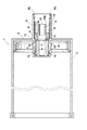
図1および図2は、本発明による孔版印刷用インキ容器の一実施の形態を、使用途中状態および使用完了状態についてそれぞれ示す断面図、図3は、小径中栓が装着される以前のインキ容器本体のインキ充填口近傍の断面図である。 1 and 2 are cross-sectional views showing an embodiment of an ink container for stencil printing according to the present invention in the middle of use and in a use completed state, respectively, and FIG. 3 is an ink container before a small-diameter inner plug is mounted. It is sectional drawing of the ink filling port vicinity of a main body.
インキ容器本体1は、一端を端壁4により閉塞されたシリンダ状の側壁3と、この側壁3に内接してインキ容器本体1の軸線方向に移動可能に設けられたピストンPとを備え、端壁4とピストンPとの間にインキ充填室5が画成されている。ピストンPの中心部には、このピストンPからインキ充填室5側とは反対側に窪んだコップ状の凹部8が同軸的に形成され、この凹部8内壁面には、周方向に連続した係止突条9が環状に形成されている。この係止突条9は、図1から明らかなように、インキ充填室5側に斜面を、インキ充填室5側とは反対側に、インキ容器本体1の軸線に対して略垂直な面を備え、フック状の断面形状を有している。
The ink container
また、図3に示すように、インキ容器本体1は、その端壁4にインキ充填口2と、このインキ充填口2を同軸的に取り囲むように端壁4から軸線方向外方に突出するガイド用円筒体6を備え、この円筒体6の内周面6aの内径は、インキ充填口2の内径D1よりも大きく形成され、これによって、端壁4のインキ充填口2の周縁には円環状の周縁部7が形成されている。また内周面6aの先端側に、外側に開くテーパー面6bが形成されている。
As shown in FIG. 3, the ink container
インキ容器本体1の上記インキ充填口2には、図4(a),(b),(c)にそれぞれ平面図、左半分を断面で示す正面図および底面図で示すような小径中栓10が取り付けられている。
The
中空の円筒状小径中栓10は、弾性を有する合成樹脂材料で一体に形成されており、その軸線方向に沿って中間に位置する第1部分10Aと、この第1部分10Aの一方に同軸的に連接された第2部分10Bと、第1部分10Aの他方に同軸的に連接された第3部分10Cとによって一体に構成されている。
The hollow cylindrical small-diameter
上記小径中栓10の第1部分10Aは、インキ容器本体1のインキ充填口2の内径D1よりも大径に形成されて、ガイド用円筒体6の内周面6aに嵌合されている。この第1部分10Aの外周部は、第2部分10B側から切り込まれた環状溝Gによって同軸的な弾性環状部11を形成しており、第1部分10Aが円筒体6の内周面6aに嵌合される以前は、上記弾性環状部11は、その第2部分10B側の自由端が若干外方に開いた状態で、円筒体6の内周面6aの内径よりも大径をなしている。そして、図1および図2に示すように、第1部分10Aが円筒体6の内周面6aに嵌合されると、弾性環状部11が縮径されて、円筒体6の内周面6aに液密的に圧接されるようになっている。
The
小径中栓10の第2部分10Bは、第1部分10Aよりも小径の外径と、インキ充填口2の内径D1よりも小径(1/2程度)の内径D2とを備えた円筒体からなり、その先端にインキ抽出口12が開口しているとともに、その外周に、図5に示すようなインキ吸引ポンプ20の吸引ノズル21が嵌着されるように構成されている。
The
小径中栓10の第3部分10Cは、フック15のような抜止め手段を備え、インキ容器本体1のインキ充填口2に打込み方式で嵌着され、インキ充填室5内に突出するようになっている。この第3部分10Cは、後述するフック15,16を除いてインキ充填口2の内径D1よりも僅かに小径に形成され、インキ充填口2よりも大径の第1部分10Aとの境界部が段部13を形成し、この段部13がインキ充填口2の周縁部7に当接するようになっている。
The
この第3部分10Cの周壁には、その先端側から軸線方向に略根元まで延びる、すなわち先端側から第1部分10Aの近傍まで延びる4本のスリットSが略等角度間隔に形成されており、これによって4個の弾性脚片14が形成されている。各弾性脚片14の外面には、上記抜止め手段を構成するフック15が上記段部13から所定の間隔をおいた位置に形成されて、これらフック15と段部13との間にインキ充填口2の周縁部7と係合する溝が形成されている。また、各弾性脚片14の先端部の外面にもフック16が設けられ、これらフック15,16は、ともに弾性脚片14の先端側に向かって縮径する斜面を備え、両フック15,16の第1部分10A側の面は、小径中栓10の軸線に略垂直となっている。
On the peripheral wall of the
図5は、図1に示す孔版印刷用インキ容器に孔版印刷用インキを充填した孔版印刷用インキ充填済容器をインキ吸引ポンプ20に設置した状態の断面図を示すものである。
FIG. 5 shows a cross-sectional view of the
図5に示す孔版印刷用インキ充填済容器は、インキ容器本体1のインキ充填口2からインキ容器本体1の内部に孔版印刷用インキを充填した後、上記のように構成された小径中栓10を、孔版印刷用インキが充填されたインキ充填済容器本体1Aのインキ充填口2の内側に取り付けて製造されたものである。
The ink-filled container for stencil printing shown in FIG. 5 has a small-
上記小径中栓10の取り付けの際には、まず、上記小径中栓10の第1部分10Aの段部13がインキ充填済容器本体1Aのインキ充填口2の周縁部7に当接するまで、その第3部分10Cがインキ充填口2に打ち込まれる。その際に、第3部分10Cが備えている弾性脚片14の外周面に突設されているフック15,16の斜面がインキ充填口2の周縁部7に当接するが、第3部分10Cには、その先端から、中間のフック15を越えて第1部分10Aの近傍まで延びる4本のスリットSが形成されていることにより、弾性脚片14は容易に撓んでフック15,16の通過が許容され、フック15と段部13との間の溝にインキ充填口2の周縁部7が係合する。また、小径中栓10の第1部分10Aは、円筒体6の内周面6aに嵌合されることにより、弾性環状部11が縮径されて、ガイド用円筒体6の内周面6aに液密的に圧接される。
When mounting the small-diameter
インキ吸引ポンプ20は、インキ容器本体1の円筒体6の内周面6aと、小径中栓10のインキ抽出口12を備えた第2部分10Bの外周面との間に挿入可能な外径と内径とを有する吸引ノズル21を備えており、円筒体6の内周のテーパー面6bにガイドされて小径中栓10の第2部分10Bの外周に嵌合するように構成され、かつ吸引ノズル21の内周面にシール用Oリング22が設けられていることにより、吸引ノズル21が第2部分10Bに対し液密的に嵌着されるようになっている。
The
上記小径中栓10がインキ充填口2に取り付けられるのに先立って、インキ充填口2からインキ充填室5内に充填されたインキは、図5に示す状態において、インキ吸引ポンプ20によって吸引されるが、この吸引に伴って、ピストンPがインキ容器本体1の端壁4に向かって側壁3に沿って移動する。
Prior to the small-
そして、このピストンPの移動に伴って、小径中栓10の第3部分10CがピストンPの凹部8内に挿入され、ピストンPが端壁4に至近距離まで接近した時点で、小径中栓10の第3部分10Cのフック16の斜面に、ピストンPの凹部8内の係止突条9の斜面が係合するが、フック16が弾性脚片14上に形成されていることにより、弾性脚片14が撓んでピストンPの移動が許容され、図2に示すように、ピストンPが端壁4に接触した時点で、すなわち、インキ充填室5内のインキがほとんど空になった時点で、小径中栓10の第3部分10Cの先端のフック16が、ピストンPの凹部8内の係止突条9と逆止係合して、ピストンPを捕捉する。
With the movement of the piston P, the
次に、インキ容器の交換のため、小径中栓10の第2部分10Bが吸引ノズル21から引き抜かれるが、そのときの吸引ノズル21によって小径中栓10が図5の右方向に強く引かれるため、インキ充填口2に対する第3部分10Cの、上記引張力に耐え得る嵌合強度が、少なくとも50Nとなるように、小径中栓10の材質およびフック15の高さを設定し、小径中栓10が吸引ノズル21に連れてインキ容器本体1Aから引き抜かれないようにした。また、このとき上記設定は、フック16がピストンPを捕捉してないものと仮定して行われた。
Next, in order to replace the ink container, the
引張力の測定方法は下記の通りである。すなわち、小径中栓10の第2部分10Bの外径をφ8.0mm、インキ吸引ノズル21内にあるOリング22の内径をφ7.8mmとして、インキ容器を図5に示すようにセットし、インキ容器を吸引ノズル21から引き抜くときに小径中栓10にかかる荷重(引張力)を、容器後端に接続したプッシュプルスケール(今田製作所製MAX50kgf)を用いて測定した。なお、この測定は、インキが充填されていないインキ容器を用いて行なった。この測定の結果、引張力は15N〜35Nであった。
The measuring method of tensile force is as follows. That is, the outer diameter of the
以上の結果より、上記のような引張力に耐えるためには、インキ充填口2に対する第3部分10Cの嵌合強度を50N以上とすることが好ましいことが判明した。
From the above results, it has been found that in order to withstand the tensile force as described above, the fitting strength of the
嵌合強度の測定は、オートグラフ(SHIMADZU製AGS−500D)を用い、図1のようにインキ容器本体1に取り付けられた小径中栓10の内側の面F(インキ容器本体1の軸線と垂直な面)に荷重を加え、インキ容器本体1から小径中栓10を外す際に必要な荷重を測定した。測定速度は、1000mm/分とした。
The fitting strength was measured using an autograph (AGS-500D manufactured by SHIMADZU), and the inner surface F of the small-
また、小径中栓10の第2部分10Bの内径D2は、インキ容器本体1の交換時に、少なくとも20秒間はインキ抽出口12からのインキ垂れが生じないように、インキの粘度に応じて大きさを設定した。
Further, the inner diameter D2 of the
ところで、容器内部のインキが垂れるおそれがあるのは、新しいインキ容器のキャップを外してから容器を印刷装置に取り付けるまでの時間で、長くとも10秒程度であると考えられる。したがって、不慣れなユーザーを想定して20秒間を基準としたのである。この場合、インキが充填された容器のインキ抽出口12が下になるようにし、この状態で20秒間静置し、インキの垂れの状態を評価して、第2部分10Bの内径D2を設定した。
By the way, it is considered that the ink inside the container may drip is the time from removing the cap of the new ink container to attaching the container to the printing apparatus, which is about 10 seconds at the longest. Therefore, 20 seconds was used as a reference for an unfamiliar user. In this case, the
以上の説明から明らかなように、本実施の形態によるインキ容器は、一端を端壁4により閉塞されたインキ容器本体1の端壁4に設けられたインキ充填口2に、このインキ充填口2よりも小径のインキ抽出口12を先端に備えてインキ吸引ノズル21が液密的に嵌着される円筒状の第2部分10Bを備えた小径中栓10が取り付けられているので、インキ容器本体1に対する高いインキ充填効率を確保しながら、孔版印刷装置への取付け時や孔版印刷装置からの取外し時において、インキ抽出口12からのインキ垂れを防止することができる。そしてインキの粘度に応じた内径のインキ抽出口12を備えた小径中栓10を選択することにより、粘度の低いインキを収容した場合であっても、インキ抽出口12からのインキ垂れを防止することができる。
As is clear from the above description, the ink container according to the present embodiment is connected to the
また、本実施の形態における小径中栓10は、小径中栓10に求められるシール性(液密性)の確保と、抜け防止機能とを、第1部分10Aと第3部分10Cとにそれぞれ分担させることによってシール性を確保し、かつ高い嵌合強度を維持しつつ、小径中栓10をインキ充填口2に嵌着するときの負荷を低減することができる。
Further, the small-diameter
すなわち、第1部分10Aの外周部が、円筒体6の内周面6aに嵌合される以前は内周面6aの内径よりも大径をなす弾性環状部11を形成していることにより、小径中栓10が膨潤したり膨張したりしても常に安定したシール性を確保することができ、しかもこの弾性環状部11は極めて撓みやすい構成を有するために、小径中栓10をインキ充填口2に嵌着するときの負荷にはならない。
That is, by forming the elastic
また、第3部分10Cには、その先端から、フック15を越えて第1部分10Aの近傍まで延びる4本のスリットSが形成されていて、脚片14が撓みやすくなっているため、小径中栓10を打込み方式でインキ充填口2に嵌着するときに、フック16,15がインキ充填口2の縁部7に当接すると、脚片14が容易に撓んでフック16,15の通過が許容される。したがって、吸引ノズル21を第2部分10Bから抜き取るときの引張力に耐え得る高い嵌合強度が得られるようにフック15を十分に高くすることを可能にしながら、小径中栓10をインキ容器本体のインキ充填口2に嵌着するときの負荷を低減することができる。
Further, the
図6(a),(b),(c)は、本発明による小径中栓の別の実施の形態を示す断面図である。図6(a),(b),(c)に示す小径中栓30,40,50も、上述した小径中栓10と同様に、それぞれ弾性を有する環状部31,41、51を備えた第1部分30A,40A,50Aと、それぞれインキ抽出口32,42,52を備えた円筒状の第2部分30B,40B,50Bと、それぞれフック35,45,55およびスリットSを備えた第3部分30C,40C,50Cとによって構成されているが、いずれも上記ピストンと係合するフックは備えていない。そして、図6(a),(b)に示す小径中栓30,40は、環状部31,41が小径中栓10とは異なる形状で形成されている。また、図6(c)に示す小径中栓50は、小径中栓10に比べると弾性脚片55が短めに形成されているものであるが、その他の構成は小径中栓10と概略同様であり、小径中栓10と同様の効果を有するものである。
6 (a), 6 (b), and 6 (c) are cross-sectional views showing another embodiment of the small-diameter medium plug according to the present invention. 6 (a), 6 (b), and 6 (c), the small-diameter inner plugs 30, 40, and 50 are also provided with
また、第3部分30C,40C、50Cのフック35,45,55よりも下方に短い筒状部分を設けることにより、小径中栓30,40,50をインキ容器本体1に挿入する際の安定性を高めることができる。
Further, by providing a short cylindrical portion below the
なお、上述した実施の形態においては、小径中栓10,30,40,50全体が弾性を有する合成樹脂材料で形成されているが、第1部分10A,30A,40A,50Aのみが弾性部材で形成されたものであってもよい。
In the above-described embodiment, the entire small-diameter
1 インキ容器本体
1A インキ充填済容器本体
2 インキ充填口
3 側壁
4 端壁
5 インキ充填室
6 ガイド用円筒体
7 周縁部
8 ピストンの凹部
9 係止突条
10,30,40,50 小径中栓
10A,30A,40A,50A 第1部分
10B,30B,40B,50B 第2部分
10C,30C,40C,50C 第3部分
11,31,41,51 弾性環状部
12,32,42,52 インキ抽出口
13 段部
14 弾性脚片
15,16,35,45,55 フック
20 インキ吸引ポンプ
21 吸引ノズル
22 Oリング
P ピストン
S スリット
DESCRIPTION OF
Claims (9)
前記インキ容器本体が、前記インキ充填口を囲んで前記端壁から外方に突出するガイド用円筒体を備え、
前記小径中栓が、該小径中栓の外周面に一体に設けられた弾性環状部を備え、
該弾性環状部の自由端外周面が、縮径されて前記ガイド用円筒体の内周面に液密的に圧接されるものであることを特徴とする孔版印刷用インキ容器。 An ink filling port provided in the end wall of the ink container main body, at least one end of which is closed by the end wall, is inserted inside the ink extraction port having a smaller diameter than the ink filling port and the suction nozzle of the ink suction pump. And a small-diameter medium stopper provided with means for allowing the suction nozzle of the ink suction pump to access the ink extraction port,
The ink container body includes a guide cylinder that protrudes outward from the end wall surrounding the ink filling port,
The small-diameter inner plug includes an elastic annular portion integrally provided on the outer peripheral surface of the small-diameter inner plug,
An ink container for stencil printing, wherein an outer peripheral surface of a free end of the elastic annular portion is reduced in diameter and is liquid-tightly pressed against an inner peripheral surface of the guide cylinder.
前記端壁に設けられたインキ充填口と、
該インキ充填口に取り付けられた、インキ充填口よりも小径のインキ抽出口とインキ吸引ポンプの吸引ノズルの内側に挿入されるとともに、インキ吸引ポンプの吸引ノズルを前記インキ抽出口にアクセスさせる手段とを有する小径中栓と、
前記インキ容器本体内に充填された孔版印刷用インキとを備え、
前記インキ容器本体が、前記インキ充填口を囲んで前記端壁から外方に突出するガイド用円筒体を備え、
前記小径中栓が、該小径中栓の外周面に一体に設けられた弾性環状部を備え、
該弾性環状部の自由端外周面が、縮径されて前記ガイド用円筒体の内周面に液密的に圧接されるものであることを特徴とする孔版印刷用インキ充填済容器。 An ink container body having at least one end closed by an end wall;
An ink filling port provided in the end wall;
A means attached to the ink filling port, inserted into the ink extraction port having a smaller diameter than the ink filling port, and the suction nozzle of the ink suction pump, and means for allowing the suction nozzle of the ink suction pump to access the ink extraction port; A small-diameter inner plug having
Comprising stencil printing ink filled in the ink container body,
The ink container main body includes a guide cylinder that protrudes outward from the end wall surrounding the ink filling port,
The small-diameter inner plug includes an elastic annular portion integrally provided on the outer peripheral surface of the small-diameter inner plug,
An ink-filled container for stencil printing, wherein the outer peripheral surface of the free end of the elastic annular portion is reduced in diameter and is liquid-tightly pressed against the inner peripheral surface of the guide cylinder.
前記インキ容器本体のインキ充填口よりも大径の外径を備えた円筒状の第1部分と、
前記インキ抽出口を先端に備えて前記第1部分の一方に同軸的に一体に連接され、インキ吸引ポンプの吸引ノズルの内側に挿入されるとともに、インキ吸引ポンプの吸引ノズルを抜差し的に嵌合させる、前記第1部分よりも小径の円筒状の第2部分と、
前記吸引ノズルが前記第2部分から引き抜かれるときの引張力に耐え得る嵌合強度をもたらす抜止め手段を備えて前記第1部分の他方に同軸的に一体に連接され、前記インキ充填口に打込み方式で嵌着される円筒状の第3部分と、
を備え、
前記インキ容器本体が、前記インキ充填口を囲んで前記端壁から外方に突出するガイド用円筒体を備え、
該ガイド用円筒体の内側に前記小径中栓の第1部分が同軸的に配設されるとともに、該第1部分の外周部が、縮径されて前記ガイド用円筒体の内周面に液密的に圧接される自由端外周面を有する弾性環状部を形成していることを特徴とする小径中栓。 An ink extraction port having a diameter smaller than that of the ink filling port formed in the end wall of the ink container main body closed at least at one end by the end wall is configured to be fitted into the ink filling port by a driving method,
A cylindrical first portion having an outer diameter larger than the ink filling port of the ink container body;
The ink extraction port is provided at the front end and is coaxially connected integrally to one of the first parts and inserted inside the suction nozzle of the ink suction pump, and the suction nozzle of the ink suction pump is removably fitted. A cylindrical second portion having a smaller diameter than the first portion;
The suction nozzle is provided integrally with the other of the first portions, and is driven into the ink filling port, with a retaining means for providing a fitting strength capable of withstanding a tensile force when the suction nozzle is pulled out from the second portion. A cylindrical third part fitted in a manner;
With
The ink container body includes a guide cylinder that protrudes outward from the end wall surrounding the ink filling port,
The first portion of the small-diameter inner plug is coaxially disposed inside the guide cylindrical body, and the outer peripheral portion of the first portion is reduced in diameter so that the liquid is applied to the inner peripheral surface of the guide cylindrical body. A small-diameter inner plug characterized by forming an elastic annular portion having an outer peripheral surface of a free end that is in close pressure contact.
Priority Applications (7)
| Application Number | Priority Date | Filing Date | Title |
|---|---|---|---|
| JP2003355329A JP4536352B2 (en) | 2003-01-14 | 2003-10-15 | Ink container for stencil printing, ink-filled container for stencil printing, manufacturing method thereof, and small-diameter inner plug |
| US10/754,707 US7040223B2 (en) | 2003-01-14 | 2004-01-12 | Stencil printing ink container, stencil printing ink cartridge, method of manufacturing the ink cartridge, and inner plug for the ink container |
| EP04000461A EP1439075A3 (en) | 2003-01-14 | 2004-01-12 | Stencil printing ink container, stencil printing ink cartridge, method of manufacturing the ink cartridge, and inner plug for the ink container |
| MYPI20040078A MY142604A (en) | 2003-01-14 | 2004-01-13 | Stencil printing ink container, stencil printing ink cartridge, method of manufacturing the ink cartridge, and inner plug for the ink container |
| CNB200410001547XA CN1294010C (en) | 2003-01-14 | 2004-01-13 | Stencilization ink container, ink cartridge, method of manufacturing ink cartridge and inserter |
| KR1020040002145A KR100576192B1 (en) | 2003-01-14 | 2004-01-13 | Stencil printing ink container, stencil printing ink cartridge, method of manufacturing the ink cartridge, and inner plug for the ink container |
| TW093100899A TWI232181B (en) | 2003-01-14 | 2004-01-14 | Stencil printing ink container, stencil printing ink cartridge, method of manufacturing the ink cartridge, and inner plug for the ink container |
Applications Claiming Priority (2)
| Application Number | Priority Date | Filing Date | Title |
|---|---|---|---|
| JP2003005895 | 2003-01-14 | ||
| JP2003355329A JP4536352B2 (en) | 2003-01-14 | 2003-10-15 | Ink container for stencil printing, ink-filled container for stencil printing, manufacturing method thereof, and small-diameter inner plug |
Publications (2)
| Publication Number | Publication Date |
|---|---|
| JP2004237722A JP2004237722A (en) | 2004-08-26 |
| JP4536352B2 true JP4536352B2 (en) | 2010-09-01 |
Family
ID=32599310
Family Applications (1)
| Application Number | Title | Priority Date | Filing Date |
|---|---|---|---|
| JP2003355329A Expired - Lifetime JP4536352B2 (en) | 2003-01-14 | 2003-10-15 | Ink container for stencil printing, ink-filled container for stencil printing, manufacturing method thereof, and small-diameter inner plug |
Country Status (7)
| Country | Link |
|---|---|
| US (1) | US7040223B2 (en) |
| EP (1) | EP1439075A3 (en) |
| JP (1) | JP4536352B2 (en) |
| KR (1) | KR100576192B1 (en) |
| CN (1) | CN1294010C (en) |
| MY (1) | MY142604A (en) |
| TW (1) | TWI232181B (en) |
Families Citing this family (10)
| Publication number | Priority date | Publication date | Assignee | Title |
|---|---|---|---|---|
| NL2000634C2 (en) * | 2007-05-07 | 2008-11-10 | Bema Kunststoffen B V | Container and system for storing a liquid. |
| US20100196556A1 (en) * | 2009-02-05 | 2010-08-05 | James Wheeler | Container system |
| US8668119B2 (en) * | 2009-09-03 | 2014-03-11 | James Wheeler | Container for viscous comestibles |
| JP6604021B2 (en) | 2015-04-16 | 2019-11-13 | セイコーエプソン株式会社 | Ink supply system |
| JP2016203991A (en) | 2015-04-16 | 2016-12-08 | セイコーエプソン株式会社 | Liquid container |
| CN109414927B (en) * | 2016-07-12 | 2020-12-22 | 惠普发展公司,有限责任合伙企业 | Ink pumping |
| CN108944067B (en) * | 2018-07-16 | 2023-11-03 | 苏州锦新纳米科技有限公司 | Printing device applied to drying agent box in medicine bottle |
| CN210148924U (en) | 2019-01-04 | 2020-03-17 | 伊利诺斯工具制品有限公司 | Vacuum wiper and stencil printer having the same |
| CN110562596A (en) * | 2019-09-21 | 2019-12-13 | 黑龙江鸿葵科技有限公司 | Container for preventing powder particles in container from being exchanged |
| CN112297620A (en) * | 2020-10-30 | 2021-02-02 | 熊婷婷 | Printing ink box convenient to change |
Citations (7)
| Publication number | Priority date | Publication date | Assignee | Title |
|---|---|---|---|---|
| JPS623438U (en) * | 1985-06-21 | 1987-01-10 | ||
| JPS62193973A (en) * | 1985-09-30 | 1987-08-26 | 株式会社リコー | Boxed bag vessel |
| JPS62146798U (en) * | 1986-03-08 | 1987-09-16 | ||
| JPH0266471U (en) * | 1988-11-04 | 1990-05-18 | ||
| JPH0680170A (en) * | 1992-07-16 | 1994-03-22 | Riso Kagaku Corp | Refilling-preventing container |
| JP2000318288A (en) * | 1999-05-10 | 2000-11-21 | Tohoku Ricoh Co Ltd | Ink container |
| JP2001347744A (en) * | 2000-06-07 | 2001-12-18 | Riso Kagaku Corp | Ink bottle installing device |
Family Cites Families (6)
| Publication number | Priority date | Publication date | Assignee | Title |
|---|---|---|---|---|
| DE69305268T2 (en) * | 1992-07-16 | 1997-05-22 | Riso Kagaku Corp | Containers with means for preventing refilling |
| JP4302227B2 (en) | 1999-03-24 | 2009-07-22 | 東北リコー株式会社 | Ink container mounting device |
| JP3746177B2 (en) * | 1999-12-15 | 2006-02-15 | 理想科学工業株式会社 | Variable volume container |
| US6192797B1 (en) * | 1999-12-23 | 2001-02-27 | Sonoco Development, Inc. | Ink cartridge for automated dispensing systems |
| JP4730798B2 (en) | 2001-05-17 | 2011-07-20 | 東北リコー株式会社 | Outlet device for back-in box and back-in box |
| JP4260415B2 (en) | 2002-04-19 | 2009-04-30 | 株式会社ルネサステクノロジ | Semiconductor integrated circuit device and manufacturing method thereof |
-
2003
- 2003-10-15 JP JP2003355329A patent/JP4536352B2/en not_active Expired - Lifetime
-
2004
- 2004-01-12 US US10/754,707 patent/US7040223B2/en not_active Expired - Lifetime
- 2004-01-12 EP EP04000461A patent/EP1439075A3/en not_active Withdrawn
- 2004-01-13 KR KR1020040002145A patent/KR100576192B1/en active IP Right Grant
- 2004-01-13 CN CNB200410001547XA patent/CN1294010C/en not_active Expired - Lifetime
- 2004-01-13 MY MYPI20040078A patent/MY142604A/en unknown
- 2004-01-14 TW TW093100899A patent/TWI232181B/en not_active IP Right Cessation
Patent Citations (7)
| Publication number | Priority date | Publication date | Assignee | Title |
|---|---|---|---|---|
| JPS623438U (en) * | 1985-06-21 | 1987-01-10 | ||
| JPS62193973A (en) * | 1985-09-30 | 1987-08-26 | 株式会社リコー | Boxed bag vessel |
| JPS62146798U (en) * | 1986-03-08 | 1987-09-16 | ||
| JPH0266471U (en) * | 1988-11-04 | 1990-05-18 | ||
| JPH0680170A (en) * | 1992-07-16 | 1994-03-22 | Riso Kagaku Corp | Refilling-preventing container |
| JP2000318288A (en) * | 1999-05-10 | 2000-11-21 | Tohoku Ricoh Co Ltd | Ink container |
| JP2001347744A (en) * | 2000-06-07 | 2001-12-18 | Riso Kagaku Corp | Ink bottle installing device |
Also Published As
| Publication number | Publication date |
|---|---|
| KR20040066716A (en) | 2004-07-27 |
| CN1517208A (en) | 2004-08-04 |
| EP1439075A3 (en) | 2008-07-30 |
| TW200426044A (en) | 2004-12-01 |
| US20040139868A1 (en) | 2004-07-22 |
| TWI232181B (en) | 2005-05-11 |
| US7040223B2 (en) | 2006-05-09 |
| CN1294010C (en) | 2007-01-10 |
| KR100576192B1 (en) | 2006-05-03 |
| JP2004237722A (en) | 2004-08-26 |
| MY142604A (en) | 2010-12-15 |
| EP1439075A2 (en) | 2004-07-21 |
Similar Documents
| Publication | Publication Date | Title |
|---|---|---|
| JP4536352B2 (en) | Ink container for stencil printing, ink-filled container for stencil printing, manufacturing method thereof, and small-diameter inner plug | |
| EP0633137B1 (en) | Refill method for ink-jet print cartridge | |
| US5917523A (en) | Refill method for ink-jet print cartridge | |
| US5515663A (en) | Method of refilling ink-jet printer cartridges | |
| US7735983B2 (en) | Ink jet ink cartridge with vented wick | |
| HUP0204548A2 (en) | Ink reservoir for an inkjet printer | |
| TW201206715A (en) | Printing device fluid reservoir with gripping features | |
| US6971740B2 (en) | Ink cartridge refill system and method of use | |
| US2599561A (en) | Apparatus for inking ribbons | |
| EP0771663A2 (en) | Method and apparatus for refilling ink jet unit printer cartridges | |
| US6663234B2 (en) | Ink cartridge providing improved ink supply | |
| US7303267B2 (en) | Actuator for automatic ink refill system | |
| TW470707B (en) | Method for supplementing ink and ink supplement jig used for execution of the method | |
| JP4248914B2 (en) | Ink container for stencil printing | |
| JP4220065B2 (en) | Ink container | |
| WO2007086848A1 (en) | Apparatus for refilling ink cartridges | |
| JP4091245B2 (en) | Inkjet recording device | |
| JP3237109U (en) | Direct liquid ink cartridge | |
| JP3007905U (en) | Stamp | |
| US20020015607A1 (en) | Ink cartridge | |
| EP1369245B1 (en) | Ink supply system and ink supply method for stencil printer and ink container | |
| JP3011125U (en) | Stamp | |
| JP2020142456A (en) | Direct liquid type ink cartridge | |
| AU2011101196A4 (en) | Improved priming device for inkjet printer ink supply system | |
| JP3190830U (en) | ink cartridge |
Legal Events
| Date | Code | Title | Description |
|---|---|---|---|
| A621 | Written request for application examination |
Free format text: JAPANESE INTERMEDIATE CODE: A621 Effective date: 20060727 |
|
| A977 | Report on retrieval |
Free format text: JAPANESE INTERMEDIATE CODE: A971007 Effective date: 20090714 |
|
| A131 | Notification of reasons for refusal |
Free format text: JAPANESE INTERMEDIATE CODE: A131 Effective date: 20090728 |
|
| A521 | Request for written amendment filed |
Free format text: JAPANESE INTERMEDIATE CODE: A523 Effective date: 20090918 |
|
| A131 | Notification of reasons for refusal |
Free format text: JAPANESE INTERMEDIATE CODE: A131 Effective date: 20091027 |
|
| A521 | Request for written amendment filed |
Free format text: JAPANESE INTERMEDIATE CODE: A523 Effective date: 20091228 |
|
| A131 | Notification of reasons for refusal |
Free format text: JAPANESE INTERMEDIATE CODE: A131 Effective date: 20100202 |
|
| A521 | Request for written amendment filed |
Free format text: JAPANESE INTERMEDIATE CODE: A523 Effective date: 20100319 |
|
| TRDD | Decision of grant or rejection written | ||
| A01 | Written decision to grant a patent or to grant a registration (utility model) |
Free format text: JAPANESE INTERMEDIATE CODE: A01 Effective date: 20100601 |
|
| A01 | Written decision to grant a patent or to grant a registration (utility model) |
Free format text: JAPANESE INTERMEDIATE CODE: A01 |
|
| A61 | First payment of annual fees (during grant procedure) |
Free format text: JAPANESE INTERMEDIATE CODE: A61 Effective date: 20100616 |
|
| FPAY | Renewal fee payment (event date is renewal date of database) |
Free format text: PAYMENT UNTIL: 20130625 Year of fee payment: 3 |
|
| R150 | Certificate of patent or registration of utility model |
Free format text: JAPANESE INTERMEDIATE CODE: R150 Ref document number: 4536352 Country of ref document: JP Free format text: JAPANESE INTERMEDIATE CODE: R150 |
|
| R250 | Receipt of annual fees |
Free format text: JAPANESE INTERMEDIATE CODE: R250 |
|
| R250 | Receipt of annual fees |
Free format text: JAPANESE INTERMEDIATE CODE: R250 |
|
| R250 | Receipt of annual fees |
Free format text: JAPANESE INTERMEDIATE CODE: R250 |
|
| R250 | Receipt of annual fees |
Free format text: JAPANESE INTERMEDIATE CODE: R250 |
|
| R250 | Receipt of annual fees |
Free format text: JAPANESE INTERMEDIATE CODE: R250 |
|
| R250 | Receipt of annual fees |
Free format text: JAPANESE INTERMEDIATE CODE: R250 |
|
| R250 | Receipt of annual fees |
Free format text: JAPANESE INTERMEDIATE CODE: R250 |
|
| R250 | Receipt of annual fees |
Free format text: JAPANESE INTERMEDIATE CODE: R250 |
|
| R250 | Receipt of annual fees |
Free format text: JAPANESE INTERMEDIATE CODE: R250 |
|
| R250 | Receipt of annual fees |
Free format text: JAPANESE INTERMEDIATE CODE: R250 |
|
| R250 | Receipt of annual fees |
Free format text: JAPANESE INTERMEDIATE CODE: R250 |
|
| EXPY | Cancellation because of completion of term |