JP4532979B2 - Image forming apparatus and control method thereof - Google Patents
Image forming apparatus and control method thereof Download PDFInfo
- Publication number
- JP4532979B2 JP4532979B2 JP2004139091A JP2004139091A JP4532979B2 JP 4532979 B2 JP4532979 B2 JP 4532979B2 JP 2004139091 A JP2004139091 A JP 2004139091A JP 2004139091 A JP2004139091 A JP 2004139091A JP 4532979 B2 JP4532979 B2 JP 4532979B2
- Authority
- JP
- Japan
- Prior art keywords
- gradation pattern
- pattern
- color
- recording medium
- gradation
- Prior art date
- Legal status (The legal status is an assumption and is not a legal conclusion. Google has not performed a legal analysis and makes no representation as to the accuracy of the status listed.)
- Expired - Fee Related
Links
Images


Description
本発明はカラー画像形成装置及びその制御方法に関するものである。 The present invention relates to a color image forming apparatus and a control method thereof.
近年、カラープリンタ、カラー複写機等の電子写真方式やインクジェット方式等を採用したカラー画像形成装置では写真に匹敵する画質が可能となってきており、今後も益々高画質化が求められている。 In recent years, color image forming apparatuses employing an electrophotographic system such as a color printer and a color copying machine, an inkjet system, and the like have become possible to achieve an image quality comparable to that of a photograph.
ところが、カラー画像形成装置は、環境の変化や長時間の使用による装置各部の状態変動があると、得られる画像の色も変動する。特に電子写真方式のカラー画像形成装置の場合、わずかな環境変動でも色の変動が生じ、カラーバランスを崩す恐れがある。このため、色及び色の階調性を安定して再現するための手段を有している。例えば、各色のトナーに対して、絶対湿度に応じた数種類の露光量や現像バイアスなどのプロセス条件、画像データ変換テーブルなどの階調補正手段をもち、温湿度センサによって測定された絶対湿度に基づいて、その時のプロセス条件や階調補正の最適値を選択している。また、装置各部の変動が起こっても一定の色及び色の階調性が得られるように、各色のトナー単色で濃度検知用トナー像(パッチ)を中間転写体や感光体等の上に形成し、その未定着単色パッチの濃度を未定着トナー用濃度検知センサ(以下濃度センサとする)で検知し、その検知結果より露光量、現像バイアスなどのプロセス条件や画像データ変換テーブルなどの階調補正手段にフィードバックをかけて濃度制御を実施することで、安定した色及び色の階調性を得るように構成している。 However, in the color image forming apparatus, when there is a change in the state of each part of the apparatus due to a change in environment or long-term use, the color of the obtained image also changes. In particular, in the case of an electrophotographic color image forming apparatus, even a slight environmental change may cause a color change, which may cause a loss of color balance. For this reason, it has means for stably reproducing the color and the gradation of the color. For example, for each color toner, there are several kinds of exposure amount and development bias depending on the absolute humidity, development bias and other gradation correction means such as an image data conversion table, based on the absolute humidity measured by the temperature and humidity sensor Thus, the optimum process conditions and gradation correction values are selected. In addition, a density detection toner image (patch) is formed on an intermediate transfer member, a photosensitive member, or the like with a single color toner so that a constant color and gradation of color can be obtained even if fluctuations occur in each part of the apparatus. Then, the density of the unfixed single-color patch is detected by a density detection sensor for unfixed toner (hereinafter referred to as a density sensor). By providing feedback to the correction means and performing density control, a stable color and color gradation are obtained.
ただし、濃度センサを用いた濃度制御はパッチを中間転写体やドラム等の上に形成し検知するもので、その後に行われる記録媒体への転写及び定着による画像のカラーバランスの変化については制御していないのが現状である。ところが、記録媒体へのパッチの転写における転写効率や、定着による加熱及び加圧によっても濃度やカラーバランスが変化することがわかってきた。かかる点については、これまでの前記濃度センサを用いた濃度制御では対応できない。 However, density control using a density sensor detects patches by forming patches on an intermediate transfer member, drum, etc., and controls changes in image color balance due to subsequent transfer and fixing to a recording medium. The current situation is not. However, it has been found that the density and color balance also change depending on the transfer efficiency in transferring a patch to a recording medium, and heating and pressurization by fixing. Such a point cannot be dealt with by the conventional density control using the density sensor.
そこで記録媒体上にシアン(C)、マゼンダ(M)、イエロー(Y)、ブラック(K)の単色の階調トナー像や、C,M,Y混色のトナー像を形成し、定着後に記録媒体上のトナー像の濃度又は色度を検知するセンサ(以下カラーセンサという)を設置したカラー画像形成装置が提案されている(特許文献1)。 Therefore, cyan (C), magenta (M), yellow (Y), and black (K) single tone toner images and C, M, and Y mixed color toner images are formed on the recording medium, and the recording medium is fixed after fixing. There has been proposed a color image forming apparatus provided with a sensor (hereinafter referred to as a color sensor) for detecting the density or chromaticity of the upper toner image (Patent Document 1).
カラーセンサを設置したカラー画像形成装置では、検知した結果を画像形成部の露光量やプロセス条件、濃度−階調特性を補正するためのキャリブレーションテーブルなどへフィードバックすることで、記録媒体上に形成した最終出力画像の濃度制御又は色度制御を実施することができる。カラー画像形成装置の出力画像を外部の画像読取装置又は濃度計・色度計で検知し、同様の制御を実施することも可能であるが、カラー画像形成装置内で制御が完結する点で優れている。このカラーセンサは、例えば発光素子として赤(R)、緑(G)、青(B)等の発光スペクトルが異なる3種以上の光源を用いるか、又は発光素子は白色(W)を発光する光源を用いて、受光素子上にR、G、B等の分光透過率が異なる3種以上のフィルタを形成したもので構成することになる。このことによりRGB出力等の異なる3種以上の出力が得られる。 In a color image forming apparatus equipped with a color sensor, the detection result is fed back to a calibration table for correcting the exposure amount of the image forming unit, process conditions, density-gradation characteristics, etc., and formed on a recording medium. Thus, density control or chromaticity control of the final output image can be performed. Although it is possible to detect the output image of the color image forming apparatus with an external image reading device or a densitometer / colorimeter and implement the same control, it is excellent in that the control is completed within the color image forming apparatus. ing. This color sensor uses, for example, three or more light sources having different emission spectra such as red (R), green (G), and blue (B) as light emitting elements, or the light emitting element emits white light (W). Is used, and three or more types of filters having different spectral transmittances such as R, G, and B are formed on the light receiving element. As a result, three or more different outputs such as RGB output can be obtained.
インクジェット方式のカラー画像形成装置においても、インク吐出量の経時変化や環境差、インクカートリッジの個体差によりカラーバランスが変化し、濃度‐階調特性を一定に保てない。そこで、カラーセンサを設けることで記録媒体上のパッチの濃度又は色度を検知し、濃度制御又は色度制御を実施しているインクジェット方式のカラー画像形成装置もある。
カラーセンサを用いて濃度制御や色度制御を実施する場合、記録媒体上に数点の離散階調パッチを形成し、その離散パッチの各濃度や各色度を測定して補間することで画像形成装置の階調特性を求めていた。しかしながら、離散パッチでは階調特性の形を正確に求めることは困難で、微妙な色相変動を捉えきる事は非常に難しい。特に、ハイライト側に作成する最初のパッチよりもさらに淡い部分は“0”と、その最初のパッチの濃度から補間することしかできないため階調が出始める部分を正確に知ることができない。ハイライト側の階調特性が正確にわからないとグラデーションがかかっている画像などでは疑似輪郭ができたり、本来淡い部分が濃く出てしまったりと不自然なグラデーションになってしまう。また、パッチの画像データ値の選び方が常に適切でないと環境変動などで階調特性が大きく変化した場合に誤った階調特性を求めてしまうことがある。 When density control and chromaticity control are performed using a color sensor, image formation is performed by forming several discrete tone patches on a recording medium and measuring and interpolating each density and each chromaticity of the discrete patch. The tone characteristics of the device were sought. However, with a discrete patch, it is difficult to accurately determine the shape of the gradation characteristics, and it is very difficult to capture subtle hue fluctuations. In particular, the portion that is lighter than the first patch created on the highlight side is “0”, and since interpolation can only be performed from the density of the first patch, the portion where the gradation starts to appear cannot be accurately known. If the gradation characteristics on the highlight side are not accurately known, an image with gradation, such as a pseudo contour, or an originally faint part will appear dark will result in an unnatural gradation. Further, if the method of selecting the image data value of the patch is not always appropriate, an erroneous gradation characteristic may be obtained when the gradation characteristic changes greatly due to environmental fluctuations.
以上のような状況に鑑み、本発明は階調特性の形を正確に検知して常に高画質の画像を得ることができる技術を提供しようとするものである。 In view of the circumstances as described above, the present invention intends to provide a technique capable of accurately detecting the shape of gradation characteristics and always obtaining a high-quality image.
かかる課題を解決するため、例えば本発明の画像形成装置は以下の構成を備える。すなわち、
カラー画像を記録媒体上に形成する画像形成装置であって、
所定の指示が入力された場合、前記記録媒体上に、当該記録媒体の搬送方向に沿って連続的且つ一様に変化するパッチからなる階調パターンを定着して形成するパターン形成手段と、
複数のパッチを跨ぐスポット径の光を前記形成された前記階調パターンに照射して、その反射光に従って階調パターンの濃度或いは色を検知する検知手段と、
前記検知された濃度或いは色に基づいて印刷条件を設定する設定手段と、
前記記録媒体の搬送方向の記録可能サイズを検出する手段と、
検出された前記記録可能サイズと、前記連続的且つ一様に変化する階調パターンを記録する際に必要となる長さとを比較する比較手段と、を備え、
前記パターン形成手段は、前記比較手段の比較結果が前記記録可能サイズが前記階調パターンを記録する際に必要となる長さに満たないことを示す場合、前記記録可能サイズに従って前記階調パターンを複数に分割して、分割された階調パターンの分割部分に互いにオーバーラップする所定数の階調数のパッチを含むように階調パターンを形成し、複数の記録媒体上にそれぞれの分割した階調パターンを形成することを特徴とする。
また、他の発明である、画像形成装置は以下の構成を備える。すなわち、
カラー画像を記録媒体上に形成する画像形成装置であって、
所定の指示が入力された場合、前記記録媒体上に、当該記録媒体の搬送方向に沿って連続的且つ一様に変化するパッチからなる階調パターンを定着して形成するパターン形成手段と、
複数のパッチを跨ぐスポット径の光を前記形成された前記階調パターンに照射して、その反射光に従って階調パターンの濃度或いは色を検知する検知手段と、
前記検知された濃度或いは色に基づいて印刷条件を設定する設定手段と、
前記記録媒体のサイズを検出する手段と、を備え、
前記パターン形成手段は、前記検出により記録媒体の搬送方向の記録可能サイズが前記階調パターンを記録する際に必要となる長さに満たない場合、前記階調パターンを複数に分割して、分割された階調パターンの分割部分に互いにオーバーラップする所定数の階調数のパッチを含むように階調パターンを形成し、複数の記録媒体上にそれぞれの分割した階調パターンを形成することを特徴とする。
In order to solve this problem, for example, an image forming apparatus of the present invention has the following configuration. That is,
An image forming apparatus for forming a color image on a record medium,
A pattern forming unit that fixes and forms a gradation pattern consisting of patches that continuously and uniformly change along the conveyance direction of the recording medium on the recording medium when a predetermined instruction is input;
Detecting means for irradiating the formed gradation pattern with light having a spot diameter straddling a plurality of patches and detecting the density or color of the gradation pattern according to the reflected light ;
Setting means for setting printing conditions based on the detected density or color ;
Means for detecting a recordable size in the transport direction of the recording medium;
Comparing means for comparing the detected recordable size with the length required for recording the continuous and uniformly changing gradation pattern,
If the comparison result of the comparison means indicates that the recordable size is less than the length required for recording the gradation pattern, the pattern forming means determines the gradation pattern according to the recordable size. A gradation pattern is formed so as to include a predetermined number of patches that overlap each other in the divided portions of the divided gradation pattern, and each divided floor is formed on a plurality of recording media. A tone pattern is formed.
An image forming apparatus as another invention has the following configuration. That is,
An image forming apparatus for forming a color image on a recording medium,
A pattern forming unit that fixes and forms a gradation pattern consisting of patches that continuously and uniformly change along the conveyance direction of the recording medium on the recording medium when a predetermined instruction is input;
Detecting means for irradiating the formed gradation pattern with light having a spot diameter straddling a plurality of patches and detecting the density or color of the gradation pattern according to the reflected light;
Setting means for setting printing conditions based on the detected density or color;
Means for detecting the size of the recording medium,
The pattern forming means divides the gradation pattern into a plurality of divisions when the recordable size in the conveyance direction of the recording medium is less than the length required for recording the gradation pattern by the detection. Forming a gradation pattern to include a predetermined number of gradation patches that overlap each other in the divided portion of the gradation pattern, and forming each divided gradation pattern on a plurality of recording media. Features.
以上説明してきたように本発明によれば、中間調表現が可能な画像形成装置において連続階調パターンを実際に記録媒体上に出力して濃度又は色度を測定することになるので、階調特性の形を正確に知ることができ、適切な階調補正が可能となる。 As described above, according to the present invention, in an image forming apparatus capable of halftone expression, a continuous tone pattern is actually output onto a recording medium to measure density or chromaticity. The shape of the characteristic can be accurately known, and appropriate gradation correction can be performed.
以下添付図面を参照して、本発明を好適な実施形態に従って詳細に説明する。 Hereinafter, the present invention will be described in detail according to preferred embodiments with reference to the accompanying drawings.
<第1の実施形態>
図1は本第1の実施形態におけるカラー画像形成装置における画像形成に係る構成図である。図2はカラー画像形成装置の断面図である。この装置は、図示のように、電子写真方式のカラー画像形成装置の一例であるベルト状の中間転写体28を採用したタンデム方式のカラー画像形成装置である。図2を用いて、電子写真方式のカラー画像形成装置の動作を説明する。
<First Embodiment>
FIG. 1 is a configuration diagram relating to image formation in the color image forming apparatus according to the first embodiment. FIG. 2 is a cross-sectional view of the color image forming apparatus. As shown in the figure, this apparatus is a tandem color image forming apparatus employing a belt-like
帯電手段122として、Y(イエロー)、M(マゼンタ)、C(シアン)、K(ブラック)のステーション毎に、感光体22Y,22M,22C,22Kを帯電させるための4個の注入帯電器23Y、23M、23C、23Kを備える構成で、各注入帯電器にはスリーブ23YS、23MS、23CS、23KSを備えている。
As charging means 122, four
感光体22Y、22M、22C、22Kは、アルミシリンダの外周に有機光導伝層を塗布して構成し、図示しない駆動モータの駆動力が伝達されて回転するもので、駆動モータは感光体22Y、22M、22C、22Kを画像形成動作に応じて、図2においては反時計周り方向に回転させる。
The
露光手段123は、感光体22Y、22M、22C、22Kへスキャナ部24Y、24M、24C、24Kより露光光を照射し、感光体22Y、22M、22C、22Kの表面を選択的に露光することにより、静電潜像を形成するように構成している。
The exposure unit 123 irradiates the
現像手段124は、前記静電潜像を可視化するために、ステーション毎にY、M、C、Kの現像を行う4個の現像器26Y、26M、26C、26Kを備える構成で、各現像器には、スリーブ26YS、26MS、26CS、26KSが設けられている。なお、各々の現像器26は脱着が可能である。
The developing
転写手段125は、感光体22を現像して付着した単色トナーを、中間転写体28へ転写し、更に中間転写体28に転写された各色トナーを記録媒体11へ転写するものである。
The
そのため、中間転写体28を図2では時計周り方向に回転(搬送)させ、感光体22Y、22M、22C、22Kとその対向に位置する一次転写ローラ27Y、27M、27C、27Kの回転に伴って、単色トナー像を転写する。一次転写ローラ27に適当なバイアス電圧を印加すると共に感光体22の回転速度と中間転写体28の回転速度に差をつけることにより、効率良く単色トナー像を中間転写体28上に転写する。上記転写を一次転写という。
Therefore, the
更に転写手段125は、ステーション毎に単色トナー像を中間転写体28上に重ね合わせ、重ね合わせた多色トナー像を中間転写体28の回転に伴い二次転写ローラ29まで搬送し、さらに記録媒体11を給紙トレイ21a(もしくは手指しトレイ21b)から二次転写ローラ29へ狭持搬送し、記録媒体11に中間転写体28上の多色トナー像を転写する。この二次転写ローラ29に適当なバイアス電圧を印加し、静電的にトナー像を転写する。この転写を二次転写という。二次転写ローラ29は、記録媒体11上に多色トナー像を転写している間、29aの位置で記録媒体11に当接し、印字処理後は29bの位置に離間する。
Further, the transfer means 125 superimposes a single color toner image on the
以上の一次転写、二次転写を行うのが転写手段125である。 The transfer means 125 performs the above primary transfer and secondary transfer.
定着手段126は、記録媒体11に転写された多色トナー像を記録媒体11に溶融定着させるために、記録媒体11を加熱する定着ローラ32と記録媒体11を定着ローラ32に圧接させるための加圧ローラ33を備えている。定着ローラ32と加圧ローラ33は中空状に形成され、内部にそれぞれヒータ34、35が内蔵されている。定着装置31は、多色トナー像を保持した記録媒体11を定着ローラ32と加圧ローラ33により搬送するとともに、熱および圧力を加え、各色トナーを記録媒体11に定着させる。
The fixing
トナー定着後の記録媒体11は、その後、図示しない排出ローラによって図示しない排紙トレイに排出して画像形成動作を終了する。 Thereafter, the recording medium 11 after toner fixing is discharged to a discharge tray (not shown) by a discharge roller (not shown), and the image forming operation is completed.
クリーニング手段30は、中間転写体28上に張りついた残留トナーをクリーニングする。すなわち、中間転写体28上に形成された4色の多色トナー像を記録媒体11に転写した後の廃トナーは、クリーナ容器に蓄えられる。
The
濃度センサ41は、図2のカラー画像形成装置において中間転写体28へ向けて配置されており、中間転写体28の表面上に形成されたトナーパッチの濃度を測定する。この濃度センサ41の構成の一例を図3に示す。LEDなどの赤外発光素子51と、フォトダイオード、CdS等の受光素子52、受光データを処理する図示しないICなどとこれらを収容する図示しないホルダーで構成される。受光素子52aはトナーパッチからの乱反射光強度を検知し、受光素子52bはトナーパッチからの正反射光強度を検知する。正反射光強度と乱反射光強度の両方を検知することにより、高濃度から低濃度までのトナーパッチの濃度を検知することができる。なお、前記発光素子51と受光素子52の結合のために図示しないレンズなどの光学素子が用いられることもある。
The
カラーセンサ42は記録媒体搬送路の定着装置31より下流に位置し、記録媒体11の画像形成面へ向けて配置されており、記録媒体11上に形成された定着後の混色パッチの色を検知し、RGB値を出力する。カラーセンサ42の照射光の記録媒体11上におけるスポット径(直径)は5mm程度である。また、カラーセンサ42の対向にはパッチの絶対濃度及び絶対色度を得る為のセンサ出力校正用白色基準板43が設けられている。パッチ形成処理を行った際、記録媒体11がカラーセンサ42に到達する以前に、センサ出力校正用白色基準板43をカラーセンサ42で色を検出することで、基準となる絶対濃度及び絶対色度を検出することになる。なお、記録媒体の搬送する方向をy軸、それと直交する方向をx軸と定義したとき、濃度センサ41、とカラーセンサ42のx軸上の位置は同じであるものとする。
The
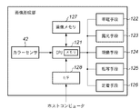
図4は、カラーセンサ42の周辺装置の構成を示す図である。カラーセンサ42は、発光素子101、受光素子102、A/Dコンバータ103、CPU121で構成される。発光素子101はカラーセンサの光源であり、測定対象物103へ光を入射する。すると、測定対象物の物体色に反射率が依存する乱反射光が反射する。その乱反射光は、光をアナログ電気信号へ変換する受光素子102へ入射する。さらにアナログ電気信号は、A/Dコンバータ104によりディジタル電気信号へと変換される。そして、ディジタル電気信号はCPU121に取り込まれ、一次変換又はルックアップテーブル等で処理されて、色度が出力される。
FIG. 4 is a diagram illustrating a configuration of a peripheral device of the
図5にカラーセンサ42の断面図を示す。カラーセンサ42は、発光素子101として白色LED53、受光素子102としてRGB等3色以上のオンチップフィルタ付き電荷蓄積型センサ54aを使用している。白色LED53を定着後のパッチが形成された記録媒体11に対して斜め45度より入射させ、0度方向への乱反射光強度をRGBオンチップフィルタ付き電荷蓄積型センサ54aにより検知する。RGBオンチップフィルタ付き電荷蓄積型センサ54aの受光部は、その受光面54bのようにRGB毎のフィルタを有し、それぞれの色成分毎に独立した受光素子で構成される。受光素子102は、フォトダイオードでも良い。RGBの3画素のセットが、複数セット並んでいるものでも良い。また、入射角が0度、反射角が45度の構成でも良い。更には、RGB等3色以上の発光するLEDとフィルタ無しセンサにより構成しても良い。
FIG. 5 shows a cross-sectional view of the
画像メモリ127はホストコンピュータからの印刷データを受信した際に、印刷出力用の各色成分毎のイメージデータを展開するためのものであり、インタフェース128はホストコンピュータと通信するためのものであり、印刷データ、並びに、色補正指示情報(印刷データと区別可能なコマンドで送られてくるものとする)を受信する。
The
一般の印刷データを受信した場合、CPU121は印刷データに基づくイメージの画像メモリ127への展開の処理、並びに、その際の印刷条件に従って帯電手段122乃至定着手段126、及び給紙機構を制御して印刷することになるが、その点は本願発明の主要部分ではないので省略し、印刷条件を決定するための制御処理について述べる。
When the general print data is received, the
この処理は、ホストコンピュータから所定の指示コマンドを受信した際、或いは、画像形成装置が有する操作パネル(不図示)上の所定のスイッチが操作された場合に実行されるものである。 This process is executed when a predetermined instruction command is received from the host computer or when a predetermined switch on an operation panel (not shown) of the image forming apparatus is operated.
本実施形態の特徴は、階調補正を実施する際、定着手段126の下流に位置するカラーセンサ42で検出するパッチとして連続階調パターンを用いる点にある。本実施形態では、各画素の色成分はそれぞれ8ビット(256階調)で表わされるものとする。
A feature of this embodiment is that a continuous tone pattern is used as a patch detected by the
8ビット画像信号の場合、00H〜FFH(Hは16進表示を意味する)の256レベルの画像データを発生可能なので、256レベルの画像データからなる連続階調パターンを使用する。本実施の形態で用いられるカラーセンサ42の照射光の記録媒体11上におけるスポット径は5mm程度に設定し、スポット内に3階調程度分の画像データが平均化されて安定に測定されるように、各データ分の大きさを幅7mm(記録紙搬送方向に直交する方向)、長さ1mm(記録紙搬送方向)とした。図6に連続階調パターンの模式図を示す。
In the case of an 8-bit image signal, image data of 256 levels from 00H to FFH (H means hexadecimal display) can be generated, and therefore a continuous tone pattern composed of image data of 256 levels is used. The spot diameter of the irradiation light of the
ホストコンピュータやユーザからの指示等の適当なタイミングをCPU121が検出すると、CPU121は各色毎の連続階調パターン測定シーケンスを開始する。カラーセンサ42によって連続階調パターンが測定されるに先立って、出力校正用の白色基準板43を測定してカラーセンサ42は校正される。CPU121は帯電手段122、露光手段123、現像手段124、転写手段125、定着手段126へ適切な信号を送り、記録媒体11上に連続階調パターンを形成し、連続階調パターンが形成された記録媒体11はカラーセンサ42によって連続階調パターンが測定できる位置へと搬送され、連続階調パターンの階調特性の形を正確に測定する。得られた階調特性の形も元にして、所望の階調特性となるように画像データ変換テーブルが書き換えられる。
When the
また、連続階調パターンに何らかの原因でムラが発生すると本来よりも薄い部分ができてしまい、濃度の測定値が部分的にばらつくことがある。そのような場合、まず測定データを5次程度の多項式で補間しデータのスムージングを行えばよい。測定データは256個あるため多少のばらつきがあっても正確に補間することができる。なお、多項式はその他の次数でもよいし、スプライン補間等を用いてもよい。このようにして、Y、M、C、Kの単色トナー像の階調特性はもちろん、R、G、B等の混色トナー像の階調特性の形を正確に測定して微妙な色変動も捉えることが可能となった。 In addition, if unevenness occurs in the continuous tone pattern for some reason, a thinner part than the original part is formed, and the density measurement value may partially vary. In such a case, the measured data may be first smoothed by interpolating the measurement data with a polynomial of the fifth order. Since there are 256 pieces of measurement data, accurate interpolation can be performed even if there is some variation. Note that the polynomial may have other orders, or spline interpolation or the like. In this way, not only the gradation characteristics of Y, M, C, K single color toner images but also the shape of the gradation characteristics of mixed color toner images such as R, G, B, etc. can be accurately measured to produce subtle color fluctuations. It became possible to capture.
上記実施形態におけるCPU121の処理手順を示すのが図11である。以下、上記と重複する部分もあるが、処理の手順として同図に従って説明する。
FIG. 11 shows a processing procedure of the
先ず、ステップS1にて、給紙指示を行い、記録紙11を給紙トレイ21a(もしくは手指しトレイ21b)から二次転写ローラ29まで搬送を開始する。
First, in step S1, a paper feed instruction is issued, and conveyance of the recording paper 11 from the
次いで、ステップS2に進んで、画像メモリ127中の、カラーセンサ452の主走査方向(x軸、もしくは記録紙搬送方向に対して直交する方向)の対応する位置に、上記のような連続階調パターンを画像メモリ127に生成し、画像形成及び出力を行わせる。この結果、イエロートナーが記録紙に転写され、定着器を経た記録紙上のイエロー成分の画像の色度(R,G,B値)がカラーセンサ42で検出する(ステップS3)。検出された値はデジタルデータとして、サンプリングタイミングに沿ってメモリに格納される)。なお、各階調のパッチ長は1mmとしているので、カラーセンサ42は、対象物が少なくとも1mm移動する毎に(実際はそれより短い距離であれば良く、例えば0.5mm、0.1mm間隔)でサンプリングする。
Next, the process proceeds to step S2, and the continuous tone as described above is located at a position in the
以上は、イエローパッチ画像の処理であったが、マゼンタ、シアン、ブラックについても同様に行う(ステップS4乃至S6)。そして、全記録色成分のパッチ出力と検出が終了すると、ステップS7にてプリント条件の更新(画像データ変換テーブルが書き換え)が行われる。 The above is the processing of the yellow patch image, but the same applies to magenta, cyan, and black (steps S4 to S6). When the patch output and detection of all the recording color components are completed, the printing conditions are updated (the image data conversion table is rewritten) in step S7.
以上説明したように本実施形態によれば、定着手段126より下流にて、実際に記録紙に記録された連続階調のパッチを検出することで、定着器の条件を加味した印刷条件を設定することが可能になる。また、階調パッチの変化軸は、記録媒体の搬送方向と同じであるので、1つの固定されたカラーセンサ42で全階調を検出することができるようになる。
As described above, according to the present embodiment, printing conditions that take into account the conditions of the fixing device are set by detecting the continuous tone patches actually recorded on the recording paper downstream from the fixing
<第2の実施形態>
連続階調パターンの各画像データの長さを1mmに設定した場合、8ビット画像信号だと256レベルのデータがあるため、連続階調パターンの長さは256mmとなる。すなわち、搬送方向の長さが256mm未満の記録媒体11では1つの色成分の連続階調パターンを1枚内で形成する事が不可能となる。また、長さが256mm以上である場合、印刷されない余白領域は無駄になってしまう。そこで、本第2の実施形態では記録媒体11の長さに応じて各データの長さを可変し、印字されない余白領域が極力小さくなるように制御する。
<Second Embodiment>
When the length of each image data of the continuous tone pattern is set to 1 mm, since there are 256 levels of data for an 8-bit image signal, the length of the continuous tone pattern is 256 mm. That is, it is impossible to form a continuous tone pattern of one color component in one sheet on the recording medium 11 having a length in the transport direction of less than 256 mm. In addition, when the length is 256 mm or more, a blank area that is not printed is wasted. Therefore, in the second embodiment, the length of each data is varied according to the length of the recording medium 11, and control is performed so that the blank area that is not printed becomes as small as possible.
ホストコンピュータやユーザからの指示等の適当なタイミングをCPU121が検出すると、CPU121は連続階調パターン測定シーケンスを開始する。カラーセンサ42によって連続階調パターンが測定されるに先立って、出力校正用の白色基準板43を測定してカラーセンサ42は校正される。そして、CPU121は給紙される記録媒体11のサイズ情報(搬送方向の長さ)を獲得する。記録媒体のサイズ情報の取得は、搬送する際のその先端位置と後端位置の検出タイミングと搬送速度で求めてもよいし、給紙カセットに備えられたマーカ等を検出することで求めてもよい。いずれにしても、検出されたサイズ情報より印字可能領域が判断できる。CPU121は印字可能領域内に余白部が出来ないように連続階調パターンの長さを設定する(記録媒体の搬送方向の長さを255等分すれば1階調当たりの長さを求めることができる)。CPU121は帯電手段122、露光手段123、現像手段124、転写手段125、定着手段126へ適切な信号を送り、記録媒体11上に連続階調パターンを形成し、連続階調パターンが形成された記録媒体11はカラーセンサ42によって連続階調パターンが測定できる位置へと搬送され、プロセスグレーの連続階調パターンの濃度又は色度を測定する。また、1レベルのパッチの長さが決定されるので、濃度センサ、カラーセンサのサンプリング間隔もそれに応じて変更する。
When the
以上のようにして、どのようなサイズの記録媒体11であっても階調特性の形を無駄なく正確に判断することが可能となる。 As described above, it is possible to accurately determine the shape of the gradation characteristics without waste regardless of the size of the recording medium 11.
<第3の実施形態>
連続階調パターンの各画像データの長さを1mmに設定した場合、8ビット画像信号だと256レベルのデータがあるため、連続階調パターンの長さは256mmとなる。すなはち、長さが256mm未満の記録媒体11では連続階調パターンを1枚内で形成する事が不可能となる。各データの長さをより短くすれば1枚内に収めることができるが、短すぎると検知精度の悪化を招いてしまう。連続階調パターンを複数枚の記録媒体11に分割して出力すれば、短い記録媒体11においても検知精度を悪化させずに階調特性の形を判断することは可能であるが、スポット径より各データ長さが短いために連続階調パターンを複数に分割して出力した場合は、分割ポイントでは階調データのトナー像を含まない部分と平均処理されてしまう。すなわち、分割ポイントにおける濃度又は色度が小さく出力されてしまう。
<Third Embodiment>
When the length of each image data of the continuous tone pattern is set to 1 mm, since there are 256 levels of data for an 8-bit image signal, the length of the continuous tone pattern is 256 mm. In other words, it is impossible to form a continuous tone pattern within one sheet on the recording medium 11 having a length of less than 256 mm. If the length of each data is shortened, it can be accommodated in one sheet, but if it is too short, the detection accuracy will be deteriorated. If the continuous tone pattern is divided into a plurality of recording media 11 and output, it is possible to determine the shape of the tone characteristics without deteriorating the detection accuracy even with a short recording medium 11, but from the spot diameter. Since each data length is short, when the continuous tone pattern is divided into a plurality of parts and outputted, the division point is averaged with a portion not including the toner image of the tone data. That is, the density or chromaticity at the division point is output small.
図7は分割していない連続画像データの階調パターンを測定した際に得られるセンサ出力であり、図8は2つに分割した場合の各連続画像データ階調パターンのセンサ出力を同一のグラフ上に表したものである。分割ポイントにおいて、検出された出力値が本来の分割していない場合(破線部)より小さくなっていることがわかる。 FIG. 7 is a sensor output obtained when measuring the gradation pattern of continuous image data that is not divided. FIG. 8 is a graph showing the sensor output of each continuous image data gradation pattern when divided into two. It is shown above. It can be seen that at the division point, the detected output value is smaller than when the original output is not divided (broken line portion).
そこで、本第3の実施形態では記録媒体11の長さが連続階調パターンの長さよりも短い場合に対しても、正確に連続階調パターンの階調特性の形を測定できるようにする。 Therefore, in the third embodiment, even when the length of the recording medium 11 is shorter than the length of the continuous tone pattern, the shape of the tone characteristics of the continuous tone pattern can be accurately measured.
まず、ホストコンピュータやユーザからの指示等の適当なタイミングをCPU121が検出すると、CPU121は連続階調パターン測定シーケンスを開始する。カラーセンサ42によって連続階調パターンが測定されるに先立って、出力校正用の白色基準板43を測定してカラーセンサ42は校正される。そして、CPU121は給紙される記録媒体11のサイズ情報(搬送方向の長さ)を獲得する。記録媒体の長さが連続階調パターンより長い場合は1枚の記録媒体11内に連続階調パターンを出力する。記録媒体11の搬送方向の長さが連続階調パターンより短い場合は、連続階調パターンを複数に分割する。その際、分割された前半部分の連続階調パターン後端と、後半部分の連続階調パターン先端で同じデータがオーバーラップして数階調分存在するようにする。オーバーラップさせる量としてはスポット径の半分以上にすればよい。実施形態ではスポット径が5mmで1階調分の長さが1mmであるから、オーバーラップ量としては3mm(3階調分)に設定した。
First, when the
図9は本第3の実施形態における2つに分割した場合の各連続画像データ階調パターンのセンサ出力を同一のグラフ上に表したものである。分割ポイント前後では出力が2つ存在することになるが、2つのうち小さい値の方が不正確な値であり、大きい方の値を選択すれば連続階調パターンを分割せずに検出した場合とほぼ同じ値が得られる。 FIG. 9 shows the sensor output of each continuous image data gradation pattern when divided into two in the third embodiment on the same graph. There are two outputs before and after the division point, but the smaller value of the two is the inaccurate value. If the larger value is selected, the continuous tone pattern is detected without being divided. Almost the same value is obtained.
以上、記録媒体11の長さが短い場合に複数の記録媒体11に分割しても、連続階調パターンの階調曲線の形を正確に判断できるようになる。 As described above, even when the recording medium 11 is short and divided into a plurality of recording media 11, the shape of the gradation curve of the continuous gradation pattern can be accurately determined.
なお、本実施形態では分割ポイントが1つでの場合で説明したが、分割ポイントが2つ以上でも各分割ポイントで同様な処理を実施することで同様な効果が得られるのは言うまでもない。 In the present embodiment, the case where there is one division point has been described, but it goes without saying that the same effect can be obtained by performing the same processing at each division point even if there are two or more division points.
<第4の実施形態>
連続階調パターンにおける各画像データの長さがカラーセンサ42の照射光の記録媒体11上におけるスポット径より小さい場合、複数階調分が混ざって測定されるため、1階調分の濃度データ又は色度データを正確に測定することができない。1階調分の濃度又は色度を測定するには各データ分の長さをスポット径より大きくすれば良く、スポット径が5mm程度であれば7mm程度に設定すれば良い。しかしながら、8ビット画像信号の場合は256レベルのデータがあるため、階調パターンの長さは1800mm程度となってしまい、1枚の記録媒体11で収めることがほぼ不可能となる。また、連続階調パターンを複数に分割しても記録媒体11の枚数が多くなり処理時間の上昇は免れない。
<Fourth Embodiment>
When the length of each image data in the continuous tone pattern is smaller than the spot diameter of the irradiation light of the
そこで、本第4の実施形態では、短い連続階調パターンに加えて離散階調パッチを出力して検知することで、使用される記録媒体11の枚数を少なく抑えつつ、連続階調パターンの形及び各階調データの色度を正確に求めることができるようにする。 Therefore, in the fourth embodiment, in addition to a short continuous tone pattern, a discrete tone patch is output and detected, thereby reducing the number of recording media 11 used and reducing the shape of the continuous tone pattern. In addition, the chromaticity of each gradation data can be accurately obtained.
カラーセンサ42の照射光の記録媒体11上におけるスポット径は5mm程度であるため、パッチの濃度又は色度の値を正確に得る為にはパッチの大きさはそれよりも大きくする必要がある。よって、離散階調パッチの大きさは一辺7mmの正方形を用いる。そして、この中から画像データ対濃度又は画像データ対色度の対応関係を再現するのに適した7種類の画像データS1〜S7をP1〜P7用のデータとして選ぶ。本実施の形態におけるS1〜S7の値は以下の通りである。
S1 S2 S3 S4 S5 S6 S7
10H 20H 50H 80H A0H B0H D0H
Since the spot diameter of the irradiation light of the
S 1 S 2 S 3 S 4 S 5 S 6 S 7
7つの離散階調パッチの作成に続いて01H〜FFH(Hは16進数を示す)までのすべてのデータを使った連続階調パターンを作成する。この連続階調パターンは幅7mm、各データあたり1mmの長さである。 Following the creation of seven discrete tone patches, a continuous tone pattern using all data from 01H to FFH (H represents a hexadecimal number) is created. This continuous tone pattern has a width of 7 mm and a length of 1 mm for each data.
ホストコンピュータやユーザからの指示等の適当なタイミングをCPU121が検出すると、カラーセンサ42によって記録媒体11上に形成された各パッチP1〜P7を測定する。
When the
次に連続階調パターンの濃度測定データを、離散階調パッチの測定データに基づいて補正する。 Next, the density measurement data of the continuous tone pattern is corrected based on the measurement data of the discrete tone patch.
図10を用いて補正方法について説明する。図10中の実線はスムージング後の連続階調パターンの測定データで、黒丸は離散階調パッチの測定データ、左軸には離散階調パッチのセンサ出力値、右軸にはパッチのデータに対応した連続階調パターンのセンサ出力値を示している。 The correction method will be described with reference to FIG. The solid line in FIG. 10 is the measurement data of the continuous tone pattern after smoothing, the black circle is the measurement data of the discrete tone patch, the left axis is the sensor output value of the discrete tone patch, and the right axis is the patch data The sensor output value of the continuous tone pattern is shown.
例えば画像データS3に対応する連続階調パターンのセンサ出力値はB50Hなので、離散階調パッチのセンサ出力値D3に変換するには補正係数としてD3/B50Hをかければよい。一方、S4に対応する連続階調パターンのセンサ出力値はB80Hなので、離散階調パッチのセンサ出力値D4に変換するに補正係数としてD4/B80Hをかければよい。そして、S3からS4の区間における連続階調パターンのデータは補正係数をD3/B50HからD4/B80Hまで段階的に変えながら補正していけばよい。すなわち、画像データをXとすると、連続階調パターンのセンサ出力値BXは以下の式でB'Xに補正すればよい。
B'x={(D4/B80H-D3/B50H)/(S4-S3)×(X−S3)+D3/B50H}×Bx
より一般的には、区間S1〜S7のセンサ出力値BXは
B'x={(Di+1/BSi+1-Di/BSi)/(Si+1-Si)×(X−Si)+Di/Bi}×Bx
(ここで、i=1,2、…、6である)
によって補正することができる。
For example the sensor output value continuous tone pattern corresponding to the image data S 3 is so B 50H, to convert the sensor output value D 3 of the discrete tone patches may multiply the length D 3 / B 50H as a correction factor. On the other hand, the sensor output value continuous tone pattern corresponding to S 4 may be multiplied by D 4 / B 80H as a correction factor to convert B 80H So, the sensor output value D 4 of the discrete tone patches. The continuous tone pattern data in the section from S 3 to S 4 may be corrected while changing the correction coefficient stepwise from D 3 / B 50H to D 4 / B 80H . That is, assuming that the image data is X, the sensor output value B X of the continuous tone pattern may be corrected to B ′ X by the following equation.
B ′ x = {(D 4 / B 80H −D 3 / B 50H ) / (S 4 −S 3 ) × (X−S 3 ) + D 3 / B 50H } × B x
More generally, the sensor output value BX in the sections S 1 to S 7 is B ′ x = {(D i + 1 / B Si + 1 −D i / B Si ) / (S i + 1 −S i ). × (X−S i ) + D i / B i } × B x
(Where i = 1, 2,..., 6)
Can be corrected.
また、画像データ00H〜S1の間は画像データ00Hの時のセンサ出力値がB00Hのままとなるように補正係数は1とし、S1の時にB10HがD1になるように補正係数D1/B10Hを用いる。したがって、補正係数を1からD1/B10Hまで段階的に変化するようにして、
B'x={(D1/B10H−1)/S1×X+1}×Bx
と補正される。
Further, the correction coefficient so as to remain in the sensor output value B 00H when the image data between 00H~S 1 image data 00H is a 1, the correction coefficient so B 10H becomes D 1 when S 1 D 1 / B 10H is used. Therefore, the correction coefficient is changed stepwise from 1 to D 1 / B 10H ,
B′x = {(D 1 / B 10H −1) / S 1 × X + 1} × Bx
It is corrected.
画像データS7〜FFHの間は画像データS7の時にBD0HがD7になるように補正係数をD7/BD0Hとし、画像データFFHの時はセンサ出力値がBFFHのままとなるように補正係数は1とし、補正係数をD7/BD0Hから1まで段階的に変化するようにして、
B'x={(1−D7/BD0H)/(FFH−S7)×(X-S7)}×Bx
と補正される。
During the image data S 7 to FFH is a correction coefficient as B D0H is D 7 when the image data S 7 and D 7 / B D0H, the sensor output value remains at B FFH when the image data FFH Thus, the correction coefficient is set to 1, and the correction coefficient is changed stepwise from D 7 / B D0H to 1,
B′x = {(1−D 7 / B D0H ) / (FFH−S 7 ) × (X−S 7 )} × Bx
It is corrected.
以上のようにして画像データ全領域にわたって補正することにより階調特性の形を正確に測定できることに加え、測定時間及び使用される記録媒体11の枚数を抑えつつ、各データの濃度又は色度も正確に測定することが可能となる。 In addition to being able to accurately measure the shape of the gradation characteristics by correcting over the entire area of the image data as described above, the density or chromaticity of each data is also suppressed while suppressing the measurement time and the number of recording media 11 used. It becomes possible to measure accurately.
<第5の実施形態>
C、M、Y、Kの4色のトナーやインクを重ね合わせてカラー画像を作る場合、例えば赤味が強い、黄味が足りない等といった色調のバランスは、C、M、Yの3色のバランス(グレーバランス)によって決定される。よって、グレーバランスを良い状態に保つことが色調の安定化につながる。
<Fifth Embodiment>
When a color image is created by superimposing toners and inks of four colors C, M, Y, and K, for example, the balance of color tone such as strong redness and lack of yellowness is C, M, and Y. Determined by the balance (gray balance). Therefore, maintaining a good gray balance leads to stabilization of the color tone.
カラーセンサを用いてY、M、Cの3色からなるプロセスグレーの階調パターンを検知する際、センサを構成する発光素子や受光素子の分光特性のバラツキ補正、経時変化や周囲温度変化に対する補正を行う為、センサ出力校正用白色基準板等の濃度又は色度の絶対値が既知である基準が必要となる。しかしながら、センサ出力校正用の基準として使用される白色基準板は、高価であるだけでなく、センサと同様に白色基準板にも紙粉やトナー又はインクが飛び散り、基準板として使えなくなることもある。 When detecting a gray pattern of process gray consisting of three colors Y, M, and C using a color sensor, correction of variations in spectral characteristics of the light-emitting elements and light-receiving elements constituting the sensor, correction of changes over time, and changes in ambient temperature Therefore, a reference with a known absolute value of density or chromaticity such as a white reference plate for sensor output calibration is required. However, the white reference plate used as a reference for sensor output calibration is not only expensive, but paper dust, toner, or ink may be scattered on the white reference plate in the same manner as the sensor, and may not be used as a reference plate. .
そこで、本第5の実施形態では白色基準板を用いず、グレーバランスを良い状態に保つ制御方法を以下に述べる。 Therefore, a control method for maintaining a good gray balance without using a white reference plate in the fifth embodiment will be described below.
制御用の連続階調パターンは、Kのみからなる連続のK単色のグレー階調パターンと、Y、M、Cの混色した3色成分からなる連続のプロセスグレー階調パターンで構成されている(1階調当たりの長さは同じ)。これらの連続階調パターンをカラーセンサ42で検知する。
The control continuous tone pattern is composed of a continuous K single-color gray tone pattern consisting of only K and a continuous process gray tone pattern consisting of three color components mixed with Y, M, and C ( The length per gradation is the same). These continuous tone patterns are detected by the
ホストコンピュータやユーザからの指示がCPU121に送られると、カラーセンサ42によって記録媒体11上に形成されたKグレー階調パターンおよびプロセスグレー階調パターンの記録が行われ、カラーセンサ42で色度が測定される。検知した色度はセンサ出力校正用の基準を用いていないため、色度の絶対精度は問わない。
When an instruction from the host computer or the user is sent to the
ここで、Kグレー階調パターンは実質的に無彩色、すなわち、L*a*b*空間においてa*及びb*の値がほぼゼロであることを利用して、Kグレー階調パターンの色度曲線とプロセスグレー階調パターンの色度曲線が同じかどうか相対比較する。 Here, the K gray gradation pattern is substantially achromatic color, that is, the color of the K gray gradation pattern using the fact that the values of a * and b * are almost zero in the L * a * b * space. Relative comparison is made if the degree curve and the chromaticity curve of the process gray gradation pattern are the same.
両者の色度が異なる場合は、プロセスグレー階調パターンは有彩色であり、グレーバランスが崩れていると判断できる。そして、両者の色度が一致する場合は、プロセスグレー階調パターンは無彩色であり、グレーバランスが保たれていると判断できる。 If the chromaticities of the two are different, it can be determined that the process gray gradation pattern is a chromatic color and the gray balance is lost. If the chromaticities of the two coincide, it can be determined that the process gray gradation pattern is achromatic and the gray balance is maintained.
Kグレー階調パターンの色度曲線とプロセスグレー階調パターンの色度曲線を相対比較する際に、完全に一致しなくても、人間が許容する所定の閾値で示される色差内であれば無彩色であると判断しても良い。 When comparing the chromaticity curve of the K gray gradation pattern and the chromaticity curve of the process gray gradation pattern, even if they do not completely match, there is no difference within the color difference indicated by a predetermined threshold allowed by humans. You may judge that it is coloring.
以上のカラー画像形成装置の色識別方法により、カラーセンサのセンサ出力校正用の基準を用いることなくプロセスグレーパッチが無彩色であるかどうか判断でき、その明度のレベルを知ることができるため、前記基準が不要な分安価であり、なおかつ絶対色度を検知するのではなくKグレー階調パターンとプロセスグレー階調パターンを相対比較することにより、紙粉やトナー又はインクの飛び散りによるセンサ汚れ、カラーセンサ42の温度特性や分光特性のバラツキの影響を受けずに、高精度な濃度又は色度制御を行うことが可能となる。
According to the color identification method of the color image forming apparatus described above, it is possible to determine whether the process gray patch is an achromatic color without using the sensor output calibration reference of the color sensor, and to know the lightness level. It is inexpensive because it does not require a standard, and it does not detect absolute chromaticity, but by comparing the K gray gradation pattern with the process gray gradation pattern, sensor contamination and color due to scattering of paper dust, toner, or ink High-precision density or chromaticity control can be performed without being affected by variations in temperature characteristics and spectral characteristics of the
なお、実施形態ではホストコンピュータに接続されるプリンタを例にして説明したが、カラー複写機でも同様に実現可能であるので、上記によって本発明が限定されるものではない。 In the embodiment, the printer connected to the host computer has been described as an example. However, the present invention is not limited to the above because it can be similarly realized by a color copying machine.
また、実施形態では、カラーセンサのスポット径を5mm、1階調のパターンの長さを1mmを基本して説明したが、これらによっても本願発明が限定されるものではない。 In the embodiments, the spot diameter of the color sensor is described as being 5 mm, and the length of the pattern of one gradation is basically 1 mm. However, the present invention is not limited to these.
Claims (6)
所定の指示が入力された場合、前記記録媒体上に、当該記録媒体の搬送方向に沿って連続的且つ一様に変化するパッチからなる階調パターンを定着して形成するパターン形成手段と、
複数のパッチを跨ぐスポット径の光を前記形成された前記階調パターンに照射して、その反射光に従って階調パターンの濃度或いは色を検知する検知手段と、
前記検知された濃度或いは色に基づいて印刷条件を設定する設定手段と、
前記記録媒体の搬送方向の記録可能サイズを検出する手段と、
検出された前記記録可能サイズと、前記連続的且つ一様に変化する階調パターンを記録する際に必要となる長さとを比較する比較手段と、を備え、
前記パターン形成手段は、前記比較手段の比較結果が前記記録可能サイズが前記階調パターンを記録する際に必要となる長さに満たないことを示す場合、前記記録可能サイズに従って前記階調パターンを複数に分割して、分割された階調パターンの分割部分に互いにオーバーラップする所定数の階調数のパッチを含むように階調パターンを形成し、複数の記録媒体上にそれぞれの分割した階調パターンを形成することを特徴とする画像形成装置。 An image forming apparatus for forming a color image on a record medium,
A pattern forming unit that fixes and forms a gradation pattern consisting of patches that continuously and uniformly change along the conveyance direction of the recording medium on the recording medium when a predetermined instruction is input;
Detecting means for irradiating the formed gradation pattern with light having a spot diameter straddling a plurality of patches and detecting the density or color of the gradation pattern according to the reflected light ;
Setting means for setting printing conditions based on the detected density or color ;
Means for detecting a recordable size in the transport direction of the recording medium;
Comparing means for comparing the detected recordable size with the length required for recording the continuous and uniformly changing gradation pattern,
If the comparison result of the comparison means indicates that the recordable size is less than the length required for recording the gradation pattern, the pattern forming means determines the gradation pattern according to the recordable size. A gradation pattern is formed so as to include a predetermined number of patches that overlap each other in the divided portions of the divided gradation pattern, and each divided floor is formed on a plurality of recording media. An image forming apparatus for forming a tone pattern .
所定の指示が入力された場合、前記記録媒体上に、当該記録媒体の搬送方向に沿って連続的且つ一様に変化するパッチからなる階調パターンを定着して形成するパターン形成手段と、A pattern forming unit that fixes and forms a gradation pattern consisting of patches that continuously and uniformly change along the conveyance direction of the recording medium on the recording medium when a predetermined instruction is input;
複数のパッチを跨ぐスポット径の光を前記形成された前記階調パターンに照射して、その反射光に従って階調パターンの濃度或いは色を検知する検知手段と、Detecting means for irradiating the formed gradation pattern with light having a spot diameter straddling a plurality of patches and detecting the density or color of the gradation pattern according to the reflected light;
前記検知された濃度或いは色に基づいて印刷条件を設定する設定手段と、Setting means for setting printing conditions based on the detected density or color;
前記記録媒体のサイズを検出する手段と、を備え、Means for detecting the size of the recording medium,
前記パターン形成手段は、前記検出により記録媒体の搬送方向の記録可能サイズが前記階調パターンを記録する際に必要となる長さに満たない場合、前記階調パターンを複数に分割して、分割された階調パターンの分割部分に互いにオーバーラップする所定数の階調数のパッチを含むように階調パターンを形成し、複数の記録媒体上にそれぞれの分割した階調パターンを形成することを特徴とする画像形成装置。The pattern forming means divides the gradation pattern into a plurality of divisions when the recordable size in the conveyance direction of the recording medium is less than the length required for recording the gradation pattern by the detection. Forming a gradation pattern to include a predetermined number of gradation patches that overlap each other in the divided portion of the gradation pattern, and forming each divided gradation pattern on a plurality of recording media. An image forming apparatus.
所定の指示が入力された場合、前記記録媒体上に、当該記録媒体の搬送方向に沿って連続的且つ一様に変化するパッチからなる階調パターンを定着して形成するパターン形成工程と、
複数のパッチを跨ぐスポット径の光を前記形成された前記階調パターンに照射して、その反射光に従って階調パターンの濃度或いは色を検知する検知工程と、
前記検知された濃度或いは色に基づいて印刷条件を設定する設定工程と、
前記記録媒体の搬送方向の記録可能サイズを検出する工程と、
検出された前記記録可能サイズと、前記連続的且つ一様に変化する階調パターンを記録する際に必要となる長さとを比較する比較工程と、を備え、
前記パターン形成工程は、前記比較工程の比較結果が前記記録可能サイズが前記階調パターンを記録する際に必要となる長さに満たないことを示す場合、前記記録可能サイズに従って前記階調パターンを複数に分割して、分割された階調パターンの分割部分に互いにオーバーラップする所定数の階調数のパッチを含むように階調パターンを形成し、複数の記録媒体上にそれぞれの分割した階調パターンを形成することを特徴とする画像形成装置の制御方法。 A method of controlling an image forming apparatus for forming a color image on a record medium,
A pattern forming step of fixing and forming a gradation pattern consisting of patches that continuously and uniformly change along the conveyance direction of the recording medium on the recording medium when a predetermined instruction is input;
A detection step of irradiating the formed gradation pattern with light having a spot diameter straddling a plurality of patches, and detecting the density or color of the gradation pattern according to the reflected light;
A setting step for setting printing conditions based on the detected density or color ;
Detecting a recordable size in the transport direction of the recording medium;
A comparison step for comparing the detected recordable size with a length required for recording the continuous and uniformly changing gradation pattern, and
In the pattern formation step, when the comparison result of the comparison step indicates that the recordable size is less than the length required when the gradation pattern is recorded, the gradation pattern is changed according to the recordable size. A gradation pattern is formed so as to include a predetermined number of patches that overlap each other in the divided portions of the divided gradation pattern, and each divided floor is formed on a plurality of recording media. A control method for an image forming apparatus, wherein a tone pattern is formed .
所定の指示が入力された場合、前記記録媒体上に、当該記録媒体の搬送方向に沿って連続的且つ一様に変化するパッチからなる階調パターンを定着して形成するパターン形成工程と、A pattern forming step of fixing and forming a gradation pattern consisting of patches that continuously and uniformly change along the conveyance direction of the recording medium on the recording medium when a predetermined instruction is input;
複数のパッチを跨ぐスポット径の光を前記形成された前記階調パターンに照射して、その反射光に従って階調パターンの濃度或いは色を検知する検知工程と、A detection step of irradiating the formed gradation pattern with light having a spot diameter straddling a plurality of patches, and detecting the density or color of the gradation pattern according to the reflected light;
前記検知された濃度或いは色に基づいて印刷条件を設定する設定工程と、A setting step for setting printing conditions based on the detected density or color;
前記記録媒体のサイズを検出する工程と、を備え、Detecting the size of the recording medium, and
前記パターン形成工程は、前記検出により記録媒体の搬送方向のサイズが前記階調パターンを記録する際に必要となる長さに満たない場合、前記階調パターンを複数に分割して、分割された階調パターンの分割部分に互いにオーバーラップする所定数の階調数のパッチを含むように階調パターンを形成し、複数の記録媒体上にそれぞれの分割した階調パターンを形成することを特徴とする画像形成装置の制御方法。In the pattern forming step, when the size in the conveyance direction of the recording medium is less than the length required for recording the gradation pattern by the detection, the gradation pattern is divided into a plurality of parts. The gradation pattern is formed so as to include a predetermined number of gradation patches that overlap each other in the divided portion of the gradation pattern, and each divided gradation pattern is formed on a plurality of recording media. Control method for image forming apparatus.
Priority Applications (1)
| Application Number | Priority Date | Filing Date | Title |
|---|---|---|---|
| JP2004139091A JP4532979B2 (en) | 2004-05-07 | 2004-05-07 | Image forming apparatus and control method thereof |
Applications Claiming Priority (1)
| Application Number | Priority Date | Filing Date | Title |
|---|---|---|---|
| JP2004139091A JP4532979B2 (en) | 2004-05-07 | 2004-05-07 | Image forming apparatus and control method thereof |
Publications (3)
| Publication Number | Publication Date |
|---|---|
| JP2005319675A JP2005319675A (en) | 2005-11-17 |
| JP2005319675A5 JP2005319675A5 (en) | 2007-06-28 |
| JP4532979B2 true JP4532979B2 (en) | 2010-08-25 |
Family
ID=35467305
Family Applications (1)
| Application Number | Title | Priority Date | Filing Date |
|---|---|---|---|
| JP2004139091A Expired - Fee Related JP4532979B2 (en) | 2004-05-07 | 2004-05-07 | Image forming apparatus and control method thereof |
Country Status (1)
| Country | Link |
|---|---|
| JP (1) | JP4532979B2 (en) |
Families Citing this family (4)
| Publication number | Priority date | Publication date | Assignee | Title |
|---|---|---|---|---|
| JP5196797B2 (en) * | 2006-02-27 | 2013-05-15 | キヤノン株式会社 | Image forming apparatus |
| US7787786B2 (en) * | 2006-12-29 | 2010-08-31 | Kabushiki Kaisha Toshiba | Image forming apparatus and image adjusting method involving fluctuation-information acquiring unit and control unit that forms gradation pattern |
| JP5421684B2 (en) * | 2009-07-29 | 2014-02-19 | キヤノン株式会社 | Diffractive optical element, spectral colorimetric apparatus and image forming apparatus using the same |
| JP5888961B2 (en) * | 2011-12-15 | 2016-03-22 | キヤノン株式会社 | Image forming apparatus |
Citations (11)
| Publication number | Priority date | Publication date | Assignee | Title |
|---|---|---|---|---|
| JPS63128972A (en) * | 1986-11-19 | 1988-06-01 | Canon Inc | Recorder |
| JPH02150363A (en) * | 1988-11-30 | 1990-06-08 | Mita Ind Co Ltd | Printer |
| JPH04367165A (en) * | 1991-06-13 | 1992-12-18 | Ricoh Co Ltd | Method and device for forming picture |
| JPH06311365A (en) * | 1993-04-27 | 1994-11-04 | Konica Corp | Picture input output device |
| JPH10278347A (en) * | 1997-04-08 | 1998-10-20 | Canon Inc | Image processor and processing method |
| JP2001138608A (en) * | 1999-11-17 | 2001-05-22 | Fuji Photo Film Co Ltd | Method for evaluating continuity |
| JP2002290755A (en) * | 2001-03-23 | 2002-10-04 | Ricoh Co Ltd | Gray regulation method in image forming device |
| JP2003008897A (en) * | 2001-06-26 | 2003-01-10 | Hitachi Ltd | Gradation processor and laser printer |
| JP2003054078A (en) * | 2001-08-09 | 2003-02-26 | Canon Inc | Imaging apparatus, its controlling method, program, and storage medium |
| JP2003308193A (en) * | 2002-04-12 | 2003-10-31 | Canon Finetech Inc | Test recording pattern deployment method |
| JP2004077873A (en) * | 2002-08-20 | 2004-03-11 | Seiko Epson Corp | Image forming apparatus and image forming method |
-
2004
- 2004-05-07 JP JP2004139091A patent/JP4532979B2/en not_active Expired - Fee Related
Patent Citations (11)
| Publication number | Priority date | Publication date | Assignee | Title |
|---|---|---|---|---|
| JPS63128972A (en) * | 1986-11-19 | 1988-06-01 | Canon Inc | Recorder |
| JPH02150363A (en) * | 1988-11-30 | 1990-06-08 | Mita Ind Co Ltd | Printer |
| JPH04367165A (en) * | 1991-06-13 | 1992-12-18 | Ricoh Co Ltd | Method and device for forming picture |
| JPH06311365A (en) * | 1993-04-27 | 1994-11-04 | Konica Corp | Picture input output device |
| JPH10278347A (en) * | 1997-04-08 | 1998-10-20 | Canon Inc | Image processor and processing method |
| JP2001138608A (en) * | 1999-11-17 | 2001-05-22 | Fuji Photo Film Co Ltd | Method for evaluating continuity |
| JP2002290755A (en) * | 2001-03-23 | 2002-10-04 | Ricoh Co Ltd | Gray regulation method in image forming device |
| JP2003008897A (en) * | 2001-06-26 | 2003-01-10 | Hitachi Ltd | Gradation processor and laser printer |
| JP2003054078A (en) * | 2001-08-09 | 2003-02-26 | Canon Inc | Imaging apparatus, its controlling method, program, and storage medium |
| JP2003308193A (en) * | 2002-04-12 | 2003-10-31 | Canon Finetech Inc | Test recording pattern deployment method |
| JP2004077873A (en) * | 2002-08-20 | 2004-03-11 | Seiko Epson Corp | Image forming apparatus and image forming method |
Also Published As
| Publication number | Publication date |
|---|---|
| JP2005319675A (en) | 2005-11-17 |
Similar Documents
| Publication | Publication Date | Title |
|---|---|---|
| KR100544557B1 (en) | Iamge forming apparatus and adjustment method of the same | |
| KR100636760B1 (en) | Color image forming apparatus and method for controlling color image forming apparatus | |
| JP4652720B2 (en) | Color image forming apparatus and control method thereof | |
| JP4442879B2 (en) | Image forming apparatus and color signal conversion method | |
| JP4065485B2 (en) | Method for correcting output value of color detection means of color image forming apparatus, and color image forming apparatus provided with the method | |
| JP2005321568A (en) | Image forming apparatus | |
| JP2007274438A (en) | Image forming apparatus and control method | |
| JP2010213012A (en) | Image processing apparatus, method of controlling the same, and image processing method | |
| US8111415B2 (en) | Image forming apparatus and method of controlling the same to correct image forming position in an amount smaller than one pixel | |
| JP2006308751A (en) | Image forming apparatus | |
| JP4785301B2 (en) | Color image forming apparatus | |
| JP2006235490A (en) | Color correction method in color image forming device, and the color image forming device | |
| JP2006058565A (en) | Image forming apparatus and correction method therefor | |
| JP2008193428A (en) | Image processing method, image forming apparatus and program | |
| JP4860854B2 (en) | Color image forming system | |
| JP4532979B2 (en) | Image forming apparatus and control method thereof | |
| JP5495821B2 (en) | Image forming apparatus and control method thereof | |
| JP5127423B2 (en) | Color image forming apparatus | |
| JP4478721B2 (en) | Color image forming apparatus | |
| JP4630938B2 (en) | Color image forming apparatus and color image control method | |
| JP4812075B2 (en) | Color image forming apparatus and control method thereof | |
| JP2005014344A (en) | Image forming apparatus | |
| JP4311734B2 (en) | Color correction apparatus and color image forming apparatus color correction method | |
| JP2005352051A (en) | Image forming apparatus | |
| JP4502373B2 (en) | Image forming apparatus and control method thereof |
Legal Events
| Date | Code | Title | Description |
|---|---|---|---|
| A521 | Request for written amendment filed |
Free format text: JAPANESE INTERMEDIATE CODE: A523 Effective date: 20070507 |
|
| A621 | Written request for application examination |
Free format text: JAPANESE INTERMEDIATE CODE: A621 Effective date: 20070507 |
|
| RD03 | Notification of appointment of power of attorney |
Free format text: JAPANESE INTERMEDIATE CODE: A7423 Effective date: 20070507 |
|
| A131 | Notification of reasons for refusal |
Free format text: JAPANESE INTERMEDIATE CODE: A131 Effective date: 20100125 |
|
| A521 | Request for written amendment filed |
Free format text: JAPANESE INTERMEDIATE CODE: A523 Effective date: 20100326 |
|
| TRDD | Decision of grant or rejection written | ||
| A01 | Written decision to grant a patent or to grant a registration (utility model) |
Free format text: JAPANESE INTERMEDIATE CODE: A01 Effective date: 20100604 |
|
| A01 | Written decision to grant a patent or to grant a registration (utility model) |
Free format text: JAPANESE INTERMEDIATE CODE: A01 |
|
| A61 | First payment of annual fees (during grant procedure) |
Free format text: JAPANESE INTERMEDIATE CODE: A61 Effective date: 20100611 |
|
| R150 | Certificate of patent or registration of utility model |
Free format text: JAPANESE INTERMEDIATE CODE: R150 |
|
| FPAY | Renewal fee payment (event date is renewal date of database) |
Free format text: PAYMENT UNTIL: 20130618 Year of fee payment: 3 |
|
| LAPS | Cancellation because of no payment of annual fees |