JP4532432B2 - Air conditioner - Google Patents
Air conditioner Download PDFInfo
- Publication number
- JP4532432B2 JP4532432B2 JP2006121519A JP2006121519A JP4532432B2 JP 4532432 B2 JP4532432 B2 JP 4532432B2 JP 2006121519 A JP2006121519 A JP 2006121519A JP 2006121519 A JP2006121519 A JP 2006121519A JP 4532432 B2 JP4532432 B2 JP 4532432B2
- Authority
- JP
- Japan
- Prior art keywords
- filter
- dust
- housing
- roll
- moving
- Prior art date
- Legal status (The legal status is an assumption and is not a legal conclusion. Google has not performed a legal analysis and makes no representation as to the accuracy of the status listed.)
- Active
Links
Images


Classifications
-
- F—MECHANICAL ENGINEERING; LIGHTING; HEATING; WEAPONS; BLASTING
- F24—HEATING; RANGES; VENTILATING
- F24F—AIR-CONDITIONING; AIR-HUMIDIFICATION; VENTILATION; USE OF AIR CURRENTS FOR SCREENING
- F24F8/00—Treatment, e.g. purification, of air supplied to human living or working spaces otherwise than by heating, cooling, humidifying or drying
- F24F8/90—Cleaning of purification apparatus
Landscapes
- Engineering & Computer Science (AREA)
- Chemical & Material Sciences (AREA)
- Combustion & Propulsion (AREA)
- Mechanical Engineering (AREA)
- General Engineering & Computer Science (AREA)
- Air Filters, Heat-Exchange Apparatuses, And Housings Of Air-Conditioning Units (AREA)
Description
本発明は、空気調和機、特に、フィルタに捕捉されたチリ、ホコリないし糸くず等(本発明において「塵埃」と総称する)を自動的に除去するフィルタ清掃装置が装備されている空気調和機に関する。 The present invention relates to an air conditioner , and in particular, an air conditioner equipped with a filter cleaning device that automatically removes dust, dust, lint and the like (collectively referred to as “dust” in the present invention) trapped in a filter. About.
従来、フィルタを移動させることによってフィルタに付着したゴミを除去すると共に、除去したゴミを簡単に回収することができるフィルタ清掃装置機能を有する空気調和機が開示されている(例えば、特許文献1参照)。 2. Description of the Related Art Conventionally, an air conditioner having a filter cleaning device function capable of removing dust attached to a filter by moving the filter and easily collecting the removed dust has been disclosed (for example, see Patent Document 1). ).
しかしながら、前記特許文献1に開示された空気調和機には以下の問題があった。
(あ)フィルタ清掃部におけるフィルタは、清掃時に、空気調和機の前面パネルに設けられた開閉パネルを押し上げながら機外へと押し出されるため、すなわち、屋内からフィルタが視認されるため、装置の意匠性が悪化すると共に、装置の清潔感が損なわれ居住者に不快感を与えるおそれがあり、商品競争力が低下する。
(い)フィルタ清掃部におけるフィルタの移動機構が、フィルタの幅方向の中央に形成されたラックと、該ラックに噛み合って回転するピニオンと、該ピニオンを回転する駆動モータとを具備するため、空気調和機に複数のフィルタ(複数のフィルタ清掃部に同じ)を設置しようとすると、駆動モータも複数になって製造コストが上昇したり装置重量が増加したり、さらにはこれが装備された空気調和機は、サイズの拡大やデザインの制約の原因になったりして、商品競争力が低下する。
However, the air conditioner disclosed in
(A) The filter in the filter cleaning section is pushed out of the machine while pushing up the open / close panel provided on the front panel of the air conditioner during cleaning, that is, the filter is visually recognized from the inside, so the design of the apparatus As a result, the cleanliness of the device is impaired and the occupants may feel uncomfortable and the competitiveness of the product is reduced.
(Ii) Since the filter moving mechanism in the filter cleaning section includes a rack formed at the center in the width direction of the filter, a pinion that rotates in mesh with the rack, and a drive motor that rotates the pinion. If multiple filters (same for multiple filter cleaning units) are installed in the air conditioner, the drive motor will become more than one, resulting in increased manufacturing costs, increased equipment weight, and an air conditioner equipped with this. The product becomes less competitive as it increases size and restricts design.
本発明は上記に鑑みてなされたものであって、フィルタを機内に隠した状態のまま清掃することができると共に、空気調和機に複数のフィルタを設置しても、該フィルタを移動させるモータの増設を防止することができるフィルタ清掃装置を有する空気調和機を提供することを目的とする。 The present invention has been made in view of the above, and can be cleaned while the filter is concealed in the machine, and the motor that moves the filter even if a plurality of filters are installed in the air conditioner. An object of the present invention is to provide an air conditioner having a filter cleaning device that can prevent the expansion.
本発明に係る空気調和機は、天面側に開口し、空気を吸い込む吸込口と、地面側に開口し、吸い込んだ空気を吹き出す吹出口とを具備する筐体と、
該筐体内に設置され、前記吸込口から吸い込んだ空気を前記吹出口から吹き出す送風ファンと、
前記送風ファンと前記吹出口との間の吹出側風路を形成する前面ガイド板および後面ガイド板と、
前記送風ファンが形成する空気の流れの中に設置された熱交換器と、
前記吸込口と前記熱交換器との間に配置され、前記吸込口から吸い込んだ空気中の塵埃を捕捉するフィルタと、
前記筐体に設置され、前記フィルタを清掃するフィルタ清掃装置と、を有し、
前記フィルタ清掃装置が、前記フィルタを移動させるフィルタ移動部と、前記フィルタに当接して前記フィルタに捕捉された塵埃を除去する塵埃除去部と、該塵埃除去部によって除去された塵埃を回収する塵埃回収部と、を有し、
前記フィルタ移動部が、前記フィルタを、前記筐体内の円弧状移動径路に沿って、その上縁が前記筐体内の後面寄りで天面側の位置に到達し、その下縁が前記筐体内の前面寄りで前記前面ガイド板の位置に到達する範囲を、往復移動させることを特徴とする。
An air conditioner according to the present invention has a housing that has an air inlet that opens to the top surface and sucks air, and an air outlet that opens to the ground side and blows out the sucked air.
A blower fan that is installed in the housing and blows out the air sucked from the suction port from the air outlet;
A front guide plate and a rear guide plate that form a blow-out side air passage between the blower fan and the outlet;
A heat exchanger installed in the flow of air formed by the blower fan;
A filter that is disposed between the suction port and the heat exchanger and captures dust in the air sucked from the suction port;
A filter cleaning device installed in the housing and cleaning the filter;
The filter cleaning device moves the filter, a filter moving unit, a dust removing unit that contacts the filter and removes dust captured by the filter, and dust that collects the dust removed by the dust removing unit A recovery unit,
The filter moving section, the filter, along the arcuate movement path in the housing, the upper edge of the filter reaches a position on the top surface side near the rear surface in the housing, and the lower edge of the filter moves in the housing. The range of reaching the position of the front guide plate near the front is reciprocated.
したがって、本発明に係る空気調和機は、フィルタが筐体内を円弧状移動径路に沿って移動するため、筐体の外部に突出することがなく、筐体の外部から視認されることがないから、意匠性が向上すると共に、装置の清潔感が増す。さらに、複数のフィルタを1台のモータで択一的に移動させるから、モータの設置台数が減少すると共に、モータ容量が小さくなり、装置コストの低減が図られる。よって、商品競争力が向上する。 Therefore, in the air conditioner according to the present invention, since the filter moves in the casing along the arcuate movement path, the filter does not protrude outside the casing and is not visible from the outside of the casing. The design is improved and the cleanliness of the device is increased. Furthermore, since the plurality of filters are selectively moved by one motor, the number of installed motors is reduced, the motor capacity is reduced, and the apparatus cost is reduced. Therefore, product competitiveness is improved.
以下、本発明の実施の形態に係るフィルタ清掃装置について、フィルタが1枚設置されるものを実施の形態1として、フィルタが2枚設置されるものを実施の形態2として、図面に基づいて説明する。なお、以下の各図において、同じ部分または相当する部分には同じ符号を付し、一部の説明を省略する。 Hereinafter, a filter cleaning apparatus according to an embodiment of the present invention will be described with reference to the drawings as a first embodiment in which one filter is installed and as a second embodiment in which two filters are installed. To do. In the following drawings, the same or corresponding portions are denoted by the same reference numerals, and a part of the description is omitted.
[実施の形態1]
(空気調和機)
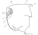
図1は本発明の実施の形態1に係る空気調和機を模式的に示す側面視の中央部における断面図である。図1において、空気調和機100は、筐体10と、筐体10内に設置され、空気を吸引すると共に吸引した空気を吹き出す送風ファン20と、送風ファン20が形成する風路内に配置され、吸引した空気を調和する熱交換器30と、吸引した空気に含まれる塵埃を捕捉するフィルタ40と、フィルタ40を清掃するフィルタ清掃装置50と、を有している。以下、各構成部材について個別に説明する。
[Embodiment 1]
(Air conditioner)
FIG. 1 is a cross-sectional view in a central portion of a side view schematically showing an air conditioner according to
(筐体)
筐体10は、両端面(図示しない)が塞がれた筒状であって、天面(図中、上側)の一部が開口し、該開口部が空気を吸い込む吸込口11を形成し、地面(図中、下側)の一部が開口し、吸込口11から吸い込んだ空気を吹き出す吹出口14を形成している。そして、前面(図中、左側)は開口し、該開口部を開閉する前面扉12が設置されている。なお、後面(図中、右側)は塞がれ、筐体10を壁等に取り付けるための、壁取付部16が形成されている。
そして、筐体10の内部において、後面寄りで天面近くの「位置A」と前面寄りで地面近くの「位置B」とを結ぶ円弧状範囲は、特別の部材が設置されていない空間として用意され、該空間がフィルタ40の移動径路(以下、「円弧状移動径路」と称す)17となっている。
(Casing)
The
In addition, an arcuate range connecting “position A” near the rear surface and near the top surface and “position B” near the front surface and near the ground inside the
(送風ファン)
送風ファン20は、筐体10の側面視で略中央部に配置され、吸込口11から吹出口14に至る風路を形成するものである。送風ファン20と吹出口14との間の吹出側風路は、前面ガイド板13と後面ガイド板15とによって挟まれている。
(Blower fan)
The
(熱交換器)
熱交換器30は、吸込口11と送風ファン20との間に配置され、吸い込まれた空気を調和(冷却、加熱、加湿、除湿等)する。図中、熱交換器30は送風ファン20の天面側および前面側を取り囲むように配置されているが、本発明は該配置形態に限定するものではない。また、熱交換器30は、伝熱管31と、伝熱管31に設置された放熱フィン32とを具備するものを示しているが、本発明はこれに限定するものではない。
(Heat exchanger)
The
(フィルタ)
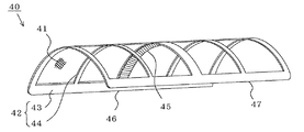
図2は、図1に示すフィルタを模式的に示す斜視図である。図1および図2において、フィルタ40は、フィルタ通気体(網状体)41と、フィルタ通気体が設置されたフィルタ枠体42とから形成されている。フィルタ枠体42は円筒の一部を形成し(断面円弧状であって、いわゆる「八つ橋状」)、矩形状の外枠43と、外枠43の対向する辺を連結する補強桟44とから形成され、補強桟44の内面に内歯車からなるフィルタ従動歯車45が形成されている。
なお、フィルタ40は、円弧状移動径路17に沿って、その上縁46が位置Aに到達し、その下縁47が位置Bに到達する範囲を往復移動するものであって、フィルタ枠体42(フィルタ40に同じ)の断面円弧の曲率半径は、円弧状移動径路17の曲率半径に同じである。すなわち、フィルタ40は曲率半径が変わることなく往復移動するから、フィルタ40を簡素な手段によって移動させることができるだけでなく、フィルタ40自体の劣化が防止されて寿命延長が図られる。
(filter)
FIG. 2 is a perspective view schematically showing the filter shown in FIG. In FIG. 1 and FIG. 2, the
The
(フィルタ清掃装置)
図1において、フィルタ清掃装置50は、フィルタ40を移動させるフィルタ移動部60と、フィルタ40のフィルタ通気体41に当接し、これに捕捉された塵埃を除去する塵埃除去部70と、塵埃除去部70によって除去された塵埃を回収する塵埃回収部80と、を有している。
(Filter cleaning device)
In FIG. 1, a
(フィルタ移動部)
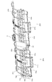
図3は、図1に示すフィルタ清掃装置を模式的に示す斜視図である。図1および図3において、フィルタ移動部60は、フィルタ従動歯車45に噛み合うフィルタ駆動歯車61と、フィルタ駆動歯車61が略中央に固定されたフィルタ駆動軸62と、フィルタ駆動軸62の一方の端部に固定されたフィルタ回転入力歯車63と、フィルタ駆動軸62を回転自在に支持するフィルタ移動部本体64を具備している。
また、フィルタ移動部本体64には、フィルタ駆動軸62と平行にフィルタ押さえ軸65が設置され、フィルタ押さえ軸65は、フィルタ従動歯車45にフィルタ駆動歯車61が噛み合ってフィルタ40が移動される際、該噛み合いが外れないようにしている。なお、フィルタ押さえ軸65は回転自在な断面円形でも、固定された断面矩形でもよい。
さらに、フィルタ移動部本体64には、塵埃回収部80を着脱自在に取り付けるためのフィルタ移動部係止突起66と、筐体10に取り付けおよび筐体10から取り外す際、フィルタ移動部60のハンドリングを容易にするフィルタ移動部ハンドル67が形成されている。
(Filter moving part)
FIG. 3 is a perspective view schematically showing the filter cleaning device shown in FIG. 1. 1 and 3, the
Further, the filter moving part
Further, the filter moving part
(塵埃除去部)
図4は、図1に示す塵埃除去部を模式的に示す斜視図である。図1および図4において、塵埃除去部70は、フィルタ40のフィルタ通気体41の外面に当接して回転するロール状ブラシ71と、ロール状ブラシ71が固定されたロール状ブラシ駆動軸72と、ロール状ブラシ駆動軸72の一方の端部に固定されたロール状ブラシ回転入力歯車73と、ロール状ブラシ駆動軸72を回転自在に支持する塵埃除去部本体74を具備している。
なお、塵埃除去部本体74の一方の端面には円筒状の突起(図示しない、以下、「軸貫通突起」と称す)が形成され、該突起をロール状ブラシ駆動軸72が貫通し、他方の端面には円筒状(端部が閉塞されたコップ状を呈している)の突起(以下、「軸支持突起」と称す)75が形成され、軸支持突起75の内部においてロール状ブラシ駆動軸72の端部が支持されている。
(Dust removal part)
FIG. 4 is a perspective view schematically showing the dust removing unit shown in FIG. 1 and 4, the
A cylindrical protrusion (not shown, hereinafter referred to as “shaft penetrating protrusion”) is formed on one end face of the dust removing portion
そして、ロール状ブラシ71は後記要領で、回転または停止される。
なお、以上は、塵埃除去部70として回転駆動されるロール状ブラシ71を示しているが、本発明はこれに限定するものはなく、ロール状ブラシ71に替えて逆ハ字状に配置された一対の面状ブラシを設置してもよい。すなわち、地面寄りに略水平で後面向きの面状ブラシと天面寄りに略鉛直で地面向きの面状ブラシとを設置し、前者がフィルタ40が下方に移動する際、後者がフィルタ40が上方に移動する際、主に除塵するようにする。
Then, the
Although the above description shows the roll-shaped
(塵埃回収部)
図5は、図1に示す塵埃回収部を模式的に示す斜視図である。図1および図5において、塵埃回収部80は、ロール状ブラシ71に当接して捕捉された塵埃を掻き落とす掻き落し板81と、掻き落し板81をロール状ブラシ71の押し当てるための掻き落し付勢手段82と、掻き落し板81によって掻き落とされた塵埃を溜める集塵箱83と、を具備している。
そして、集塵箱83の一方の端面には奥が僅かに広くなった略Ω字状の切欠部84が形成され、切欠部84に塵埃除去部70の前記軸貫通突起(ロール状ブラシ駆動軸72が貫通している)が係止自在になっている。また、集塵箱83の他方の端面には貫通孔85が形成され、貫通孔85に、塵埃除去部70の軸支持突起75(ロール状ブラシ駆動軸72の端部を支持している)が回転自在に侵入自在になっている。
また、集塵箱83の外面には、フィルタ移動部60のフィルタ移動部係止突起66が係止する塵埃回収部係止突起86と、ハンドリングを容易にする凹部からなる把手部87が形成されている。
(Dust collection part)
FIG. 5 is a perspective view schematically showing the dust collecting section shown in FIG. In FIGS. 1 and 5, the
A substantially Ω-shaped
Further, on the outer surface of the
(フィルタ清掃装置の組み立て)
図6は、図1に示すフィルタ清掃装置を組み立てた様子を示す斜視図である。図6において、塵埃回収部80の貫通孔85に塵埃除去部70の軸支持突起75を侵入し、塵埃回収部80の切欠部84に塵埃除去部70のロール状ブラシ駆動軸72を係止することにより、フィルタ清掃装置50が組み立てられている。このとき、塵埃回収部80と塵埃除去部70とは、前記侵入部および前記係止部を回転中心にして、回転自在に接合されている。
すなわち、塵埃除去部70の塵埃除去部本体74が、塵埃回収部80の集塵箱83の「開閉蓋」として機能するから、塵埃除去部本体74を集塵箱83に合わせると、塵埃除去部本体74、集塵箱83およびロール状ブラシ71の三者によって、略密閉されたダストボックスが形成される。
(Assembly of filter cleaning device)
FIG. 6 is a perspective view showing a state where the filter cleaning device shown in FIG. 1 is assembled. In FIG. 6, the
That is, since the dust removing unit
さらに、塵埃除去部本体74の端面が集塵箱83の内部に侵入しているから、塵埃除去部本体74の端面の外側に小突起または小凹部を形成し、集塵箱83の端面の内側に前記小突起または小凹部に係止自在な小凹部または小突起を形成しておけば、これらが係止することによって塵埃除去部本体74と集塵箱83とが容易に離れなくなるから、前記ダストボックスから塵埃が不用意に散逸することがない。また、該係止は僅かな力でもって分離可能であるから、前記ダストボックスから塵埃を排出する作業が容易になる。
Further, since the end surface of the dust removing unit
(フィルタ清掃装置の取り付け)
図7は、本発明の実施の形態1に係る空気調和機を模式的に示す側面視の端部における断面図である。図7において、空気調和機100の筐体10の端部には、フィルタ清掃装置50を設置するための、清掃装置設置スロープ18が形成されている。したがって、前面扉12を開いて、フィルタ清掃装置50を容易に取り付けまたは取り外すことができる。このとき、フィルタ40を把持しているフィルタ移動部60(図中、右下がりの斜線を付す)と、一体化されている塵埃除去部70と塵埃回収部80と(前記ダストボックスに同じ、図中、左下がりの斜線を付す)を、それぞれ別個に取り付けても、これらを一体的に取り付けてもよい。
なお、以上は、フィルタ移動部60のフィルタ移動部係止突起66と塵埃回収部80の塵埃回収部係止突起86とが、互いに係止するものを例示しているが、本発明はこれに限定するものではない。たとえば、一方の端面に形成した溝部に、他方の端面に形成した突条を係止(または嵌合)してもよいし、筐体10の清掃装置設置スロープ18に、フィルタ移動部60が係止するスロープと、塵埃回収部80が係止するスロープとを、それぞれ形成してもよい。
(Attaching the filter cleaning device)
FIG. 7 is a cross-sectional view at an end portion in a side view schematically showing the air conditioner according to
In the above, the filter moving
(フィルタの移動要領)
図8は、図1に示すフィルタ清掃装置におけるフィルタの移動要領を説明する側面視の断面図である。図8において、フィルタ40は下降限にまで移動されている。すなわち、フィルタ40は円弧状移動径路17にそって、上縁46が位置Aにあった状態(図1参照)から、下縁47が位置Bに到達するまで移動している。
そして、位置Aから位置Bに向かう「往路」において、ロール状ブラシ71は、フィルタ40の移動方向(図中、略下方向)と同一の方向(図中、時計回り)に回転し、フィルタ通気体41に捕捉された塵埃を除去する。特に、ロール状ブラシ71の周速(Vb)がフィルタ40の移動速度(Vf)よりも遅く(Vb<Vf)なっているから、フィルタ通気体41に捕捉された塵埃は、一旦、ロール状ブラシ71の噛み込み側(図中、天面側)に集められた後、ロール状ブラシ71に付着して噛み出し側(図中、地面側)に運ばれることになる。そして、該付着した塵埃は掻き落し板81によって掻き落とされ、集塵箱83内に回収される。
(How to move the filter)
FIG. 8 is a cross-sectional view in side view for explaining a moving procedure of the filter in the filter cleaning device shown in FIG. 1. In FIG. 8, the
In the “outward path” from position A to position B, the
一方、下降限に到達していたフィルタ40は、今度は逆転(図中、時計回り)するフィルタ駆動歯車61によって移動させられ、上昇限にまで戻る(図1参照)。すなわち、上縁46が位置Aに到達する。
そして、位置Bから位置Aに向かう「復路」において、ロール状ブラシ71は回転を停止している。したがって、往路において除去されないまま残っていた塵埃が、復路において除去されたとしても、該塵埃は、回転していないロール状ブラシ71の噛み込み側(図中、地面側)に集まるだけで、噛み出し側(図中、天面側)に運ばれることがない。よって、ロール状ブラシ71から除去された塵埃が集塵箱83の外に散逸することがない。
On the other hand, the
In the “return path” from the position B to the position A, the
[実施の形態2]
(空気調和機)
図9および図10は本発明の実施の形態2に係る空気調和機に設置されるフィルタ清掃装置を模式的に示す斜視図であって、図9は組み立て前、図10は組み立て後である。
図9および図10において、空気調和機200(図示しない)は、筐体10と、筐体10内に設置され、空気を吸引すると共に吸引した空気を吹き出す送風ファン20と、送風ファン20が形成する風路内に配置され、吸引した空気を調和する熱交換器30と、吸引した空気に含まれる塵埃を捕捉する第1フィルタ40aおよび第2フィルタ40bと、第1フィルタ40aおよび第2フィルタ40bをそれぞれ清掃する第1フィルタ清掃装置50aおよび第2フィルタ清掃装置50bと、第1フィルタ清掃装置50aまたは第2フィルタ清掃装置50bに択一的に回転を出力する回転出力装置90と、を有している。
[Embodiment 2]
(Air conditioner)
9 and 10 are perspective views schematically showing a filter cleaning device installed in the air conditioner according to Embodiment 2 of the present invention. FIG. 9 is before assembly, and FIG. 10 is after assembly.
9 and 10, an air conditioner 200 (not shown) is formed by a
第1フィルタ40aおよび第2フィルタ40bは、何れも実施の形態1におけるフィルタ40に同じである。
図中、右側に配置された第1フィルタ清掃装置50aは、実施の形態1におけるフィルタ清掃装置50に同じであって、その左側の端部に第1フィルタ回転入力歯車63aおよび第1ロール状ブラシ回転入力歯車73aが位置している。一方、図中、左側に配置された第2フィルタ清掃装置50bは、その右側の端部に第2フィルタ回転入力歯車63bおよび第2ロール状ブラシ回転入力歯車73bが位置している点において第1フィルタ清掃装置50aと相異するものの、これをのぞく構成は第1フィルタ清掃装置50aに同じ(実施の形態1に示すフィルタ清掃装置50に同じ)である。つまり、かかるフィルタ回転入力歯車63a、73a、63b、73bは、正面視で筐体の中央部に集中している。
The
In the drawing, the first
(回転出力装置)
回転出力装置90は、1台のモータ(図示しない)と、第1フィルタ回転入力歯車63aに噛み合い自在な第1フィルタ回転出力歯車96aと、第1ロール状ブラシ回転入力歯車73aに噛み合い自在な第1ロール状ブラシ回転出力歯車97aと、第2フィルタ回転入力歯車63bに噛み合い自在な第2フィルタ回転出力歯車96bと、第2ロール状ブラシ回転入力歯車73bに噛み合い自在な第2ロール状ブラシ回転出力歯車97b(以下、これらをまとめて「フィルタ回転出力歯車91」と称する場合がある)と、を具備している。すなわち、回転出力装置90は、1台のモータの回転をフィルタ回転出力歯車91のいずれかに択一的に伝える回転分配機構(図示しない)と、フィルタ回転出力歯車91のいずれかの回転を択一的に停止する回転停止機構(図示しない)と、を具備している。
なお、回転出力装置90は筐体10に固定されているから、第1フィルタ清掃装置50aおよび第2フィルタ清掃装置50bが筐体10に取り付けられた状態で、前記それぞれの歯車同士は噛み合うものである。
(Rotation output device)
The
Since the
(フィルタの移動要領)
回転出力装置90は、前記のように、フィルタ回転出力歯車91と、回転分配機構と、回転停止機構とを具備しているから、第1フィルタ40aおよび第2フィルタ40bは、以下の要領で移動する(清掃されるに同じ)。
すなわち、第1フィルタ40aが位置Aから位置Bに向かって移動(往路移動)し、該往路移動が終了した後、第2フィルタ40bが位置Aから位置Bに向かって移動(往路移動)する。そして、両者の往路移動が終了した後、第1フィルタ40aが位置Bから位置Aに向かって移動(復路移動)し、該復路移動が終了した後、第2フィルタ40bが位置Bから位置Aに向かって移動(復路移動)する。
(How to move the filter)
Since the
That is, the
そして、前記往路移動において、第1ロール状ブラシ71aの周速度が第1フィルタ40aの移動速度より小さくなるように、第1ロール状ブラシ回転出力歯車97aと第1フィルタ回転出力歯車96aとは、それぞれ所定の回転数(回転数比に同じ)で反対方向に回転する。同様に、第2ロール状ブラシ71bの周速度が第2フィルタ40bの移動速度より小さくなるように、第2ロール状ブラシ回転出力歯車97bと第2フィルタ回転出力歯車96bとは、それぞれ所定の回転数(回転数比に同じ)で反対方向に回転する。
さらに、前記復路移動において、第1ロール状ブラシ回転出力歯車97aは回転を停止したまま、第1フィルタ回転出力歯車96aが回転し、同様に、第2ロール状ブラシ回転出力歯車97bは回転を停止したまま、第2フィルタ回転出力歯車96bが回転する。
In the forward movement, the first roll-shaped brush rotation output gear 97a and the first filter rotation-output gear 96a are set so that the peripheral speed of the first roll-shaped brush 71a is smaller than the movement speed of the
Further, in the backward movement, the first filter rotation output gear 96a rotates while the first roll brush rotation output gear 97a stops rotating, and similarly, the second roll brush
したがって、実施の形態1と同様に、第1フィルタ40aおよび第2フィルタ40bに捕捉された塵埃は除去されて第1集塵箱83aおよび第2集塵箱83b内に回収される。このとき、第1フィルタ40aおよび第2フィルタ40bは、それぞれ1台のモータによって移動されるものであって、しかも、択一的に時間をズラせているから、該モータの容量を小さくすることができる。よって、空気調和機200の製造コストの上昇が抑えられる。
なお、以上は、第1フィルタ40aおよび第2フィルタ40bの両方の往路移動が終了した後に復路移動を開始しているが、本発明はこれに限定するものではなく、第1フィルタ40aの往路移動および復路移動が終了した後に、第2フィルタ40bの往路移動を開始してもよい。
Therefore, as in the first embodiment, the dust trapped by the
In the above, the backward movement is started after the forward movement of both the
(フィルタ確認スイッチ)
図11は、本発明の実施の形態2に係る空気調和機に設置されるフィルタ確認スイッチを模式的に示す斜視図である。フィルタ確認スイッチ(以下、「スイッチ」と称す)9は、筐体10の位置Aに設置されるものであって、筐体10側に固定されたスイッチベース1と、スイッチベース1に固定されたスイッチボックス2と、スイッチボックス2内に固定された固定接点(図示しない)と、スイッチボックス2内に移動自在に配置され前記固定接点に短絡および絶縁自在な移動接点(図示しない)と、該移動接点を具備しスイッチボックス2から突出して進退する進退部3と、進退部3に当接自在でこれを後退可能なレバー4とを有している。
(Filter confirmation switch)
FIG. 11 is a perspective view schematically showing a filter confirmation switch installed in the air conditioner according to Embodiment 2 of the present invention. A filter confirmation switch (hereinafter referred to as “switch”) 9 is installed at a position A of the
レバー4は中央に支持突起(図示しない)が設置され、該支持突起はスイッチベース1に形成された案内溝6に案内されて並進自在および回転自在であって、進退部3から離れる方向に付勢手段(図示しない)または重力によって付勢されている。すなわち、レバー4は進退すると共に傾動する(シーソー状に動く)。
よって、第1フィルタ40aの上縁46aがレバー4の一方の端部に形成された第1当接部5aに当接したとき、レバー4は傾動して、第1当接部5aは上昇し、レバー4の他方の端部に形成された第2当接部5bは下降する。同様に、第2フィルタ40bの上縁46bがレバー4の第2当接部5bに当接したとき、レバー4は傾動して、第2当接部5bは上昇し、第1当接部5aは下降する。
一方、第1フィルタ40aの上縁46aおよび第2フィルタ40bの上縁46bの両方が、それぞれレバー4の第1当接部5aおよび第2当接部5bに当接したとき、レバー4は傾動することなく押し上げられるから、レバー4は進退部3に当接して進退部3を後退させる。よって、進退部3の該後退によって固定側接点と移動側接点とは短絡する。
The lever 4 is provided with a support protrusion (not shown) in the center, and the support protrusion is guided by a guide groove 6 formed in the
Therefore, when the upper edge 46a of the
On the other hand, when both the upper edge 46a of the
すなわち、空気調和機200には、スイッチ9が設置されているから、第1フィルタ.清掃装置50aおよび第2フィルタ清掃装置50bを取り付けた際、これらが正規の位置に設置されていることが容易に確認される。また、第1フィルタ40aまたは第2フィルタ40bの一方または両方の移動を開始する際、あるいは該移動を終了した際、第1フィルタ40aおよび第2フィルタ40bがいずれも上昇限(位置A)にあることが容易に確認される。このとき、スイッチ9は1台であって、構造が簡素かつ小型であるから、筐体10への設置が容易であると共に、空気調和機200の製造コストの上昇が抑えられる。
That is, since the
本発明は以上の構成であるから、フィルタを機内に隠した状態のまま清掃することができると共に、1台のモータでもって複数のフィルタを清掃することができるから、各種装置に設置されるフィルタ清掃装置として、および各種空気調和機として広く利用することができる。 Since the present invention has the above configuration, the filter can be cleaned while being hidden in the machine, and a plurality of filters can be cleaned with a single motor. It can be widely used as a cleaning device and as various air conditioners.
1:スイッチベース、2:スイッチボックス、3:進退部、4:レバー、5a:第1当接部、5b:第2当接部、6:案内溝、9:スイッチ、10:筐体、11:吸込口、12:前面扉、13:前面ガイド板、14:吹出口、15:後面ガイド板、16:壁取付部、17:円弧状移動径路、18:清掃装置設置スロープ、20:送風ファン、30:熱交換器、31:伝熱管、32:放熱フィン、40:フィルタ、41:フィルタ通気体、42:フィルタ枠体、43:外枠、44:補強桟、45:フィルタ従動歯車、46:上縁、47:下縁、50:フィルタ清掃装置、60:フィルタ移動部、61:フィルタ駆動歯車、62:フィルタ駆動軸、63:フィルタ回転入力歯車、64:フィルタ移動部本体、66:フィルタ移動部係止突起、67:フィルタ移動部ハンドル、70:塵埃除去部、71:ロール状ブラシ、72:ロール状ブラシ駆動軸、73:ロール状ブラシ回転入力歯車、74:塵埃除去部本体、75:軸支持突起、80:塵埃回収部、81:掻き落し板、82:付勢手段、84:切欠部、85:貫通孔、86:塵埃回収部係止突起、87:把手部、90:回転出力装置、91:フィルタ回転出力歯車、96a:第1フィルタ回転出力歯車、96b:第2フィルタ回転出力歯車、97a:第1ロール状ブラシ回転出力歯車、97b:第2ロール状ブラシ回転出力歯車、100:空気調和機、200:空気調和機。 1: switch base, 2: switch box, 3: forward / backward part, 4: lever, 5a: first contact part, 5b: second contact part, 6: guide groove, 9: switch, 10: housing, 11 : Suction port, 12: Front door, 13: Front guide plate , 14: Air outlet, 15: Rear guide plate, 16: Wall mounting part, 17: Circular moving path, 18: Cleaning device installation slope, 20: Blower fan , 30: heat exchanger, 31: heat transfer tube, 32: radiating fin, 40: filter, 41: filter vent, 42: filter frame, 43: outer frame, 44: reinforcing bar, 45: filter driven gear, 46 : Upper edge, 47: Lower edge, 50: Filter cleaning device, 60: Filter moving part, 61: Filter driving gear, 62: Filter driving shaft, 63: Filter rotation input gear, 64: Filter moving part main body, 66: Filter Moving part locking projection, 67 Filter moving part handle, 70: Dust removing part, 71: Roll brush, 72: Roll brush driving shaft, 73: Roll brush input gear, 74: Dust removing body, 75: Shaft support protrusion, 80: Dust Collection part, 81: scraping plate, 82: biasing means, 84: notch, 85: through hole, 86: dust collection part locking projection, 87: handle part, 90: rotation output device, 91: filter rotation output 96a: first filter rotation output gear, 96b: second filter rotation output gear, 97a: first roll brush rotation output gear, 97b: second roll brush rotation output gear, 100: air conditioner, 200: Air conditioner.
Claims (10)
該筐体内に設置され、前記吸込口から吸い込んだ空気を前記吹出口から吹き出す送風ファンと、
前記送風ファンと前記吹出口との間の吹出側風路を形成する前面ガイド板および後面ガイド板と、
前記送風ファンが形成する空気の流れの中に設置された熱交換器と、
前記吸込口と前記熱交換器との間に配置され、前記吸込口から吸い込んだ空気中の塵埃を捕捉するフィルタと、
前記筐体に設置され、前記フィルタを清掃するフィルタ清掃装置と、を有し、
前記フィルタ清掃装置が、前記フィルタを移動させるフィルタ移動部と、前記フィルタに当接して前記フィルタに捕捉された塵埃を除去する塵埃除去部と、該塵埃除去部によって除去された塵埃を回収する塵埃回収部と、を有し、
前記フィルタ移動部が、前記フィルタを、前記筐体内の円弧状移動径路に沿って、その上縁が前記筐体内の後面寄りで天面側の位置に到達し、その下縁が前記筐体内の前面寄りで前記前面ガイド板の位置に到達する範囲を、往復移動させることを特徴とする空気調和機。 A housing having a suction port that opens to the top surface side and sucks air; and a blower port that opens to the ground side and blows out the sucked air;
A blower fan that is installed in the housing and blows out the air sucked from the suction port from the air outlet;
A front guide plate and a rear guide plate that form a blow-out side air passage between the blower fan and the outlet;
A heat exchanger installed in the flow of air formed by the blower fan;
A filter that is disposed between the suction port and the heat exchanger and captures dust in the air sucked from the suction port;
A filter cleaning device installed in the housing and cleaning the filter;
The filter cleaning device moves the filter, a filter moving unit, a dust removing unit that contacts the filter and removes dust captured by the filter, and dust that collects the dust removed by the dust removing unit A recovery unit,
The filter moving section, the filter, along the arcuate movement path in the housing, the upper edge of the filter reaches a position on the top surface side near the rear surface in the housing, and the lower edge of the filter moves in the housing. An air conditioner that reciprocates a range that reaches the position of the front guide plate near the front .
該筐体内に設置され、前記吸込口から吸い込んだ空気を前記吹出口から吹き出す送風ファンと、
前記送風ファンと前記吹出口との間の吹出側風路を形成する前面ガイド板および後面ガイド板と、
前記送風ファンが形成する空気の流れの中に設置された熱交換器と、
前記吸込口と前記熱交換器との間に配置され、前記吸込口から吸い込んだ空気中の塵埃を捕捉する第1フィルタおよび第2フィルタと、
前記筐体に設置され、前記第1フィルタおよび第2フィルタをそれぞれ清掃する第1フィルタ清掃装置および第2フィルタ清掃装置と、を有する空気調和機であって、
前記第1フィルタ清掃装置および第2フィルタ清掃装置がそれぞれ、前記第1フィルタおよび第2フィルタを移動させる第1フィルタ移動部および第2フィルタ移動部と、前記第1フィルタおよび第2フィルタに当接して前記第1フィルタおよび第2フィルタに捕捉された塵埃を除去する第1塵埃除去部および第2塵埃除去部と、該第1塵埃除去部および第2塵埃除去部によって除去された塵埃を回収する第1塵埃回収部および第2塵埃回収部と、を有し、
前記第1フィルタ移動部および第2フィルタ移動部が、前記第1フィルタおよび第2フィルタを、前記筐体内の円弧状移動径路に沿って、その上縁が前記筐体内の後面寄りで天面側の位置に到達し、その下縁が前記筐体内の前面寄りで前記前面ガイド板の位置に到達する範囲を、往復移動させ、
前記第1フィルタが移動している間、前記第2フィルタは停止し、一方、前記第2フィルタが移動している間、前記第1フィルタは停止することを特徴とする空気調和機。 A housing having a suction port that opens to the top surface side and sucks air; and a blower port that opens to the ground side and blows out the sucked air;
A blower fan that is installed in the housing and blows out the air sucked from the suction port from the air outlet;
A front guide plate and a rear guide plate that form a blow-out side air passage between the blower fan and the outlet;
A heat exchanger installed in the flow of air formed by the blower fan;
A first filter and a second filter which are disposed between the suction port and the heat exchanger and capture dust in the air sucked from the suction port;
An air conditioner having a first filter cleaning device and a second filter cleaning device installed in the housing and cleaning the first filter and the second filter, respectively.
The first filter cleaning device and the second filter cleaning device are in contact with a first filter moving portion and a second filter moving portion that move the first filter and the second filter, respectively, and the first filter and the second filter. A first dust removing section and a second dust removing section for removing dust trapped by the first filter and the second filter, and collecting the dust removed by the first dust removing section and the second dust removing section. A first dust collecting part and a second dust collecting part;
The first filter moving unit and the second filter moving unit move the first filter and the second filter along the arcuate moving path in the casing, and the upper edge is close to the rear surface in the casing and is on the top surface side. The range where the lower edge reaches the position of the front guide plate near the front surface in the housing is reciprocated,
The air conditioner is characterized in that the second filter is stopped while the first filter is moving, and the first filter is stopped while the second filter is moving.
前記第2フィルタが前記筐体内の後面寄りで天面側の位置から前面寄りで地面側の位置に向けて後面寄りで天面側の位置に向けて移動する際、前記第2フィルタ清掃装置の前記ロール状ブラシ回転機構が、前記ロール状ブラシを前記第2フィルタの移動速度よりも小さな周速で前記移動方向に向けて回転し、
前記第1フィルタが前記筐体内の前面寄りで地面側の位置から後面寄りで天面側の位置に向けて移動する際、前記第1フィルタ清掃装置を構成する前記ロール状ブラシが停止し、
前記第2フィルタが前記筐体内の前面寄りで地面側の位置から後面寄りで天面側の位置に向けて移動する際、前記第2フィルタ清掃装置を構成する前記ロール状ブラシが停止する、
ことを特徴とする請求項2記載の空気調和機。 When the first filter moves from the position on the top surface side near the rear surface in the housing toward the position on the ground side near the front surface, the roll brush constituting the first filter cleaning device is the first filter. Rotate in the direction of movement at a peripheral speed smaller than the moving speed of
When the second filter moves from the position on the top surface side near the rear surface in the housing to the position on the ground side near the front surface and toward the position on the top surface side near the rear surface, the second filter cleaning device The roll brush rotating mechanism rotates the roll brush toward the moving direction at a peripheral speed smaller than the moving speed of the second filter,
When the first filter moves from the position on the ground side near the front surface in the housing toward the position on the top surface side near the rear surface, the roll brush constituting the first filter cleaning device stops,
When the second filter moves from the position on the ground side near the front surface in the housing toward the position on the top surface side near the rear surface, the roll brush constituting the second filter cleaning device stops,
The air conditioner according to claim 2.
前記第2フィルタ清掃装置を構成するフィルタ駆動歯車回転機構が、前記第2フィルタに形成された第2フィルタ従動歯車に噛み合う第2フィルタ駆動歯車と、該第2フィルタ駆動歯車が固定された第2フィルタ駆動軸と、該第2フィルタ駆動軸に固定された第2フィルタ回転入力歯車と、を具備し、
前記第1フィルタ清掃装置を構成するロール状ブラシ回転機構が、第1ロール状ブラシと、該第1ロール状ブラシが固定された第1ロール状ブラシ駆動軸と、該第1ロール状ブラシ駆動軸に固定された第1ロール状ブラシ回転入力歯車と、を具備し、
前記第2フィルタ清掃装置を構成するロール状ブラシ回転機構が、第2ロール状ブラシと、該第2ロール状ブラシが固定された第2ロール状ブラシ駆動軸と、該第2ロール状ブラシ駆動軸に固定された第2ロール状ブラシ回転入力歯車と、を具備し、
前記筐体に、1台のモータを具備する回転出力装置が設置され、
該回転出力装置が、前記第1フィルタ回転入力歯車に噛み合う第1フィルタ回転出力歯車と、前記第2フィルタ回転入力歯車に噛み合う第2フィルタ回転出力歯車と、前記第1ロール状ブラシ回転入力歯車に噛み合う第1ロール状ブラシ回転出力歯車と、前記第2ロール状ブラシ回転入力歯車に噛み合う第2ロール状ブラシ回転出力歯車と、を具備するとともに、
前記第1フィルタ回転出力歯車または前記第2フィルタ回転出力歯車の一方を択一的に回転させることを特徴とする請求項2または3記載の空気調和機。 The filter drive gear rotation mechanism constituting the first filter cleaning device includes a first filter drive gear meshing with a first filter driven gear formed in the first filter, and a first filter drive gear fixed to the first filter drive gear. A filter drive shaft, and a first filter rotation input gear fixed to the first filter drive shaft,
The filter drive gear rotation mechanism constituting the second filter cleaning device includes a second filter drive gear meshing with a second filter driven gear formed on the second filter, and a second filter drive gear fixed to the second filter drive gear. A filter drive shaft, and a second filter rotation input gear fixed to the second filter drive shaft,
The roll brush rotating mechanism constituting the first filter cleaning device includes a first roll brush, a first roll brush drive shaft to which the first roll brush is fixed, and the first roll brush drive shaft. A first roll-shaped brush rotation input gear fixed to
The roll brush rotating mechanism constituting the second filter cleaning device includes a second roll brush, a second roll brush drive shaft to which the second roll brush is fixed, and the second roll brush drive shaft. A second roll-shaped brush rotation input gear fixed to
A rotation output device having one motor is installed in the housing,
The rotation output device includes a first filter rotation output gear meshing with the first filter rotation input gear, a second filter rotation output gear meshing with the second filter rotation input gear, and the first roll-shaped brush rotation input gear. A first roll brush rotation output gear meshing with the second roll brush rotation output gear meshing with the second roll brush rotation input gear;
The air conditioner according to claim 2 or 3, wherein one of the first filter rotation output gear and the second filter rotation output gear is selectively rotated.
該固定接点に短絡および絶縁自在な移動接点と、
該移動接点を備え、前記固定接点に対して進退自在な進退部と、
該進退部に当接自在で前記進退部を後退可能な傾動レバーと、
該傾動レバーの中央部を傾動自在かつ進退自在に支持するレバー支持手段と、
前記傾動レバーを前記進退部から遠ざける方向に付勢する付勢手段と、
を具備し、
前記第1フィルタまたは前記第2フィルタの一方の上縁が、前記筐体の後面寄りで天面側に到達した際、前記固定側接点と前記移動側接点とは絶縁のまま、前記傾動レバーが傾動し、
前記第1フィルタおよび前記第2フィルタの両方の上縁が、前記筐体の後面寄りで天面側に到達した際、前記傾動レバーは後退して前記進退部に当接し、この傾動レバーの進退部への当接によって前記進退部が後退し、前記固定側接点と前記移動側接点とが短絡する、
ことを特徴とする請求項2乃至4の何れかに記載の空気調和機。 A fixed contact installed near the top surface near the rear surface of the housing;
A movable contact that can be short-circuited and insulated to the fixed contact;
An advancing / retreating portion that includes the moving contact and is movable relative to the fixed contact;
A tilting lever capable of abutting on the advancing / retreating part and retracting the advancing / retreating part;
Lever support means for supporting the central portion of the tilt lever so as to be tiltable and advanceable and retractable;
Urging means for urging the tilting lever in a direction away from the advancing / retreating portion;
Comprising
When the upper edge of one of the first filter or the second filter reaches the top surface near the rear surface of the housing, the fixed lever and the moving contact remain insulated, and the tilt lever Tilt and
When the upper edges of both the first filter and the second filter reach the top surface near the rear surface of the housing, the tilting lever moves backward and comes into contact with the forward / backward moving portion. The advancing / retreating part is retracted by contact with the part, and the fixed contact and the moving contact are short-circuited,
The air conditioner according to any one of claims 2 to 4, wherein the air conditioner is provided.
前記フィルタ移動部が、前記フィルタ従動歯車に噛み合うフィルタ駆動歯車と、該フィルタ駆動歯車を回転するフィルタ駆動歯車回転機構と、前記フィルタ従動歯車に前記フィルタ駆動歯車が噛み合っている状態で、前記フィルタの外面に当接するフィルタ押さえ機構と、
を有することを特徴とする請求項1または2記載の空気調和機。 The filter is a cross-sectional arc having a curvature radius substantially the same as the curvature radius of the arcuate moving path, and has a filter driven gear made of an internal gear on its inner surface,
The filter moving portion is engaged with the filter driven gear, the filter driving gear rotating mechanism for rotating the filter driving gear, and the filter driving gear in mesh with the filter driven gear. A filter holding mechanism that contacts the outer surface;
The air conditioner according to claim 1 or 2, characterized by comprising:
前記フィルタ駆動歯車回転機構が、前記フィルタを前記筐体内の後面寄りで天面側の位置から前面寄りで地面側の位置に向けて移動させる際、前記ロール状ブラシ回転機構が、前記ロール状ブラシを前記フィルタの移動速度よりも小さな周速で前記移動方向に向けて回転させ、
前記フィルタ駆動歯車回転機構が、前記フィルタを前記筐体内の前面寄りで地面側の位置から後面寄りで天面側の位置に向けて移動させる際、前記ロール状ブラシ回転機構が前記ロール状ブラシを停止させる、
ことを特徴とする請求項1または2記載の空気調和機。 The dust removing unit has a roll-shaped brush that can freely come into contact with the outer surface of the filter, and a roll-shaped brush rotation mechanism that rotates the roll-shaped brush,
When the filter driving gear rotation mechanism moves the filter from the position on the top surface side near the rear surface in the housing toward the position on the ground side near the front surface, the roll brush rotation mechanism is configured to move the roll brush. Is rotated in the moving direction at a peripheral speed smaller than the moving speed of the filter,
When the filter drive gear rotation mechanism moves the filter from the position on the ground side near the front surface in the housing toward the position on the top surface side near the rear surface, the roll-shaped brush rotation mechanism moves the roll-shaped brush. To stop,
The air conditioner according to claim 1 or 2, wherein
を具備することを特徴とする請求項1または2記載の空気調和機。 The dust collecting part is scraped off by the dust scraping plate that abuts against the roll brush and scrapes the dust, urging means that presses the dust scraping plate against the roll brush, and the dust scraping plate. A dust collection box that collects dust,
The air conditioner according to claim 1 or 2, further comprising:
前記蓋体に前記塵埃除去部のロール状ブラシが設置され、
前記蓋体が前記集塵箱の開口部を閉じた際、前記塵埃掻き落とし板が前記付勢手段によって前記ロール状ブラシに押し付けられることを特徴とする請求項1または2記載の空気調和機。 A lid that opens and closes the opening of the dust collection box of the dust collecting unit is detachably and rotatably installed in the opening.
A roll brush of the dust removing unit is installed on the lid,
The air conditioner according to claim 1 or 2, wherein when the lid closes the opening of the dust collection box, the dust scraping plate is pressed against the roll brush by the urging means.
Priority Applications (1)
| Application Number | Priority Date | Filing Date | Title |
|---|---|---|---|
| JP2006121519A JP4532432B2 (en) | 2006-04-26 | 2006-04-26 | Air conditioner |
Applications Claiming Priority (1)
| Application Number | Priority Date | Filing Date | Title |
|---|---|---|---|
| JP2006121519A JP4532432B2 (en) | 2006-04-26 | 2006-04-26 | Air conditioner |
Publications (3)
| Publication Number | Publication Date |
|---|---|
| JP2007292399A JP2007292399A (en) | 2007-11-08 |
| JP2007292399A5 JP2007292399A5 (en) | 2008-08-21 |
| JP4532432B2 true JP4532432B2 (en) | 2010-08-25 |
Family
ID=38763173
Family Applications (1)
| Application Number | Title | Priority Date | Filing Date |
|---|---|---|---|
| JP2006121519A Active JP4532432B2 (en) | 2006-04-26 | 2006-04-26 | Air conditioner |
Country Status (1)
| Country | Link |
|---|---|
| JP (1) | JP4532432B2 (en) |
Cited By (1)
| Publication number | Priority date | Publication date | Assignee | Title |
|---|---|---|---|---|
| CN109654599A (en) * | 2018-10-26 | 2019-04-19 | 青岛海尔空调器有限总公司 | A kind of wall-hanging air conditioner indoor unit and control method |
Families Citing this family (14)
| Publication number | Priority date | Publication date | Assignee | Title |
|---|---|---|---|---|
| EP2233853A4 (en) * | 2007-12-11 | 2017-01-25 | Daikin Industries, Ltd. | Indoor unit for air conditioner |
| JP4433053B2 (en) * | 2008-01-16 | 2010-03-17 | ダイキン工業株式会社 | Indoor unit of air conditioner |
| JP4618449B2 (en) * | 2008-01-18 | 2011-01-26 | 株式会社富士通ゼネラル | Air conditioner |
| JP4849079B2 (en) * | 2008-02-05 | 2011-12-28 | ダイキン工業株式会社 | Air conditioning indoor unit |
| JP2009186079A (en) * | 2008-02-05 | 2009-08-20 | Daikin Ind Ltd | Air-conditioning indoor unit |
| KR101460715B1 (en) * | 2008-03-14 | 2014-11-12 | 엘지전자 주식회사 | Air conditioner |
| JP5062113B2 (en) * | 2008-09-09 | 2012-10-31 | ダイキン工業株式会社 | Air conditioner indoor unit |
| JP5099030B2 (en) * | 2009-01-30 | 2012-12-12 | 株式会社富士通ゼネラル | Air conditioner |
| JP5591020B2 (en) * | 2010-08-11 | 2014-09-17 | 三菱重工業株式会社 | Air conditioner |
| JP5175943B2 (en) * | 2011-01-11 | 2013-04-03 | シャープ株式会社 | Filter cleaning device, dust box and air conditioner |
| JP6262095B2 (en) * | 2014-08-07 | 2018-01-17 | 三菱電機株式会社 | Filter cleaning device for air conditioner and air conditioner |
| CN105910178A (en) * | 2016-05-06 | 2016-08-31 | 广东美的制冷设备有限公司 | Air conditioner and cleaning control method thereof |
| CN113203145B (en) * | 2021-04-26 | 2022-07-19 | 惠瑞净化科技(江苏)有限公司 | Lithium cell toilet uses safe exhaust system |
| CN115540173A (en) * | 2022-08-09 | 2022-12-30 | 青岛海尔空调器有限总公司 | Air conditioner control method and system and related equipment |
Citations (6)
| Publication number | Priority date | Publication date | Assignee | Title |
|---|---|---|---|---|
| JPS62145019U (en) * | 1986-03-07 | 1987-09-12 | ||
| JPH06229577A (en) * | 1993-02-02 | 1994-08-16 | Toshiba Corp | Indoor unit for air-conditioning device |
| JP2004028487A (en) * | 2002-06-27 | 2004-01-29 | Fujitsu General Ltd | Air conditioner |
| JP2004044933A (en) * | 2002-07-12 | 2004-02-12 | Fujitsu General Ltd | Air conditioner |
| JP2004301363A (en) * | 2003-03-28 | 2004-10-28 | Fujitsu General Ltd | Air conditioner |
| JP2005024134A (en) * | 2003-06-30 | 2005-01-27 | Fujitsu General Ltd | Air conditioner |
Family Cites Families (1)
| Publication number | Priority date | Publication date | Assignee | Title |
|---|---|---|---|---|
| EP1826501B1 (en) * | 2004-10-27 | 2017-12-27 | Panasonic Intellectual Property Management Co., Ltd. | Air conditioning apparatus provided with indoor unit having air filter automatic cleaning function |
-
2006
- 2006-04-26 JP JP2006121519A patent/JP4532432B2/en active Active
Patent Citations (6)
| Publication number | Priority date | Publication date | Assignee | Title |
|---|---|---|---|---|
| JPS62145019U (en) * | 1986-03-07 | 1987-09-12 | ||
| JPH06229577A (en) * | 1993-02-02 | 1994-08-16 | Toshiba Corp | Indoor unit for air-conditioning device |
| JP2004028487A (en) * | 2002-06-27 | 2004-01-29 | Fujitsu General Ltd | Air conditioner |
| JP2004044933A (en) * | 2002-07-12 | 2004-02-12 | Fujitsu General Ltd | Air conditioner |
| JP2004301363A (en) * | 2003-03-28 | 2004-10-28 | Fujitsu General Ltd | Air conditioner |
| JP2005024134A (en) * | 2003-06-30 | 2005-01-27 | Fujitsu General Ltd | Air conditioner |
Cited By (2)
| Publication number | Priority date | Publication date | Assignee | Title |
|---|---|---|---|---|
| CN109654599A (en) * | 2018-10-26 | 2019-04-19 | 青岛海尔空调器有限总公司 | A kind of wall-hanging air conditioner indoor unit and control method |
| CN109654599B (en) * | 2018-10-26 | 2021-03-16 | 青岛海尔空调器有限总公司 | Wall-mounted air conditioner indoor unit and control method |
Also Published As
| Publication number | Publication date |
|---|---|
| JP2007292399A (en) | 2007-11-08 |
Similar Documents
| Publication | Publication Date | Title |
|---|---|---|
| JP4532432B2 (en) | Air conditioner | |
| JP4779771B2 (en) | Recessed ceiling air conditioner | |
| JP5276166B2 (en) | Air conditioner | |
| CN1289872C (en) | Air conditioner | |
| JP4410251B2 (en) | Air conditioner with indoor unit with automatic air filter cleaning function | |
| JP4485509B2 (en) | Filter cleaning device and air conditioner | |
| JP4384115B2 (en) | Air conditioner with indoor unit with automatic air filter cleaning function | |
| JP2007292399A5 (en) | ||
| JP2006145208A (en) | Air conditioner | |
| JP4533366B2 (en) | Filter, filter cleaning device, and air conditioner | |
| JP7134739B2 (en) | Filter cleaning unit and air conditioner | |
| JP5503953B2 (en) | Air conditioner indoor unit | |
| WO2008038570A1 (en) | Air conditioner | |
| JP5007112B2 (en) | Air conditioner indoor unit | |
| WO2018047365A1 (en) | Filter cleaning device | |
| JP5284762B2 (en) | Filter cleaning device and air conditioning device | |
| JP4755065B2 (en) | Air conditioner | |
| JP2006183997A (en) | Air conditioner | |
| JP2012107816A (en) | Air conditioner | |
| JP4763574B2 (en) | Air conditioner | |
| JP5547616B2 (en) | Air conditioner | |
| JP5538176B2 (en) | Air conditioner indoor unit | |
| JP5118452B2 (en) | Air conditioner | |
| JP2008116089A (en) | Filter cleaning device and air conditioner | |
| CN215181512U (en) | Control device for online image detection equipment |
Legal Events
| Date | Code | Title | Description |
|---|---|---|---|
| A521 | Request for written amendment filed |
Free format text: JAPANESE INTERMEDIATE CODE: A523 Effective date: 20080708 |
|
| A621 | Written request for application examination |
Free format text: JAPANESE INTERMEDIATE CODE: A621 Effective date: 20080708 |
|
| A977 | Report on retrieval |
Free format text: JAPANESE INTERMEDIATE CODE: A971007 Effective date: 20091008 |
|
| A131 | Notification of reasons for refusal |
Free format text: JAPANESE INTERMEDIATE CODE: A131 Effective date: 20091013 |
|
| A521 | Request for written amendment filed |
Free format text: JAPANESE INTERMEDIATE CODE: A523 Effective date: 20091112 |
|
| A131 | Notification of reasons for refusal |
Free format text: JAPANESE INTERMEDIATE CODE: A131 Effective date: 20100309 |
|
| A521 | Request for written amendment filed |
Free format text: JAPANESE INTERMEDIATE CODE: A523 Effective date: 20100420 |
|
| TRDD | Decision of grant or rejection written | ||
| A01 | Written decision to grant a patent or to grant a registration (utility model) |
Free format text: JAPANESE INTERMEDIATE CODE: A01 Effective date: 20100601 |
|
| A01 | Written decision to grant a patent or to grant a registration (utility model) |
Free format text: JAPANESE INTERMEDIATE CODE: A01 |
|
| A61 | First payment of annual fees (during grant procedure) |
Free format text: JAPANESE INTERMEDIATE CODE: A61 Effective date: 20100610 |
|
| R150 | Certificate of patent or registration of utility model |
Ref document number: 4532432 Country of ref document: JP Free format text: JAPANESE INTERMEDIATE CODE: R150 Free format text: JAPANESE INTERMEDIATE CODE: R150 |
|
| FPAY | Renewal fee payment (event date is renewal date of database) |
Free format text: PAYMENT UNTIL: 20130618 Year of fee payment: 3 |
|
| R250 | Receipt of annual fees |
Free format text: JAPANESE INTERMEDIATE CODE: R250 |
|
| R250 | Receipt of annual fees |
Free format text: JAPANESE INTERMEDIATE CODE: R250 |
|
| R250 | Receipt of annual fees |
Free format text: JAPANESE INTERMEDIATE CODE: R250 |
|
| R250 | Receipt of annual fees |
Free format text: JAPANESE INTERMEDIATE CODE: R250 |
|
| R250 | Receipt of annual fees |
Free format text: JAPANESE INTERMEDIATE CODE: R250 |
|
| R250 | Receipt of annual fees |
Free format text: JAPANESE INTERMEDIATE CODE: R250 |
|
| R250 | Receipt of annual fees |
Free format text: JAPANESE INTERMEDIATE CODE: R250 |
|
| R250 | Receipt of annual fees |
Free format text: JAPANESE INTERMEDIATE CODE: R250 |