JP4530889B2 - Telephone equipment - Google Patents
Telephone equipment Download PDFInfo
- Publication number
- JP4530889B2 JP4530889B2 JP2005079172A JP2005079172A JP4530889B2 JP 4530889 B2 JP4530889 B2 JP 4530889B2 JP 2005079172 A JP2005079172 A JP 2005079172A JP 2005079172 A JP2005079172 A JP 2005079172A JP 4530889 B2 JP4530889 B2 JP 4530889B2
- Authority
- JP
- Japan
- Prior art keywords
- caller
- password
- telephone
- stored
- personal identification
- Prior art date
- Legal status (The legal status is an assumption and is not a legal conclusion. Google has not performed a legal analysis and makes no representation as to the accuracy of the status listed.)
- Active
Links
Images
Description
本発明は、着信時に発信者電話番号に関する情報を受信するナンバーディスプレイ機能を有する電話装置に関する。 The present invention relates to a telephone device having a number display function for receiving information related to a caller telephone number when an incoming call is received.
日本電信電話株式会社が提供するサービスの一つにナンバーディスプレイサービスがある。このサービスに対応する電話装置は、着信時に回線から受信した発呼側の電話番号情報を表示部に表示することにより、だれからの着信であるかを知ることが可能である。 One of the services provided by Nippon Telegraph and Telephone Corporation is the number display service. The telephone device corresponding to this service can know who the incoming call is from by displaying the telephone number information of the calling side received from the line at the time of the incoming call on the display unit.
又、いたずら電話を回避するために相手側から送信する暗証番号とメモリに記憶されている暗証番号が一致すれば通話を開始する技術が特許文献1に提案されている。
特許文献1記載のように、暗証番号が一致すれば通話を開始するように構成すれば、いたずらや詐欺目的の相手先からの着信を防ぐことが可能であるが、最近では詐欺の手口も巧妙化しており、ナンバーディスプレイ機能を悪用する詐欺が出現している。例えば、詐欺目的のユーザが公衆電話や自宅から、相手先に電話をかける際に、相手先の知人の電話番号を相手先に送信させ、着信を受けた相手先は知人から電話を受けたことと思い込み、詐欺目的のユーザからの話術にはまり、詐欺目的のユーザにお金を振り込むといった問題が生じている。このように「振り込め詐欺」に利用されるなど、社会問題となっている。 As described in Patent Document 1, if it is configured to start a call if the passwords match, it is possible to prevent incoming calls from other parties for mischief and fraud purposes. Scams that abuse the number display function have emerged. For example, when a fraudulent user makes a call to the other party from a public phone or home, the other party's acquaintance's phone number is sent to the other party, and the other party who received the call has received a call from an acquaintance As a result, there is a problem in that money is transferred to a fraudulent user due to scamming by a fraudulent user. In this way, it has become a social problem, such as being used for “transfer fraud”.
そこで、本発明は、上記事情を考慮し、発信者の成り済まし行為によって着信側のユーザが詐欺等の被害を受けることを防止できる電話装置を提供することを目的とする。 In view of the above circumstances, an object of the present invention is to provide a telephone device that can prevent a user on the receiving side from being damaged by fraud or the like due to a spoofing act of a caller.
請求項1に記載の発明は、電話回線と接続され、着信時に電話回線から送信 される発信者電話番号に関する情報を受信するナンバーディスプレイ機能を有 する電話装置であって、更に所定の暗証番号を記憶する記憶手段と、表示手段 とを有し、着信時に発信者に暗証番号を問う音声情報を出力し、前記発信者が 入力した暗証番号が前記記憶手段に記憶された前記暗証番号と一致する場合に は発信者と通話可能な状態となるように制御し、一方、前記発信者が入力した 暗証番号が前記記憶手段に記憶された前記暗証番号と一致しない場合又は前記 発信者から前記暗証番号を受信せず一定時間が経過した場合には、前記発信者 が入力した暗証番号が前記記憶手段に記憶された前記暗証番号と一致しない旨 の情報又は前記発信者から前記暗証番号を受信せず一定時間が経過した旨の情 報を前記表示手段に表示するように制御する制御手段と、を有することを特徴 とする。 The invention of claim 1 is connected to a telephone line, a telephone device that have a number display function of receiving information about the caller's telephone number sent from the telephone line when a call arrives, a further predetermined security code Storage means for storing and display means for outputting voice information asking the caller for a code number when receiving an incoming call, and the code number entered by the caller matches the code number stored in the storage means In such a case, control is performed so that a call can be made with the caller. On the other hand, if the password entered by the caller does not match the password stored in the storage means, or the password is sent from the caller. If a certain time has passed without receiving the password, the password entered by the caller does not match the password stored in the storage means or the password from the caller. And having a control unit for controlling to display on the display means the information indicating that the predetermined time has elapsed without receiving a.
請求項1に記載の発明によれば、着信時に発信者に暗証番号を問う音声情報が出力され、発信者が入力した暗証番号が記憶手段に記憶された暗証番号と一致する場合には制御手段により発信者と通話可能状態に制御される。これにより、暗証番号が一致しない限り発信者と通話可能状態にならず、ユーザが不所望な相手先からの着信を受け、詐欺等の被害に合うことを回避することが可能である。又、発信者が入力した暗証番号が記憶手段に記憶された暗証番号と一致しない旨の情報又は発信者から暗証番号を受信せず一定時間が経過した旨の情報を表示手段に表示する為、ユーザにとって不所望な相手先からの着信であることをユーザに知らせることが可能である。 According to the first aspect of the present invention, when voice information asking the caller for a code number is output when an incoming call is received , and the code number input by the caller matches the code number stored in the storage means, the control means Is controlled so as to be able to talk to the caller. As a result, it is possible to prevent the user from receiving a call from an undesired destination and matching with fraud or the like as long as the passwords do not match. Further, in order to display on the display means the information that the password entered by the caller does not match the password stored in the storage means or the information that a certain time has passed without receiving the password from the caller, It is possible to notify the user that the incoming call is from an undesired destination.
請求項2に記載の発明は、電話回線と接続され、着信時に電話回線から送信される発信者電話番号に関する情報を受信するナンバーディスプレイ機能を有する電話装置であって、表示手段と、所定の電話番号と所定の暗証番号とを対応付けて記憶する記憶手段と、着信時に受信した前記発信者電話番号が前記記憶手段に記憶された前記電話番号と一致する場合には発信者に暗証番号を問う音声情報を出力し、前記発信者が入力した暗証番号が前記記憶手段に記憶された前記暗証番号と一致する場合には発信者と通話可能な状態となるように制御し、一方、前記発信者が入力した暗証番号が前記記憶手段に記憶された前記暗証番号と一致しない場合又は前記発信者から前記暗証番号を受信せず一定時間が経過した場合には、前記発信者が入力した暗証番号が前記記憶手段に記憶された前記暗証番号と一致しない旨の情報又は前記発信者から前記暗証番号を受信せず一定時間が経過した旨の情報を前記表示手段に表示するように制御する制御手段と、を有することを特徴とする。 The invention of claim 2 is connected to a telephone line, a telephone device having a number display function of receiving information about the caller's telephone number sent from the telephone line when receiving a call, a display unit, predetermined telephone Storage means for storing a number and a predetermined personal identification number in association with each other, and inquiring the personal identification number to the caller when the caller telephone number received at the time of an incoming call matches the telephone number stored in the storage means Voice information is output, and when the personal identification number input by the caller matches the personal identification number stored in the storage means, control is performed so that a call can be made with the caller. When the password entered by the sender does not match the password stored in the storage means or when the password has not been received from the sender and a certain time has elapsed, the sender enters the password. Control to display on the display means information indicating that the personal identification number does not match the personal identification number stored in the storage means or information indicating that the personal identification number has not been received from the sender. And a control means.
請求項2に記載の発明によれば、着信時に受信した発信者電話番号が記憶手段に記憶された電話番号と一致する場合には制御手段により発信者に暗証番号を問う音声情報が出力され、発信者が入力した暗証番号が記憶手段に記憶された暗証番号と一致する場合には制御手段により発信者と通話可能状態に制御される。これにより、たとえ発信者電話番号が一致した場合でも、暗証番号も一致しない限り発信者と通話可能状態にならず、発信者の成り済まし行為によって着信側のユーザが詐欺等の被害を受けることを防止できる。又、発信者が入力した暗証番号が記憶手段に記憶された暗証番号と一致しない旨の情報又は発信者から暗証番号を受信せず一定時間が経過した旨の情報を表示手段に表示する為、ユーザにとって不所望な相手先からの着信であることをユーザに知らせることが可能である。 According to the second aspect of the present invention, when the caller telephone number received at the time of incoming call matches the telephone number stored in the storage means, the control means outputs voice information asking the caller for the password, When the personal identification number input by the caller matches the personal identification number stored in the storage means, the control means controls the telephone caller to be in a communicable state. As a result, even if the caller's phone number matches, it will not be possible to talk to the caller unless the PIN number also matches, and the caller's impersonation will prevent the receiving user from being damaged by fraud it can. Further, in order to display on the display means the information that the password entered by the caller does not match the password stored in the storage means or the information that a certain time has passed without receiving the password from the caller, It is possible to notify the user that the incoming call is from an undesired destination.
本発明によれば、ユーザが不所望な相手先からの着信を受け付けてしまい、詐欺等の被害を受けることを防止できる。又、発信者が入力した暗証番号が記憶手段に記憶された暗証番号と一致しない旨の情報又は発信者から暗証番号を受信せず一定時間が経過した旨の情報を表示する為、ユーザにとって不所望な相手先からの着信であることをユーザに知らせることが可能である。 According to the present invention, it is possible to prevent a user from receiving an incoming call from an undesired destination and receiving damage such as fraud. In addition, since the information that the password entered by the caller does not match the password stored in the storage means or the information that the password has not been received from the caller and a certain period of time has passed is displayed, It is possible to notify the user that the incoming call is from a desired destination.
次に、本発明の一実施形態に係る電話装置について、図面を参照して説明する。なお、本実施形態の電話装置では有線により通信を行う有線電話装置について説明するが、本発明は、この種の電話装置に限られることはなく、無線により通信を行う無線電話装置(例えば、コードレス電話装置)にも適用することができるものである。 Next, a telephone device according to an embodiment of the present invention will be described with reference to the drawings. The telephone device of the present embodiment will be described with respect to a wired telephone device that performs wired communication. However, the present invention is not limited to this type of telephone device, and a wireless telephone device that performs wireless communication (for example, a cordless telephone device). It can also be applied to a telephone device.
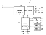
図1に示すように、電話装置10は、電話回線56が接続された回線制御部14を備えている。この回線制御部14は、電話回線56の開放制御又は閉結制御や着信検出等を行う。この回線制御部14には、着信時に電話回線56から送信される発信者電話番号に関する情報を受信するナンバーディスプレイ機能を実現するためのND部58が内蔵されている。
As shown in FIG. 1, the
また、回線制御部14には、切替回路22が接続されている。この切替回路22には、増幅回路24を介して第1スピーカ26が接続されている。この第1スピーカ26は、増幅回路24で増幅された回線制御部14の電気信号を音声に変換する。この第1スピーカ26は、ユーザの耳にあてて通話に使用される。
In addition, a
また、切替回路22には、増幅回路28を介してマイクロホン30が接続されている。このマイクロホン30は、通話に使用され、音声を電気信号に変換する。マイクロホン30により出力された電気信号は、増幅回路28で増幅されて回線制御部14に出力される。
Further, the
また、切替回路22には、増幅回路32を介して第2スピーカ34が接続されている。この第2スピーカ34は、増幅回路32で増幅された回線制御部14の電気信号を音声に変換する。この第2スピーカ34は、受話音を周囲の人にも聞かせるための拡声用のスピーカである。また、第2スピーカ34は、着信報知の鳴動も行う。なお、これらの3つの増幅回路24、28、32は、ゲインを固定しており、第1スピーカ26及び第2スピーカ34の音量やマイクロホン30の感度を変更することはできないようになっている。
Further, a second speaker 34 is connected to the
この切替回路22は、回線制御部14との接続を、第1スピーカ26用の増幅回路24とマイクロホン30用の増幅回路28側にするか、あるいは拡声用の第2スピーカ34用の増幅回路32とマイクロホン30用の増幅回路28側にするかを切り替える。
The
また、回線制御部14及び切替回路22には、制御回路(制御手段)36がそれぞれ接続されている。この制御回路36の制御により上述した切替回路22による切り替えが行われる。制御回路36は、ROM38と接続されており、ROM38に格納されているシステムプログラムに基づき各部を制御する。また、制御回路36には、所定の時間をカウントするカウンタ60が内蔵されている。
A control circuit (control means) 36 is connected to the line control unit 14 and the
制御回路36は、制御回路36の動作に必要な所定の情報が記憶されているRAM40と接続されている。また、制御回路36により回線制御部14を介して外部の通信機(例えば、電話装置)に対して電子メールを送信することができるようになっている。
The
ここで、RAM40には、所定の情報が記憶されている。具体的には、所定の電話番号(例えば、家族、友人、知人などの電話番号)と所定の暗証番号(例えば、4桁の数字など)とが対応付けられて記憶されている。なお、暗証番号として、留守番電話機などに搭載されている外線リモート操作の際に使用する暗証番号を兼用してもよい。
Here, predetermined information is stored in the
また、RAM40には、発信者に音声出力するための音声データが記憶されている。本実施形態では、例えば、「暗証番号を入力して下さい」や「暗証番号が違います」などの音声データ、発信者が入力した暗証番号がRAM40に記憶された暗証番号と一致する場合に着信音が鳴動される着信音鳴動状態を発信者に報知するための擬似リングバックトーンに関する音声データが、それぞれ記憶されている。さらに、RAM40には、発信者が入力した暗証番号がRAM40に記憶された暗証番号と一致しない内容を示すNG情報に関するデータ及び発信者から暗証番号を受信せず一定時間が経過した内容を示すNG情報に関するデータがそれぞれ記憶されている。
Further, the
尚、上記RAM40ではなく、フラッシュメモリ等の不揮発性メモリを使用しても良い。
Instead of the
また、制御回路36には、入力部44が接続されている。この入力部44は、電話番号等の入力を行うテンキー48と、通話の開始を操作する通話キー50と、通話の終了を操作する切キー52と、各種機能の設定を行う機能キー54と、後述の照明部46からディスプレイ42への照明を停止し電話装置10が鳴動不可能な状態(電源オフの状態)にする電源キー64と、を有している。
An
また、制御回路36には、所定の色のLED素子を備えた照明部46が接続されている。照明部46のLED素子の発光により、ディスプレイ42が所定の色に施される。
The
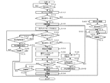
次に本実施形態に係る電話装置10の動作について説明する。図2は本実施形態に係る電話装置10の動作を示すフローチャートである。
Next, the operation of the
図2に示すように、発信者からの着信があると(ステップ10)、制御回路36により回線制御部14が制御され、着信側のユーザがハンドセットを手に取った場合でも発信者と通話状態ができないようにするオフフック無効機能が作動される(ステップ12)。このとき、ND部58により発信者電話番号に関する情報(以下、「発信者電話番号」を例に取り説明する。)が電話回線56側から受信される。オフフック無効機能が作動されると、着信時に電話回線56側から受信される発信者電話番号が予めRAM40に記憶されている所定の電話番号と一致するか否かが制御回路36により判断される(ステップ14)。着信時に電話回線56側から受信される発信者電話番号が予めRAM40に記憶されている所定の電話番号と一致すると制御回路36により判断されると、回線制御部14により電話回線56が回線閉結制御され、回線接続が実現される(ステップ16)。このとき、制御回路36により第1スピーカ26が制御され、第1スピーカ26から着信音が出力されることがない(着信音の鳴動なし)。回線接続が実現されると、発信者に対して暗証番号をDTMF信号にて送信するように促すために、予めRAM40に記憶されている音声データ(例えば、「暗証番号を入力して下さい」など)に基づいて音声合成音を電話回線56側に送出するように制御部36により制御される。これにより、発信者に対して所定の音声メッセージが出力される(ステップ18)。また、このとき、一定時間(最長で10秒間程度)の間、電話回線56からのDTMF信号の監視状態となるように制御回路36により制御される。次に、発信者から発信側の電話装置(図示省略)のダイヤル操作によって暗証番号が入力された否かが制御回路36により判断される(ステップ20)。暗証番号が入力されたと制御回路36により判断されると、発信者により入力された暗証番号が予めRAM40に記憶されている暗証番号に一致するか否かが制御回路36により判断される(ステップ22)。発信者により入力された暗証番号が予めRAM40に記憶されている暗証番号に一致すると制御回路36により判断されると、制御回路36により第1スピーカ26が制御され、第1スピーカ26から着信音が出力される(ステップ24、着信音の鳴動あり)。このとき、電話回線56側に着信音鳴動状態を報知するための疑似リングバックトーンが送出されるように制御回路36により制御される(ステップ26)。そして、制御回路36により回線制御部14が制御され、着信側のユーザがハンドセットを手に取った場合には発信者と通話状態ができるようにするオフフック有効機能が作動される(ステップ28)。次に、着信側のユーザが着信に対して応答(留守番電話機能による自動応答も含まれる)するか否かが制御回路36により判断される(ステップ30)。着信側のユーザが応答(留守番電話機能による自動応答も含まれる)したと制御回路36により判断されると、制御回路36は電話回線56側との通話回路を生成させ、これにより発信者と着信側のユーザとが通話可能な通話可能状態となる(ステップ32)。そして、発信者と着信側ユーザとの間で通話が終了すると、回線制御部14により電話回線56が開放制御され電話回線56を介しての通信状態が切断される(ステップ34)。これにより、着信側のユーザは安心して発信者と通話することができる。なお、着信側のユーザが応答(留守番電話機能による自動応答も含まれる)していないと制御回路36により判断された場合には、制御回路36により電話回線56を介しての通信状態が切断されたか否かが判断され(ステップ56)、電話回線56を介しての通信状態が切断されたと判断された場合にはそのまま終了する。また、電話回線56を介しての通信状態が切断されていないと判断された場合には、ステップ24の直前に戻る。
As shown in FIG. 2, when there is an incoming call from the caller (step 10), the line control unit 14 is controlled by the
一方、ステップ22において発信者により入力された暗証番号が予めRAM40に記憶されている暗証番号に一致しないと制御回路36により判断されると、予めRAM40に記憶されている音声データ(例えば、「暗証番号が違います」など)に基づいて音声合成音を電話回線56側に送出するように制御部36により制御される。これにより、発信者に対して所定の音声メッセージが出力される(ステップ36)。次に、発信者により複数回、暗証番号が入力され、この入力された暗証番号がRAM40に記憶されている暗証番号に一致せず、発信者からの暗証番号の入力ミスが所定の回数以上か否かが制御回路36により判断される(ステップ38)。入力ミスが所定の回数以上であると制御回路36により判断されると、ディスプレイ42には、発信者が入力した暗証番号がRAM40に記憶された暗証番号と一致しない内容を示すNG情報が発信者電話番号とともに表示される(ステップ40)。そして、回線制御部14により電話回線56が開放制御され電話回線56を介しての通信状態が切断される(ステップ34)。発信者からの暗証番号の入力ミスが所定の回数未満であると制御回路36により判断されると、ステップ18の直前に戻る。
On the other hand, when the
また、ステップ20において発信者から暗証番号の入力がされない場合には、所定の時間が経過したか否かが制御回路36のカウンタ60により判断される(ステップ42)。所定の時間が経過したか否かが制御回路36のカウンタ60により判断されると、発信者から暗証番号を受信せず一定時間が経過した内容を示すNG情報が発信者電話番号とともにディスプレイ42に表示される(ステップ44)。そして、制御回路36により電話回線56を介しての通信状態が切断されたか否かが判断され(ステップ46)、電話回線56を介しての通信状態が切断されたと判断された場合にはそのまま終了する。なお、制御回路36により通信状態が切断されていないと判断された場合には、ステップ20の直前に戻る。
If no code number is input from the caller in
さらに、ステップ14において着信時に電話回線56側から受信される発信者電話番号が予めRAM40に記憶されている所定の電話番号と一致しないと制御回路36により判断されると、制御回路36により第1スピーカ26が制御され、第1スピーカ26から着信音が出力される(ステップ48、着信音の鳴動あり)。そして、制御回路36により発信者と着信側のユーザとの間で通話が開始されたか否かが判断され(ステップ50)、発信者と着信側のユーザとの間で通話が開始されたと判断されると、制御回路36は電話回線56側との通話回路を生成させ、これにより発信者と着信側のユーザとが通話可能な通話可能状態となる(ステップ52)。なお、発信者と着信側のユーザとの間で通話が開始されていないと制御回路36により判断されると、後述のステップ54の直前に移行する。制御回路36により電話回線56を介しての通信状態が切断されたか否かが判断され(ステップ54)、電話回線56を介しての通信状態が切断されたと判断された場合にはそのまま終了する。なお、制御回路36により通信状態が切断されていないと判断された場合には、ステップ52の直前に戻る。
Further, when it is determined by the
以上のように、本実施形態の電話装置10によれば、着信時に受信した発信者電話番号がRAM40に記憶された電話番号と一致する場合には制御回路36により発信者に暗証番号を問う音声情報が出力され、発信者が入力した暗証番号がRAM40に記憶された暗証番号と一致する場合には制御回路36により回線制御部14を介して発信者と通話可能状態に制御されることにより、たとえ発信者電話番号が一致した場合でも、暗証番号も一致しない限り発信者と通話可能状態にならず、発信者の成り済まし行為によって着信側のユーザが詐欺等の被害を受けることを防止できる。
As described above, according to the
また、着信時に受信した発信者電話番号がRAM40に記憶された電話番号と一致する場合には制御回路36により着信音を鳴動することなく音声情報が出力されて、発信者が入力した暗証番号がRAM40に記憶された暗証番号と一致する場合には制御回路36により着信音を鳴動して発信者と通話可能な通話可能状態に制御されることにより、発信者電話番号を受信してから発信者が入力した暗証番号がRAM40に記憶された暗証番号と一致するまでの間は、着信音が鳴動されることがないため、着信側のユーザが誤って応答してしまうことがなく、また、着信音の鳴動に伴う騒音も防止できる。
When the caller telephone number received at the time of the incoming call matches the telephone number stored in the
また、着信時から発信者が入力した暗証番号がRAM40に記憶された暗証番号と一致するまでは、制御回路36により回線制御部14を介して発信者と通話できない非通話状態に制御されるため、着信側のユーザがハンドセットを手にとった場合でも、着信側のユーザが発信者と通話してしまうことがない。
Further, the
また、発信者が入力した暗証番号がRAM40に記憶された暗証番号と一致する場合には着信音が鳴動される着信音鳴動状態を報知するための擬似リングバックトーンが制御回路36により電話回線56側に送出されるため、発信者にイライラ感や不快感を与えてしまうことを防止できる。
Further, when the password entered by the caller matches the password stored in the
また、発信者が入力した暗証番号がRAM40に記憶された暗証番号と一致しない場合又は発信者から暗証番号を受信せず一定時間が経過した場合には、回線制御部14により電話回線56が開放制御され電話回線56を介しての通信状態が切断されるため、発信者の成り済まし行為によって着信側のユーザが詐欺等の被害を受けることを防止できる。
If the password entered by the caller does not match the password stored in the
さらに、発信者が入力した暗証番号がRAM40に記憶された暗証番号と一致しない場合又は発信者から暗証番号を受信せず一定時間が経過した場合には、発信者電話番号とともにNG情報がディスプレイ42に表示されるため、着信側のユーザは発信者電話番号とNG情報とを対応付けて知ることができ、防犯対策に役立てることができる。
Further, when the password entered by the caller does not match the password stored in the
10 電話装置
36 制御回路(制御手段)
40 RAM(記憶手段)
42 ディスプレイ(表示手段)
56 電話回線
10
40 RAM (storage means)
42 Display (display means)
56 Telephone line
Claims (2)
る情報を受信するナンバーディスプレイ機能を有する電話装置であって、
更に所定の暗証番号を記憶する記憶手段と、表示手段とを有し、
着信時に発信者に暗証番号を問う音声情報を出力し、前記発信者が入力した暗証番号が前記記憶手段に記憶された前記暗証番号と一致する場合には発信者と通話可能な状態となるように制御し、一方、前記発信者が入力した暗証番号が前記記憶手段に記憶された前記暗証番号と一致しない場合又は前記発信者から前記暗証番号を受信せず一定時間が経過した場合には、前記発信者が入力した暗証番号が前記記憶手段に記憶された前記暗証番号と一致しない旨の情報又は前記発信者から前記暗証番号を受信せず一定時間が経過した旨の情報を前記表示手段に表示するように制御する制御手段と、を有することを特徴とする電話装置。 Caller phone number that is connected to the phone line and sent from the phone line when an incoming call is received
A telephone device having a number display function for receiving information,
Furthermore, it has a storage means for storing a predetermined password and a display means,
When the incoming call is received, voice information asking the caller is output, and if the password entered by the caller matches the password stored in the storage means, a call can be made with the caller. On the other hand, when the password entered by the caller does not match the password stored in the storage means or when the password is not received from the caller, Information indicating that the personal identification number input by the caller does not match the personal identification number stored in the storage means or information indicating that a certain time has passed without receiving the personal identification number from the caller is displayed on the display means. And a control means for controlling to display.
る情報を受信するナンバーディスプレイ機能を有する電話装置であって、
表示手段と、所定の電話番号と所定の暗証番号とを対応付けて記憶する記憶手段と、着信時に受信した前記発信者電話番号が前記記憶手段に記憶された前記電話番号と一致する場合には発信者に暗証番号を問う音声情報を出力し、
前記発信者が入力した暗証番号が前記記憶手段に記憶された前記暗証番号と一致する場合には発信者と通話可能な状態となるように制御し、一方、前記発信者が入力した暗証番号が前記記憶手段に記憶された前記暗証番号と一致しない場合又は前記発信者から前記暗証番号を受信せず一定時間が経過した場合には、前記発信者が入力した暗証番号が前記記憶手段に記憶された前記暗証番号と一致しない旨の情報又は前記発信者から前記暗証番号を受信せず一定時間が経過した旨の情報を前記表示手段に表示するように制御する制御手段と、を有することを特徴とする電話装置。 Caller phone number that is connected to the phone line and sent from the phone line when an incoming call is received
A telephone device having a number display function for receiving information,
When the display means, the storage means for storing the predetermined telephone number and the predetermined personal identification number in association with each other, and the caller telephone number received at the time of the incoming call match the telephone number stored in the storage means Output voice information that asks the caller a PIN,
When the personal identification number input by the caller matches the personal identification number stored in the storage means, control is performed so that a call with the caller is possible. On the other hand, the personal identification number input by the caller is If it does not match the password stored in the storage means or if the password has not been received from the caller and a certain time has elapsed, the password entered by the caller is stored in the storage means. Control means for controlling the display means to display on the display means information indicating that the personal identification number does not match or information indicating that the personal identification number has not been received from the sender. Telephone equipment.
Priority Applications (1)
| Application Number | Priority Date | Filing Date | Title |
|---|---|---|---|
| JP2005079172A JP4530889B2 (en) | 2005-03-18 | 2005-03-18 | Telephone equipment |
Applications Claiming Priority (1)
| Application Number | Priority Date | Filing Date | Title |
|---|---|---|---|
| JP2005079172A JP4530889B2 (en) | 2005-03-18 | 2005-03-18 | Telephone equipment |
Publications (3)
| Publication Number | Publication Date |
|---|---|
| JP2006262270A JP2006262270A (en) | 2006-09-28 |
| JP2006262270A5 JP2006262270A5 (en) | 2009-01-29 |
| JP4530889B2 true JP4530889B2 (en) | 2010-08-25 |
Family
ID=37100986
Family Applications (1)
| Application Number | Title | Priority Date | Filing Date |
|---|---|---|---|
| JP2005079172A Active JP4530889B2 (en) | 2005-03-18 | 2005-03-18 | Telephone equipment |
Country Status (1)
| Country | Link |
|---|---|
| JP (1) | JP4530889B2 (en) |
Families Citing this family (4)
| Publication number | Priority date | Publication date | Assignee | Title |
|---|---|---|---|---|
| JP5262967B2 (en) * | 2009-04-30 | 2013-08-14 | 日本電気株式会社 | Mobile terminal, authentication method and program |
| JP2014204365A (en) * | 2013-04-08 | 2014-10-27 | 株式会社ナカヨ | Telephone device having function to cope with suspicious incoming call |
| JP5575974B1 (en) * | 2013-12-25 | 2014-08-20 | 株式会社ホムタ | Landline telephone |
| JP2020145569A (en) * | 2019-03-06 | 2020-09-10 | 株式会社イスコ | Incoming control device |
Citations (6)
| Publication number | Priority date | Publication date | Assignee | Title |
|---|---|---|---|---|
| JPH08289370A (en) * | 1995-04-18 | 1996-11-01 | Casio Comput Co Ltd | Base station and communication terminal in communication system |
| JPH11341149A (en) * | 1998-05-22 | 1999-12-10 | Brother Ind Ltd | Telephone set |
| JP2000092166A (en) * | 1998-09-17 | 2000-03-31 | Kenwood Corp | Telephone set |
| JP2000316050A (en) * | 1999-04-30 | 2000-11-14 | Nec Shizuoka Ltd | Portable telephone set and incoming person identification method |
| JP2001238119A (en) * | 2000-02-24 | 2001-08-31 | Olympus Optical Co Ltd | Electronic camera and remote control system therefor |
| JP2001245022A (en) * | 2000-03-01 | 2001-09-07 | Yamaha Corp | Portable telephone set |
-
2005
- 2005-03-18 JP JP2005079172A patent/JP4530889B2/en active Active
Patent Citations (6)
| Publication number | Priority date | Publication date | Assignee | Title |
|---|---|---|---|---|
| JPH08289370A (en) * | 1995-04-18 | 1996-11-01 | Casio Comput Co Ltd | Base station and communication terminal in communication system |
| JPH11341149A (en) * | 1998-05-22 | 1999-12-10 | Brother Ind Ltd | Telephone set |
| JP2000092166A (en) * | 1998-09-17 | 2000-03-31 | Kenwood Corp | Telephone set |
| JP2000316050A (en) * | 1999-04-30 | 2000-11-14 | Nec Shizuoka Ltd | Portable telephone set and incoming person identification method |
| JP2001238119A (en) * | 2000-02-24 | 2001-08-31 | Olympus Optical Co Ltd | Electronic camera and remote control system therefor |
| JP2001245022A (en) * | 2000-03-01 | 2001-09-07 | Yamaha Corp | Portable telephone set |
Also Published As
| Publication number | Publication date |
|---|---|
| JP2006262270A (en) | 2006-09-28 |
Similar Documents
| Publication | Publication Date | Title |
|---|---|---|
| US20040032503A1 (en) | Camera-equipped cellular telephone | |
| JP4530889B2 (en) | Telephone equipment | |
| KR20070018189A (en) | Apparatus for terminating calls barred in mobile phone and method there therefor | |
| JP7339804B2 (en) | CONTROLLER, COMMUNICATION DEVICE, AND CONTROL METHOD OF CONTROLLER | |
| JP4244888B2 (en) | Mobile phone terminal | |
| US8160558B2 (en) | Cellphone extensions | |
| JP2010166393A (en) | Telephone apparatus | |
| JP4863837B2 (en) | Telephone equipment | |
| KR100656472B1 (en) | Apparatus and method for transmitting sms to the caller when the absent mode is cancelled | |
| KR20030056051A (en) | Method for refusing call from specific phone number using caller ID and mobile phone implementing the same | |
| JP2010171782A (en) | Telephone apparatus | |
| JP5860080B2 (en) | Mobile terminal and mobile terminal control method | |
| JP4350023B2 (en) | Communication device | |
| KR200240708Y1 (en) | Transmission of the sound of a language for one-button dialing system | |
| KR200255558Y1 (en) | Private security apparatus of a caller id telephone | |
| JPH03244256A (en) | Malicious telephone call preventing device | |
| KR100638463B1 (en) | Wireless telecommunication terminal and method for controlling receive-alarm | |
| JP2003289371A (en) | Portable radio terminal device | |
| JP6112483B2 (en) | Communication apparatus and communication method | |
| JP5062092B2 (en) | Main device and telephone terminal that automatically responds to incoming calls during non-call function operation | |
| JP2005217969A (en) | Switchboard | |
| KR20050004422A (en) | Automatic response mode conversion method for using CID in mobile communication terminal | |
| JP2008124588A (en) | Telephone apparatus | |
| JPH08214052A (en) | Telephone set | |
| JP2010200250A (en) | Telephone apparatus |
Legal Events
| Date | Code | Title | Description |
|---|---|---|---|
| A621 | Written request for application examination |
Free format text: JAPANESE INTERMEDIATE CODE: A621 Effective date: 20080121 |
|
| A521 | Written amendment |
Free format text: JAPANESE INTERMEDIATE CODE: A523 Effective date: 20081205 |
|
| A977 | Report on retrieval |
Free format text: JAPANESE INTERMEDIATE CODE: A971007 Effective date: 20090316 |
|
| A131 | Notification of reasons for refusal |
Free format text: JAPANESE INTERMEDIATE CODE: A131 Effective date: 20090324 |
|
| A521 | Written amendment |
Free format text: JAPANESE INTERMEDIATE CODE: A523 Effective date: 20090331 |
|
| A131 | Notification of reasons for refusal |
Free format text: JAPANESE INTERMEDIATE CODE: A131 Effective date: 20090908 |
|
| A521 | Written amendment |
Free format text: JAPANESE INTERMEDIATE CODE: A523 Effective date: 20090918 |
|
| TRDD | Decision of grant or rejection written | ||
| A01 | Written decision to grant a patent or to grant a registration (utility model) |
Free format text: JAPANESE INTERMEDIATE CODE: A01 Effective date: 20100511 |
|
| A01 | Written decision to grant a patent or to grant a registration (utility model) |
Free format text: JAPANESE INTERMEDIATE CODE: A01 |
|
| A61 | First payment of annual fees (during grant procedure) |
Free format text: JAPANESE INTERMEDIATE CODE: A61 Effective date: 20100608 |
|
| R151 | Written notification of patent or utility model registration |
Ref document number: 4530889 Country of ref document: JP Free format text: JAPANESE INTERMEDIATE CODE: R151 |
|
| FPAY | Renewal fee payment (event date is renewal date of database) |
Free format text: PAYMENT UNTIL: 20130618 Year of fee payment: 3 |
|
| FPAY | Renewal fee payment (event date is renewal date of database) |
Free format text: PAYMENT UNTIL: 20130618 Year of fee payment: 3 |
|
| S111 | Request for change of ownership or part of ownership |
Free format text: JAPANESE INTERMEDIATE CODE: R313115 |
|
| FPAY | Renewal fee payment (event date is renewal date of database) |
Free format text: PAYMENT UNTIL: 20130618 Year of fee payment: 3 |
|
| R350 | Written notification of registration of transfer |
Free format text: JAPANESE INTERMEDIATE CODE: R350 |