JP4530449B2 - Cutting device - Google Patents
Cutting device Download PDFInfo
- Publication number
- JP4530449B2 JP4530449B2 JP26368599A JP26368599A JP4530449B2 JP 4530449 B2 JP4530449 B2 JP 4530449B2 JP 26368599 A JP26368599 A JP 26368599A JP 26368599 A JP26368599 A JP 26368599A JP 4530449 B2 JP4530449 B2 JP 4530449B2
- Authority
- JP
- Japan
- Prior art keywords
- cutting blade
- cutting
- liquid
- switching valve
- valve
- Prior art date
- Legal status (The legal status is an assumption and is not a legal conclusion. Google has not performed a legal analysis and makes no representation as to the accuracy of the status listed.)
- Expired - Fee Related
Links
Images


Description
【0001】
【発明の属する技術分野】
本発明は、任意の位置で断裁刃を停止させて断裁刃の移動を阻止することができる断裁装置に関するものである。
【0002】
【従来の技術】
製本工程においては、積層した用紙の一側面または三方の側面を切断して端面を切り揃える断裁装置が用いられている。図5は、このような断裁装置30の一例を示す概略の正面図である。
【0003】
図6において、テ−ブルTに所定枚数積層された用紙Pが載置されている。31はホルダ−32に取り付けられて矢視X方向に斜め方向に昇降移動する断裁刃、33は第1の連結部、34は断裁刃31を駆動する第1の油圧機構である。
【0004】
35は用紙Pを押圧するクランプ部材、36は第2の連結部、37は第2の油圧機構で、クランプ部材35を矢視Y方向に昇降移動させる。38は第1のスプリング保持部、39は第1のチェ−ン、40は第1の滑車、41は第1の接続部である。
【0005】
また、42は第2のスプリング保持部、43は第2のチェ−ン、44は第2の滑車、45は第2の接続部である。第2の油圧機構37を動作させると、クランプ部材35は第1のスプリング保持部38、第2のスプリング保持部42の弾性保持に抗して下降し、用紙Pを押圧する位置で停止する。第2の油圧機構37の動作を停止させ、動作油を排出すると、クランプ部材35は第1のスプリング保持部38、第2のスプリング保持部42の弾性により上昇して原点位置に復帰する。
【0006】
このような断裁装置においては、故障や異常が発生した場合には、安全を図る上から断裁刃の下降を防止する必要がある。このため、断裁刃の上死点付近(断裁刃がテ−ブルTの表面から最も離れた位置)に、噛み合い機構等の機械的な下降防止装置を設置して、断裁刃の下降を防止している。
【0007】
【発明が解決しようとする課題】
このように、従来の断裁刃の下降防止装置は、断裁刃の上死点付近に設けられており、断裁刃は上死点付近でのみ下降を防止できる構成としている。このため、断裁刃が上死点と下死点(断裁刃が用紙Pの断裁を終了する位置)との間の行程で停止しているときに、前記のように故障や異常が発生した場合には、断裁刃を停止させるためには油圧機構を停止させている。この状態で、駆動系や停止系に故障や異常が発生した場合には、操作者の意図に拘らず断裁刃が下降する恐れがあり、安全が図られないという問題があった。
【0008】
本発明はこのような問題に鑑み、任意の位置で断裁刃を停止させて断裁刃の移動を阻止することができる断裁装置の提供を目的とする。
【0009】
【課題を解決するための手段】
請求項1に係る発明は、被断裁物の所定個所を断裁する断裁刃と、前記断裁刃を昇降駆動する駆動源とを有する断裁装置において、前記断裁装置に、内部がピストンにより2室に区分され、区分した2室のそれぞれに液体を充満してなる液体シリンダ一を設け、前記ピストンに固定したロッドを前記断裁刃に連結するとともに、前記区分した2室の液体を通流する、その通流と通流遮断とを切替える切替弁を設けて配管し、前記切替弁の通流遮断の切替えで前記断裁刃の下降を阻止することを特徴とする。
【0010】
また、請求項2に係る発明は、請求項1に係る発明において、切替弁と並列に逆止弁を設け、前記断裁刃の上昇を自在としてなることを特徴とする。
【0011】
このように、本発明の請求項1に係る発明は、断裁刃の昇降と連動して昇降するピストンおよびロッドを設けた液体シリンダと、液体シリンダに配管を介して連通し、液体シリンダとの液体の経路を導通または遮断する弁機構を備えている。このため、上死点から下死点までの任意の位置で断裁刃を停止させ断裁刃の移動を阻止することができるので、安全性の高い操作を行なうことができる。
【0012】
また、請求項2に係る発明は、液体シリンダに配管を介して連通する弁機構として、汎用の切替弁と逆止弁とを用いているので、製造コストを低減することができる。更に、逆止弁を通る液体の経路は、断裁刃が上昇するときの一方向にのみ導通し、断裁刃が下降するときには遮断されるので、安全性が保たれる。
【0013】
【発明の実施の形態】
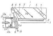
以下、本発明の断裁装置の実施の形態について図により説明する。図1は、図5で説明したクランプ部材の図示を省略した断裁装置の概略の正面図である。図1において、断裁機1には、断裁刃2、ホルダ−3、第1のガイド溝4、第2のガイド溝5、第1のガイドブロック6、第2のガイドブロック7が設けられている。第1のガイドブロック6、第2のガイドブロック7は、装置本体に固定されている。
【0014】
駆動源を動作させると、ホルダ−3に設けた第1のガイド溝4、第2のガイド溝5が第1のガイドブロック6、第2のガイドブロック7に沿って移動し、ホルダ−3は矢視X方向の斜め方向に昇降する。このため、図示していないがテ−ブル表面に積層して載置されている用紙に対し、断裁刃2も矢視X方向に斜め方向に昇降する。
【0015】
9は液体シリンダで、ロッド10、ピストン11が設けられており、動作油等の液体が満たされる。ロッド10は、連結機構8を介してホルダ−3と連結されており、ホルダ−3に設けた第1のガイド溝4、第2のガイド溝5が第1のガイドブロック6、第2のガイドブロック7に沿って昇降するに伴い、ロッド10、ピストン11も昇降する。なお、ロッド10、ピストン11は、後述のように切替弁12、逆止弁13の作用により、適宜昇降動作がロックされる。
【0016】
12は切替弁、12a、12bは、切替弁12から液体シリンダ9に連通する配管、13は、配管12a、12bの結節部12c、12dから分岐する逆止弁である。このように、図1の構成では、液体シリンダ9と配管12a、12bを通して連通している弁機構として、汎用の切替弁12と逆止弁13とを用いているので、製造コストを低減することができる。
【0017】
次に、図2〜図4の説明図により切替弁12、逆止弁13の動作を説明する。図2は、断裁刃を上死点で停止させる際の動作を示している。図2の場合には、切替弁12をオフにしている。このため、切替弁12と液体シリンダ9との液体の経路は遮断されて流路Lbには液体は流れない。
【0018】
また、逆止弁13は、液体シリンダ9のピストン11が下方から上方に移動するときにのみ、液体が流通する機構としているので、逆止弁13と液体シリンダ9との液体の経路は遮断されて流路Laにも液体は流れない。このように、切替弁12の流路Lbと逆止弁13の流路Laにはいずれも液体が流れないので、液体シリンダ9に満たされている液体は抜き出せず、ピストン11の移動が阻止され、図2の状態では断裁刃2は上死点で停止した状態を維持する。
【0019】
図3は、断裁刃を下降させる際の動作を示している。この場合には、切替弁12をオンにする。このため、切替弁12と液体シリンダ9との液体の経路が導通し、液体は配管12b、切替弁12、配管12aの経路で形成される流路Lb、Lcに流れ、液体シリンダ9に満たされている液体を抜き出してピストン11の移動を許容する。したがって、ホルダ−3は矢視Xa方向の斜め下方に移動し断裁刃2を下降させることができる。
【0020】
切替弁12をオフにすると、前記のように液体シリンダ9と連通している配管12a、12bの液体の経路は遮断されるので、断裁刃2が下降中であっても任意の位置で断裁刃2を停止させることができる。
【0021】
図4は、断裁刃を下死点から上昇させる際の動作を示している。この場合にも、切替弁12をオフにするので経路Leは遮断されて液体は流れない。しかしながら、逆止弁13を通る経路Lfは開放されているので、断裁刃2は上昇方向にのみ移動が可能となるが、下降方向への移動はできないことになる。したがって、ホルダ−3が矢視Xb方向に上昇すると、断裁刃2も上昇する。
【0022】
なお、積層された用紙のような被断裁物を押圧するクランプ部材を昇降駆動する駆動源と、被切断物を断裁する断裁刃を昇降駆動する駆動源としては、図5に示したような油圧機構を用いる構成の他に、モ−タないしサ−ボモ−タを用いる構成とすることもできる。また、本発明の断裁装置においては、被断裁物は用紙に限らず樹脂等のシ−ト状物の場合に適用できる。
【0023】
【発明の効果】
以上説明したように、本発明の請求項1に係る発明は、断裁刃の昇降と連動して昇降するピストンおよびロッドを設けた液体シリンダと、液体シリンダに配管を介して連通し、液体シリンダとの液体の経路を導通または遮断する弁機構を備えている。このため、上死点から下死点までの任意の位置で断裁刃を停止させ断裁刃の移動を阻止することができるので、安全性の高い操作を行なうことができる。
【0024】
また、請求項2に係る発明は、液体シリンダに配管を介して連通する弁機構として、汎用の切替弁と逆止弁とを用いているので、製造コストを低減することができる。更に、逆止弁を通る液体の経路は、断裁刃が上昇するときの一方向にのみ導通し、断裁刃が下降するときには遮断されるので、安全性が保たれる。
【図面の簡単な説明】
【図1】本発明の実施の形態に係る断裁装置の概略の正面図である。
【図2】図1の一方向弁と逆止弁の動作を説明する説明図である。
【図3】図1の一方向弁と逆止弁の動作を説明する説明図である。
【図4】図1の一方向弁と逆止弁の動作を説明する説明図である。
【図5】従来の断裁装置の概略の正面図である。
【符号の説明】
1 断裁装置
2 断裁刃
3 ホルダ−
4 第1のガイド溝
5 第2のガイド溝
6 第1のガイドブロック
7 第2のガイドブロック
8 連結機構
9 液体シリンダ
10 ロッド
11 ピストン
12 切替弁
13 逆止弁[0001]
BACKGROUND OF THE INVENTION
The present invention relates to a cutting apparatus that can stop a cutting blade at an arbitrary position and prevent the cutting blade from moving.
[0002]
[Prior art]
In the bookbinding process, a cutting device is used that cuts one side surface or three side surfaces of the stacked sheets to align the end surfaces. FIG. 5 is a schematic front view showing an example of such a
[0003]
In FIG. 6, a sheet P laminated on a table T by a predetermined number is placed.
[0004]
[0005]
Further, 42 is a second spring holding portion, 43 is a second chain, 44 is a second pulley, and 45 is a second connecting portion. When the second
[0006]
In such a cutting device, when a failure or abnormality occurs, it is necessary to prevent the cutting blade from descending for safety. For this reason, a mechanical lowering prevention device such as a meshing mechanism is installed near the top dead center of the cutting blade (the position where the cutting blade is farthest from the surface of the table T) to prevent the cutting blade from descending. ing.
[0007]
[Problems to be solved by the invention]
As described above, the conventional cutting blade lowering prevention device is provided near the top dead center of the cutting blade, and the cutting blade can prevent the lowering only near the top dead center. For this reason, when the failure or abnormality occurs as described above when the cutting blade is stopped at the stroke between the top dead center and the bottom dead center (the position where the cutting blade finishes cutting the paper P). In order to stop the cutting blade, the hydraulic mechanism is stopped. In this state, when a failure or abnormality occurs in the drive system or the stop system, the cutting blade may be lowered regardless of the intention of the operator, and there is a problem that safety cannot be achieved.
[0008]
In view of such a problem, an object of the present invention is to provide a cutting device capable of stopping the cutting blade at an arbitrary position and preventing the cutting blade from moving.
[0009]
[Means for Solving the Problems]
According to a first aspect of the present invention, there is provided a cutting device having a cutting blade for cutting a predetermined portion of a workpiece to be cut and a drive source for driving the cutting blade to move up and down, and the inside of the cutting device is divided into two chambers by a piston. A liquid cylinder is provided in each of the divided two chambers, and a rod fixed to the piston is connected to the cutting blade, and the liquid in the divided two chambers is allowed to flow. piping is provided a switching valve for switching between blocking flow and Tsuryu, characterized in that it prevents the downward movement of the cutting blade by switching the flowing of interruption of the switching valve.
[0010]
The invention according to
[0011]
Thus, according to the first aspect of the present invention, the liquid cylinder provided with the piston and the rod that move up and down in conjunction with the raising and lowering of the cutting blade, the liquid cylinder communicated via the pipe, and the liquid with the liquid cylinder. A valve mechanism for conducting or blocking the path is provided. For this reason, since the cutting blade can be stopped at any position from the top dead center to the bottom dead center and the cutting blade can be prevented from moving, a highly safe operation can be performed.
[0012]
In the invention according to
[0013]
DETAILED DESCRIPTION OF THE INVENTION
Embodiments of the cutting apparatus of the present invention will be described below with reference to the drawings. FIG. 1 is a schematic front view of the cutting apparatus in which the illustration of the clamp member described in FIG. 5 is omitted. In FIG. 1, the cutting machine 1 is provided with a
[0014]
When the drive source is operated, the
[0015]
A
[0016]
[0017]
Next, the operation of the
[0018]
In addition, since the
[0019]
FIG. 3 shows an operation when the cutting blade is lowered. In this case, the switching
[0020]
When the switching
[0021]
FIG. 4 shows an operation when the cutting blade is raised from the bottom dead center. Also in this case, since the switching
[0022]
Note that a hydraulic power source as shown in FIG. 5 is used as a drive source for driving up and down a clamp member that presses a workpiece to be cut such as stacked sheets and a drive source for driving up and down a cutting blade that cuts the workpiece. In addition to the configuration using the mechanism, a configuration using a motor or a servomotor can also be used. In the cutting apparatus of the present invention, the material to be cut is not limited to paper, but can be applied to a sheet-like material such as resin.
[0023]
【The invention's effect】
As described above, the invention according to claim 1 of the present invention includes a liquid cylinder provided with a piston and a rod that move up and down in conjunction with the raising and lowering of the cutting blade, the liquid cylinder communicated via a pipe, A valve mechanism for conducting or blocking the liquid path is provided. For this reason, since the cutting blade can be stopped at any position from the top dead center to the bottom dead center and the cutting blade can be prevented from moving, a highly safe operation can be performed.
[0024]
In the invention according to
[Brief description of the drawings]
FIG. 1 is a schematic front view of a cutting apparatus according to an embodiment of the present invention.
2 is an explanatory diagram for explaining the operation of the one-way valve and the check valve in FIG. 1; FIG.
3 is an explanatory diagram for explaining the operation of the one-way valve and the check valve in FIG. 1; FIG.
4 is an explanatory diagram for explaining the operation of the one-way valve and the check valve in FIG. 1; FIG.
FIG. 5 is a schematic front view of a conventional cutting apparatus.
[Explanation of symbols]
1 Cutting
4
Claims (2)
Priority Applications (1)
| Application Number | Priority Date | Filing Date | Title |
|---|---|---|---|
| JP26368599A JP4530449B2 (en) | 1999-09-17 | 1999-09-17 | Cutting device |
Applications Claiming Priority (1)
| Application Number | Priority Date | Filing Date | Title |
|---|---|---|---|
| JP26368599A JP4530449B2 (en) | 1999-09-17 | 1999-09-17 | Cutting device |
Publications (2)
| Publication Number | Publication Date |
|---|---|
| JP2001088081A JP2001088081A (en) | 2001-04-03 |
| JP4530449B2 true JP4530449B2 (en) | 2010-08-25 |
Family
ID=17392927
Family Applications (1)
| Application Number | Title | Priority Date | Filing Date |
|---|---|---|---|
| JP26368599A Expired - Fee Related JP4530449B2 (en) | 1999-09-17 | 1999-09-17 | Cutting device |
Country Status (1)
| Country | Link |
|---|---|
| JP (1) | JP4530449B2 (en) |
Families Citing this family (4)
| Publication number | Priority date | Publication date | Assignee | Title |
|---|---|---|---|---|
| JP4533313B2 (en) * | 2003-04-25 | 2010-09-01 | 大同工業株式会社 | Excitation paper cutting device |
| JP5384842B2 (en) * | 2008-02-29 | 2014-01-08 | 株式会社セーコウ | Paper sheet cutting device |
| CN109129613A (en) * | 2018-08-29 | 2019-01-04 | 安徽中鼎胶管制品有限公司 | A kind of THV pipe die cutting apparatus |
| NL2021521B1 (en) * | 2018-08-30 | 2020-04-24 | Sdd Holding B V | Cutting device and method for cutting paper |
Citations (2)
| Publication number | Priority date | Publication date | Assignee | Title |
|---|---|---|---|---|
| JPS4836786A (en) * | 1971-09-02 | 1973-05-30 | ||
| JPS54102777U (en) * | 1977-12-29 | 1979-07-19 |
-
1999
- 1999-09-17 JP JP26368599A patent/JP4530449B2/en not_active Expired - Fee Related
Patent Citations (2)
| Publication number | Priority date | Publication date | Assignee | Title |
|---|---|---|---|---|
| JPS4836786A (en) * | 1971-09-02 | 1973-05-30 | ||
| JPS54102777U (en) * | 1977-12-29 | 1979-07-19 |
Also Published As
| Publication number | Publication date |
|---|---|
| JP2001088081A (en) | 2001-04-03 |
Similar Documents
| Publication | Publication Date | Title |
|---|---|---|
| US3371569A (en) | Shear machine or the like | |
| US5860505A (en) | Device for controlling an object on a conveyor belt | |
| JP4530449B2 (en) | Cutting device | |
| KR101578841B1 (en) | Guardrail manufacture device | |
| EP3763625B1 (en) | Random case sealer | |
| CN106966174A (en) | A kind of sheet material stacking machine | |
| JP2637065B2 (en) | Processing machine with movable holding device | |
| JP2001179535A (en) | Band sawing machine | |
| CN102861864A (en) | Chain riveting method utilizing oil pressure | |
| JP2005229779A (en) | Device for stacking work | |
| JP2019116339A (en) | Braking device of track traveling-type machine | |
| JP6806449B2 (en) | Braking device for orbital machinery | |
| JP2005229781A (en) | Device for pressing stacked work | |
| US9764921B2 (en) | Folding pocket device for a buckle folding machine | |
| JP2002066837A (en) | Shearing machine | |
| JP3207527B2 (en) | Pipe clamp device for traveling cutting machine | |
| CN209766462U (en) | Stop device and scribing apparatus | |
| JP2686077B2 (en) | Work clamp device by fluid pressure | |
| CN220067842U (en) | Lamination apparatus | |
| KR102088186B1 (en) | The Single spacing unit of Multilayer metal and non-metallic panels For large automotive parts material | |
| JP2000514716A (en) | Two axis moving clamp for fixing tool to press | |
| JP2018187951A (en) | Brake of track travel type machine | |
| JP2005229780A (en) | Carrier position exchanging system | |
| JP2005224857A (en) | Apparatus for locking movable body | |
| JP3808761B2 (en) | Plastic film accumulator |
Legal Events
| Date | Code | Title | Description |
|---|---|---|---|
| A621 | Written request for application examination |
Free format text: JAPANESE INTERMEDIATE CODE: A621 Effective date: 20060901 |
|
| A977 | Report on retrieval |
Free format text: JAPANESE INTERMEDIATE CODE: A971007 Effective date: 20090423 |
|
| A131 | Notification of reasons for refusal |
Free format text: JAPANESE INTERMEDIATE CODE: A131 Effective date: 20091124 |
|
| A521 | Written amendment |
Free format text: JAPANESE INTERMEDIATE CODE: A523 Effective date: 20100113 |
|
| TRDD | Decision of grant or rejection written | ||
| A01 | Written decision to grant a patent or to grant a registration (utility model) |
Free format text: JAPANESE INTERMEDIATE CODE: A01 Effective date: 20100608 |
|
| A01 | Written decision to grant a patent or to grant a registration (utility model) |
Free format text: JAPANESE INTERMEDIATE CODE: A01 |
|
| A61 | First payment of annual fees (during grant procedure) |
Free format text: JAPANESE INTERMEDIATE CODE: A61 Effective date: 20100608 |
|
| R150 | Certificate of patent or registration of utility model |
Free format text: JAPANESE INTERMEDIATE CODE: R150 |
|
| FPAY | Renewal fee payment (event date is renewal date of database) |
Free format text: PAYMENT UNTIL: 20130618 Year of fee payment: 3 |
|
| FPAY | Renewal fee payment (event date is renewal date of database) |
Free format text: PAYMENT UNTIL: 20130618 Year of fee payment: 3 |
|
| R250 | Receipt of annual fees |
Free format text: JAPANESE INTERMEDIATE CODE: R250 |
|
| LAPS | Cancellation because of no payment of annual fees |