JP4530331B2 - Sparrow ball machine - Google Patents
Sparrow ball machine Download PDFInfo
- Publication number
- JP4530331B2 JP4530331B2 JP2003315607A JP2003315607A JP4530331B2 JP 4530331 B2 JP4530331 B2 JP 4530331B2 JP 2003315607 A JP2003315607 A JP 2003315607A JP 2003315607 A JP2003315607 A JP 2003315607A JP 4530331 B2 JP4530331 B2 JP 4530331B2
- Authority
- JP
- Japan
- Prior art keywords
- opening
- closing door
- closing
- door
- display unit
- Prior art date
- Legal status (The legal status is an assumption and is not a legal conclusion. Google has not performed a legal analysis and makes no representation as to the accuracy of the status listed.)
- Expired - Fee Related
Links
Images
Landscapes
- Pinball Game Machines (AREA)
Description
本発明は、遊技盤上に遊技球を打ち出して上がり役を成立させるように遊技し得る雀球遊技機に係り、特に裏枠に対する開閉扉の開閉時の安定性を確保し得るようにした雀球遊技機に関する。 The present invention relates to a sparrow ball game machine that can play a game ball on a game board so as to establish a rising role, and in particular, a sparrow that can ensure stability when opening and closing the door to the back frame. It relates to a ball game machine.
従来、各種遊技部品が配置された遊技盤の下部に、麻雀牌の図柄を付した所定数の入球口を備え、メダル投入口に遊技メダルが投入された後、例えば1ゲーム当たり14個の遊技球が遊技盤上に打ち出されて各遊技球がいずれかの入球口に入球した際、当該入球口に対応する麻雀牌の図柄が、上記遊技盤上に配置された画像表示部に表示されるように機能する雀球遊技機が存在する(例えば、特許文献1参照)。また近年では、メダル投入口に投入された遊技メダルを検知スイッチに基づいて検出した時点で、麻雀牌の図柄を画像表示部に適宜の組み合わせで自動的に表示(つまり自動配牌)する機能を備えた雀球遊技機も知られている。 Conventionally, a predetermined number of entrances with a mahjong tile pattern are provided at the bottom of the game board on which various game parts are arranged, and for example, 14 games per game are inserted after the game medals are inserted into the medal slot. When a game ball is launched on the game board and each game ball enters one of the entrances, an image display unit in which the pattern of the mahjong tile corresponding to the entrance is arranged on the game board There is a sparrow game machine that functions so as to be displayed on the screen (for example, see Patent Document 1). In recent years, when a game medal inserted into the medal slot is detected based on the detection switch, a function of automatically displaying a mahjong tile pattern in an appropriate combination on the image display unit (that is, automatic distribution) is provided. A sparrow ball machine equipped is also known.
上記従来の雀球遊技機は、略箱体形状の裏枠と、この裏枠に開閉可能に支持された前枠とを備え、この前枠の上部側に上記遊技盤を備えている。当該雀球遊技機では、画像表示部に表示される手牌のうちから不要な牌(以下、不要牌とも言う)が切り捨てられた際、1個の遊技球を再度打ち出し可能な状態となり、これら切り捨て操作及び再打ち出し操作が所定回数以内にて繰り返し行われ、所定の上がり役が完成した時点で得点が計算され、その得点に応じた数の遊技メダルが払い出される。 The conventional sparrow ball gaming machine includes a substantially box-shaped back frame and a front frame supported by the back frame so as to be openable and closable, and the game board is provided on the upper side of the front frame. In the sparrow ball game machine, when unnecessary spears (hereinafter also referred to as “unnecessary spears”) are discarded from the hand spears displayed on the image display unit, one game ball can be launched again. The truncation operation and the re-launch operation are repeatedly performed within a predetermined number of times, and when a predetermined rising combination is completed, a score is calculated, and a number of game medals corresponding to the score are paid out.
ところで、上述した従来の雀球遊技機では、不要牌を切り捨てる操作(捨牌操作)等を行うための操作パネルが、ガラス板を遊技盤前部に位置決めするガラス枠部の下面に略整合するようにして配置されている。このため、ガラス板の上下方向サイズに起因して、操作パネルが必要以上に雀球遊技機における下方側に位置することとなり、遊技盤に面して着座する遊技者が、眼の高さに位置する遊技盤上の画像表示部と、必要以上に下方側に配置された操作パネルとを交互に目視しつつ遊技を進めなければならず、円滑な操作性が損なわれる等の問題が生じていた。 By the way, in the above-described conventional sparrow ball game machine, the operation panel for performing an operation (discarding operation) for discarding unnecessary baskets is substantially aligned with the lower surface of the glass frame portion for positioning the glass plate at the front of the game board. Are arranged. For this reason, due to the vertical size of the glass plate, the operation panel will be located below the sparrow ball game machine more than necessary, and the player sitting facing the game board will be at eye level. The game must be advanced while alternately observing the image display unit on the game board and the operation panel disposed on the lower side more than necessary, resulting in problems such as impaired smooth operability. It was.
また、上記従来の雀球遊技機では、遊技盤の中央部に画像表示部が配置されているため、遊技盤上の遊技領域が画像表示部に圧迫されて遊技球の転動領域が規制され、障害釘の打ち込みや遊技部品の配置等のゲージ設定に苦慮するような問題が生じる。そのため、障害釘を画像表示部に近接させて配列せざるを得ない状況も生じてしまい、当該障害釘をハンマーで調整する際に、液晶ディスプレイ等からなる画像表示部を破損させる虞も生じる。 Further, in the conventional sparrow ball game machine, since the image display unit is arranged at the center of the game board, the game area on the game board is pressed by the image display part and the rolling area of the game ball is restricted. Problems such as struggling to set gauges such as driving nails and placing game parts occur. For this reason, there is a situation in which the obstacle nail must be arranged close to the image display unit, and when the obstacle nail is adjusted with a hammer, the image display unit including a liquid crystal display or the like may be damaged.
そこで、操作パネルの操作性を向上させ、画像表示部によるゲージ設定上の制限の緩和を図るために、ガラス枠部及び操作部の双方を裏枠に対して一体的に開閉できる開閉扉として構成することが、本出願人により考えられている。 Therefore, in order to improve the operability of the operation panel and ease the restrictions on the gauge setting by the image display unit, it is configured as an open / close door that can open and close both the glass frame unit and the operation unit integrally with the back frame This is considered by the applicant.
しかし、このような構成によると、障害釘の調整や引っ掛かった遊技球の除去等の処理を行う場合、従来であれば比較的軽量なガラス枠部のみを裏枠に対して回動させればよかったのに対し、ガラス枠部、操作部及び画像表示部が一体構造にされて重量が嵩んだ上記開閉扉を回動させなければならなくなる。その際、通常のガラス枠部等の支持構造と同様に、片持ち式の開閉連結支持機構を介して開閉扉を裏枠に開閉自在に支持すると、その重量に起因して開閉扉の開閉時の安定性が損われたり、適正な水平姿勢の保持が困難になるなどの虞がある。 However, according to such a configuration, when performing processing such as adjusting the obstacle nail or removing the hooked game ball, conventionally, if only the relatively lightweight glass frame portion is rotated with respect to the back frame, On the other hand, the glass door, the operation unit, and the image display unit are integrated, and the opening / closing door, which is heavy, must be rotated. At that time, when the door is opened and closed to the back frame via a cantilevered open / close connection support mechanism, like the normal glass frame support structure, the door can be opened and closed due to its weight. There is a risk that the stability of the lens may be impaired, and it becomes difficult to maintain an appropriate horizontal posture.
すなわち、裏枠に対して片持ち支持される扉類は、開閉連結支持機構を構成する軸ピン及び軸孔双方の間の径差に起因して、常にガタつきを伴って反支点側が下方に傾斜することになり、特に上述の開閉扉のように重量が嵩む場合は、開閉時や閉止状態での水平姿勢の維持が困難になる。これにより、開閉扉と裏枠との設計基準位置に配置された各構成部材が傾き変位するようなことがあると、遊技球の流路の勾配変化に起因して円滑な球流れが損なわれ、或いは、本来の設計意図に基づく遊技展開が期待できなくなるような不都合を生じる。したがって、これらの不都合を解消し得る構造を具備した雀球遊技機の出現が切望される。 That is, the doors that are cantilevered with respect to the back frame always have a backlash on the side opposite to the back due to the difference in diameter between the shaft pin and the shaft hole constituting the open / close connection support mechanism. In particular, when the weight increases as in the case of the open / close door described above, it is difficult to maintain a horizontal posture during opening and closing or in a closed state. As a result, if the constituent members arranged at the design reference positions of the open / close door and the back frame are tilted and displaced, the smooth ball flow is impaired due to the change in the gradient of the flow path of the game ball. Or, there is a disadvantage that the game development based on the original design intention cannot be expected. Therefore, the appearance of a sparrow ball game machine having a structure that can eliminate these disadvantages is eagerly desired.
本発明はこうした従来の問題点に鑑みてなされたものであり、画像表示部によるゲージ設定上の制限緩和を図りながらも、ガラス枠部及び操作部等を備えて重量の嵩む開閉扉の開閉時の安定性を確保すると共に、その開閉時や閉止状態での適正な水平姿勢を維持し得るように構成した雀球遊技機を提供することを目的とする。 The present invention has been made in view of the above-described conventional problems, and at the time of opening and closing a heavy opening / closing door provided with a glass frame portion and an operation portion while reducing the restriction on the gauge setting by the image display portion. It is an object of the present invention to provide a sparrow ball game machine configured to ensure the stability of the game machine and to maintain an appropriate horizontal posture at the time of opening and closing and in a closed state.
請求項1記載の発明は、裏枠と、遊技盤及び操作パネルを有し且つ前記裏枠に開閉可能に支持された前枠とを備え、該前枠が、前記遊技盤の前方を覆うガラス板を支持するガラス枠部を上側に且つ前記操作パネルを有する操作部を下側に夫々位置させて前記裏枠に対し一体的に開閉動作し得る第1開閉扉と、該第1開閉扉の裏面側で前記裏枠に対して開閉動作し得る第2開閉扉とを備えてなる雀球遊技機であって、
前記操作部は、遊技に必要な麻雀牌の配牌状況を含む各種情報を表示する画像表示部、該画像表示部を有する表示ユニット、及び前記操作パネルを備え、
前記第1及び第2開閉扉双方の整合面が互いに対向し得る整合部分に、前記第1開閉扉の開閉時に相対接触しつつ該第1開閉扉を前記第2開閉扉に対して担持し得る開閉補助手段を備え、
前記開閉補助手段は、前記第2開閉扉に備えた前記整合面から所定量上方に突出するように設けられた回転体と、前記第1開閉扉に備えた前記整合面に、前記回転体に弾性接触し得る形で設けられたプレート部材とを備え、
前記回転体は、その回転軸の左右両端部をホルダで支持されるとともに、前記第2開閉扉に形成された凹状のホルダ部に前記ホルダを収容固定することで該第2開閉扉に取り付けられ、
前記プレート部材は、前記第1開閉扉に設けられ該プレート部材の両側縁部を支持可能な支持溝に係合した状態で、その先端側の下面が前記第1開閉扉側の下面より上方に位置するように、かつ前記先端が該第1開閉扉の前側に突出しないように該第1開閉扉の後方に向けて取り付けられ、
前記回転体及び前記プレート部材は、前記第1開閉扉が前記第2開閉扉に閉止されたときに双方の当接状態を維持する位置に設けられ、かつ該当接状態で前記第1開閉扉の水平状態を維持するように構成された、ことを特徴とする。
The invention according to claim 1 includes a back frame and a front frame having a game board and an operation panel and supported by the back frame so as to be opened and closed, and the front frame covers the front of the game board. A first opening / closing door that can be integrally opened and closed with respect to the back frame by positioning a glass frame portion supporting the plate on the upper side and an operation portion having the operation panel on the lower side; A sparrow ball game machine comprising a second door that can be opened and closed with respect to the back frame on the back side;
The operating unit includes an image display unit for displaying various information including distribution tiles status of Mahjong tiles necessary for the game, the display unit having the image display unit, and the operation panel,
The first opening / closing door can be supported on the second opening / closing door while being relatively in contact with the alignment portion where the alignment surfaces of both the first and second opening / closing doors can face each other when the first opening / closing door is opened / closed. With opening and closing assistance means ,
The opening / closing auxiliary means includes a rotating body provided so as to protrude upward by a predetermined amount from the alignment surface provided to the second opening / closing door, and an alignment surface provided to the first opening / closing door to the rotating body. A plate member provided in a form capable of elastic contact,
The rotating body is attached to the second opening / closing door by supporting the left and right ends of the rotating shaft with holders and accommodating and fixing the holder in a concave holder portion formed on the second opening / closing door. ,
The plate member is provided in the first opening / closing door and is engaged with a support groove capable of supporting both side edges of the plate member, and the lower surface on the tip side is higher than the lower surface on the first opening / closing door side. Is attached to the rear of the first door so that the tip does not protrude to the front of the first door,
The rotating body and the plate member are provided at positions where both the contact states are maintained when the first opening / closing door is closed by the second opening / closing door, and the first opening / closing door is in the corresponding contact state. It is configured to maintain a horizontal state .
請求項1記載の発明によれば、従来の雀球遊技機では遊技盤上に位置していた画像表示部が操作パネルに一体的に配置されるので、画像表示部に表示された配牌等を目視しながら捨牌を選択し、選択した捨牌を操作パネルにて即座に切り捨てる等の操作が容易になることにより、画像表示部の視認性と共に操作パネルの操作性が大幅に向上し、また画像表示部が遊技盤上に存在しないことにより、遊技領域の配置の自由度と共にゲージ設定の自由度が増大する。そして、第1開閉扉と第2開閉扉との整合部分に開閉補助手段を備えるので、ガラス枠部、操作部及び画像表示部を一体的に備えて重量が嵩む第1開閉扉を、開閉補助手段によって、裏枠に閉止された第2開閉扉側に担持しつつ開閉動作させることができる。従って、開閉時の安定性を確保し得ると共に、開閉時や閉止状態での第1開閉扉の裏枠に対する適正な水平姿勢を維持することが可能になる。また、開閉補助手段が、回転体とプレート部材という極めて簡素な部材を組み合わせた形で、上述の重量が嵩む第1開閉扉を、裏枠側に閉止された第2開閉扉に対して充分な強度で支え得る機能を実現しているので、雀球遊技機に開閉補助手段を実装する際のコストを最小限に抑えることが可能になる。 According to the first aspect of the present invention, in the conventional sparrow ball game machine, the image display unit located on the game board is integrally arranged on the operation panel. This makes it easy to perform operations such as selecting the trash while visually observing the image, and immediately truncating the selected trash on the operation panel, thereby greatly improving the operability of the operation panel as well as the visibility of the image display section. Since the display unit does not exist on the game board, the degree of freedom of gauge setting increases with the degree of freedom of arrangement of game areas. Since the opening / closing assisting means is provided at the matching portion between the first opening / closing door and the second opening / closing door, the glass door, the operation unit, and the image display unit are integrally provided, and the first opening / closing door that is heavy is opened / closed assisting. The means can be opened and closed while being held on the second opening / closing door side closed by the back frame. Therefore, stability at the time of opening and closing can be ensured, and an appropriate horizontal posture with respect to the back frame of the first opening and closing door at the time of opening and closing and in a closed state can be maintained. In addition, the opening / closing auxiliary means is a combination of a very simple member such as a rotating body and a plate member, and the above-mentioned first opening / closing door, which is heavy, is sufficient for the second opening / closing door closed on the back frame side. Since the function that can be supported by the strength is realized, it is possible to minimize the cost when the opening / closing auxiliary means is mounted on the sparrow ball game machine.
以下、本発明の雀球遊技機の実施形態として、遊戯場等に設置される雀球遊技機10について図1ないし図8を参照して説明する。
Hereinafter, as an embodiment of a sparrow ball game machine of the present invention, a sparrow
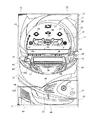
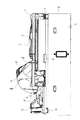
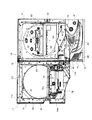
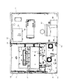
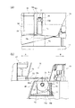
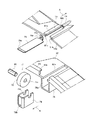
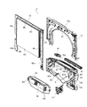
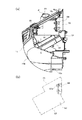
なお、図1は本実施形態における雀球遊技機10の外部構造を示す正面図、図2は本雀球遊技機10の前枠におけるガラス枠部と操作部の一体開閉部分をやや開放した状態で示す側面図、図3は本雀球遊技機10の前枠における上記一体開閉部分を開放した状態で示す正面図、図4は本雀球遊技機10の前枠全体を開放して裏枠の内部構造を示す正面図である。また、図5は本雀球遊技機10における開閉補助機構(開閉補助手段)の要部を拡大して示す図であり、同図(a)はプレート部材がローラに接触し始める直前の状態を示す平面図、同図(b)はこの直前状態を実線で示す側面断面図である。更に、図6は開閉補助機構の要部を拡大して示す分解斜視図、図7は本雀球遊技機10の前枠における上記一体開閉部分を分解した状態で示す斜視図、図8は本雀球遊技機10におけるガラス枠部下方に位置する操作部を示す図であり、同図(a)は操作パネルを一部破断した状態で示す側面図、同図(b)は操作パネルの配置構成を模式的に示す側面図である。
1 is a front view showing the external structure of the sparrow
図1ないし図3に示すように、本雀球遊技機10は、略箱体形状の裏枠11と、この裏枠11の前部一側に開閉連結支持機構12を介して開閉可能に支持された前枠13とを備えている。
As shown in FIGS. 1 to 3, the sparrow
前枠13は、ガラス枠部15と操作部16とが上下一体的に結合された形で裏枠11に対し開閉連結支持機構12、12Aを介して開閉し得るように支持された第1開閉扉17と、この第1開閉扉17の裏面側において裏枠11に対し開閉連結支持機構12を介して開閉し得るように支持された第2開閉扉19とを備えている。
The
第1開閉扉17は、図3に示すように、裏枠11に対し先に閉止された第2開閉扉19に対して閉塞された状態で、第2開閉扉19の前部における上記開閉連結支持機構12、12Aと反対側に位置する施錠機構20を介して施錠されるように構成されている。
As shown in FIG. 3, the first opening /
第1開閉扉17のガラス枠部15は、図1及び図3に示すように、略半円状に開口する開口部21と、この開口部21の外周に亘って設けられた演出用ランプ部23と、後述するガラス支持機構とを備えている。また第1開閉扉17の操作部16は、図1ないし図3に示すように、遊技盤22の下部側において前方に膨出するように形成されており、裏枠11側から(図2の右側)から前枠13の前方(図2の左側)に向かって所定角度で下方に傾斜する上部面16aと、この上部面16aの前方縁部から下方に向かって丸みを帯びて膨出する下部面16bとを備えている。
As shown in FIGS. 1 and 3, the
操作部16の上部面16aには操作パネル33が設けられている。この操作パネル33には、遊技に必要な麻雀牌の配牌状況を含む各種情報を表示する液晶ディスプレイ等からなる画像表示部35が、上部面16aの傾斜、つまり操作パネル33の傾斜に沿う形で一体的に配置されている。更に上部面16aには、画像表示部35の下側縁部の長手方向に亘って配列された複数(本実施形態では、配牌の13牌とツモ牌に対応する1牌とに相当する14個)の捨牌ボタン36と、画像表示部35の左右に位置するベット(BET)ボタン37及びリーチボタン39とが設けられている。なお、上記捨牌ボタン36は、各々対応するボタンを適時押圧操作することで捨牌操作を行うことができる。
An
更に、上部面16aにおける操作パネル33の左方にメダル投入口40及びメダル返却ボタン41が配設され、操作パネル33の右方に、所定の操作を行うための各種操作ボタン42が配設されている。また、操作部16の下部面16b上部における左右両端部には、演出用ランプ43が夫々配設されている。
Further, a
画像表示部35には、図示はしないが、捨牌、チャンス役、聴牌時の上がり牌、メダル残数、ドラ牌・裏ドラ牌、ツモ牌、或いはゲームの流れに対応するキャラクタ等が表示される。また、画像表示部35の表示は、例えば、メダル投入口40から遊技メダルが1枚投入された際、それまで表示されていたデモンストレーション画面が通常遊技画面に切り替わり、これにより、雀球遊技機10は遊技球打ち出し可能な状態となる。なお、第1開閉扉17における操作部16の裏側には、画像表示部35を有する表示ユニット54が収納配置されている(図3参照)。
Although not shown in the drawing, the
一方、第2開閉扉19は、上部側に、ガラス枠部15の開口部21から露出するように設けられた遊技盤22を備え、中間部に、打ち出し部53と、打ち出された遊技球を案内する湾曲面状の遊技球ガイド52とを備えている。更に第2開閉扉19は、下部側に、メダル受皿45と、このメダル受皿45の上方及び左方に夫々設けられた放音部46と、メダル受皿45の右方に設けられた発射レバー32及び天狗47と、メダル受皿45の左下方に設けられた灰皿49とを備えている。更にメダル受皿45の略中央部には、メダル排出口50が設けられている。なお、第2開閉扉19の裏面側下部の2箇所には、図4に示すように、上記2箇所の放音部46に夫々対応するようにスピーカ46aが配置されている。
On the other hand, the second opening / closing
そして、遊技盤22上には、略中央部に特別入球口(以下、アタッカーと言う)25が配設され、このアタッカー25の上方中央部に通過口(以下、ゲートと言う)26が配設され、このゲート26の上方にはランプ27が配設されている。更に、ゲート26の左右には入球口29が夫々配設され、またアタッカー25の下方には、所定の図柄が夫々表示された複数の下部入球口30が配置され、更にアタッカー25の左右には風車31が夫々配設されている。なお、図示はしないが、これらアタッカー25等の各種遊技部品の周囲には、所要のゲージ設定に応じた多数本の障害釘が打ち込まれている。
On the
上記下部入球口30は、詳細な図示は省略するが、例えば一万から九万、及び一筒から九筒までの各麻雀牌が表示された入球口、並びに東、南、西、北、白、発、中が夫々表示された入球口などを備えており、各入球口の上部には、所要のゲージ設定に応じて不図示の障害釘が打ち込まれている。従って、発射レバー32の操作によって遊技盤22上に打ち出された遊技球(図示せず)は、遊技盤22上の障害釘等に当たって落下方向を変化させつつ、上記入球口のいずれかに入賞することになる。なお、牌の種類は、上記に限定されることなく、他の組み合わせとすることも可能であり、また入球口を増やし或いは減少させて構成することも可能である。
Although the detailed illustration of the
次に、本雀球遊技機10の裏枠11の内部構造について図4を参照して説明する。同図に示すように、第1開閉扉17及び第2開閉扉19からなる前枠13全体を開放した状態において、裏枠11の内部には、電源基板55、主制御基板56、メダルホッパ57、メダル払出し装置48、及びメダルタンク60が上部から下部に向かって順次設けられている。なお、図中の符号51は、図3に示した打ち出し部53と一体的に構成される発射装置を示している。
Next, the internal structure of the
引き続き、図3及び図7を併せて参照し、第1開閉扉17の構成について詳細に説明する。即ち、両図に示すように、第1開閉扉17の上側に位置するガラス枠部15は、開口部21を有し且つ該開口部21を囲繞する略コの字状に形成された枠体15aを備えている。枠体15aの裏面側には、透明のガラス板62を中央部に嵌め込み得るように略コの字状に結合されたフレーム部材63、64、65が、複数のネジ孔66を夫々貫通して枠体15a側に螺合する複数の固定用ネジ(図示せず)を介して堅固に組み付けられている。
Next, the configuration of the first opening / closing
上記フレーム部材64、65は、枠部材15側から操作部16側の略下端縁まで延設された延設部64a、65aを夫々有しており、これら延設部64a、65aが、枠体15aにネジ止めされたフレーム部材64、65から操作部16側に延び、且つ操作部16の枠体16cの後部にネジ止めされることにより、ガラス枠部15と操作部16とが堅固に一体的に結合される。これにより、遊技盤22の前方を覆うべきガラス板62を第1開閉扉17に対し一体的に支持すると共に、当該ガラス板62の下側縁部62a(図3)を、ガラス枠部15側から操作部16側に所定寸法(例えば、90mm)突出させてオーバラップした形で支持するガラス支持機構が実現されている。
The
そして、図7及び図8に示すように、第1開閉扉17の下側に位置する操作部16は、上記枠体16cに、画像表示部35を有する表示ユニット53を収納し得る収納空間Sを備えている。この収納空間Sは、前方(図7の右上方、図8の左方)に向かって略半球面状に膨出すると共に、画像表示部35の画面サイズに対応させて上部面16aに形成された表示部露出口16dに連通している。
As shown in FIGS. 7 and 8, the
操作部16の収納空間S内には、表示部露出口16dの左右端近傍から垂下するように一対のブラケット67が設けられている。これら一対のブラケット67夫々に設けられた支持孔67aに対し、表示ユニット54の左右端部に備えた各支持部材68を嵌め込むことにより、表示ユニット54が、画像表示部35の画面を上部面16aの表示部露出口16dから露出させて収納空間S内に収容される形で、所定位置に位置決め固定される。なお、画像表示部35を透視可能な透明パネル(図示せず)が表示部露出口16dの全面に亘って設けられており、これにより、画像表示部35の画面の保護が図られている。
In the storage space S of the
また、上部面16aにおける表示部露出口16dの両端部分には、各種操作ボタン42やメダル返却ボタン41が配置され、且つ表示部露出口16cの下方側には捨牌ボタン36が配置される。なお、図7及び図8における符号61は、メダル識別器(セレクタ)を示している。
そして、上述のように裏枠11に対して操作部16と一体的に開閉し得るように該操作部16に結合されたガラス枠部15は、図8(a)に示すように、収納空間Sにおいてガラス板62を、その下部を操作部16の表示ユニット54背面側に所定量(例えば、90mm)オーバラップさせる形で支持している。
As described above, the
次に、本実施形態における雀球遊技機10に設けられた開閉補助機構(開閉補助手段)について、図5及び図6を参照して詳細に説明する。なお、図5(b)及び図6において、矢印Aで示す方向が雀球遊技機10の前部側であり、矢印Bで示す方向が後部側である。
Next, the opening / closing assistance mechanism (opening / closing assistance means) provided in the sparrow
すなわち、開閉補助機構70は、図5(a),(b)に示すように、ローラ保持部71を介して第2開閉扉19側に支持されたローラ(回転体)72(図2及び図3も併せて参照)と、プレート保持部73を介して第1開閉扉17側に支持されたガイドプレート75(図2、図3及び図7も併せて参照)とを備えている。
That is, as shown in FIGS. 5A and 5B, the opening /
上記ローラ72は、例えば硬質の合成樹脂材料で形成されており、図6に示すように、中心部に軸孔72aが貫通穿設されている。またガイドプレート75は、例えば金属材料で形成されており、図6に示すように、一端部に固定用ブラケット部75aを、他端部に案内面75cを夫々備えている。固定用ブラケット部75aには、不図示の固定用ネジが挿通される挿通孔75bが形成されている。また、上記案内面75cは、図5(b)に示すように、ガイドプレート75が後述の整合面82(図6参照)に対して略々平行に配置された状態で、第1開閉扉17側からローラ72側に向かって所定角度で上方に傾斜するように形成されている。
The
上記ローラ保持部71は、発射レバー32近傍の放音部46の内方側に設けられたホルダ部76と、このホルダ部76の底面76a上に突出形成された固定用凸部76b(図5(b))と、ホルダ79とを備えている。ホルダ79は、保持すべきローラ72の両側を挟み込むような平面視略コの字形状を呈しており、背面下部にネジ挿通孔79bが貫通穿設されている。そしてホルダ79は、ネジ挿通孔79bに挿通されて固定用凸部76bの雌ネジ孔に螺合した固定用ネジ77を介して、固定用凸部76b、つまりホルダ部76に固定されている。また、ホルダ79の両側面における上縁部には、半円状の軸受け凹部79aが形成されており、この軸受け凹部79aには、ローラ72の軸孔72aに回転自在に嵌合した支軸80が係合している。
The
また図6に示すように、第2開閉扉19の下部側の、上記ガイドプレート75に対応する箇所に設けられた整合面82には、雀球遊技機10の前後方向(矢印A、B方向)に沿うようにローラ突出用溝82aが切り欠き形成されており、整合面82の下部には、ローラ突出用溝82aに対応するように上述のホルダ部76が設けられている。また、整合面82における遊技機後部側の縁部には、第2開閉扉19の本体側に接合されるべき壁部83が形成されており、この壁部83は、上記ローラ突出用溝82aに対応する位置に切り欠き部83aが形成されている。従って、上記ローラ72は、ホルダ79に支軸80を介して回転自在に支持され、且つ上部側をローラ突出用溝82aから所定寸法dだけ突出させた形(図5(b)参照)で、ホルダ部76の前後方向の略々中間部分に保持される。なお、上記ローラ72における上記所定寸法dは、第1開閉扉17がその開閉時及び第2開閉扉19への閉止位置において水平状態を維持し得る突出量に設定されれば良い。
Further, as shown in FIG. 6, the
更に図6に示すように、操作部16の枠体16c(図7参照)における整合面16eには、第2開閉扉19側の上記ローラ72に対応する位置に、プレート保持部73が設けられている。このプレート保持部73は、雀球遊技機10の前後方向(矢印A、B方向)に沿うように切り欠かれて固定用ブラケット部75aの挿入を許容するための溝81cと、ガイドプレート75の両側縁部を係合させた形で該プレート75を堅固に保持し得る係合溝(支持溝)81bと、この係合溝81bに係合・保持されたガイドプレート75の下面を雀球遊技機前後方向に沿って露出させ、該プレート75に転接するローラ72を受け入れるための開口部81aとを備えている。
Further, as shown in FIG. 6, a
更に、整合面16e上における溝81cの端部に設けられたリブ部84には、雌ネジ孔84aが形成されている。この雌ネジ孔84aには、係合溝81bに係合された状態のガイドプレート75の挿通孔75bに挿通された固定用ネジ(図示せず)が螺合される。これによりガイドプレート75は、図5(b)に示すように、例えば第1開閉扉17が第2開閉扉19に向かって閉止される際、整合面82のローラ突出用溝82aから上方に所定寸法d突出するローラ72に対し、該ローラ72の上端面より下方側にプレート下面を位置させると共に、案内面75cをローラ上端面に乗り上げ可能な状態となるようにして、プレート保持部73にて堅固に保持される。
Furthermore, a
以上の構成を備えた本雀球遊技機10では、ゲーム1回について遊技メダル1枚をメダル投入口40に投入する毎に、画像表示部35の表示面に14牌の自動配牌が行われると共に、打ち直し用の例えば14個の遊技球が使用可能に設定される。或いはこれに代えて、ゲーム1回について遊技メダル1枚を投入する毎に、例えば24個(配牌用の遊技球14個、打ち直し用の遊技球10個)の遊技球を使用可能となるように設定することもできる。
In the present sparrow
そして、遊技メダルを1枚投入してゲーム開始可能な状態にした後、発射レバー32の操作により、遊技球を1個ずつ遊技球ガイド52を介して遊技盤22上の任意の位置に打ち出すことができる。また、遊技球の打ち直し時には、画像表示部35上に表示された14牌のうちから遊技者が適宜選択した捨牌を、捨て牌ボタン36の操作に基づいて切り捨てる。これにより、捨牌に相当する牌が画像表示部35から消滅すると共に、当該捨牌に対応して1個の遊技球が打ち出し可能な状態となる。これらの操作を所定回数以内で実行し、14枚の牌により麻雀の上がり役が完成した時点でゲームを終了させて所定の操作を行うと、獲得した得点に応じて遊技メダルがメダル排出口50から払い出され、これにより、遊技者に利益が還元されることとなる。
Then, after putting one game medal into a state in which the game can be started, by operating the
そして、上述した遊技時等において、例えば、遊技盤22上の障害釘に遊技球が引っ掛かったり、操作部16のメダル投入口40から投入したメダルが詰まったりした場合、本雀球遊技機10にあってはガラス枠部15と操作部16とが裏枠11に対して上下一体的に開閉し得るように結合されているので、ガラス枠部15及び操作部16の双方を一度に開放することで、遊技球や遊技メダルの除去など、種々の事態に円滑に対処することができる。
When the game ball is caught on the obstacle nail on the
更に、本雀球遊技機10では、ガラス板62をその下部を操作部16に所定量オーバラップした形でガラス枠部15に支持したことにより、遊技盤22下方における非遊技領域を省いた形で、操作パネル33を遊技盤22側に可能な限り寄せるように構成することができる。これにより、遊技盤22に面して着座する遊技者が、眼の高さに位置する遊技盤22の遊技領域と、適度の高さに位置する操作パネル33とを交互に目視しながら、遊技を操作性良く円滑に進めることができる。
Furthermore, in the present sparrow
しかも、従来は遊技盤上に位置していた画像表示部35が操作パネル33に一体的に配置されるので、画像表示部35が遊技盤22上に存在しないことにより、遊技領域の配置の自由度と共にゲージ設定の自由度が増している。また、障害釘を画像表示部35に近接配置することがなくなるので、障害釘の調整時に画像表示部35を破損するような事態を確実に回避できる。更に、遊技者側に所定角度で傾斜する画像表示部35に表示された配牌等を目視しながら捨牌を選択し、選択した捨牌を操作パネル33にて即座に切り捨てる等の操作が容易になるので、画像表示部35の視認性と共に、操作パネル33の操作性が大幅に向上する。
In addition, since the
また、ガラス板62がその下部を操作部16に所定量オーバラップさせた形でガラス枠部15にて支持されたことにより、専用サイズのガラス板が不要となり、パチンコ台で一般的に用いられるガラス板(405mm×405mm)を兼用化できるので、遊技店側での取り扱い上の利便性が向上する。
Further, since the
更に、本雀球遊技機10にあっては、画像表示部35を一体に有する表示ユニット54が、画面を操作パネル33から露出させる形で操作部16の収容空間Sに収容されるので、画像表示部35の設置と同時に該表示部35の画面以外の部分を覆うことができ、従って、画像表示部35を容易且つ確実に保護しつつ、雀球遊技機11の組み立てを速やかに行うことができる。また、上記表示ユニット54は、左右端部に備えた各支持部材68を操作部16側の支持孔67aに係脱することにより、操作部16に対する着脱性(交換性)が向上されている。
Further, in the present sparrow
そして、第1開閉扉17を必要に応じて開放する際には、まず、図1の状態において施錠機構20を操作して開錠し、第1開閉扉17を、その適宜の箇所(例えば、開閉連結支持機構12、12Aと反対側の側部)を把持して図1の手前側に引きつつ、開閉連結支持機構12、12Aを中心として第2開閉扉19に対して回動させる。この際、第1開閉扉17と第2開閉扉19との各整合面16e、82が対向する整合部分に設けられた開閉補助機構70は、次のように機能する。
And when opening the
例えば、第1開閉扉17の開放時には、図5(b)示すように、二点鎖線のようにローラ72に完全に乗り上げてΔx分だけ上方に撓み変形していたガイドプレート75が、その下面をローラ72に接触させながら第1開閉扉17の矢印A方向への移動に伴い同方向へ移動する。これにより、第1開閉扉17は、ガラス枠部15と、画像表示部35を有する操作部16とを一体的に有することによる重量を、ガイドプレート75を介してローラ72に担持されながら、スムーズに開放される。
For example, when the first opening / closing
一方、開放状態の第1開閉扉17を第2開閉扉19側に閉止する際には、図5(b)の実線で示すように、下面がローラ72上端面より下降した状態のガイドプレート75が、同図矢印B方向への移動に伴い、案内面75cをローラ72に徐々に接触させて該ローラ72の回転を促しつつ、全体を二点鎖線のように撓ませながらローラ72に乗り上げていく。そして、第1開閉扉17が第2開閉扉19に対して完全に閉止されたとき、ガイドプレート75は、Δx分だけ上方に撓み変形した状態でローラ72に完全に乗り上げる。これにより、第1開閉扉17は、その重量を、ガイドプレート75を介してローラ72にて担持された状態で閉塞された後、施錠機構20の操作によって施錠される。
On the other hand, when closing the opened first opening / closing
したがって、本雀球遊技機10によると、片持ち式の開閉連結支持機構12、12Aを介して第1開閉扉17が開閉自在に支持されたものでありながら、第1開閉扉17と第2開閉扉19との整合部分に開閉補助機構70を備えたことにより、ガラス枠部15、操作部16及び画像表示部35を一体的に備えて重量が嵩む第1開閉扉17を、開閉補助機構70を介して、裏枠11に閉止された第2開閉扉19側に担持しながら開閉動作させることができる。従って、第1開閉扉17の開閉時の安定性を確保し得ると共に、開閉時や閉止状態での第1開閉扉17の裏枠11に対する適正な水平姿勢の維持を実現し得る。そして、上記開閉補助機構70は、ローラ72とガイドプレート75という極めて簡素な部材を組み合わせた形で、上述の重量が嵩む第1開閉扉17を、裏枠11側に閉止された第2開閉扉19に対して充分な強度で支え得る機能を実現しているので、雀球遊技機10に開閉補助機構70を実装する際のコストを最小限に抑えることが可能になる。
Therefore, according to the present sparrow
なお、本実施の形態では、開閉補助機構70をガイドプレート75とローラ72とを用いて構成したが、開閉補助機構70はこのような構成に限らず、例えば、ローラ72に代えて、回転せずにガイドプレート75を摺動させて支えるような部材を、該プレート75と合わせて構成することもできる。また、ローラ72とガイドプレート75の位置関係を逆にして構成することも可能である。
In the present embodiment, the opening /
また、本実施の形態では、ガラス枠部15と操作部16とをフレーム部材63〜65を介して一体的に結合したが、このような構成に限らず、例えばフレーム部材63〜65を用いることなく、ガラス枠部15及び操作部16に夫々相当する部分を最初から一体成形した構成に本発明を適用しても良いことは言うまでもない。また例えば、画像表示部35の画面にタッチパネルを設け、このタッチパネルに捨て牌ボタン36等の操作手段を配置することにより、操作パネル33上の省スペース化や操作性の向上を図ることも可能である。
Moreover, in this Embodiment, although the
本発明に係る雀球遊技機は、ガラス枠部を上側に且つ操作部を下側に位置させて裏枠に対し一体的に開閉し得るような開閉扉を備える雀球遊技機に用いて有用であり、特に上記開閉扉の開閉時の安定性を確保する必要性のある雀球遊技機に適している。 The sparrow ball game machine according to the present invention is useful for a sparrow ball game machine having an opening / closing door that can be opened / closed integrally with the back frame with the glass frame portion on the upper side and the operation portion on the lower side. In particular, it is suitable for a sparrow ball game machine that needs to ensure stability when the door is opened and closed.
10…雀球遊技機
11…裏枠
12、12A…開閉連結支持機構
13…前枠
15…ガラス枠部
15a…枠体
16…操作部
16e…整合面
17…第1開閉扉
19…第2開閉扉
22…遊技盤
33…操作パネル
35…画像表示部
54…表示ユニット
70…開閉補助機構(開閉補助手段)
71…ローラ保持部
72…ローラ(回転体)
73…プレート保持部
75…ガイドプレート(プレート部材)
75c…案内面
82…整合面
DESCRIPTION OF
71 ...
73 ...
75c ...
Claims (1)
前記操作部は、遊技に必要な麻雀牌の配牌状況を含む各種情報を表示する画像表示部、該画像表示部を有する表示ユニット、及び前記操作パネルを備え、
前記第1及び第2開閉扉双方の整合面が互いに対向し得る整合部分に、前記第1開閉扉の開閉時に相対接触しつつ該第1開閉扉を前記第2開閉扉に対して担持し得る開閉補助手段を備え、
前記開閉補助手段は、前記第2開閉扉に備えた前記整合面から所定量上方に突出するように設けられた回転体と、前記第1開閉扉に備えた前記整合面に、前記回転体に弾性接触し得る形で設けられたプレート部材とを備え、
前記回転体は、その回転軸の左右両端部をホルダで支持されるとともに、前記第2開閉扉に形成された凹状のホルダ部に前記ホルダを収容固定することで該第2開閉扉に取り付けられ、
前記プレート部材は、前記第1開閉扉に設けられ該プレート部材の両側縁部を支持可能な支持溝に係合した状態で、その先端側の下面が前記第1開閉扉側の下面より上方に位置するように、かつ前記先端が該第1開閉扉の前側に突出しないように該第1開閉扉の後方に向けて取り付けられ、
前記回転体及び前記プレート部材は、前記第1開閉扉が前記第2開閉扉に閉止されたときに双方の当接状態を維持する位置に設けられ、かつ該当接状態で前記第1開閉扉の水平状態を維持するように構成された、ことを特徴とする雀球遊技機。 A back frame and a front frame having a game board and an operation panel and supported by the back frame so as to be openable and closable, and the front frame includes a glass frame portion supporting a glass plate covering the front of the game board A first opening / closing door that can be opened / closed integrally with the back frame by positioning an operation unit having the operation panel on the upper side and on the lower side, and the back frame on the back side of the first opening / closing door. A sparrow ball game machine comprising a second opening / closing door capable of opening and closing,
The operating unit includes an image display unit for displaying various information including distribution tiles status of Mahjong tiles necessary for the game, the display unit having the image display unit, and the operation panel,
The first opening / closing door can be supported on the second opening / closing door while being relatively in contact with the alignment portion where the alignment surfaces of both the first and second opening / closing doors can face each other when the first opening / closing door is opened / closed. With opening and closing assistance means ,
The opening / closing auxiliary means includes: a rotating body provided so as to protrude upward by a predetermined amount from the alignment surface provided in the second opening / closing door; and the alignment surface provided in the first opening / closing door to the rotating body. A plate member provided in a form capable of elastic contact,
The rotating body is attached to the second opening / closing door by supporting the left and right ends of the rotating shaft with holders and accommodating and fixing the holder in a concave holder portion formed on the second opening / closing door. ,
The plate member is provided in the first opening / closing door and is engaged with a support groove capable of supporting both side edges of the plate member, and the lower surface on the tip side is higher than the lower surface on the first opening / closing door side. Is attached toward the rear of the first door so that the tip does not protrude to the front side of the first door,
The rotating body and the plate member are provided at positions where both the contact states are maintained when the first opening / closing door is closed by the second opening / closing door, and the first opening / closing door is in the corresponding contact state. A sparrow ball game machine characterized by being configured to maintain a horizontal state.
Priority Applications (1)
| Application Number | Priority Date | Filing Date | Title |
|---|---|---|---|
| JP2003315607A JP4530331B2 (en) | 2003-09-08 | 2003-09-08 | Sparrow ball machine |
Applications Claiming Priority (1)
| Application Number | Priority Date | Filing Date | Title |
|---|---|---|---|
| JP2003315607A JP4530331B2 (en) | 2003-09-08 | 2003-09-08 | Sparrow ball machine |
Publications (2)
| Publication Number | Publication Date |
|---|---|
| JP2005080847A JP2005080847A (en) | 2005-03-31 |
| JP4530331B2 true JP4530331B2 (en) | 2010-08-25 |
Family
ID=34415816
Family Applications (1)
| Application Number | Title | Priority Date | Filing Date |
|---|---|---|---|
| JP2003315607A Expired - Fee Related JP4530331B2 (en) | 2003-09-08 | 2003-09-08 | Sparrow ball machine |
Country Status (1)
| Country | Link |
|---|---|
| JP (1) | JP4530331B2 (en) |
Family Cites Families (5)
| Publication number | Priority date | Publication date | Assignee | Title |
|---|---|---|---|---|
| JPH0632148Y2 (en) * | 1989-09-14 | 1994-08-24 | 株式会社森木工 | Pachinko machine front frame support |
| JP2000189558A (en) * | 1998-12-28 | 2000-07-11 | Samii Kk | Pachinko machine with mah-jongg game |
| JP3801431B2 (en) * | 2000-09-14 | 2006-07-26 | 株式会社藤商事 | Bullet ball machine |
| JP3773409B2 (en) * | 2000-11-07 | 2006-05-10 | サミー株式会社 | Frame support structure for vertical gaming machines |
| JP2002159637A (en) * | 2000-11-28 | 2002-06-04 | Fuji Shoji:Kk | Combination game machine |
-
2003
- 2003-09-08 JP JP2003315607A patent/JP4530331B2/en not_active Expired - Fee Related
Also Published As
| Publication number | Publication date |
|---|---|
| JP2005080847A (en) | 2005-03-31 |
Similar Documents
| Publication | Publication Date | Title |
|---|---|---|
| JP4338041B2 (en) | Game machine | |
| JP5257474B2 (en) | Game machine | |
| JP2006334072A5 (en) | ||
| JP5257473B2 (en) | Game machine | |
| JP4530329B2 (en) | Sparrow ball machine | |
| JP4530331B2 (en) | Sparrow ball machine | |
| JP2009066353A (en) | Bullet ball machine | |
| JP4530330B2 (en) | Sparrow ball machine | |
| JP4709871B2 (en) | Bullet ball machine | |
| JP5088936B2 (en) | Coin insertion unit | |
| JP4605757B2 (en) | Bullet ball machine | |
| JP2008237405A (en) | Pachinko machine | |
| JP5033973B2 (en) | Game machine | |
| JP5257475B2 (en) | Game machine | |
| JP4614428B2 (en) | Prize-winning device for bullet ball machines | |
| JP4614432B2 (en) | Prize-winning device for bullet ball machines | |
| JP2008018144A (en) | Game board of game machine | |
| JP4618776B2 (en) | Prize-winning device for bullet ball machines | |
| JP2005185382A (en) | Pachinko game machine | |
| JP5044732B2 (en) | Game machine | |
| JP4614431B2 (en) | Prize-winning device for bullet ball machines | |
| JP5800785B2 (en) | Bullet ball machine | |
| JP5259760B2 (en) | Bullet ball machine | |
| JP4905703B2 (en) | Game machine | |
| JP2007054394A (en) | Pinball game machine |
Legal Events
| Date | Code | Title | Description |
|---|---|---|---|
| A621 | Written request for application examination |
Free format text: JAPANESE INTERMEDIATE CODE: A621 Effective date: 20060905 |
|
| RD02 | Notification of acceptance of power of attorney |
Free format text: JAPANESE INTERMEDIATE CODE: A7422 Effective date: 20070627 |
|
| A977 | Report on retrieval |
Free format text: JAPANESE INTERMEDIATE CODE: A971007 Effective date: 20090914 |
|
| A131 | Notification of reasons for refusal |
Free format text: JAPANESE INTERMEDIATE CODE: A131 Effective date: 20091006 |
|
| A521 | Request for written amendment filed |
Free format text: JAPANESE INTERMEDIATE CODE: A523 Effective date: 20091120 |
|
| TRDD | Decision of grant or rejection written | ||
| A01 | Written decision to grant a patent or to grant a registration (utility model) |
Free format text: JAPANESE INTERMEDIATE CODE: A01 Effective date: 20100601 |
|
| A01 | Written decision to grant a patent or to grant a registration (utility model) |
Free format text: JAPANESE INTERMEDIATE CODE: A01 |
|
| A61 | First payment of annual fees (during grant procedure) |
Free format text: JAPANESE INTERMEDIATE CODE: A61 Effective date: 20100604 |
|
| R150 | Certificate of patent or registration of utility model |
Free format text: JAPANESE INTERMEDIATE CODE: R150 |
|
| FPAY | Renewal fee payment (event date is renewal date of database) |
Free format text: PAYMENT UNTIL: 20130618 Year of fee payment: 3 |
|
| FPAY | Renewal fee payment (event date is renewal date of database) |
Free format text: PAYMENT UNTIL: 20130618 Year of fee payment: 3 |
|
| FPAY | Renewal fee payment (event date is renewal date of database) |
Free format text: PAYMENT UNTIL: 20130618 Year of fee payment: 3 |
|
| FPAY | Renewal fee payment (event date is renewal date of database) |
Free format text: PAYMENT UNTIL: 20130618 Year of fee payment: 3 |
|
| R250 | Receipt of annual fees |
Free format text: JAPANESE INTERMEDIATE CODE: R250 |
|
| R250 | Receipt of annual fees |
Free format text: JAPANESE INTERMEDIATE CODE: R250 |
|
| R250 | Receipt of annual fees |
Free format text: JAPANESE INTERMEDIATE CODE: R250 |
|
| R250 | Receipt of annual fees |
Free format text: JAPANESE INTERMEDIATE CODE: R250 |
|
| R250 | Receipt of annual fees |
Free format text: JAPANESE INTERMEDIATE CODE: R250 |
|
| LAPS | Cancellation because of no payment of annual fees |